 Hanxin Chen1,2Mengying Luan3Mei Xue1,2Mingquan Wang1,2Hailang Tian1,2Yinghao Qu1,2
 Qiang Yuan3*
 Mingtian Zhang3*
- 1Chongqing Institute of Surveying and Mapping Science and Technology, Chongqing, China
- 2Technology innovation Center for Spatio-Temporal Information and Equipment of Intelligent City, Ministry of Natural Resources, Chongqing, China
- 3State Key Laboratory of Coal Mine Disaster Dynamics and Control, National Innovation Center for Industry-Education Integration of Energy Storage Technology, School of Resources and Safety Engineering, Chongqing University, Chongqing, China
Analyzing overburden movement, surface deformation and fracturing in mines with extremely thick, hard cover is critical for coal mine safety. In this context, the present study examines the 021N2 fully-mechanized top-coal caving face beneath an open-pit slope with extremely thick, hard overburden, developing structural-mechanics models and performing PFC-2D numerical simulations to investigate the structural evolution of the overlying rock mass. The simulations reveal that vertical displacement dominates the slope’s post-mining deformation, and that a force-chain arch forms above the goaf with associated stress fracturing and redistribution. In addition, mining-induced surface fissures create significant air leakage into the goaf, posing a high risk of spontaneous combustion. These findings provide a theoretical basis and technical guidance for controlling thick-overburden caving faces under open-pit slopes, thereby informing safer mining operations and engineering practice in similar contexts.
1 Introduction
Energy is a fundamental pillar of modern industrial civilization, serving as both the driving force behind national economic operations and a crucial element of national security strategies (Ahmad and Zhang, 2020; Li et al., 2022; Le et al., 2024; Liu et al., 2021). Data from the BP Statistical Review of World Energy 2023 reveals that global energy consumption has risen by more than 45% over the past 2 decades, with emerging economies accounting for 78% of this increase (Zou et al., 2021). As the largest global energy producer and consumer, China recorded a total energy consumption of 5.41 billion tons of standard coal in 2023. Within the framework of the “Dual Carbon” strategy, developing a clean, low-carbon, safe, and efficient energy system has emerged as a critical national priority (Wang G. et al., 2019). Despite the significant growth in renewable energy capacity, coal continues to dominate China’s energy mix, constituting 55.3% of primary energy consumption in 2023—a reduction from 68.5% in 2000—while still maintaining an annual consumption of over 2.8 billion tons (Cheng et al., 2018; Song and Kuenzer, 2014; National Bureau of Statistics of China, 2024). This structural reliance originates from China’s resource endowment, which is described as “abundant coal, limited oil, and scarce natural gas.” Proven coal reserves amount to 207 billion tons, constituting 94% of the nation’s fossil energy reserves (Zhang et al., 2022). Notably, major coal-producing regions, including Shanxi, Shaanxi, Inner Mongolia, Ningxia, and Gansu, possess extensive thick coal seams. These seams, characterized by burial depths of under 500 m and single-layer thicknesses exceeding 20 m, are of strategic importance for national energy security due to their efficient exploitation potential (Wu et al., 2018). However, the mining process encounters significant technical challenges, particularly under extremely thick and hard overburden conditions. In typical mining areas such as Jungar and Shendong, the thickness of the overlying bedrock often surpasses 30 times the mining height. For instance, beneath the Heidaigou open-pit slope, there are 300-m-thick sandstone layers, which render conventional roof control theories inadequate for these complex geological conditions (Cuong et al., 2022; Zhang et al., 2023; Ma et al., 2023). Strata movement in such contexts shows a “multi-key-layer composite fracture” pattern. The mining-induced stress fields are 2–3 times more complex than those in conventional scenarios. Microstructurally, fracture zones in overlying strata can reach heights of 25–35 times the mining height, forming water-conducting fissures that penetrate to the surface. Macroscopically, mining influence radii exceeding 800 m may cause slope displacements that surpass early warning thresholds by 30%, posing severe geohazard risks (Liu et al., 2022; Qian and Xu, 2019).
Establishing mechanical models is a prevalent approach for analyzing the movement patterns of roof strata in coal mining. Cao et al. combined the Anderson model with the Mohr-Coulomb failure criterion to develop a mechanical model for fault rupture (Cao et al., 2024). Sun et al. formulated a mechanical model to describe the continuous bending movement of rock layers under variable load conditions in pillarless mining (Sun et al., 2020). Zhao et al., utilizing the long beam theory, established a preliminary fracture mechanical model for the thick and hard roof stratum and analyzed the fracture step distance of the roof (Zhao et al., 2017). In order to better understand and predict the stability and safety of overlying strata during coal mining processes, Sun et al. investigated the movement and delamination progression of overburden during the extraction of extremely thick coal seams beneath thick conglomerate layers, employing analogue physical model experiments and a photoelectric multi-parameter distributed sensing system (Sun et al., 2024). Wang et al. presented an equivalent numerical simulation method to explore the collapse mechanisms within the overlying sandy strata caused by karst cavities (Wang et al., 2022). Wang et al. employed ANSYS for numerical simulations to assess the development patterns of separation spaces under diverse horizontal overburden configurations, analyzing the failure properties of overburden rocks and the evolution of separation spaces filled with various overburden materials, as well as investigating the stress distribution and evolutionary patterns throughout the separation development process (Wang Z. et al., 2019). Digital Elevation Model (DEM) techniques are widely used for the quantitative analysis of topographical features (Cao et al., 2021; Xiong et al., 2021). Qu et al., leveraging the preprocessing of DEM data and simulations utilized FLO-2D software to assess the impacts of debris flow control measures under varying rainfall conditions in Zhangxian Fangjia Gully (Qu et al., 2024). An et al. generated DEMs via the Kriging interpolation technique and applied multi-stage DEM differential processing to extract ground subsidence data, thereby attaining high-precision ground subsidence information (An et al., 2024).
Current research often synergizes theoretical analysis with numerical simulation to study the evolutionary patterns of overburden strata. The complexity of geological conditions in coal mining introduces a multitude of factors influencing the progression of overburden and the distribution of ground fissures, with impacts that vary across different aspects. Notably, the geological characteristics of fully mechanized caving faces are characterized by a thick and hard overburden structure, domain where current research remains insufficient. Considering the specific geological conditions of the 021N2 working face, this study constructs a mechanical model and employs PFC-2D software for numerical simulation to conduct an in-depth study on the structure of the overlying rock in a thick-seam longwall mining face. The goal is to elucidate the deformation characteristics and force chain network of the coal mine slope under mining conditions, as well as the deformation and failure characteristics of the overlying rock affected by mining activities. This study aims to establish a robust theoretical foundation and provide technical support for the stability control of thick-seam longwall working faces under open-pit slopes, and to act as a reference for the safe operation of coal mines under analogous engineering conditions.
Through a “theoretical modeling–numerical validation–mechanism extrapolation” framework, this study systematically clarifies overburden structural evolution laws and disaster mitigation pathways for steeply inclined coal seams under ultra-thick hard overburden.
2 Geological conditions
2.1 Mine area overview
The coal mine studied employs inclined shaft development, with the primary inclined shaft utilizing belt transportation and the secondary inclined shaft employing a single-hook skip hoisting method. Figure 1 shows the geographical location of the mine. The ventilation system is of the centrally divided type, with mechanical extraction as the ventilation method. The main and auxiliary inclined shafts function as intake air passages, while the return air shaft is designated for exhaust air. The underground mining area retains a geological resource reserve of 38.21 Mt, with a designed production capacity of 1.2 Mt/a. The entire development area is stratified into a single level, positioned at an elevation of +350 m. This level functions as a unified mining district, featuring a combined layout that sequentially extracts the No. 2 and No. 1 coal seams from the surface downward. The No. 2 coal seam has an average thickness of 6.12 m, while the No. 1 coal seam averages 29.27 m in thickness, separated by an interval of 12.05 m. The mining district is bifurcated into a northern and southern wing, with three sections allocated to the northern wing and two to the southern wing. Each section employs fully mechanized top-coal caving technology, utilizing a retreat mining approach and the caving method for roof management. Owing to constraints related to coal seam occurrence and mining technical conditions, numerous adverse factors affect fire prevention and control during the mining period in the fully-mechanized caving face of the second section in the northern wing of the coal mine: the coal seam is highly prone to spontaneous combustion, and predicting and providing early warnings for such combustion under gas conditions is particularly challenging. There is a significant amount of residual coal in the goaf of the thick-seam fully-mechanized caving face, and the geological conditions surrounding the coal seam occurrence are intricate, with well-developed leakage fractures present beneath the thick, hard overburden in the open-pit slope. Consequently, an in-depth study of the structure of the fully-mechanized caving face beneath the thick overburden roof is undertaken using theoretical analysis and numerical simulation methodologies.
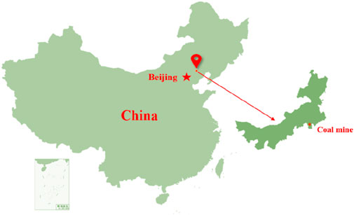
Figure 1. Geographic location map of the mine.
2.2 Overview of the working face
The main technical parameters of the 021N2 working face are shown in Table 1.
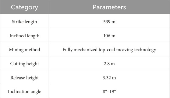
Table 1. Technical parameters of working face.
The ventilation method employed is a U-shaped full negative pressure system, with roof management exclusively executed via the caving method. The coal seam being extracted in 021N2 working face is the No. 2 coal seam, demonstrating substantial variations in strike and an inclination angle that varies from 8° to 19°. The pronounced stratification and jointing are clearly shown in Figure 2, illustrating the conditions at the coal seam’s roof and floor. The primary water source in the working face originates from the sandstone layers at the roof and floor, characterized by the absence of water accumulation in the goaf and minimal water conduction along faults. Throughout the mining process, localized roof dripping can occur, reaching a maximum inflow rate of 1 m3/h.
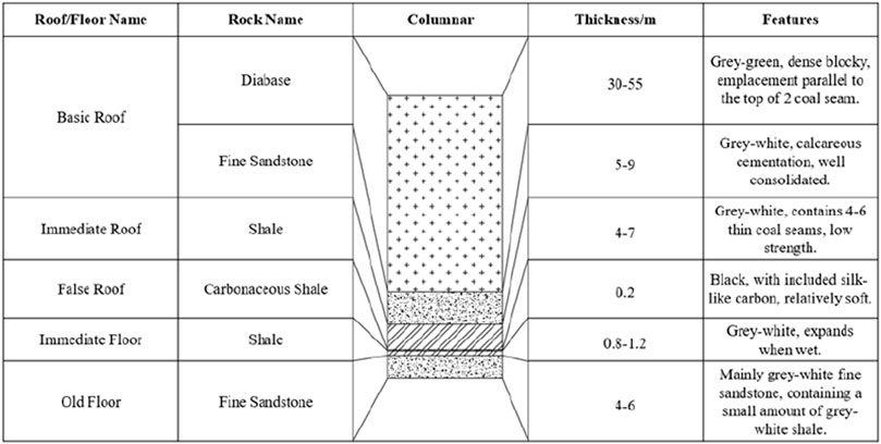
Figure 2. The conditions of the coal seam roof and floor.
3 Establishment and structural analysis of the overlying rock mechanic’s model
3.1 Establishment of the roof strata mechanic’s model
Within the overburden strata overlying the 021N2 fully mechanized caving face, the thickness of the diabase layer varies between 30 and 55 m. Owing to the rigid nature of diabase, the collapse of the overburden strata during the face retreat exhibits irregularity. Consequently, the stress conditions of the roof during face retreat are analyzed, with the face considered as an inclined mining plane and horizontal stress influence excluded in this analysis. Throughout the mining process, significant deformation and destruction are anticipated in the upper part of the goaf, along the strike direction of the coal seam (Kien and Lanh, 2021; Kang et al., 2023). At this time, if the axial force is neglected, the roof of the goaf can be approximated as a beam with one end embedded and the other end simply supported for calculation, as shown in Figure 3.

Figure 3. One end fixed and the other end simply supported roof structure model.
The variable definitions involved in the formula are shown in Table 2.
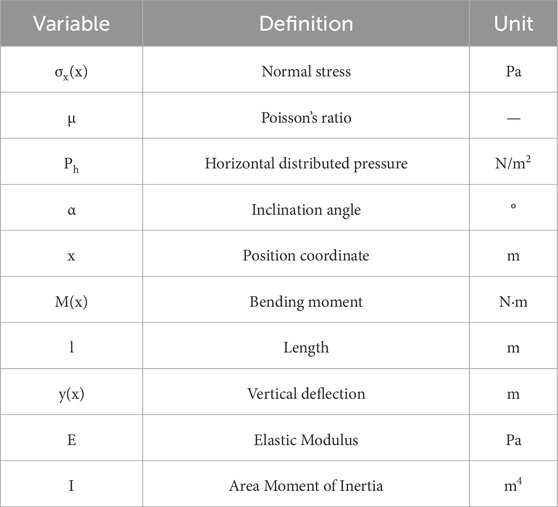
Table 2. The definition of variables.
Within the realm of elasticity mechanics, the stress distribution, bending moments, and deflection equations of this model are established as Equations 1–3:
In this context, Ph = γH, where H represents the average mining depth in meters. By setting the first derivative of the deflection
At this point, the maximum deflection is Equation 4:
Following the extraction of an inclined coal seam beneath an open-pit slope, the overlying rock strata undergo collapse. Under the influence of gravity, the collapsed roof descends to the lower part of the goaf, aligning with the coal seam’s strike, thereby forming a supporting structure. Consequently, the lower section of the goaf roof experiences significantly less influence from mining activities than the upper section. The axial movement and rotation of the lower beam are constrained, whereas the upper beam is assumed to have unrestricted rotation and axial movement. The mechanical model is established, depicting the beam with the lower part fixed and the upper part simply supported, as illustrated in Figure 4. The rock beam is subjected to an axial concentrated load P and a normally distributed load q1. Here, P denotes the axial pressure applied to the beam by the overlying rock strata; q1 denotes the force exerted by the overlying rock strata on the beam in the y-direction, comprising the weight component of the rock strata in the y-direction and the resistance from the backfill of the collapsed gob in the mining area. The axial component of the beam’s self-weight stress is considerably smaller than P. Thus, in this study, we disregard the axial component of the beam’s self-weight stress.
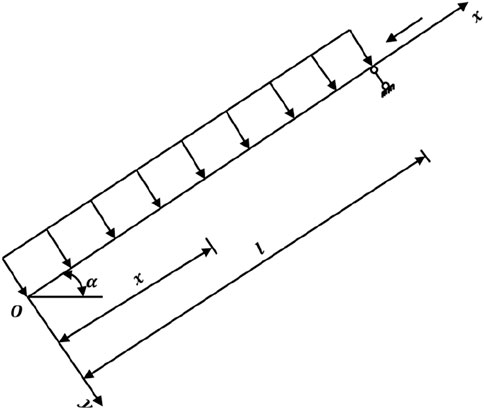
Figure 4. Stress analysis of the roof strata in the direction of coal seam dip.
Following the extraction of the coal seam, the overlying strata will collapse, filling the goaf with caved rocks that consequently apply a backfilling force to the goaf roof. If the backfilling force exerted by the caved rocks on the goaf roof is neglected, assuming the upper and lower boundary mining depths of the coal seam are H1 and H2, respectively, and the overburden rock layer has a unit weight of γ, then as the Equation 5 shows:
When accounting for the reactive force of the backfilled gob rocks within the goaf, it is postulated that the maximum backfilling force exerted by the caved rocks on the roof strata in a steeply inclined goaf can be expressed as:
Then q1 will be Equation 6:
3.2 Roof strata bending deformation analysis
To ascertain the distribution pattern of internal forces across various beam cross-sections, the most straightforward and practical approach involves establishing the correlation between the external forces applied to the beam and the internal forces within the beam structure. This methodology obviates the necessity for intricate analyses of the micro-segment equilibrium within beam-column structures. The analysis is confined to the 0xy plane, where the external forces are applied to the beam. It is postulated that the load’s moment about the centroid is minimal, and the beam’s torsional stiffness is substantial, leading to negligible torsional deformation. A differential segment of length dx at coordinate x is considered, with the force distribution depicted in Figure 5.
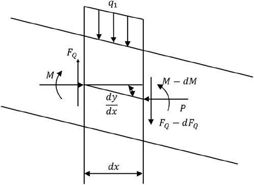
Figure 5. Force analysis of a micro-element.
Let P denote the axial force, M the bending moment at the left cross-section, and FQ the shear force in the y-direction. Given that the angle between the horizontal line and the beam’s axis is considered negligible, we can apply the equilibrium equations: ΣFy = 0, ΣM = 0, to derive Equations 7, 8:
By disregarding the higher-order terms of second-order and above, we derive the following:
Utilizing the equilibrium equation in the y-direction, ΣFy = 0, we derive:
By substituting Equation 10 into Equation 9, we derive:
By disregarding the deformations attributed to shear forces and the axial stretching and contraction of the beam, the resulting approximate differential equation in the axial direction of the beam structure is obtained as follows:
Utilizing Equations 11 and 12, the fundamental differential equation governing the axis of a beam structure under the influence of both axial and transverse forces is derived as Equation 13:
Considering the beam structure is fixed at one end and simply supported at the other, the resulting boundary conditions are Equation 14:
By employing the Rayleigh-Ritz method (Akgoz and Civalek, 2022), we derive the approximate form of the axial equation as Equation 15:
Therefore, the Equations 16, 17:
The bending strain energy of the beam structure, U, is given by the integral
T1 = PΔ, where Δ represents the axial elongation due to the action of force P. Assuming that under the action of force p, the differential element dx transforms to dl, then Equation 19:
By integrating over the length l, we derive Equations 20, 21:
Therefore:
The work done by the roof pressure q1, denoted as T2, involves an infinitesimal load increment q1 dx, which can be treated as a concentrated load. Thus, the work done by q1dx is calculated by integrating q1a1x2 (1−x) with respect to x, yielding the work done by q1 as Equation 22:
In accordance with the principle of conservation of energy, the work performed by external forces equates to the alteration in internal deformation energy; therefore Equations 23–25:
By substituting Equation 25 into Equation 15, we obtain:
Let q1 = γH1cosα and P = γH1sinα. Substituting these into Equation 26 and neglecting the cubic terms, we derive Equation 27:
Taking the derivative with respect to y, we find
3.3 Roof strata span analysis
The maximum tensile stress within the rock stratum is represented by σtm, while the tensile strength is denoted by [σt]. Failure of the rock stratum occurs when σtm exceeds [σt] (Xie et al., 2013; Zhang et al., 2024). The radius of curvature at which the rock stratum experiences bending deformation is Equation 29:
The rock beam structure is prone to bending and fracture under conditions characterized by minimal deflection, where the deflection is significantly less than the span of the structure. Consequently, the deformation of the rock stratum is classified as a scenario of small deformation, with the angle of rotation
Considering that
Consequently, the radius of curvature of the rock stratum can be approximated as:
Given that x = l, the rock stratum exhibits maximum deflection. By substituting the second derivative y'' into Equation 32, we can determine the minimum curvature of the rock beam structure as Equation 33:
At the point where the roof strata experience maximum deflection, the corresponding maximum tensile deformation is given by Equation 34:
According to Hooke’s Law, the maximum tensile stress within the rock beam structure can be expressed as Equation 35:
From the critical failure condition where σtm equals [σt], we derive the following Equation 37:
From Equation 36, we can derive the following:
Therefore, the resulting equation is Equation 38:
4 Numerical modeling and result analysis of 021N2 fully mechanized caving face mining
4.1 Coal mine slope model construction
The Discrete Element Method is a numerical technique employed for investigating the kinematic behavior of granular systems, predicated on Newton’s second law of motion (Zuo et al., 2024; Adajar et al., 2020). By iteratively updating the velocities and positions of individual particles, the method deterministically evolves the entire granular system. In contrast to continuous medium models, the discrete element method can directly describe the macroscopic mechanical properties of granular systems at the particle scale.
Based on the engineering geological data collected from the site, the distribution of rock strata is depicted in Figure 6, with the coal seam overlain by shales, diabase, mudstones, and other rock types. The geological parameters for each stratum are detailed in Table 3.
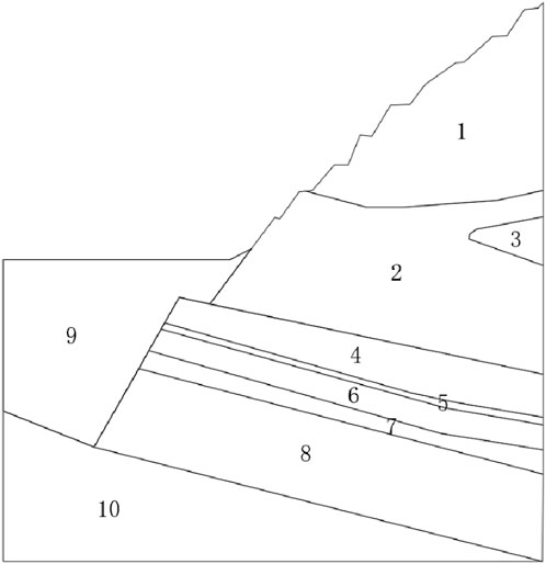
Figure 6. Distribution of stratum in the mining profile (1. shale, 2. diabase, 3. sand laminae, 4. mudstone, 5. carbonaceous shale, 6. 2coal, 7. shaly sand, 8. 1coal, 9. backfill soil, 10. sandstone.).
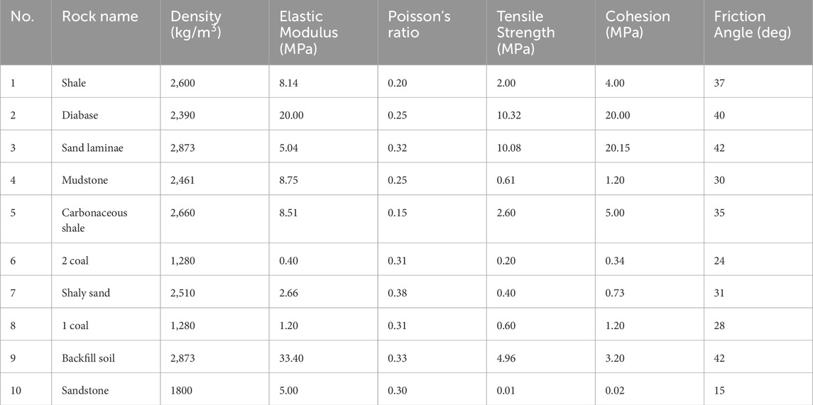
Table 3. Geological parameters of the mining profile.
A granular flow program is utilized to construct a two-dimensional slope model. Initially, particles within the model boundary are generated with a radius ranging from 0.8 m to 1.6 m. The initial porosity is established at 0.16, with a density of 1800 kg/m3 and a damping coefficient of 0.7. Subsequently, both inter-particle and particle-wall interactions are modeled using a linear contact model (Yuan et al., 2019), characterized by an elastic modulus of 720 MPa, a normal-to-shear stiffness ratio of 4, and a friction coefficient of 0.5.
The CAD layer illustrated in Figure 6 is imported into the granular flow program, and particles are subsequently grouped in accordance with the distribution of rock strata. Considering the characteristics of each stratum and the focus of this study, particularly mudstones and coal seams, the particle distribution within each stratum is refined by substituting large-radius particles with two smaller-radius ones. Post-refinement, the particle radius range is specified as 0.40 m–0.85 m. Particles located outside the boundary are excluded (if present), yielding a total of 29,554 particles.
Based on the stratum grouping detailed in Table 3, the mechanical parameters for particles in each layer are reassigned, and the inter-particle contact is modeled using the parallel bond contact model, denoted as linear bond. The model incorporates a bonding component acting in parallel with a linear element, thereby establishing elastic interactions between contacts. The parallel bond facilitates the transmission of forces and moments between distinct particles and correlates with the maximum normal and shear stresses at the particle’s periphery. Should either of these maximum stresses surpass the corresponding bond strength, the parallel bond will rupture, Consequently, the parallel bond contact model reverts to a linear contact model. Through iterative trials and adjustments, the final mechanical parameters for the model have been determined and are presented in Tables 4, 5. The resulting granular flow model of the coal mine slope is illustrated in Figure 7. To facilitate a more intuitive analysis of the deformation and failure processes of the coal-rock mass during mining, a key observation area has been cropped, with the area enclosed in red in the figure delineating the mining scope, hereinafter denoted as the slope local area.
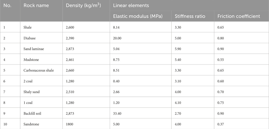
Table 4. Model parameters of the mining profile (linear elements).
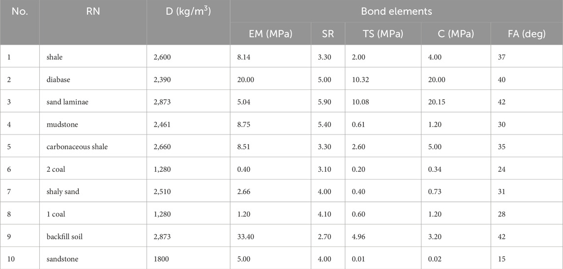
Table 5. Model parameters of the mining profile (bond elements), (which Rock Name: RN, Density: D, Elastic Modulus: EM, Stiffness Ratio: SR, Tensile Strength: TS, Cohesion: C, Friction Angle: FA).
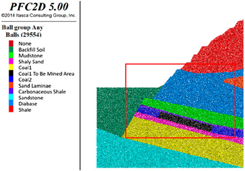
Figure 7. Schematic diagram of the slope sliding area.
Considering the specific site conditions and actual working conditions, a computational analysis of the coal mine slope model under the mining conditions specific to Seam 2 was performed. In the undisturbed natural state, the equilibrium horizontal and vertical displacement fields are depicted in Figures 8a,b, respectively. The maximum horizontal displacement is capped at 0.5 m, occurring predominantly at locations with steeper slope angles, while the maximum vertical displacement is similarly limited to 0.5 m. The corresponding damage field at this stage is presented in Figure 8c, where the inter-particle contact adheres to the initially specified parallel bond contact model, linear bond. The force chain field of the coal mine slope in its natural state is illustrated in Figure 8d, evidencing the extension and development of force chains from the slope face into the deep underground, culminating in an intricate network of force chains. The intensity of the force chains in the vicinity of the rock and soil free surface is comparatively low, with a gradual increase in intensity as depth progresses, with contact forces in the order of 105 N.
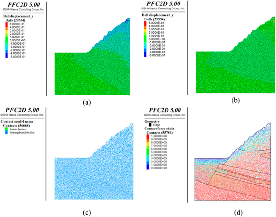
Figure 8. Computational Results of the Coal Mine Slope Model in the Natural State (a) Horizontal displacement field under natural conditions, (b) Vertical displacement field, (c) Damage field, (d) Slope force chain field).
4.2 Numerical simulation results analysis
The target coal seam to be mined has a height of approximately 9 m. The working face employs a single longwall mining method with a fully mechanized caving process, retreat mining, and all coal ribs are managed using the full caving method.
(1) After 600 steps of excavation
In the initial stages of excavation, the rock mass displacement is predominantly vertical due to the roof collapse, as depicted in Figure 9a, reaching a maximum vertical displacement of 0.02 m. The horizontal displacement is generally negligible, as illustrated in Figure 9b, with the maximum occurring at the working face edges; however, the horizontal displacement of the top and bottom plates is an order of magnitude of 10^3 m. The displacement vector field presented in Figure 9c further indicates that the primary movement is the subsidence of the upper rock mass attributable to the collapse of the coal seam roof. As observed in Figure 9d, post-mining roof collapse results in the emergence of a force chain arch structure above the goaf, where robust force chains constitute the arch’s backbone, and the surrounding weaker force chains provide support. These two types of force chains collectively establish a re-distributed force chain network within the goaf.
(2) After 2000 steps of excavation post-excavation
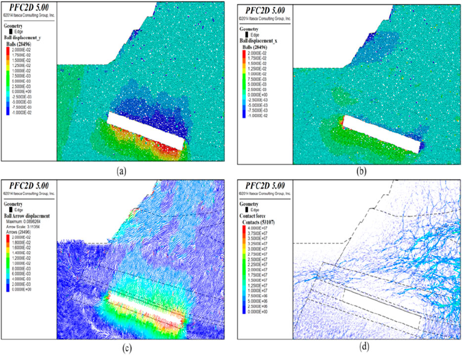
Figure 9. Simulation results after 600 steps of excavation (a) vertical displacement field after mining disturbance, (b) horizontal displacement field, (c) displacement vector field, (d) local force chain field).
After 2000 steps of excavation, the displacement of the rock mass continues to be predominantly vertical, as depicted in Figure 10a, reaching a maximum vertical displacement of 0.06 m. The horizontal displacement is illustrated in Figure 10b, with a maximum horizontal displacement of 0.04 m, located at the two sides of the working face, and the horizontal displacement of the floor plate is 0.03 m. The displacement vector field, as displayed in Figure 10c, shows that the coal seam roof persists in collapsing, leading to further settlement of the overlying rock strata. As observed in Figure 10d, following the roof collapse post-mining, the extent of the force chain arch above the goaf has broadened, and the intensity of the force chains in the void area beneath is considerably low, with the force chain network undergoing redistribution.
(3) Calculation after excavation for 4,000 steps
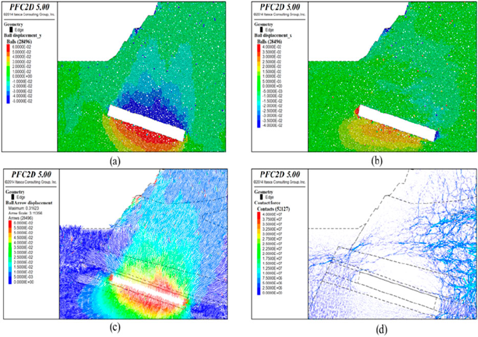
Figure 10. Simulation results after 2000 excavation steps (a) vertical displacement field after mining disturbance, (b) horizontal displacement field, (c) displacement vector field, (d) local force chain field).
Post-excavation, the calculation was carried out for 4,000 steps. The vertical displacement of the rock-soil mass is depicted in Figure 11a, with a maximum vertical displacement of 0.2 m observed at the roof. The horizontal displacement is illustrated in Figure 11b, with the maximum horizontal displacement of 0.04 m persisting on both sides of the working face, and significant horizontal displacements are also emerging in the central portion of the floor and the upper right corner of the roof. The displacement vector field is presented in Figure 11c, with the maximum displacement magnitude recorded at 0.18 m. The roof of the coal seam induces subsidence in the overlying rock layers, with the area of influence progressively expanding to the surface slope. Within the subsidence area, the strength of the rock-soil mass force chains is comparatively weak, as evidenced in Figure 11d, where the force chain network continues to redistribute.
(4) Calculation after excavation for 6,000 steps
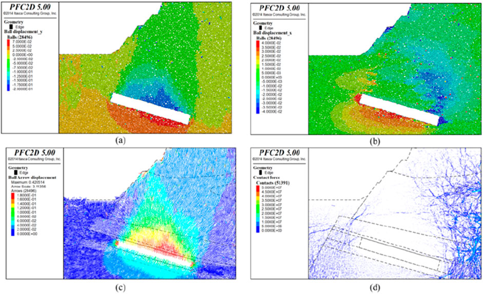
Figure 11. Simulation results after 4,000 excavation steps (a) vertical displacement field after mining disturbance, (b) horizontal displacement field, (c) displacement vector field, (d) local force chain field).
Following excavation, the computational analysis advanced to 6,000 steps. The vertical displacement of the rock-soil mass, as illustrated in Figure 12a, exhibits a maximum vertical displacement of 0.4 m at the roof. The horizontal displacement, as presented in Figure 12b, with significant horizontal displacements observed at the two sides of the working face, the central part of the floor, and the upper right corner of the roof, has a maximum horizontal displacement of 0.06 m. The displacement vector field, as depicted in Figure 12c, features a maximum displacement value of 0.35 m, and a maximum surface displacement of 0.1 m, accompanied by the emergence of ground cracks on the slope.
(5) Calculation after excavation for 10,000 steps
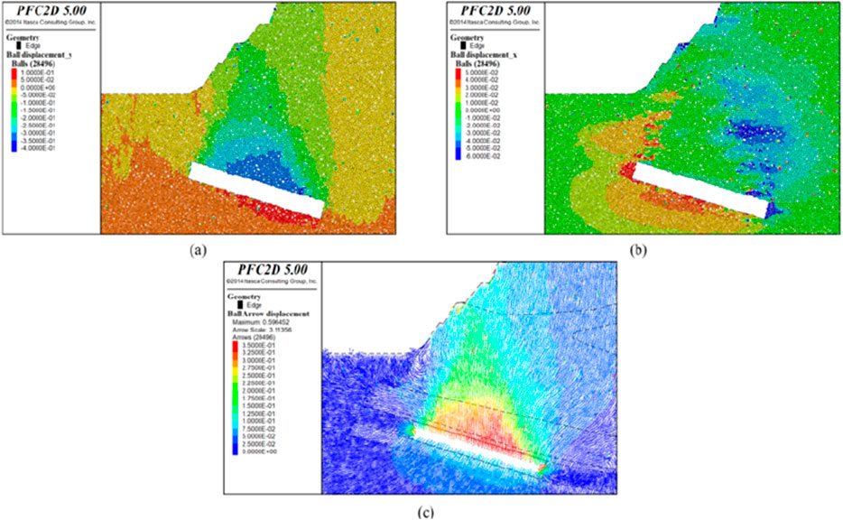
Figure 12. Simulation results after 6,000 excavation steps (a) vertical displacement field after mining disturbance, (b) horizontal displacement field, (c) displacement vector field).
Following the excavation, the simulation was run for 10,000 steps. The vertical displacement of the rock-soil mass is presented in Figure 13a, with a maximum vertical displacement at the roof of 1 m. The horizontal displacement is detailed in Figure 13b, with the maximum horizontal displacement at the two sides of the working face reaching 0.6 m. The displacement vector field, as illustrated in Figure 13c, features a maximum displacement value of 1 m, and a maximum surface displacement of 0.6 m, and ground cracks on the slope widening significantly. As a result of mining activities, significant displacement is observed in some particles on the slope of the overlying rock, as shown in Figure 13d. This occurs due to the slope’s large inclination angle, which, when combined with the disturbance from mining activities, compromises the stability of the rock-soil mass and results in local small-scale slope failures.
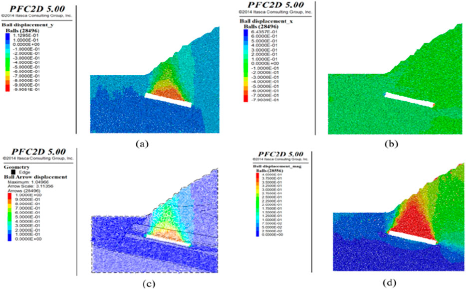
Figure 13. Simulation results after 10,000 excavation steps (a) vertical displacement field after mining disturbance, (b) horizontal displacement field, (c) displacement vector field, (d) displacement cloud map).
Following mining activities, the destruction field of the slope rock-soil mass is depicted in Figure 14. It is evident that the rock-soil mass situated above the goaf experiences destruction, with particle contacts transitioning from a parallel bonding model (depicted in green) to a linear contact model (depicted in red). As illustrated in Figure 15, subsequent to the roof collapse post-mining, a force chain arch structure emerges above the goaf. The strength of the force chains is indicated by varying colors within the figure, with blue representing the weakest and red the strongest force chains. It is observable that the robust force chains (red in the figure) constitute the backbone of the force chain arch, while the encircling weaker force chains offer supplementary support. Collectively, these two types of force chains establish the re-distributed force chain network within the goaf.
(6) Calculation after excavation for 20,000 steps
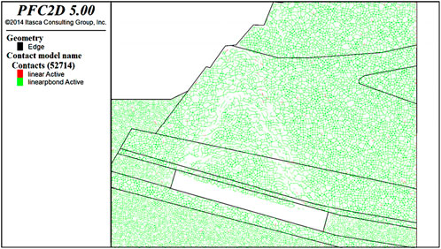
Figure 14. Post-mining disturbance failure field of potential sliding zone.
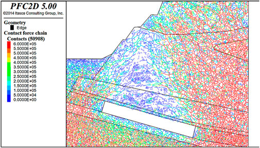
Figure 15. Local force chain field of potential sliding zone after mining disturbance.
Post-excavation, the simulation progressed to 20,000 steps. The vertical displacement of the rock-soil mass is presented in Figure 16a, where it is observed that the roof and the overlying rock have fully subsided into the goaf, with the maximum vertical displacement at the roof recorded as 11.9 m. The horizontal displacement field is detailed in Figure 16b, with significant horizontal displacements noted at the two sides of the working face and the overlying area, with the maximum horizontal displacement on the surface recorded at 0.2 m. The displacement vector field is portrayed in Figure 16c, with the maximum displacement magnitude peaking at 3.5 m, and a maximum surface displacement of approximately 2 m, accompanied by a significant widening of ground cracks on the slope.
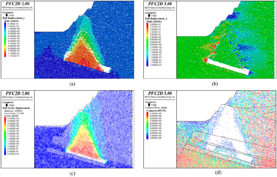
Figure 16. Simulation results after 20,000 excavation steps (a) vertical displacement field after mining disturbance, (b) horizontal displacement field, (c) displacement vector field, (d) local force chain field).
The force chain field subsequent to mining disturbance is presented in Figure 16d. At this stage, the force chain network of the immediate roof and the overlying rock layers has experienced numerous fractures, with the rock-soil mass that has subsided into the goaf undergoing breakage and reorganization of the force chain network, resulting in the formation of a novel accumulative-type force chain network.
5 Conclusion
(1) A structural mechanic’s model featuring a rock beam, with one end fixed and the other simply supported, was developed to analyze the mechanical behavior of the roof rock layer amidst mining operations. The deflection equation was formulated, and it was determined that the maximum deflection of the roof rock layer occurs at
(2) The numerical simulation results indicate that following the retreat of the fully mechanized caving face within a thick overburden coal mine, the deformation and destruction patterns of the overburden above the goaf in an inclined coal seam beneath the open-pit slope, as well as the roof collapse pattern and the movement and deformation patterns of the overlying strata, markedly differ from those observed in the mining of gently inclined or nearly horizontal coal seams. A distinct asymmetry is evident, characterized by a roof collapse pattern resembling an inverted “V”, meaning that the upper portion of the goaf roof experiences a violent and complete collapse, whereas the lower portion of the goaf is entirely filled with gob, resulting in minimal roof collapse. The roof undergoes a more comprehensive filling process, thereby maintaining the structural integrity of the overburden strata.
(3) Simulation of the excavation process reveals that during the initial phase of excavation, the displacement of the overburden slope’s rock and soil mass is minimal, and a force chain arch structure forms above the goaf, with stress fracturing and redistributing. With an increasing number of computational steps, the displacement of the overburden increases progressively, accompanied by localized sliding of the slope’s rock and soil mass. Ultimately, the overburden succumbs to the goaf, with the maximum vertical displacement of the roof amounting to 11.9 m and the maximum surface displacement being approximately 2 m. It is anticipated that during the retreat phase of the 021N2 fully mechanized caving face, surface fractures and the underground goaf are likely to create a through channel, leading to substantial air leakage within the goaf, thereby severely impacting the prevention and control of spontaneous combustion on the working face.
6 Discussion
(1) The step-based DEM simulations employed in this study efficiently capture granular system dynamics but do not account for viscoelastic and time-dependent rock mass behavior. This simplification may neglect long-term deformation processes like creep, which are essential for predicting overlying rock strata stability. Future work could incorporate viscoelastic models to address these limitations.
(2) While the study emphasizes potential hydrogeological impacts, it provides limited quantitative analysis of water movement and pore pressure. The current model does not simulate hydrogeological processes such as water infiltration and pore pressure changes. Future research could develop a coupled hydro-mechanical framework to better understand these interactions.
(3) The study utilizes idealized geological conditions and material properties. In reality, geological formations often exhibit greater heterogeneity and anisotropy. Incorporating detailed geological surveys and advanced imaging could enhance model realism.
(4) The focus on mechanical behavior means that other physical processes such as thermal effects and chemical weathering are not considered. These factors can influence rock mass stability. Future research could explore multi-physics coupling models for a more comprehensive understanding.
(5) The computational model relies on simplified particle interactions. Real rock masses possess complex particle shapes and bonding mechanisms. Including more realistic particle representations could improve simulation accuracy.
Data availability statement
The original contributions presented in the study are included in the article/supplementary material, further inquiries can be directed to the corresponding authors.
Author contributions
HC: Investigation, Methodology, Writing – original draft. ML: Conceptualization, Formal Analysis, Writing – review and editing. MX: Investigation, Software, Writing – original draft. MW: Conceptualization, Supervision, Writing – original draft. HT: Formal Analysis, Investigation, Writing – original draft. YQ: Investigation, Visualization, Writing – review and editing. QY: Conceptualization, Resources, Supervision, Writing – review and editing. MZ: Conceptualization, Resources, Writing – review and editing.
Funding
The author(s) declare that financial support was received for the research and/or publication of this article. This work was funded in part by the National Natural Science Foundation of China, grant number 51804052; Chongqing Municipal Key Projects for Innovation and Application Development, grant number CSTB2022TIAD-KPX0105; Research Projects of Chongqing Planning and Natural Resources Bureau, grant number KJ2022-044.
Conflict of interest
The authors declare that the research was conducted in the absence of any commercial or financial relationships that could be construed as a potential conflict of interest.
Generative AI statement
The author(s) declare that no Generative AI was used in the creation of this manuscript.
Publisher’s note
All claims expressed in this article are solely those of the authors and do not necessarily represent those of their affiliated organizations, or those of the publisher, the editors and the reviewers. Any product that may be evaluated in this article, or claim that may be made by its manufacturer, is not guaranteed or endorsed by the publisher.
References
Adajar, J., Ubay, I., Alfaro, M., and Chen, Y. (2020). Discrete element model parameters to simulate slope movements. Int. J. Geomate 18 (65), 192–199. doi:10.21660/2020.65.9424
Ahmad, T., and Zhang, D. (2020). A critical review of comparative global historical energy consumption and future demand: the story told so far. Energy Rep. 6, 1973–1991. doi:10.1016/j.egyr.2020.07.020
Akgoz, B., and Civalek, O. (2022). Buckling analysis of functionally graded tapered microbeams via Rayleigh-ritz method. Mathematics 10 (23), 4429. doi:10.3390/math10234429
An, S., Yuan, L., Xu, Y., Wang, X., and Zhou, D. (2024). Ground subsidence monitoring in based on UAV-lidar technology: a case study of a mine in the ordos, China. Geomechanics Geophys. Geo-Energy Geo-Resources 10 (1), 57. doi:10.1007/s40948-024-00762-0
Cao, P., Cheng, S., Lin, H., Wang, X., Li, M., and Chen, J. (2021). Dem in quantitative analysis of structural geomorphology: application and prospect. J. Geomechanics 27 (6), 949–962. doi:10.12090/j.issn.1006-6616.2021.27.06.077
Cao, Z., Yang, X., Li, Z., and Du, F. (2024). Evolution mechanism of water-conducting fractures in overburden under the influence of water-rich fault in underground coal mining. Sci. Rep. 14 (1), 5081. doi:10.1038/s41598-024-54803-5
Cheng, Z., Li, L., and Liu, J. (2018). Industrial structure, technical progress and carbon intensity in China’s provinces. Renew. and Sustain. Energy Rev. 81, 2935–2946. doi:10.1016/j.rser.2017.06.103
Cuong, T. V., Kawamoto, K., and Kien, T. T. (2022). Review on current situation of generation and management of coal ash in vietnam. Int. J. Geomate 22 (91), 62–69. doi:10.21660/2022.91.gxi316
Kang, H., Gao, F., Xu, G., and Ren, H. (2023). Mechanical behaviors of coal measures and ground control technologies for China’s deep coal mines - a review. J. Rock Mech. Geotechnical Eng. 15 (1), 37–65. doi:10.1016/j.jrmge.2022.11.004
Kien, T., and Lanh, P. (2021). Utilization of recycled coal mining waste for road foundation layers in vietnam. Int. J. Geomate 21 (87), 11–18. doi:10.21660/2021.87.j2229
Le, N. P., Khanh, N. B., and An, T. N. T. (2024). Flood inundation analysis in downstream of small hydropower plant: a case study in lang son Province, Vietnam. Int. J. Geomate 27 (123), 38–45. doi:10.21660/2024.123.4617
Li, Y., Pan, S., Ning, S., Shao, L., Jing, Z., and Wang, Z. (2022). Coal measure metallogeny: metallogenic system and implication for resource and environment. Sci. China-Earth Sci. 65 (7), 1211–1228. doi:10.1007/s11430-021-9920-4
Liu, H., Zhang, B., Li, X., Liu, C., Wang, C., Wang, F., et al. (2022). Research on roof damage mechanism and control technology of gob-side entry retaining under close distance gob. Eng. Fail. Anal. 138, 106331. doi:10.1016/j.engfailanal.2022.106331
Liu, X., Jin, Z., Jing, Y., Fan, P., Qi, Z., Bao, W., et al. (2021). Review of the characteristics and graded utilisation of coal gasification slag. Chin. J. Chem. Eng. 35, 92–106. doi:10.1016/j.cjche.2021.05.007
Ma, S., Qiu, H., Yang, D., Wang, J., Zhu, Y., Tang, B., et al. (2023). Surface multi-hazard effect of underground coal mining. Landslides 20 (1), 39–52. doi:10.1007/s10346-022-01961-0
National Bureau of Statistics of China (2024). Statistical bulletin on national economic and social development of the people's Republic of China in 2023. China Stat. (3), 4–21. doi:10.28655/n.cnki.nrmrb.2024.002126
Qian, M., and Xu, J. (2019). Behaviors of strata movement in coal mining. J. China Coal Soc. 44 (4), 973–984. doi:10.13225/j.cnki.jccs.2019.0337
Qu, J., Yang, W., Shen, J., Zhang, C., Wan, F., Ma, S., et al. (2024). Analysis of debris flow engineering treatment effect based on dem data preprocessing in small watershed: a case study of fangjiagou debris flow, zhangxian county. Hydrogeology and Eng. Geol. 51 (4), 206–219. doi:10.16030/j.cnki.issn.1000-3665.202211068
Song, Z., and Kuenzer, C. (2014). Coal fires in China over the last decade: a comprehensive review. Int. J. Coal Geol. 133, 72–99. doi:10.1016/j.coal.2014.09.004
Sun, B., Yuan, L., Zhang, P., and Wu, R. (2024). Study on the optic-electric perception experiment of overburden movement and separation evolution in the mining area under super-thick conglomerates. J. China Univ. Min. and Technol. 53 (5), 977–992. doi:10.13247/j.cnki.jcumt.20240162
Sun, Y., Xu, C., Zuo, J., Li, M., Shi, Y., and Zhou, Y. (2020). Mechanical model of rock strata continuous bending movement under non-uniform load in backfill mining. Coal Sci. Technol. 48 (9), 139–145. doi:10.13199/j.cnki.cst.2020.09.017
Wang, G., Xu, Y., and Ren, H. (2019a). Intelligent and ecological coal mining as well as clean utilization technology in China: review and prospects. Int. J. Min. Sci. Technol. 29 (2), 161–169. doi:10.1016/j.ijmst.2018.06.005
Wang, X., Wang, S., Peng, X., Ma, T., and Chen, B. (2022). Equivalent numerical simulation method and application in karst-induced collapse of overlying sandy stratum. Eng. Fail. Anal. 137, 106280. doi:10.1016/j.engfailanal.2022.106280
Wang, Z., Wang, A., and Guo, X. (2019b). The numerical simulation of space growth of bed separations under different horizontal overburden combinations. Geotechnical Geol. Eng. 37 (1), 347–357. doi:10.1007/s10706-018-0613-9
Wu, Q., Jiang, L., Wu, Q., Xue, Y., and Gong, B. (2018). A study on the law of overlying strata migration and separation space evolution under hard and thick strata in underground coal mining by similar simulation. Dyna 93 (2), 175–181. doi:10.6036/8678
Xie, C., Luo, Z., Jia, N., Yang, B., and Cheng, G. (2013). Safety roof cutting thickness in mining gently inclined and extremely thick ore body. J. Min. and Saf. Eng. 30 (2), 278–284.
Xiong, L., Tang, G., Yang, X., and Li, F. (2021). Geomorphology-oriented digital terrain analysis: progress and perspectives. J. Geogr. Sci. 31 (3), 456–476. doi:10.1007/s11442-021-1853-9
Yuan, C., Yuan, Z., Wang, Y., and Li, C. (2019). Analysis of the diffusion process of mining overburden separation strata based on the digital speckle correlation coefficient field. Int. J. Rock Mech. Min. Sci. 119, 13–21. doi:10.1016/j.ijrmms.2019.04.016
Zhang, G., Tao, G., Meng, X., Li, Y., Qu, Z., Xu, R., et al. (2022). Failure law of weak overburden stratum underlying extra thick alluvium. J. China Coal Soc. 47 (11), 3998–4010. doi:10.13225/j.cnki.jccs.2021.1994
Zhang, J., Li, X., Qin, Q., Wang, Y., and Gao, X. (2023). Study on overlying strata movement patterns and mechanisms in super-large mining height stopes. Bull. Eng. Geol. Environ. 82 (4), 142. doi:10.1007/s10064-023-03185-5
Zhang, M., Fan, J., Du, J., Jiang, D., Chen, J., Yuan, Q., et al. (2024). Experimental study on effects of load damage precursor information and response characteristic of gas-containing coal for mining safety based on acoustic emission. Process Saf. And Environ. Prot. 184, 184993–1010. doi:10.1016/j.psep.2024.01.057
Zhao, T., Liu, C., Yetilmezsoy, K., Zhang, B., and Zhang, S. (2017). Fractural structure of thick hard roof stratum using long beam theory and numerical modeling. Environ. Earth Sci. 76 (21), 751. doi:10.1007/s12665-017-7103-x
Zou, C., Xue, H., Xiong, B., Zhang, G., Pan, S., Jia, C., et al. (2021). Connotation, innovation and vision of carbon neutral. Nat. Gas. Ind. 41 (8), 46–57. doi:10.3787/j.issn.1000-0976.2021.08.005
Keywords: thick overburden roof, open-pit slope, PFC-2D simulation, stability analysis, coal mine safety
Citation: Chen H, Luan M, Xue M, Wang M, Tian H, Qu Y, Yuan Q and Zhang M (2025) Study on structural evolution law of overlying rock mass in fully mechanized top-coal caving face under open-pit slope with extremely thick and hard overburden. Front. Earth Sci. 13:1609397. doi: 10.3389/feart.2025.1609397
Received: 10 April 2025; Accepted: 05 June 2025;
Published: 30 June 2025.
Edited by:
Xin Yin, City University of Hong Kong, Hong Kong SAR, ChinaReviewed by:
Jinsong Fan, National University of Singapore, SingaporeArifuggaman Arif, Huaiyin Institute of Technology, China
Copyright © 2025 Chen, Luan, Xue, Wang, Tian, Qu, Yuan and Zhang. This is an open-access article distributed under the terms of the Creative Commons Attribution License (CC BY). The use, distribution or reproduction in other forums is permitted, provided the original author(s) and the copyright owner(s) are credited and that the original publication in this journal is cited, in accordance with accepted academic practice. No use, distribution or reproduction is permitted which does not comply with these terms.
*Correspondence: Qiang Yuan, cWlhbmd5dWFuQGNxdS5lZHUuY24=; Mingtian Zhang, Y29rZXhpYW90aWFuQDEyNi5jb20=