 Chao Tang1,2,3†
 Ke Du1,2,3*†Gongshuai Guan1,2,3†Xiangfu Gai1,2,3Guo Li1,2,3Qingsong Li1,2,3Lichao Wang1,2,3Hongguang Guo1,2,3Wenping Sun1,2,3Chao Gao1,2,3Weiwei Xu1,2,3Zhuoyuan Lu4
 Junwei Su5Dengke Liu5
- 1Daqing Oilfield Production Technology Institute, Daqing, China
- 2Heilongjiang Provincial Key Laboratory for Increasing Oil and Gas Reservoir Yield, Daqing, China
- 3State Key Laboratory of Continental Shale Oil, Daqing, China
- 4International School, Beijing University of Posts and Telecommunications, Beijing, China
- 5School of Human Settlement and Civil Engineering, Xi’an Jiaotong University, Xi’an, China
The reinjection of treated oilfield water into formations stands as one of the commonly employed methods in oilfield water injection development. However, certain treated waters contain a substantial number of suspended oil droplets, which can lead to the blockage of flow paths and pore channels. At present, there is a deficiency in experimental verification results regarding the reinjection of oily wastewater, and a lack of a reasonable explanation for the micro-mechanism underlying oil droplet migration. Consequently, in order to elucidate the distribution characteristics of oil droplets and the microscopic mechanism of oil droplet migration during the process of oilfield treatment water reinjection, a simulated oil and microfluidic chip were fabricated to conduct relevant experiments. The experimental results reveal that the particle size of oil droplets is the most crucial control indicator affecting reservoir blockage, with a porosity damage rate of 21.9% and a permeability damage rate of 20.9%. The results further indicate that large oil droplets directly block the pores, while small oil droplets blocking the pores exhibit two regional characteristics: saturated blockage and unsaturated blockage. Additionally, the numerical simulation results are in agreement with the experimental findings. This study offers a framework for the implementation of wastewater reinjection in oilfield operations.
1 Introduction
Subsurface energy extraction, particularly petroleum extraction, stands as one of the principal sources of energy supply on a global scale (Bai et al., 2024; He et al., 2025; Li et al., 2023; Liu et al., 2022b; Zhang et al., 2024). During the oil extraction process, which is a complex and multi-faceted operation, as the oilfield gradually enters the mid to late stage of development, various challenges begin to emerge (Huang et al., 2025; Li et al., 2025; Li et al., 2024). One of the significant issues that arise is the generation of a large amount of oily wastewater. This oily wastewater is a by-product of the extraction activities that take place within the oilfield. As the extraction progresses and the oil reserves start to deplete, the production and handling of this wastewater become increasingly prominent. The volume of oily wastewater continues to accumulate, posing a considerable challenge to the efficient management and sustainable development of the oilfield. In order to protect the environment, save water resources, and achieve sustainable development of oil fields, sewage reinjected technology is widely used in oil field development (English et al., 2016; Pang et al., 2023). Although injecting wastewater into the reservoir can indeed supply the necessary formation energy and subsequently enhance the oil recovery process, it is crucial to acknowledge that this practice can also cause substantial harm to the reservoir itself (Chakraborty et al., 2020; Li et al., 2016). The introduction of wastewater, which often contains various contaminants and high levels of salinity, can lead to a plethora of issues such as the reduction of permeability, alteration of rock properties, and potential damage to the reservoir’s natural fractures (Al Hadabi et al., 2016; Karami et al., 2023a; Zhu D. et al., 2024; Zhu J. Y. et al., 2024). These adverse effects not only pose challenges to the efficient extraction of oil but can also have significant environmental implications if not managed properly.
As the main storage site for petroleum resources, oil reservoirs play a crucial role in the entire petroleum extraction process. They possess complex geological conditions. The strata where they are located may vary significantly in lithology, porosity, and permeability, which are all factors that influence the storage and movement of oil (Oseguera and Aguilera, 2024; Qin et al., 2025; Qu et al., 2021; Youssif et al., 2024). Moreover, they have unique structures. Different geological forces during their formation have led to diverse reservoir shapes, such as anticlines, fault blocks, and lens-shaped bodies, each with its own characteristics affecting oil accumulation and production. Furthermore, oil reservoirs are highly sensitive to the injection water quality. The chemical composition, suspended solids content, and microbial activity of the injected water can have a substantial impact on the reservoir’s performance (Marchand et al., 2002; Sun et al., 2019). In order to ensure the continuous development of oil reservoirs, extremely high injection water quality was required (Karami et al., 2023b; Nasybullin et al., 2024; Parekh et al., 2024). However, some conventionally treated reinjection wastewater still contain suspended solids, dissolved salts, organic matter, heavy metals, and other components, which may trigger a series of physical, chemical, and biological reactions when in contact with reservoir rocks. These reactions may lead to a decrease in permeability and porosity of reservoir rocks, and even cause damage to the reservoir structure (Ma et al., 2024; Wilkinson et al., 2006). In addition, parameters such as temperature, pressure, and flow rate of reinjection wastewater may also have adverse effects on the reservoir, exacerbating reservoir damage (Fu et al., 2021; Liu et al., 2022a; Liu et al., 2021). Among these impurities, small oil droplets in sewage are an undeniable factor. Due to the difference in viscosity between oil and water, oil droplets may accumulate continuously, leading to blockage of the flow channel and affecting the recovery rate. Therefore, it is an important scientific issue to clarify the impact of oil droplets in sewage on the seepage channel.
Domestic and foreign scholars have conducted extensive and in-depth research on the damage of reinjected wastewater to oil reservoirs at present (Dutton et al., 2016). They have analyzed the damage mechanism from different perspectives, explored the influencing factors, proposed corresponding prevention and control measures (Liu et al., 2024; Pang et al., 2023; Tang et al., 2021). However, the situation is rather complex. Due to the remarkable diversity and intricate complexity of reservoir conditions, which can vary significantly from one geological formation to another, encompassing differences in porosity, permeability, and the presence of various minerals and impurities. Moreover, there are also notable differences in the composition of reinjected wastewater (Karuppasamy et al., 2024; Martwong et al., 2024; Mathew et al., 2024). This wastewater can contain a wide range of substances such as salts, organic compounds, and suspended particles, with their concentrations and types fluctuating depending on multiple factors (Hussain et al., 2025; Shah et al., 2024; Wu et al., 2025). As a result, there are still numerous controversies and many unsolved mysteries regarding the micro damage of reinjected wastewater to the reservoir. In particular, the micro blockage mechanism of oil droplets remains a subject of intense debate and investigation. Understanding this mechanism is crucial for optimizing oil production processes and ensuring the long-term efficiency and sustainability of reservoir operations.
In order to comprehensively and accurately clarify the blockage mechanism of oil-bearing wastewater to the reservoir, this work carried out a series of in-depth investigations. Specifically, real reinjected wastewater samples were carefully collected from different blocks of XX oilfield. The oil droplet concentration, particle size, and viscosity of these samples were meticulously measured using advanced and precise experimental techniques and equipment. Based on the obtained and highly reliable data, simulated oil was meticulously manufactured, taking into account various factors such as the specific composition and physical properties of the real wastewater. This simulated oil was then used to conduct a series of relevant experiments. In these experiments, self-developed large-sized microfluidic chips played a crucial role. These chips, with their unique design and functionality, provided a favorable environment for observing the behavior of oil droplets under controlled conditions. During the injection process, the microscopic migration behavior of oil droplets was carefully observed and statistically analyzed. To achieve this, a combination of mechanical analysis methods was employed. These methods allowed for a detailed understanding of the forces acting on the oil droplets and their movement patterns. Hopefully, this work holds significant value as it can provide comprehensive theoretical guidance for oilfield reinjection wastewater work.
2 Methodology
2.1 Detection of oil droplet concentration, size and viscosity in reinjected wastewater
The real reinjection wastewater of X1, X2 and X3 well studied in this research is collected from different block of XX oilfield. The Perkin Elmer LS55 spectrophotometer was used in this experiment to detect the oil droplet concentration. The wavelength accuracy of the instrument is ±1 nm, wavelength repeatability is ±0.5 nm, bandwidth: excitation slit 2.5–15 nm, emission slit 2.5–20 nm, scanning speed is 10–1,500 nm/min, and the adjustment step is 1 nm.
The oil droplet size tests were finished by using a microfluidic chip and a high-resolution camera, and the method is direct observation. The main procedure contains: (1) Inject the wastewater sample into the microfluidic chip using a pressure pump until the solution fills the pore channels; (2) Use a high-resolution camera to capture the microfluidic chip, and extract oil droplet information to obtain the scale distribution of the oil droplet area by using image segmentation technology; (3) Combine with the depth of the microfluidic chip channel to calculate the size distribution of oil droplets.
This experiment utilized an NDJ-5S digital viscometer to measure the viscosity. The range of this instrument is 1–200 mPa s, and the No. 1 rotor used is a dedicated oil phase rotor. If the percentage displayed on the viscometer is less than 10%, which indicates that the viscosity of the measured object is not within the measurement range of the rotor. Then, re-measure the viscosity until the percentage displayed on the viscometer is between 10% and 90%.
2.2 Microfluidic chip design
In order to clarify the damage degree and micro-mechanism of reinjection wastewater to oil layers, a microfluidic chip with a droplet generator was designed (Figure 1), which size is 15 × 15 cm and shooting interval is 1 s. It is worth noting that the chip possess the similar porosity and permeability as the XX oilfield. By using a self-designed oil droplet generator and controlling the flow rate, a simulated oil wastewater that meets the actual conditions of the reservoir is obtained. This device controls the concentration and size of oil droplets by controlling the relative velocity of the water and oil phases. Using image analysis methods, the micro oil water distribution characteristics are statistically analyzed.
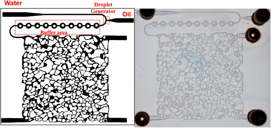
Figure 1. The microfluidic chip with generator used in this experiment (The left is illustration model, and the right is real product).
2.3 Sewage reinjected experiments
Based on the concentration, particle size, and viscosity information of X1, X2, and X3 well extraction water samples, the simulate wastewater, using mineral oil, aviation kerosene, and anhydrous kerosene, was manufactured to conduct sewage reinjected experiments. In order to clarify the degree of influence of oil droplets on reservoir physical properties and provide guidance for actual on-site wastewater reinjection work, relevant experiments were also conducted with different particle size, viscosity, and concentration of oil droplets in reinjection wastewater. For the oil droplets size, set initial injection speed to 2 μL/min, oil droplets concentration of 300 mg/L and viscosity of 25 mPa s, a series experiment with oil droplets size from 10 μm to 50 μm was studied; For oil droplets concentration, set initial injection speed of 2 μL/min, oil particle size of 30 μm and oil viscosity of 25 mPa s, a series experiment with oil droplets concentration from 100 mg/L to 500 mg/L was studied; For oil droplets viscosity, set initial injection speed to 2 μL/min, oil particle size to 30 μm, and oil droplets concentration to 300 mg/L. a series experiment with oil droplets viscosity from 5 mPa s to 30 mPa s was also studied.
2.4 Fundamentals of numerical simulation for oily wastewater reinjection
In order to simultaneously consider the fluid flow process inside the fracture and matrix, this project plans to use the DBS (Darcy Brinkman Stokes Equation) framework to describe the flow inside the fracture and the seepage inside the matrix (Lu et al., 2023; Martys et al., 1994; Soulaine and Tchelepi, 2016; Xie et al., 2008; Zhang et al., 2025). Note that the DBS framework was selected because it models coupled free flow in fractures and Darcy flow in porous media. The mass conservation equation of a fluid can be expressed as Equation 1:
where
where V-total volume/m3;
where
The following equation is used for tracking oil droplets, and the relevant parameters are determined using physical simulation experimental results as Equation 5:
where Co-oil droplet concentration/%; D-oil droplet dispersion coefficient. On the right side of the equation is the variation of oil saturation in pores over time, which can be described by the following Equation 6:
where So-current oil retention/%; Soe-maximum oil retention;
3 Results and discussion
3.1 Oil droplet properties
For the reinjection wastewater of X1, X2, and X3 wells, the oil droplet concentration is 324.68 mg/L, 463.82 mg/L, and 241.19 mg/L, respectively (Figure 2a), and the oil droplet size is mainly distributed between 13–46 μm, 13–45 μm, and 11–39 μm, the average size is 22.3 μm, 24.5 μm, and 18.3 μm, respectively (Figure 2b), generally concentrated between 10–25 μm. The viscosity of the oil phase is 20.13 mPa s, 22.87 mPa s, and 25.87 mPa s, respectively (Figure 2c). The detailed experimental results clearly show that the X2 sample exhibits the highest oil droplet concentration and average radius among all the samples analyzed in this study. Specifically, the data reveals that the X2 sample has a significantly larger number of oil droplets per unit volume and these droplets possess a relatively greater average size in terms of radius, compared to the samples obtained from the other wells. This strong indication leads to the conclusion that the reinjection wastewater of X2 well is, without a doubt, more polluted than that of the other wells involved in this comprehensive study. Such a finding emphasizes the need for more stringent treatment measures and closer monitoring of the X2 well’s wastewater to ensure environmental safety and regulatory compliance.
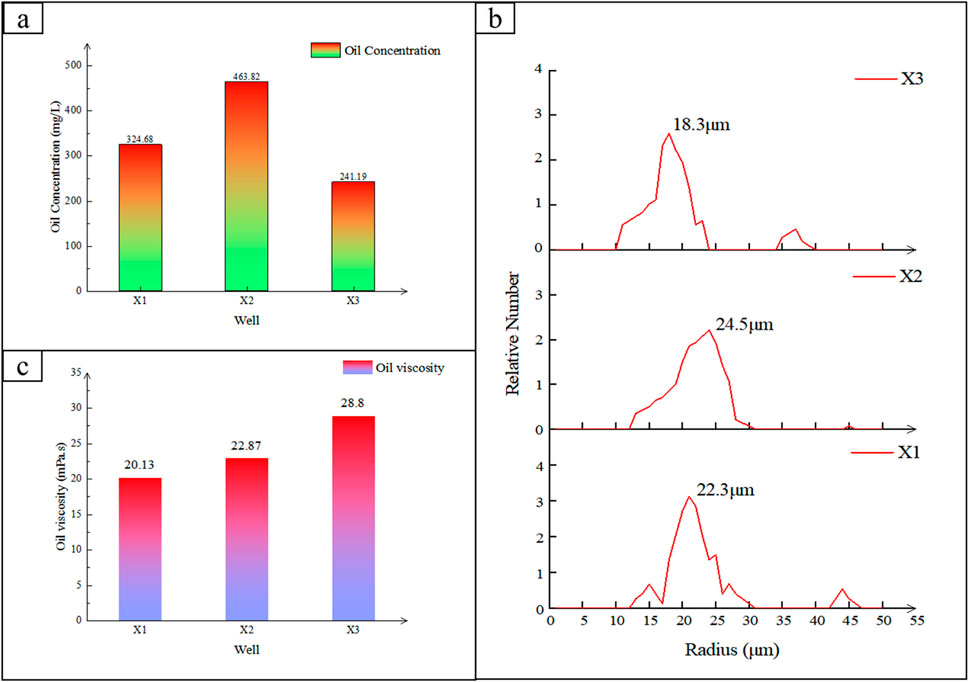
Figure 2. (a) Oil droplet concentration, (b) oil droplet size distributions, (c) and oil droplet viscosity.
3.2 The influence of oil droplet properties on reservoir properties
According to the comprehensive basic data of numerous real samples collected from diverse sources, a series of different simulated wastewaters was meticulously manufactured. These real samples covered a wide range of industries and environmental conditions, ensuring the representativeness of the data. By leveraging this detailed information, the simulated wastewaters were carefully designed to mimic various potential pollutants and contamination levels. The primary objective of this process was to conduct an in-depth study on the damage degree that these wastewaters could potentially cause to the microfluidic chips. This research is of great significance as it can provide valuable insights into the durability and performance of microfluidic chips in real-world scenarios, helping to improve their design and application. As the oil droplet concentration increase from 100 mg/L to 500 mg/L, the porosity decrease from 17.20% to 16.03%, the ratio of permeability and initial permeability (K/K0) decrease from 0.159 to 0.143 (Figure 3a). Keeping the oil droplet concentration and viscosity unchanged, the porosity decrease from 19.86% to 15.50%, and the K/K0 decrease from 0.181 to 0.143 (Figure 3b), when the oil droplet average size increase from 10 μm to 50 μm. Besides, with the oil droplet concentration and average size unchanged, the porosity decrease from 27.12% to 25.57%, and the K/K0 decrease from 0.978 to 0.872 (Figure 3c), when the oil droplet viscosity increase from 5 mPa s to 50 mPa s. As the oil droplet size increases, both porosity and permeability show a cliff like decline with porosity decreased nearly 21.9% and permeability decreased nearly 20.9% (that is, 20.9% original permeability was failed) (Figure 3b). The experimental results clearly indicate that among various factors, the size of oil droplets is the most important indicator significantly affecting the degree of reservoir blockage. When compared with the other two aspects, namely, the concentration and viscosity of oil droplets, the impact of droplet size becomes particularly prominent. Regarding the effect of concentration, when the concentration of oil droplets changes, it leads to a certain degree of decrease in porosity and permeability. Specifically, the porosity decreased by 6.8% and the permeability decreased by 9.9%. As for the viscosity, its change also has an impact on the reservoir properties. In this case, the porosity decreased by 5.7% and the permeability decreased by 9.3%. However, all these effects are less significant compared to the influence exerted by the size of oil droplets.
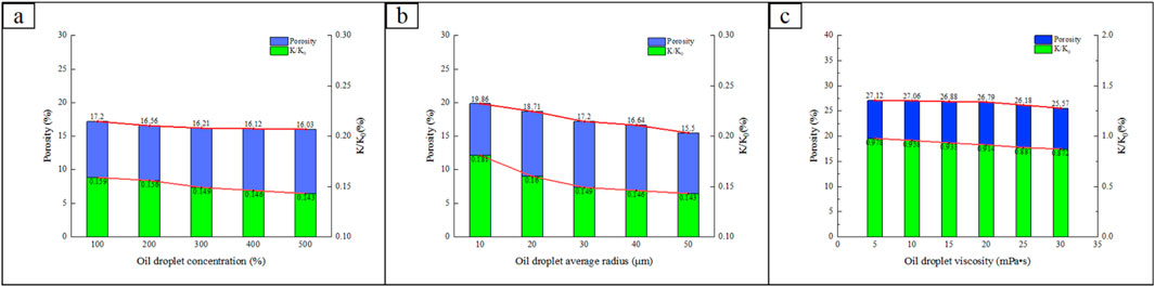
Figure 3. Porosity and permeability changes verses (a) oil droplet concentration; (b) oil droplet average radius; (c) oil droplet viscosity.
3.3 The spatial distribution state of oil droplet blockage
The oily wastewater position of different injection status have also been researched (Figure 4). As the low oil concentration in wastewater and high dynamic water conditions at the beginning of injection, the oil in wastewater was generally carried to the end of wellhead, little was left in the pores (Figure 4b). However, with the injection continued, more and more oil left in the pores, resulting pore blockage (Figure 4c). The experimental results clearly indicate that during the process of expanding outward from the wellhead, an increasingly larger number of pores are gradually blocked by oil - occurs mainly because of the strong dynamic effect in the vicinity of the wellhead. As the oil starts its outward expansion, it exerts a significant pressure and flow impact near the wellhead area. This strong dynamic force not only causes the oil to spread more rapidly but also leads to the gradual plugging of a growing quantity of pores. The reason for this is that the dynamic effect near the wellhead is so intense that it disrupts the normal flow and distribution of fluids within the pores, making it more difficult for them to remain unblocked. As a result, more and more pores become obstructed by the flowing oil, which has a considerable impact on the overall performance and behavior of the system.
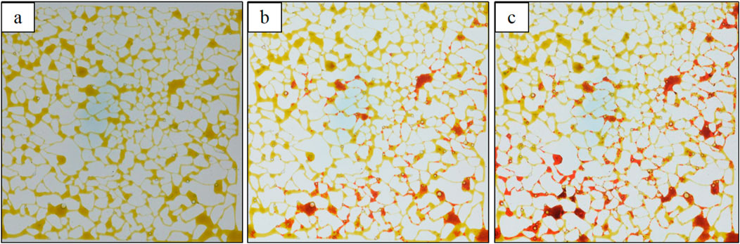
Figure 4. The distribution map of oil in microchips, picture (a–c) represent different injection time, respectively are 0 s, 300 s, and 600 s. The injection direction is lower right to top left.
The distribution of oil droplets in the pores and the distribution of blockage positions can be further divided into large oil droplets and small oil droplets, with some differences between the two. Figure 5 shows the characteristics of oil droplets blocking pore channels. From a microscopic perspective, large oil droplets are directly trapped by the surrounding throats, remained in the pores and kept static over time. However, the seepage characteristics of small oil droplets are different from those of large oil droplets. As shown in Figures 5c,d, small oil droplets move into the pores, continuously coalesce in the pores, eventually form blockages at the throat junction. The experimental results clearly indicate the following two distinct characteristics of small oil droplets. Firstly, local aggregation of small oil droplets occurs under certain conditions. As these small oil droplets gradually come together, they will form relatively large oil droplets. With the continuous growth and accumulation of these large oil droplets, they will eventually block the pores. This blockage can have a significant impact on the flow and distribution of fluids within the porous medium. Secondly, the continuous aggregation of small oil droplets does not stop at just forming large oil droplets. Instead, they further accumulate and form large oil blocks. These large oil blocks, when present at the pore throat, will cause a capillary effect. This capillary effect can lead to a decrease in the permeability of the porous medium and ultimately result in droplet blockage, which can severely restrict the flow of fluids through the pores.
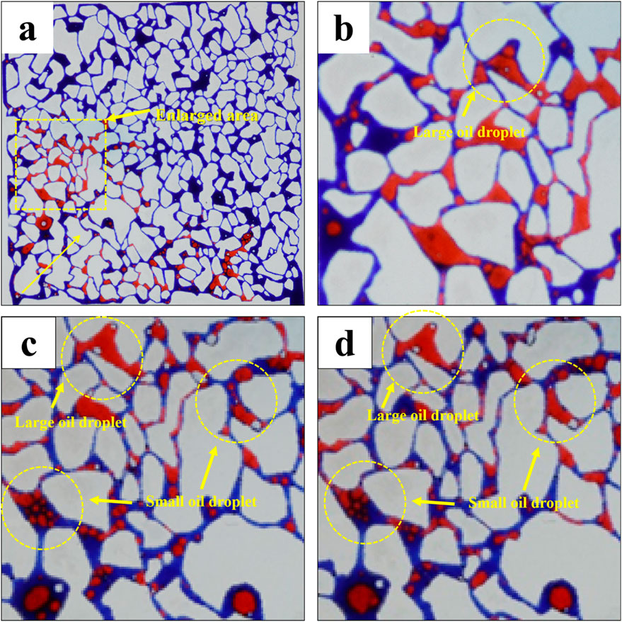
Figure 5. (a) Spatial distribution map of large oil droplets and water. (b) Migration characteristics of large oil droplets in pores at 300 s. (c) Migration characteristics of oil droplets in pores at 600 s. (d) Migration characteristics of oil droplets in pores at 900 s.
3.4 Microscopic aggregation state of small oil droplets
The above research has shown that large oil droplets can directly block pores, while small oil droplets accumulate to form large oil droplets that block pores. In order to clarify the characteristics of small oil droplet accumulation and blockage mechanism, a separate experiment on small oil droplet of wastewater was conducted. The result is shown in Figure 6 and the result indicate that small oil droplets blocking the pore channel can exhibit two regional characteristics: saturated blockage–regional occupancy (Zone A in Figure 6) and unsaturated blockage–rarely occupancy (Zone B in Figure 6). In a saturated blockage area, the process of oil droplet coalescence is a continuous one. Oil droplets, under the influence of various factors such as local pressure and flow conditions, continuously aggregate and merge with one another. As this coalescence progresses, they gradually form large blocks of oil. This formation has a significant impact on the pore structure. Consequently, the throats within the medium become occupied by water, while the pores are occupied by oil. Eventually, a blockage retention zone is formed. The motion of the saturated clogged boundary fluid exhibits a specific characteristic: it is perpendicular to the oil-water interface direction. In this region, there exists a well-defined clogging retention zone. Within this zone, the moving fluid does not come into direct contact with the oil-water interface. This lack of contact is due to the presence of the large oil blocks that act as a barrier. Ultimately, the channels within the saturated zone are completely blocked by oil. Once the channels are blocked, the fluid present in this area loses its mobility and does not participate in the overall movement within the system. The distribution of oil and water in the saturated retention area bears a resemblance to that of large oil droplet blockage. In both cases, oil accumulates in certain regions, creating a distinct pattern of distribution. To address this blockage issue, the main approach lies in reducing the interfacial tension. By decreasing the interfacial tension, the interaction between oil and water can be modified, which may potentially lead to the mobilization of the blocked fluid and a reduction in the blockage effect.
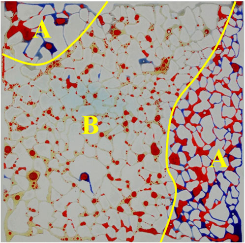
Figure 6. The spatial distribution of small oil droplet blockage after water flooding. The injection direction is lower right to top left. Blue: water; Red: oil; Yellow: Test blockage water.
However, in the unsaturated blockage area (Zone B in Figure 6), a series of complex physical phenomena occur. Oil droplets possess a certain affinity for the pore wall and tend to adsorb firmly on it. Once adsorbed, they remain in a static state, almost as if they are “anchored” to the pore surface. Meanwhile, as water moves through the connected pores, it exerts a significant influence on the pore characteristics. The water flow gradually erodes and displaces the fine particles or residues within the pores, causing the effective radius of the pores to decrease. This reduction in pore radius leads to an increase in the resistance encountered by the fluid as it passes through. The movement of fluids in this area is parallel to the oil-water interface. The moving fluid, mainly water in this case, comes into direct contact with the oil. This contact is not a simple physical encounter but involves various interactions, such as molecular diffusion and surface tension effects. The situation is further complicated by the comparison between the non-clogged saturated region and the clogged saturated region. The non-clogged saturated region has stronger dynamics compared to the clogged saturated region. In the non-clogged region, the hydrodynamic conditions are more favorable for fluid flow. Small droplets in this region will be continuously carried downstream by water. The continuous water flow acts as a driving force, pushing the small droplets along. As this process persists, severe blockage gradually forms away from the wellhead. Given the challenges posed by these phenomena, the main way to remove blockages is through emulsification. Emulsification can effectively break down the oil droplets, reducing their size and altering their physical properties. This, in turn, helps to improve the fluidity of the mixture and alleviate the blockage problem.
3.5 Analysis of micromechanical mechanisms
As the movement mechanism of oil droplets in the blockage retention area remains uncertain, further in-depth studies have been carried out. These investigations have revealed that the blockage retention zone is a distinct region characterized by fluid retention between pores where fluid movement is present and oil blockage positions are formed due to capillary blockage effects. Within this zone, the movement of the fluid is either significantly slowed down or completely stagnant, creating a complex environment that impacts the overall behavior of the oil droplets. The findings highlight the importance of understanding the dynamics of fluid retention and movement in porous media, as they play a crucial role in various applications such as enhanced oil recovery and contaminant transport in subsurface environments (Figure 7a). Due to the fluid in the blockage retention zone being in a stagnant state, its movement is extremely limited. In such a situation, for the unblocking agent to reach the oil-water interface and successfully achieve the unblocking effect, it is essential that it can pass through this particular area. As a result, a certain level of diffusion ability of the chemical agent becomes a necessity. Besides, this area serves as an important location where water type mismatch often leads to the precipitation of substances such as CaCO3, which can subsequently block pores. This blockage poses a significant challenge as it makes it even more difficult for oil droplet macromolecular surfactants to pass through. The presence of these precipitates not only narrows the available pathways but also changes the physical and chemical properties of the environment, further complicating the passage of the surfactants. In this area, the requirements for fluid diffusion are quite specific and need to be met. The diffusion process must overcome the resistance caused by the stagnant fluid and the precipitated substances. It requires a carefully balanced combination of factors, including the chemical properties of the unblocking agent, the physical characteristics of the blockage retention zone, and the interaction between different chemical components in the system, to ensure effective fluid diffusion and ultimately successful unblocking.
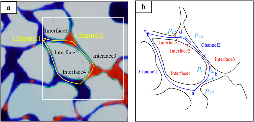
Figure 7. (a) The original characteristics of saturation retention (or large oil droplet blockage); (b) Mechanical analysis diagram.
Figure 7b is a schematic diagram of the mechanical analysis of the saturated retention region, where the mechanical characteristics of the interface in Channel 1 can be represented as Equation 7:
The mechanical characteristics of the interface in channel 2 can be expressed as Equation 8:
The utilization conditions of oil in channel 2 can be expressed as Equations 9, 10:
Therefore, through comprehensive mechanical analysis, it is clear that increasing the viscosity of the displacement fluid plays a crucial role in reducing oil droplet blockage. A higher viscosity helps to better carry and disperse the oil droplets, preventing them from aggregating and causing blockages. Meanwhile, increasing the displacement speed also has significant benefits. A faster displacement speed can create stronger shearing forces, which can break up potential aggregates of oil droplets more effectively and maintain a more stable flow pattern, thus contributing to the reduction of oil droplet blockage. Moreover, minimizing the interfacial tension between oil and water phases offers significant advantages. A reduced interfacial tension facilitates the emulsification process, enhancing phase miscibility while mitigating the risk of distinct interfacial boundaries where oil droplets may coalesce and obstruct flow pathways. Collectively, these mechanisms—including enhanced displacement fluid viscosity, optimized displacement velocity, and reduced oil-water interfacial tension—demonstrate substantial efficacy in preventing oil droplet accumulation and subsequent flow blockage.
3.6 Oil droplet blockage based on numerical calculation
Based on the comprehensive and detailed experimental results, further numerical simulation calculations were meticulously carried out. These calculations play a crucial role in deepening our understanding of the complex physical processes involved. The results vividly show that the retention of oil in the oil bearing area exhibits a distinct pattern in relation to the distance from the wellhead. Specifically, it is lower near the wellhead, as clearly illustrated in Figure 8. This phenomenon can be ascribed to the initially high energy and flow dynamics in the vicinity of the wellhead, which preclude excessive oil accumulation. As we move away from the wellhead, the situation changes significantly. The accumulation of oil continues to increase steadily. This progressive accumulation can be understood as a result of the decreasing flow velocity and the changing pressure distribution in the reservoir. Eventually, the oil accumulation crosses the oil front, at which point the retention rapidly decreases. This rapid decline can be related to the sudden change in the flow characteristics and the interaction with the surrounding rock matrix. After continuous injection for 180 days, a detailed analysis of the spatial distribution of oil droplets reveals that they are mainly concentrated near the well. There is relatively little radial variation in their distribution. This spatial localization is a result of the combined effects of fluid flow, reservoir heterogeneity, and the interaction between the injected fluid and the existing oil. The blockage of oil droplets, on the other hand, is predominantly located at the far end of the reservoir. This is mainly due to capillary blockage, which occurs when the small pores and throats in the reservoir are filled with oil droplets, impeding further fluid flow. It is noteworthy that the velocity of the fluid near the wellhead is relatively better, and the blockage is relatively small. This favorable flow condition near the wellhead is beneficial for the efficient injection and production processes. The simulation results are in excellent agreement with the experimental phenomena, providing strong validation for the accuracy and reliability of the numerical simulation model. This consistency not only confirms the validity of the simulation approach but also provides a solid basis for further investigations and applications in the field of oil reservoir engineering.
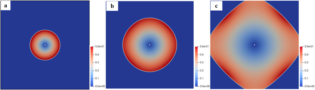
Figure 8. Blockage of oil droplets within (a) 30 days, (b) 60 days, and (c) 180 days.
3.7 Implications for field practice
Herein, the obtained findings provide critical operational guidance for wastewater reinjection management. Given the dominant role of oil droplet size (particularly >30 μm) in causing 21.9% porosity damage (viz., originally 21.9% porosity was disappeared), field operations should prioritize installing real-time droplet size monitors and centrifugal separators at reinjection wellheads to eliminate large droplets. The identified dual blockage mechanisms - direct pore blocking by large droplets and progressive clogging through small droplet coalescence - demand differentiated treatments: low-interfacial-tension surfactants near injection zones to mobilize trapped oil, and emulsifiers in distal regions to prevent throat blockage by migrating microdroplets. Numerical modeling validated by microfluidic experiments further suggests maintaining injection rates above 2 μL/min to suppress small droplet deposition while avoiding viscosity mismatches that exacerbate retention. Field-specific water quality thresholds should be established based on reservoir pore-throat distributions, with stricter oil concentration limits (<200 mg/L) for low-permeability formations. Integrating the calibrated DBS model with production data enables predictive maintenance planning to balance pretreatment costs against long-term productivity losses.
4 Conclusion
This study systematically elucidates the microscopic mechanisms underlying formation damage induced by oil-bearing wastewater reinjection through an integrated approach combining microfluidic experimentation and numerical simulation, from which the following key conclusions are derived:
The mean oil droplet concentration in the X1, X2, and X3 wastewater samples was quantified as 343.21 mg/L. The particle size distribution exhibited a predominant range of 10–25 μm. Furthermore, the measured average viscosity was determined to be 23.93 mPa s. Based on these analytical results, the simulated wastewater formulation was subsequently prepared.
The droplet size of oil significantly impairs pore permeability. Larger oil droplets can directly occlude pores and flow channels. Furthermore, when smaller oil droplets are introduced, they coalesce with larger droplets, leading to substantial reservoir blockage. Experimental results demonstrate that oil droplets with a particle size of 50 μm cause a porosity impairment rate of 21.9% and a permeability damage rate of 20.6%. The influence of oil droplet concentration is comparatively negligible, while the viscosity of oil droplets exhibits minimal impact.
The expansion of large wellhead-originated oil droplets progressively obstructs pore channels. Small oil droplets exhibit distinct behaviors: the non-obstructed saturated zone shows higher dynamic activity than oil-clogged regions, with hydrodynamic transport prevailing in non-saturated areas, while saturated zones experience complete pore occlusion. Effective mitigation strategies include increasing displacing fluid viscosity, enhancing displacement velocity, and reducing oil-water interfacial tension.
The numerical simulation results demonstrate that an increase in oil concentration leads to a significant rise in both the blockage radius and the degree of blockage. Oil droplet accumulation primarily occurs at the distal end, whereas the fluid velocity near the wellhead remains more favorable, exhibiting relatively minor blockage.
Data availability statement
The original contributions presented in the study are included in the article/supplementary material, further inquiries can be directed to the corresponding author.
Author contributions
CT: Writing – original draft, Conceptualization, Resources. KD: Funding acquisition, Writing – review and editing, Conceptualization. GG: Investigation, Data curation, Methodology, Writing – review and editing. XG: Writing – review and editing, Validation, Investigation. GL: Writing – review and editing, Investigation, Resources. QL: Software, Data curation, Writing – review and editing. LW: Writing – review and editing, Visualization, Methodology. HG: Investigation, Methodology, Writing – review and editing. WS: Writing – review and editing, Resources, Data curation. CG: Investigation, Writing – review and editing, Resources. WX: Conceptualization, Writing – review and editing, Data curation. ZL: Investigation, Writing – review and editing. JS: Writing – review and editing, Formal Analysis. DL: Conceptualization, Writing – review and editing.
Funding
The author(s) declare that financial support was received for the research and/or publication of this article. This work was supported by an Oilfield project of Field technical experiment of comprehensive treatment on well with a substandard amount of injection (No. DQP-2021-CYGC-XCSY-001). This work was also supported by Open Fund of Key Laboratory of Coal Resources Exploration and Comprehensive Utilization (Nos. KF2020-2, and KF2019-1), the Open Fund of Shaanxi Key Laboratory of Petroleum Accumulation Geology (No. PAG-201901), National Science and Technology Major Project (No. 2016ZX05047-003-005), and National Natural Science Foundation of China (Nos. 11872295 and 41702146).
Conflict of interest
Authors CT, KD, GG, XG, GL, QL, LW, HG, WS, CG, and WX are employed by Daqing Oilfield Production Technology Institute.
The remaining authors declare that the research was conducted in the absence of any commercial or financial relationships that could be construed as a potential conflict of interest.
Generative AI statement
The author(s) declare that no Generative AI was used in the creation of this manuscript.
Publisher’s note
All claims expressed in this article are solely those of the authors and do not necessarily represent those of their affiliated organizations, or those of the publisher, the editors and the reviewers. Any product that may be evaluated in this article, or claim that may be made by its manufacturer, is not guaranteed or endorsed by the publisher.
References
Al Hadabi, I., Sasaki, K., and Sugai, Y. (2016). Effect of kaolinite on water-in-oil emulsion formed by steam injection during tertiary oil recovery: a case study of an Omani heavy oil sandstone reservoir with a high kaolinite sludge content. Energy Fuels 30 (12), 10917–10924. doi:10.1021/acs.energyfuels.6b01822
Bai, X., Li, J., Liu, X., Wang, R., Ma, S., Yang, F., et al. (2024). Evolution of the anisotropic thermophysical performance for low-maturity oil shales at an elevated temperature and its implications for restoring oil development. Energy Fuels 38 (16), 15216–15224. doi:10.1021/acs.energyfuels.4c02964
Chakraborty, S., Govindarajan, S. K., and Gummadi, S. N. (2020). Numerical modeling on the influence of effective porosity, microbial kinetics, and operational parameters on enhanced oil recovery by microbial flooding within a sandstone formation. Spe J. 25 (6), 2932–2961. doi:10.2118/200639-pa
Dutton, A. A., Macciò, A. V., Dekel, A., Wang, L., Stinson, G., Obreja, A., et al. (2016). NIHAO IX: the role of gas inflows and outflows in driving the contraction and expansion of cold dark matter haloes. Mon. Notices R. Astronomical Soc. 461 (3), 2658–2675. doi:10.1093/mnras/stw1537
English, K. L., Redfern, J., Corcoran, D. V., English, J. M., and Cherif, R. Y. (2016). Constraining burial history and petroleum charge in exhumed basins: new insights from the Illizi Basin, Algeria. Aapg Bull. 100 (4), 623–655. doi:10.1306/12171515067
Fu, S. S., Fang, Q., Li, A. F., Li, Z. P., Han, J. L., Dang, X., et al. (2021). Accurate characterization of full pore size distribution of tight sandstones by low-temperature nitrogen gas adsorption and high-pressure mercury intrusion combination method. Energy Sci. Eng. 9 (1), 80–100. doi:10.1002/ese3.817
He, B., Xie, L., Liu, X., Liu, J., and Elsworth, D. (2025). Mechanistic controls on permeability evolution in thermally-upgraded low-maturity oil shales: application of machine learning outputs. Unconv. Resour. 6, 100133. doi:10.1016/j.uncres.2024.100133
Huang, S., Liu, D., Gomez-Rivas, E., Griera, A., Gan, Q., Wang, M., et al. (2025). Experimental insights into the nucleation and propagation of hydraulic fractures in anthracite coalbed methane reservoirs. Earth Energy Sci. doi:10.1016/j.ees.2025.01.002
Hussain, Z., Saleem, A., and Gao, L. Z. (2025). From waste to innovation: silver-doped silicate ink coating from waste coal fly ash for hydrophobic antimicrobial fabric and water-oil separation. Waste Manag. 194, 238–248. doi:10.1016/j.wasman.2025.01.021
Karami, M., Sedaee, B., and Nakhaee, A. (2023a). Effect of different injection fluids scenarios on swelling and migration of common clays in case of permeability variations: a micromodel study. J. Petroleum Explor. Prod. Technol. 13 (8), 1761–1787. doi:10.1007/s13202-023-01628-z
Karami, M., Sedaee, B., and Nakhaee, A. (2023b). Investigating different fluids and injection patterns on the effect of reservoir rock quality alteration due to swelling and migration of clay minerals at carbonate reservoirs. J. Energy Resour. Technology-Transactions Asme 145 (10). doi:10.1115/1.4062190
Karuppasamy, K., Mayyas, A., Alsheinat, E., Hassan-Beck, H., and Alfantazi, A. (2024). Exploring lithium extraction technologies in oil and gas field-produced waters: from waste to valuable resource. Chem. Eng. J. Adv. 20, 100680. doi:10.1016/j.ceja.2024.100680
Li, G. J., Fu, M. L., Hu, J. N., Lu, S. F., and Meng, F. K. (2025). Study of thickened CO2 flooding for enhancing oil recovery in low-permeability sandstone reservoirs. Fuel 385, 134148. doi:10.1016/j.fuel.2024.134148
Li, L., Liu, J., Wang, W., Zhao, P., and Lu, Y. (2023). Variational reservoir characteristics of the wufeng–longmaxi formation from different sedimentary region and its implications in southeastern sichuan basin, China. ACS Omega 8 (23), 20684–20696. doi:10.1021/acsomega.3c01235
Li, L., Ma, S., Liu, X., Liu, J., Lu, Y., Zhao, P., et al. (2024). Coal measure gas resources matter in China: review, challenges, and perspective. Phys. Fluids 36 (7), 071301. doi:10.1063/5.0218328
Li, Z. H., Zhang, W., Tang, Y. Q., Li, B. G., Song, Z. J., and Hou, J. R. (2016). Formation damage during alkaline-surfactant-polymer flooding in the Sanan-5 block of the Daqing Oilfield, China. J. Nat. Gas Sci. Eng. 35, 826–835. doi:10.1016/j.jngse.2016.07.046
Liu, D., Qiu, F., Liu, N., Cai, Y., Guo, Y., Zhao, B., et al. (2022a). Pore structure characterization and its significance for gas adsorption in coals: a comprehensive review. Unconv. Resour. 2, 139–157. doi:10.1016/j.uncres.2022.10.002
Liu, D., Yao, Y., and Chang, Y. (2022b). Measurement of adsorption phase densities with respect to different pressure: potential application for determination of free and adsorbed methane in coalbed methane reservoir. Chem. Eng. J. 446, 137103. doi:10.1016/j.cej.2022.137103
Liu, D. K., Ren, D. Z., Du, K., Qi, Y. R., and Ye, F. (2021). Impacts of mineral composition and pore structure on spontaneous imbibition in tight sandstone. J. Petroleum Sci. Eng. 201, 108397. doi:10.1016/j.petrol.2021.108397
Liu, Y. Q., Yao, C. J., Meng, X. X., Ma, Y. B., Xu, L., and Du, X. E. (2024). Pyrolysis mechanism and reservoir simulation study of organic-rich shale during the in situ conversion via supercritical water heating. Energy Fuels 38 (15), 14246–14261. doi:10.1021/acs.energyfuels.4c02100
Lu, Z. H., Li, K., Liu, X. B., Zhao, P., and Liu, J. (2023). Low-field NMR application in the characterization of CO2 Geological storage and utilization related to shale gas reservoirs: a brief review. Front. Earth Sci. 17 (3), 739–751. doi:10.1007/s11707-022-1007-0
Ma, Y. S., Cai, X. Y., Li, M. W., Li, H. L., Zhu, D. Y., Qiu, N. S., et al. (2024). Research advances on the mechanisms of reservoir formation and hydrocarbon accumulation and the oil and gas development methods of deep and ultra-deep marine carbonates. Petroleum Explor. Dev. 51 (4), 795–812. doi:10.1016/s1876-3804(24)60507-0
Marchand, A. M. E., Smalley, P. C., Haszeldine, R. S., and Fallick, A. E. (2002). Note on the importance of hydrocarbon fill for reservoir quality prediction in sandstones. Aapg Bull. 86 (9), 1561–1571. doi:10.1306/61eedd00-173e-11d7-8645000102c1865d
Martwong, E., Yingshataporn-a-nan, T., Minanandana, T., Puksuwan, K., Junthip, J., and Sukhawipat, N. (2024). Sound absorption and thermal insulation materials from waste palm oil for housing application: green polyurethane/water hyacinth fiber sheet composite. Constr. Build. Mater. 438, 137007. doi:10.1016/j.conbuildmat.2024.137007
Martys, N., Bentz, D. P., and Garboczi, E. J. (1994). Computer simulation study of the effective viscosity in Brinkman’s equation. Phys. Fluids 6 (4), 1434–1439. doi:10.1063/1.868258
Mathew, M., Nahil, M. A., Ross, A. B., and Williams, P. T. (2024). Supercritical water liquefaction of mixed waste polystyrene, polypropylene, and polyethylene for production of high yield oils. Energy and Fuels 38 (14), 12810–12823. doi:10.1021/acs.energyfuels.4c01819
Nasybullin, A. V., Persova, M. G., Lutfullin, A. A., Soloveichik, Y. G., Orekhov, E. V., Shaikhrazieva, L. R., et al. (2024). Forecasting the efficiency of waterflooding, thermal and chemical enhanced oil recovery methods in bobrikovian reservoirs. Socar Proc. 2, 30–40. doi:10.5510/ogp20240200963
Oseguera, A. G., and Aguilera, R. (2024). Evaluation of flow units and capillary pressures of the giant chicontepec tight oil paleochannel in Mexico and a fresh look at drilling and completions. Spe J. 29 (4), 1901–1918. doi:10.2118/212745-pa
Pang, B., Chen, J. Q., Pang, X. Q., Hu, T., and Sheng, Y. (2023). Driving forces and their relative contributions to hydrocarbon expulsion from deep source rocks: a case of the Cambrian source rocks in the Tarim Basin. Petroleum Sci. 20 (1), 20–33. doi:10.1016/j.petsci.2022.08.011
Parekh, A. T., Katiyar, A., and Nguyen, Q. P. (2024). Factors influencing the rheology of methane foam for gas mobility control in high-temperature, proppant-fractured reservoirs. Colloids Interfaces 8 (1), 13. doi:10.3390/colloids8010013
Qin, Z. S., He, Y. M., Ding, Y. Y., Wang, N., Yao, Z. J., Wu, L., et al. (2025). Experimental investigation and predictive modeling of dry-out and salt precipitation effects during underground gas storage operations. Gas Sci. Eng. 133, 205503. doi:10.1016/j.jgsce.2024.205503
Qu, S. Y., Jiang, H. Q., Li, J. J., Zhao, L., and Wu, C. H. (2021). Experimental study on the effect of long-term water injection on micropore structure of ultralow permeability sandstone reservoir. Geofluids 2021, 1–11. doi:10.1155/2021/6671597
Shah, S. T. U. R., Ul Haq, F., Hussain, T., Bajwa, S. Z., Bekchanov, D., Din, M. I., et al. (2024). Expanded polystyrene (EPS) waste upcycling and efficient oil/water emulsion separation with advanced EPS-cotton membranes. Desalination Water Treat. 320, 100647. doi:10.1016/j.dwt.2024.100647
Soulaine, C., and Tchelepi, H. A. (2016). Micro-continuum approach for pore-scale simulation of subsurface processes. Transp. Porous Media 113 (3), 431–456. doi:10.1007/s11242-016-0701-3
Sun, L. D., Zou, C. N., Jia, A. L., Wei, Y. S., Zhu, R. K., Wu, S. T., et al. (2019). Development characteristics and orientation of tight oil and gas in China. Petroleum Explor. Dev. 46 (6), 1073–1087. doi:10.1016/s1876-3804(19)60264-8
Tang, X. L., Jiang, Z. X., Song, Y., Luo, Q., Li, Z., Wang, G. Z., et al. (2021). Advances on the mechanism of reservoir forming and gas accumulation of the longmaxi formation shale in sichuan basin, China. Energy and Fuels 35 (5), 3972–3988. doi:10.1021/acs.energyfuels.0c04204
Wilkinson, M., Haszeldine, R. S., and Fallick, A. E. (2006). Hydrocarbon filling and leakage history of a deep geopressured sandstone, Fulmar Formation, United Kingdom North Sea. Aapg Bull. 90 (12), 1945–1961. doi:10.1306/06270605178
Wu, Y. Q., Hui, J. Q., Gao, S. H., Fan, Y. J., Li, P. F., Yan, Z., et al. (2025). Turning waste into wealth: bifunctional electrospun membrane based on waste expanded polystyrene for oil-water separation and anti-counterfeiting. Chem. Eng. J. 506, 160165. doi:10.1016/j.cej.2025.160165
Xie, X. P., Xu, J. C., and Xue, G. G. (2008). Uniformly-stable finite element methods for Darcy-Stokes-Brinkman models. J. Comput. Math. 26 (3), 437–455.
Youssif, M. I., Sharma, K. V., Goual, L., and Piri, M. (2024). Experimental evaluation of foam-assisted gas injection in proppant-packed fractured oil-wet carbonate. Energy Fuels 38 (4), 3032–3056. doi:10.1021/acs.energyfuels.3c04322
Zhang, S. Q., Abdallah, K. B., Li, L., Hamdi, E., and Liu, J. (2025). Multiphase flow controlled by synergistic injection-production pressure: enabling CO2 geo-sequestration with additional gas recovery from vertically heterogeneous depleted shale reservoirs. Fuel 398, 135591. doi:10.1016/j.fuel.2025.135591
Zhang, S. Q., Liu, J., Li, L., Kassabi, N., and Hamdi, E. (2024). Petrophysical and geochemical investigation-based methodology for analysis of the multilithology of the permian longtan formation in southeastern sichuan basin, SW China. Energies 17 (4), 766. doi:10.3390/en17040766
Zhu, D., Li, B. F., Li, B. L., Husein, M. M., Xu, Z. X., Wang, H. T., et al. (2024a). Experimental study of viscosity reducer-assisted gas huff-n-puff in heavy oil reservoirs. Geoenergy Sci. Eng. 243, 213399. doi:10.1016/j.geoen.2024.213399
Zhu, J. Y., Tang, X. Y., Li, X. G., Wen, Y. P., Deng, Z. Y., Rao, D. Q., et al. (2024b). The reservoir injury rules of water injection to an ultralow permeability reservoir: experimental research based on core-NMR and microfluidic technology. Energy and Fuels 38 (16), 15131–15146. doi:10.1021/acs.energyfuels.4c01797
Keywords: reinjected wastewater, formation damage, microfluidic chip, microscopic blockage, fluid flow behavior
Citation: Tang C, Du K, Guan G, Gai X, Li G, Li Q, Wang L, Guo H, Sun W, Gao C, Xu W, Lu Z, Su J and Liu D (2025) Investigation into the microscopic mechanism underlying formation damage induced by the reinjection of oil-bearing wastewater. Front. Earth Sci. 13:1611943. doi: 10.3389/feart.2025.1611943
Received: 15 April 2025; Accepted: 19 May 2025;
Published: 30 May 2025.
Edited by:
Li Ang, Jilin University, ChinaReviewed by:
Jie Chi, China University of Petroleum (Huadong), ChinaSaipeng Huang, Chongqing University, China
Copyright © 2025 Tang, Du, Guan, Gai, Li, Li, Wang, Guo, Sun, Gao, Xu, Lu, Su and Liu. This is an open-access article distributed under the terms of the Creative Commons Attribution License (CC BY). The use, distribution or reproduction in other forums is permitted, provided the original author(s) and the copyright owner(s) are credited and that the original publication in this journal is cited, in accordance with accepted academic practice. No use, distribution or reproduction is permitted which does not comply with these terms.
*Correspondence: Ke Du, a2VkdTA2MjlAMTYzLmNvbQ==
†These authors have contributed equally to this work