 Jinhyun Lee
 Goeun Kim
 Young-Seog Kim
- Division of Earth Environmental System Sciences, Pukyong National University, Busan, Republic of Korea
The structural evolution of dike-fault-fracture (DF2) systems is governed by the combined effects of dike emplacement and structural inheritance, together with deformation that occurs after emplacement. Each magma injection can either forcefully fracture intact rock to create new pathways or passively intrude along pre-existing fractures, reflecting a hybrid dike emplacement. Integrated field mapping and topological analysis reveal hybrid emplacement mechanisms in Eocene mafic dikes intruding Late Cretaceous granitic bedrock in southeast Korea. Dikes in the study area display three distinct orientations. Geometric restoration indicates dike emplacement under NW–SE minimum principal stress. NE-striking dikes formed through forceful fracturing, creating a continuous Mode I structure. ENE- and NNE-striking dikes developed via passive intrusion along pre-existing fracture sets, producing characteristic zigzag geometries, blunt terminations, and apparent offsets. Complex dike patterns reflect hybrid emplacement combining both mechanisms under local stress-field rotations. NE-striking dikes act as both barriers to fracture propagation and strain concentrators, partitioning deformation within the host rock. Post-emplacement deformation modified the DF2 system architecture. Stress field rotation reactivated ENE-oriented fractures as sinistral faults, generating damage zones with fracture intensity (P21) up to 6.14 m−1 and a connectivity (
1 Introduction
Magma migration paths commonly exploit structural weaknesses in the crust, leading to dike emplacement. Dike, as primary magma transport structures, exhibits diverse geometries influenced by magma composition, viscosity, bedrock properties, and pre-existing fractures (Gudmundsson, 2006; Rivalta et al., 2015; Schmiedel et al., 2021; Kubo Hutchison et al., 2023). Magma pressure, exceeding the tensile strength of the bedrock, induces fracturing that generates new ascent pathways or exploits pre-existing fractures during active intrusion (Tibaldi et al., 2008; White et al., 2011; Marti et al., 2016; Woods et al., 2019; Gudmundsson, 2020; Browning et al., 2021). While mechanical processes dominate dike propagation, thermal weakening (e.g., heat-induced metamorphism reducing host rock strength; Zhu et al., 2018; Yin et al., 2021) and chemical interactions (e.g., volatile-driven metasomatism; Harlov and Austrheim, 2013) may further facilitate emplacement. Subsequent tectonic deformation of these magmatic structures, combined with host rock heterogeneity, can lead to the development of an interconnected dike-fault-fracture (DF2) system. We define this system as an interconnected network in which dikes, faults and fractures co-evolve through mechanical feedback, preserving the imprints of both magmatic emplacement and subsequent tectonic strain. Dike orientations may reflect the minimum principal stress (σ3), but those exploiting pre-existing structures can misrepresent the true σ3 direction (Gudmundsson, 2003; Nelson et al., 2007; Bistacchi et al., 2012; Tibaldi et al., 2011; Marti et al., 2016). Detailed mapping of emplacement mechanisms, coupled with DF2 system analysis, is thus essential to reliably reconstruct magmatic and tectonic histories.
Dike emplacement can be classified into forceful and passive intrusion. Hydraulic fracturing (forceful intrusion) drives dike propagation by generating new fractures through magma pressure exceeding the host rock’s tensile strength, independent of pre-existing structures (Pallister et al., 2010; Trippanera et al., 2015; Walker et al., 2017). Passive intrusion occurs when magma exploits pre-existing fractures (e.g., faults, bedding planes) under low confining stresses, common in shallow crustal settings (Delaney and Pollard, 1982; Delaney et al., 1986; Dahm, 2000; Buck et al., 2006; Edwards et al., 2017; Yang and Kim, 2021). Both mechanisms are modulated by mechanical discontinuities (e.g. pre-existing weaknesses). These discontinuities, characterized by abrupt changes in mechanical properties such as strength and elasticity, act as pathways for magma migration and stress redistribution (Mazzarini and Musumeci, 2008; Le Corvec et al., 2013; Shang et al., 2018; Lan et al., 2022; Tang et al., 2024). Depending on their orientation and the local stress field, discontinuities may deflect dikes, forming sills, or act as structural barriers that impede dike propagation (Tibaldi and Pasquarè, 2008; Spacapan et al., 2016; Ghodke et al., 2018; Dering et al., 2019; Yang and Kim, 2021). The classification of dike emplacement thus governs the evolution of the DF2 system, with forceful mechanisms enhancing fracture connectivity and passive mechanisms amplifying structural inheritance.
Dike intrusion mechanisms depend critically on the interplay between magma overpressure and pre-existing fractures, categorized into three patterns (Figure 1; Rahman et al., 2009; Warpinski et al., 2009; Lu et al., 2015): (1) cross-cutting fractures (Figure 1A), (2) deflection and propagation along fracture planes (Figure 1B), and (3) hybrid deflection and cross-cutting (Figure 1C). Passive dike emplacement is characterized by deflection and fracture-controlled intrusion along pre-existing weaknesses, whereas cross-cutting geometries require forceful intrusion with magma pressures exceeding fracture strength. These mechanisms are governed by the local stress field, fracture orientation, and bedrock mechanical properties, which collectively dictate whether dikes propagate through or align with structural weaknesses. Thus, regardless of whether a dike cross-cuts the host rock or propagates along pre-existing fractures, the intrusion establishes a mechanical discontinuity in the crust that perturbs the surrounding stress field.
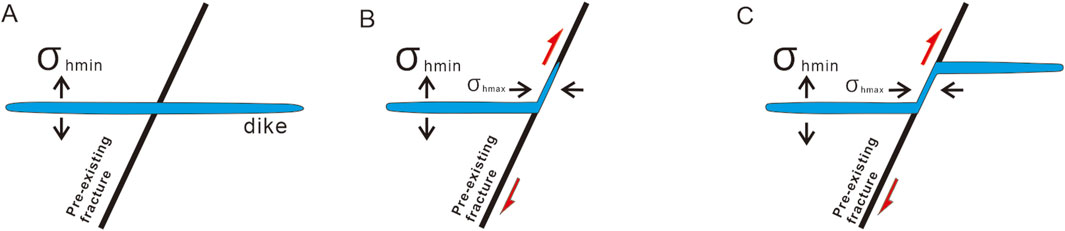
Figure 1. Interaction of hydraulic fracture and pre-existing fracture. (A) Penetration. (B) Non-penetration and intrusion along fracture. (C) Partially intrusion along fracture and penetration (modified from Lu et al., 2015).
The redistribution of stress and modification of bedrock mechanical properties, particularly in granitic rocks, can be driven by dike intrusion. Pre-existing fractures facilitate fault reactivation, while dikes act as mechanical discontinuities, concentrating fractures along their margins (Segall and Pollard, 1983; Martel et al., 1988). These interactions generate differential stress zones that drive heterogeneous deformation, including the development of faults and shear zones (Ernst et al., 2001; Ghodke et al., 2018). Fracture networks amplified by stress perturbations from dike emplacement create pathways for strain localization, thereby linking magmatic and tectonic processes (Ghodke et al., 2018; Dering et al., 2019; Yang and Kim, 2021).
The interaction between dikes and host structures determines whether deformation localizes faults or inhibits propagation (Rivalta et al., 2015; Drymoni et al., 2021). For example, dikes exploiting fractures may reactivate them as faults, whereas intact dike margins can act as barriers. Analyzing these geometric and mechanical interactions provides critical insights into paleostress conditions, magmatic-tectonic evolution, and fluid pathways. Distinguishing forceful from passive emplacement thus becomes essential for reconstructing crustal deformation histories.
We selected a series of well-exposed dikes intruded into a late Cretaceous granite in Busan, SE Korea for this study (Figure 2). The objectives of this study are: (1) describing the characteristics of dike geometry, (2) interpreting the dike emplacement mechanism, (3) analyzing fracture networks related to dike emplacement. For these purposes, in this study, we investigate the dike emplacement patterns associated with the Eocene extensional stage and the development of strike-slip faults that deform the dikes.
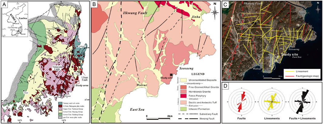
Figure 2. (A) Geological map and major faults of the Gyeongsang Basin (modified from Lee, 2000). (B) Geologic map around the study area (modified from Kee et al., 2003). (C) Satellite image and lineaments around the study area (from Google Earth; Kim et al., 2003). NNE-SSW trending lineaments are dominant. (D) Rose diagrams showing the dominant orientation of faults and lineaments (KOPEC, 2009).
2 Geological background
The study area is located in Seosaeng-myeon, Ulsan, South Korea, which is the southeastern part of the Gyeongsang Basin (Figure 2). This region comprises Cretaceous sedimentary rocks intruded by later igneous rocks, overlain by Quaternary alluvial deposits (Kim et al., 2003; Figure 2). Widely distributed sedimentary units called the Icheonri Formation in Ilgwang-myeon and Seosaeng-myeon include conglomerate, sandstone, siltstone, and mudstone (Son et al., 1978; Kim et al., 2022). The Icheonri Formation was initially classified as part of the Silla Conglomerate within the Gyeongsang Supergroup (Son et al., 1978), which was later reassigned as the Dadaepo Formation of the Yucheon Group (Kim et al., 1998). Bedding planes in the Icheonri Formation typically strike northeast, dipping gently northwest in Ilgwang-myeon and southeast in Seosaeng-myeon (Kim et al., 2003).
In Seosaeng-myeon, the landscape is predominantly composed of Late Cretaceous to Paleogene granitic rocks, with hornblende granite being the dominant type and biotite granite occurring locally near the Ilgwang mining area (Kee et al., 2003; Kim et al., 2003). The hornblende granite is intruded by both acidic and mafic dikes, with cross-cutting relationships indicating the more recent emplacement of mafic dikes.
These dikes were likely emplaced during the Eocene to Oligocene, coinciding with the rollback of the Pacific-Eurasian subduction zone and the opening of the East Sea (Son et al., 2007; 2013; Yang et al., 2008). The granite bedrock in southeast Korea, dated to 65.8–63.2 Ma (K-Ar) and 67.3–62.8 Ma (Rb-Sr), hosts dike clusters of basaltic to rhyolitic composition, which belong to the calc-alkaline magma series typically associated with subduction-related volcanic arcs (Kim et al., 2002; Son et al., 2007; Kim et al., 2011). Radiometric data point to two pulses of basaltic dike emplacement: an inland phase at ∼48 Ma (Kim et al., 2005) and a later coastal phase at ∼44 Ma (KOPEC, 2007). In contrast, intermediate and acidic dikes were intruded earlier, at 55.9 Ma and 53.0 Ma respectively, consistent with progressive magma differentiation and mixing in the plumbing system (Yang et al., 2008). These chronological data provide insights into the tectonic and magmatic evolution of southeast Korea during the Paleogene.
The Ilgwang Fault is an NNE- to NE-striking strike-slip fault that defines the western boundary of the study area and represents the easternmost structure of the Yangsan Fault System. The Ilgwang Fault is similar to the Yangsan Fault in orientation and kinematics (Kim et al., 2003; Kim et al., 2016; Ha et al., 2016; Jin et al., 2018). Depending on rock type, the width of the Ilgwang Fault deformation zone is narrower in volcanic rocks (∼200 m) and more diffuse in sedimentary rocks (∼1,000 m) due to their lower compressive strength (Jin et al., 2018).
The Yangsan Fault records dominant dextral slip under NE–SW compression during the late Paleogene (ca. 43–23 Ma), as constrained by multiple chronological approaches, including K-Ar dating of fault gouges (utilizing illite-age-analysis), U-Pb zircon dating of offset volcanic rocks, and structural relationships such as the 21.3 km dextral displacement of a 50 Ma A-type granite (Hwang et al., 2007b; Ha et al., 2016; Cheon et al., 2017a). During the Middle Miocene (ca. 16 Ma), localized sinistral reactivation occurred under NNW–SSE compression, associated with the subduction of the Philippine Sea Plate, as evidenced by structural overprinting and the displacement of Miocene basin fills (Son et al., 2015).
3 Methodology
To map the DF2 system with precision, we established a 1 m × 1 m grid across the outcrop. Detailed sketches of each grid cell documented the spatial relationships between dikes, fractures, and faults, including cross-cutting relationships and kinematic indicators (e.g., slickenlines and secondary fractures). High-resolution photomosaic images, constructed using Adobe Photoshop, provided a continuous visual base for structural mapping, enabling digitization of features across the ∼200 m × 200 m exposure area. Geometric restoration was performed to determine the local dilation direction during dike emplacement and to reconstruct the pre-intrusion host rock configuration. This procedure involved digitally removing dikes exhibiting complex geometries (e.g., zigzag patterns) and realigning key piercing points (e.g., kink bends, fracture intersections) to their original pre-displacement positions. We emphasize that this approach reconstructs the dilation direction (strain) during emplacement, which does not necessarily coincide with principal stress orientations. This method determines dike opening directions and reconstructs pre-existing fracture networks, despite inherent limitations in paleostress reconstruction from structurally controlled intrusions (Forslund and Gudmundsson, 1992; Acocella et al., 2000; Yang et al., 2008).
Topological analysis can characterize the geometry and spatial connectivity of the DF2 system. This method quantifies the connectivity of the fracture system by distinguishing invariant topological attributes (e.g., connection counts) from variable geometric properties, such as length or area (Sanderson and Nixon, 2015; Sanderson and Nixon, 2018). In 2D, fractures are modeled as traces (lines) interconnected by nodes and branches. Nodes are categorized as I-nodes (isolated fracture ends), Y-nodes (junctions splitting/merging fractures), or X-nodes (intersections of two fractures). Branches are classified as II (isolated), IC (linking isolated and junctional nodes), or CC (connecting two junctions), with ternary diagrams visualizing their proportional contributions to connectivity.
Two key metrics were analyzed: (1) 2D fracture intensity (P21), calculated as total fracture trace length per unit area (area count method; Equation 1), and (2) connections per branch (CB), a dimensionless index (0–2) where 0 represents isolated II-branches and near 2 indicates highly connected IC/CC networks (Equation 2). This approach isolates structural connectivity patterns independent of scale or deformation history, providing insights into fracture network evolution. Moreover, enhanced structural connectivity in fractured reservoirs or fault damage zones is often associated with increased effective permeability and hydraulic transmissivity. Thus, CB serves not only as a geometric descriptor but also as a useful proxy for assessing fluid flow potential within fracture systems (Sanderson and Nixon, 2018; Mendes et al., 2022). Field-derived data were digitized and refined using Adobe Photoshop/Illustrator, followed by quantitative analysis of P21 and
(∑L: sum of the fracture trace lengths, A: Area)
(NY, NX: Count of Y and X nodes, NB: Count of CC, CI, and II branches)
4 Results and interpretation
4.1 Fracture networks in dike cluster area
The widely exposed granite bedrock contains mafic dike clusters, fractures, and faults. Figure 3 illustrates a detailed structural map of these features in the studied outcrop. The fracture network shows two dominant trends: ENE-WSW (or E-W) and NNE-SSW (or N-S; Figures 3, 4). NE-SW striking fractures, exhibiting good continuity, cross-cut the two dominant fracture sets and enhance the connectivity of the grid-like network. The mafic dike cluster region, west of the main fault, exhibits a grid-like fracture network, with fracture orientations systematically varying with proximity to the fault. The main fault, which extends over 250 m, both cuts through and follows the boundaries of highly deformed NE-striking dikes, and is characterized by 5–10 cm thick gouge zones and brecciation within and along the margins of these dikes. The main fault gradually diminishes in intensity toward the north. Smaller-scale faults, trending NNE and E–W, occur within and along the margins of the dikes, with fault strikes that are parallel or sub-parallel to the dike orientation, particularly at points ofbending or branching. Hydrothermal alteration, including calcite vein formation, is widespread along extensional fractures and faults, particularly within fault zones and tip damage zones.
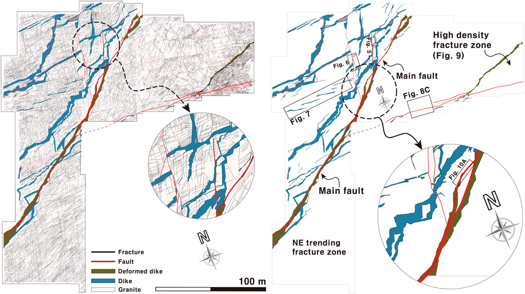
Figure 3. Structural map of the study area within the construction site, showing the distribution of fractures, faults, and dikes. The map highlights the primary trends of dikes in ENE, NNE, and NE orientations, along with their spatial relationships with fractures and fault systems. Main faults develop along the boundaries or within NE-striking dikes. Dike distribution and fracture orientation are governed by major faults. Passive intrusion creates dikes with zigzag shapes controlled by pre-existing fractures.
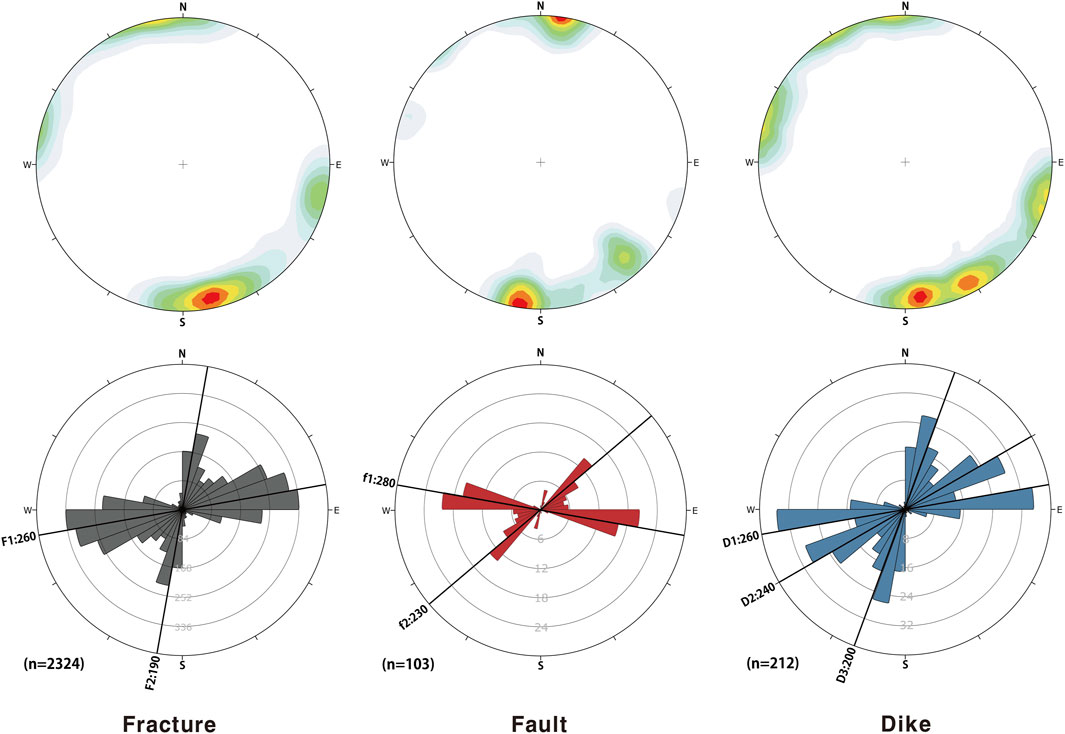
Figure 4. Equal-area stereonet and rose diagram analyses of the study area of fractures, faults, and dikes. Fractures predominantly display ENE and NNE orientations, forming a high-intensity grid-like pattern. Faults are primarily oriented WNW, NE-SW, and dikes exhibit ENE, NNE, and NE orientations.
4.2 Passive dike intrusion and apparent fault displacement
Dike trajectories are controlled by mechanical interactions between shear stresses and pre-existing fractures, with host rock heterogeneity and magmatic overpressure further influencing propagation dynamics. At dike tips, tensile fractures transition to shear fractures as magmatic pressure and host rock heterogeneity rotate principal stress orientations (Gudmundsson, 2002; Dering et al., 2019). This stress reconfiguration drives the development of en-echelon fracture arrays and promotes fault reactivation through localized strain accumulation. In the study area, three distinct dike orientations reflect these stress-fracture interactions (Figures 3, 4): ENE-striking dikes exhibit sharp, planar boundaries and extensive lateral continuity, terminating at or intruding along NNE-oriented fractures (Figure 1B) or developing trailing geometries (Figure 1C). NNE-striking dikes display limited continuity, forming sinuous (zigzag) geometries where they interact with ENE-striking dikes. NE-striking dikes maintain lateral continuity despite irregular boundaries and variable thickness, occasionally exploiting pre-existing NNE- or ENE-striking fractures as pathways.
The direction of dike extension typically aligns with the σ3 orientation. However, in regions with complex geometries caused by passive intrusion, such as dike bending, branching, or irregular terminations, this relationship becomes unclear. The three dominant dike orientations (Figure 4) indicate variable propagation paths governed by local rotations of stress field or pre-existing fracture networks, complicating the identification of the σ3 direction. To address this uncertainty, geometric restoration methods were applied to resolve complex stress fields and reconstruct stress regimes associated with non-linear fracture patterns.
In this study, dike boundaries were geometrically restored, and their relationships with fractures were analyzed (Figure 5). Dikes were first extracted from the bedrock (Figure 5A), with kink points along dike boundaries identified as piercing points for restoration (Figure 5B). The shortest path connecting these points revealed a dilation direction of approximately 332° (σHmin: 332°, σHmax: 062°; Figures 5C,D). Although the shortest-path reconstruction indicated a consistent dilation direction of approximately 332°, slight mismatches along dike boundaries remained. To resolve these mismatches, the northernmost fracture was adjusted by a 3° counterclockwise rotation, which aligned the fractures into a pre-intrusion configuration. This adjustment suggests that the mismatches resulted from oblique dike intrusion or irregular fracture growth along dike margins. Additionally, restricted fracture propagation at dike tips could induce localized stress variations, leading to block rotation within the dike body. The main dike (deformed dike) extends over 250 m with irregular boundaries and complex branching, yet maintains overall lateral continuity representing the primary extensional direction (Figure 3). We interpret this 332° dilation as reflecting the local minimum principal stress (σ3) orientation during emplacement, indicating NW–SE extension and σHmax of ∼062°. However, dilation represents strain and does not necessarily coincide with stress orientation. This interpretation pertains to the dominant NE-trending extensional system, whereas dikes that intruded passively along pre-existing ENE and NNE fractures reflect structural inheritance rather than the prevailing ambient stress conditions.
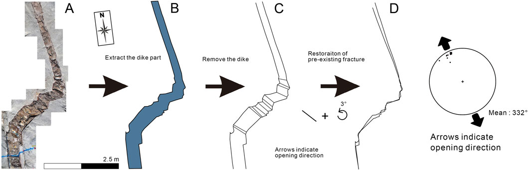
Figure 5. (A) Detailed grid map of a mafic dike. (B–D) Restoration of the zigzag bending type dike. Stereographic projection indicates trends of opening direction of the mafic dike (332°).
In the study area, dikes are observed intruding into orthogonal fracture networks, with representative examples in Figure 6. Irregular NE- and ENE-striking dikes exhibit blunt-ended tips and fault-controlled geometries, indicating passive intrusion where magma follows pre-existing fractures and is deflected by structural barriers (Figure 6A). Some thin dikes (centimeter-scale) with narrowing tips form independently and terminate at N-S-striking faults. The dike geometry, including offsets and thickness variations, implies structurally controlled emplacement. The N-S-striking faults create apparent left-lateral displacement along the western fault segment and apparent right-lateral displacement along the eastern fault. This displacement is termed “apparent” because it results not from post-emplacement fault slip but from the inability of intruding magma to propagate across the pre-existing discontinuity. Instead, magma was deflected along the fault plane, creating discontinuous dike segments that appear offset in map view. The asymmetric thickness and distribution variations across the fault confirm syn-emplacement structural control rather than post-intrusion faulting.
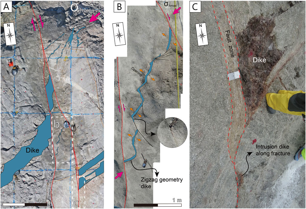
Figure 6. (A) Mafic dikes associated with shear stress between two dextral faults. (B) Dike with zig-zag geometry. The dikes are extended in the direction of minimum horizontal principal stress. (C) Fracture-controlled dike. The dike exhibits passive intrusion characteristics, non-penetration pre-existing fractures and injecting along them.
A dike approximately 5 cm wide confined between two faults displays a zigzag geometry (Figure 6B). The thickness of these zigzag-patterned dikes varies with fracture orientation, and some partially intrude N-S-striking fractures (Figure 6B). These features indicate passive dike emplacement guided by pre-existing fractures. Irregular dike propagation along fractures results in displacement mismatches, causing terminations or deflections at fracture orientation changes (Figures 3, 6B). Dikes terminate at the fractures, with some partially intruding along these fractures rather than being fully offset (Figure 6C). The NE σHmax (062°) imposed dextral shear along the fractures and controlled NE-striking dike alignment, consistent with a stable stress regime during emplacement.
En-echelon E-W-striking dikes formed as overlapping or stepping sub-parallel fractures under an E-W σHmax, commonly observed in extensional and transtensional settings (Figures 3, 7). In fault growth models, such fractures develop in bedrock during early fault evolution or as a response to distributed shear strain (Mollema and Antonellini, 1999; Peacock, 2001). The mapped en-echelon dikes extend to approximately 6 m, with width of 0.3 to 0.7 m and spacing of 2.4–3.1 m. Their widths are greatest at the midsection and gradually taper toward the edges.
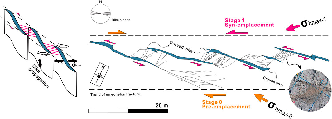
Figure 7. En-echelon pattern of mafic dikes. Stage 0: En-echelon fractures form under E-W maximum horizontal stress. Stage 1: Mafic dikes intrude along pre-existing en-echelon fractures under NE-SW maximum horizontal stress.
The E-W-striking en-echelon fractures could originate as extensional features under an E-W σHmax stress which may also explain their association with right-lateral shear deformation (Figure 7). During dike emplacement, the regional stress regime shifted from an earlier E-W to NE σHmax (Figure 5), indicating a significant reorientation of the principal stress axis. This shift is supported by sigmoidal (curved) dikes within shear zones, which resemble tension gashes and indicate NE σHmax (Figure 7). Additionally, NE-striking veins and fractures are confined between dikes, without extending beyond their boundaries. The geometry of connecting fractures suggests sinistral shear displacement. NE-striking fractures between dikes contain vein infill, indicating post-emplacement hydrothermal activity.
Significantly, subsidiary veins confined between E-W dikes exhibit geometric characteristics identical to linking damage zones observed in reactivated E-W sinistral fault systems elsewhere in the study area. This indicates a three-stage evolution: first, E-W σHmax generated initial en-echelon fractures, second, NE σHmax controlled dike intrusion along these fractures, producing curved geometries at terminations under normal fault conditions; and third, continued NE σHmax led to post-emplacement sinistral deformation under strike-slip fault conditions, creating linking damage zone characteristics between dike segments.
4.3 Vein formation after dike emplacement
Calcite-dominated veins preferentially filled pre-existing fractures aligned with dike orientations and clustered along dike margins and interiors, where hydrothermal fluids intensely altered the dike (Figures 8A,B). Vein formation occurred after dike cooling, as indicated by cross-cutting relationships. Late-stage hydrothermal activity produced a stockwork vein network and brecciated dike interiors through selective dissolution of mechanically weakened zones (Figure 8B).
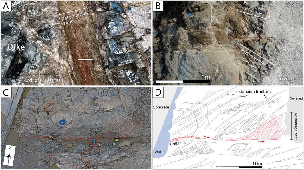
Figure 8. (A) Calcite veins sealed around deformation zone. Orientation is non-systematic. (B) Deformed margin of mafic dike and veins sealed inside deformation zone. Weathered and deformed mafic dike seem to be coble and gravel. (C,D) Sinistral faults related structures. Along the fault, highly altered zone and tip damage zone are recognized.
Stress concentrations at dike-bedrock interfaces (driven by stiffness contrasts and mechanical anisotropy) localized fracture propagation and vein mineralization (d’Alessio and Martel, 2005; Gwon and Kim, 2016). ENE-striking sinistral faults and associated NE-SW secondary fractures also contain veins (Figures 8C,D), indicating that fault reactivation occurred after dike emplacement.
4.4 ENE-striking fault reactivation
The fracture system in the study area is dominated by two principal orientations. Several ENE-striking fractures are reactivated as sinistral faults under NE horizontal stress (Figures 3, 8C, 9). One of the sinistral faults in the study area is associated with an 8 m-wide tip damage zone containing densely clustered secondary fractures (averaging 10 m in length) that trend 045° with steep dips (Figure 8D).
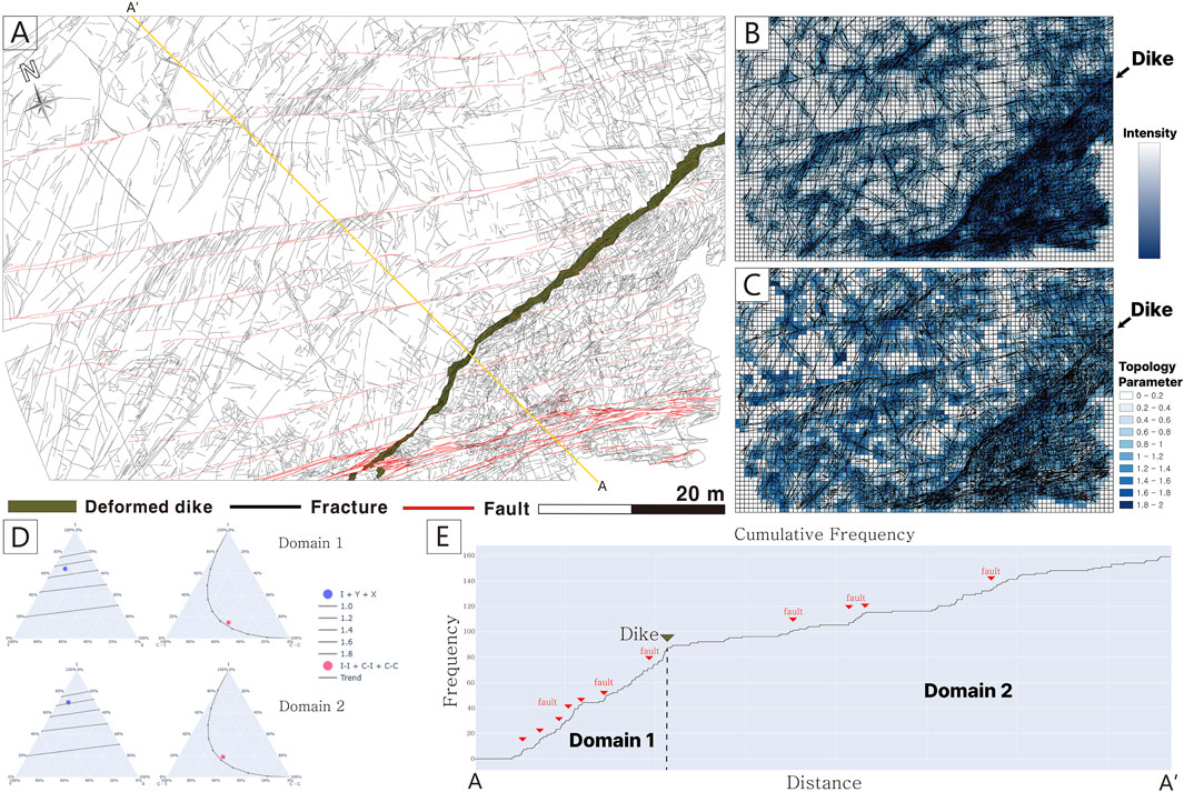
Figure 9. Fracture intensity and connectivity analysis across the DF2 network. (A) Detailed structural mapping of fractures, faults, and dikes in the study area, showing increased fracture intensity in fault linkage zones and domain 1. (B) Spatial visualization of fracture intensity (P21) highlighting localized variations influenced by the dike boundary. (C) Connectivity map (
Detailed mapping on an excavation surface (Figure 9A) reveals ENE-striking sinistral faults with left-stepping geometries and vein-filled linking damage zones. Secondary fractures concentrate along fault segments and within linkage zones, where fracture density peaks. In the southeastern part of Figure 9A, a sinistral fault (thick red lines) crosscuts a dike, forming breccia and branching into multiple segments. Fracture density analysis indicates higher values east of the NE-striking dike (Domain 1) compared to the west (Domain 2; Figure 9A).
4.5 Dike-controlled fracture system and topological analysis
To investigate the structural interactions of DF2 system, we employed a topological analysis in the SE sector of the study area (Figures 3, 9). Digitized fracture traces were analyzed using QGIS’s NetworkGT toolkit to calculate two metrics (P21 and
4.5.1 Fracture intensity and connections per branch
Domain 1 (6.14 m−1) exhibits 2.84 times higher P21 than Domain 2 (2.16 m−1), with a domain area ratio of 1:4.34 (656.98 m2:2850.02 m2; Table 1 and Figure 9B). This sharp contrast in fracture intensity aligns with the dike boundary. Domain 1 displays uniformly high fracture intensity, whereas Domain 2 shows fractures concentrated near fault linkage zones and fault-tensile fracture intersection zones (Figure 9B). This partitioning reflects the dike-dominant control on fracturing in Domain 1 and fault-driven processes in Domain 2.
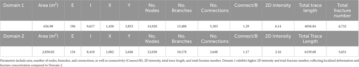
Table 1. Quantitative analysis of fracture network characteristics in Domain 1 and Domain 2.
4.5.2 Dike as a mechanical barrier
Fractures intersecting the A-A′ transect were identified and counted to construct a cumulative frequency graph (Figure 9E). The results indicate that fracture frequency varies with proximity to the dike, with the dike exerting a stronger control on fracture patterns than the surrounding faults. The study area comprises mafic dikes intruding a granite basement, later crosscut by E-W-striking sinistral strike-slip faults. These faults create lateral damage zones with high fracture densities; however, the dikes act as mechanical barriers, restricting fracture propagation and growth (Segall and Pollard, 1980; Ruf et al., 1998; Bai and Pollard, 2000; Shang et al., 2018). This barrier effect arises from mechanical contrasts, including differences in stiffness and tensile strength between the dikes and the granite. These contrasts modify local stress fields, confine lateral fracture propagation, and influence the deformation dynamics of the surrounding rock mass. Stress and strain concentrate near these mechanical discontinuities, leading to localized deformation along dike margins.
5 Discussion
5.1 Dike-fault geometry and fault reactivation
During dike intrusion, magma-driven stresses (e.g., overpressure and shear coupling along fractures) reorient the local stress field. These stress perturbations can trigger slip along pre-existing fractures or generate new tensile fractures parallel to the NE σHmax (062° ± 10°), which dominated during the main phase of dike emplacement (Figures 3, 10A). These fractures and associated normal faults act as preferential magma pathways, contributing to fault system maturation through cyclical damage accumulation (Muirhead et al., 2016; Currenti et al., 2019). In our study area, these fractures and associated normal faults subsequently served as preferential pathways for magma migration, promoting cyclical damage accumulation and the progressive maturation of the fault zones. This process is evidenced by sigmoidal dike geometries and overprinting slickenlines (Figures 7, 10E,F). Repeated intrusions convert fault zones into complex networks, generating secondary fractures, subsidiary faults, and branching geometries. Mature fault systems accommodate dikes with complex geometries, contrasting with simpler geometries in undeformed bedrock (Spacapan et al., 2016).
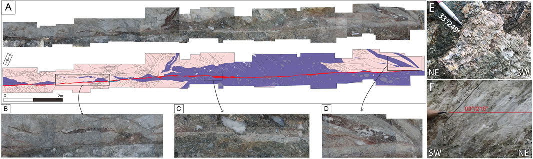
Figure 10. (A) Observed segment of a NE-striking fault within the dike. (B) Dikes intruded along pre-existing fractures or simultaneous tensile fractures. (C) Thick fault gouge developed within the dike, and faults cutting through both dikes and veins. (D) A tip of dike controlled by the NE-striking fracture. (E) Oblique calcite slickenfiber (33°/249°). (F) Superimposed slickenlines on the NE-striking fault plane showing oblique-slip (46°/213°) and strike-slip (03°/215°) senses.
The NE-striking dikes form laterally continuous networks (>250 m) displaying asymmetric and fault-parallel branching geometries (Figures 3, 10). Dense fracturing occurs within dike interiors and along margins that run parallel to adjacent faults, merging into ∼8–10 m wide deformation zones surrounding those faults. These zones contrast sharply with narrow fault gouge zones (∼5 cm) along slip surfaces. Faults develop along dike boundaries and interiors, displacing dike margins and internal veins (Figures 3, 10A,C). Blunt-ended dike tips and their injection into fractures aligned with main faults (Figures 10B,D) indicate that emplacement was controlled by pre-existing or simultaneous tensile fractures. Slickenlines record normal-oblique slip (plunge 33°, 46°) and strike-slip (plunge 1°) movements (Figures 10E,F). Superimposed slickenlines indicate post-intrusion clockwise stress rotation (Δ σHmax = ∼20°) and multi-phase reactivation under normal to dextral fault movement (Gwon and Kim, 2016).
The NE-striking main fault dips northwest and accommodates a dike cluster in its hanging wall, while fracture patterns differ between the hanging wall and footwall (Figure 3). This suggests the main fault may act as the boundary of a local graben during dike emplacement (Rahimi et al., 2025). Geometric similarity between dikes and main faults, including branching patterns and repeated fault reactivations along dikes, indicates that pre-existing normal faults provided pathways for dike emplacement. Fault nucleation within dike interiors and shear-coupled reactivations further support this process.
Dikes initially used tensile fractures (Mode I) under a NE-striking σHmax, as shown by fracture arrays parallel to the dike. Subsequent fault movements, transitioning from normal to strike-slip, as recorded by striae overprinting (Figures 10E,F), reflect a clockwise rotation of the post-emplacement stress field from a normal to a strike-slip regime. Repeated reactivation along dike interiors and boundaries demonstrates their role as inherent structural weaknesses, facilitating strain localization during tectonic events.
These observations demonstrate that dike-fault interactions are governed by syn-emplacement stage coupling of magma-driven fracturing and tectonic shear, rather than separate tectonic episodes.
5.2 Dike emplacement mechanisms: forceful vs. passive intrusion
Forceful intrusions generate new fractures by exceeding the tensile strength of intact rock, whereas passive intrusions utilize pre-existing fractures under moderate magmatic pressure. These mechanisms often coexist, reflecting the interplay between magmatic pressure and structural fracture complexity of the bedrock (Pollard, 1987; Lister and Kerr, 1991; Martínez-Poza et al., 2014). The emplacement of dikes in the study area occurs through two primary emplacement mechanisms.
The ENE- and ENE-striking fractures form a grid-like pattern with dikes intruding along fractures (Figures 1B, 3, 6C) or partially penetrating them (Figures 1C, 3, 6A). Zigzag geometries indicative of passive intrusion are observed at various scales (Figures 3, 5, 6B). Restoration of these geometries suggests a σHmax orientation of 062° aligned with forceful dike planes (Figures 3, 6A, 10B). Dike intrusions associated with shear deformation form en-echelon structures (Figure 7) and reactivate N-S-striking fractures (Figure 6). NE-striking dikes follow primary extension, generating fault parallel or sub-parallel fractures during forceful emplacement. Post-dike emplacement faulting involved hydrofracturing (Figure 9).
A hybrid model integrating passive and forceful intrusion mechanisms is proposed based on our observations (Figure 11). Throughout the syn-emplacement stage, dikes employ a dual mechanism: exploiting pre-existing fractures in the basement rock and propagating through intact bedrock via magmatic overpressure. Post-emplacement ENE-striking sinistral movement occurs under a rotated stress field where the NE σHmax becomes dominant (Figures 7, 8C, 9A). This motion is facilitated by inversion of the σ1 and σ2 axes during dike emplacement, which also triggers hydrothermal alteration along reactivated fault zones. Stress orientations inferred here assume regional homogeneity, but local variations could arise from complex magma chamber geometries (e.g., multi-chamber systems; Hazarika et al., 2024). As our study area lacks exposed chambers, this remains speculative. Future work should integrate geophysical constraints to resolve such uncertainties.
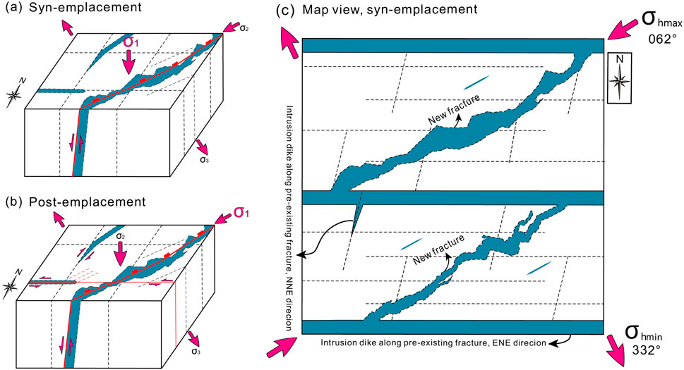
Figure 11. Conceptual model illustrating dike intrusion and associated fracture development under regional stress conditions. (A) During syn-emplacement, NNE- and ENE-striking dikes intrude along pre-existing fractures, guided by the maximum horizontal compressive stress (σHmax; 062°) and minimum horizontal compressive stress with NE-striking dikes (σHmin; 332°). (B) Post-emplacement, subsequent tensile-shear transition generated ENE sinistral faults and hydrothermal mineral infilling. (C) Map view, syn-emplacement, forceful intrusion induces new fracture formation at dike tips and margins, while passive intrusion follows pre-existing fracture networks.
Hybrid emplacement appears broadly applicable, depending on three interdependent controls. (1) Depth–rheology: At shallow levels (<∼5 km) low mean stress promotes forceful, mode-I dike (Brace and Kohlstedt, 1980; Rybacki et al., 2021). Within the brittle–ductile transition (5–15 km) both tensile failure and structural reactivation coexist, yielding true hybrids (this study). Below ∼15 km, high-temperature ductile flow confines magma to pre-existing anisotropies (Klepeis et al., 2022; Chatterjee et al., 2024). (2) Host lithology: sedimentary successions generate sill-dike networks along bedding (Spacapan et al., 2016; Magee et al., 2016), whereas high-grade gneiss directs magma along foliations (He et al., 2020; Zhang et al., 2024). (3) Magma rheology: low viscosities (∼102–104 Pa s) favour pervasive fracture infiltration, intermediate values (∼104–106 Pa s) optimize hybrid behavior, and high viscosities (>∼106 Pa s) bias intrusion toward fault-controlled pathways (Giordano et al., 2008).
These results from the study area demonstrate that dike emplacement systems result from the coupled effects of structural inheritance and magmatic forcing. Pre-existing fractures facilitate passive magma intrusion, while magma overpressure generates new fractures via forceful intrusion. This dual mechanism, where structural inheritance and structural generation operate throughout the syn-emplacement stage, highlights the need for integrated models to resolve crustal deformation in pre-existing basement rocks.
6 Conclusion
This study elucidates the dynamic interplay between dike emplacement, fracture networks, and fault reactivation of DF2 system in Late Cretaceous granitic bedrock of southeast Korea. By integrating field observations, geometric restoration, and topological analysis, we demonstrate that dike intrusions occur through hybrid mechanisms combining forceful fracturing of intact bedrock and passive exploitation of pre-existing fractures, governed by syn-emplacement stage coupling of magmatic and tectonic processes. Key findings include:
1. Hybrid Emplacement Mechanisms: NE-striking dikes exhibit both forceful (Mode I fracturing under NW-SE σ3) and passive (guided by ENE-WSW/NNE-SSW fracture sets) intrusion styles. Their coexistence reflects interactions between magmatic overpressure and structural inheritance, with dike geometries (e.g., zigzag patterns, blunt tips) serving as characteristic markers of these processes.
2. Dike-Fault Mechanical Interactions: Dikes act as dual mechanical features, serving as both barriers that inhibit fracture propagation and stress concentrators that promote fault reactivation. Fracture intensity (P21) and connectivity (
3. Structural Inheritance in DF2 system: Pre-existing fractures and faults control dike trajectories, guiding magma along zones of mechanical weakness. As dikes intrude, they generate localized stress variations that promote fault re-activation, nucleation, and strain concentration along their margins and interiors. This interaction results in structurally interconnected dike-fault networks, where repeated reactivation reinforces these zones as long-term crustal weaknesses.
Data availability statement
The original contributions presented in the study are included in the article; further inquiries can be directed to the corresponding author.
Author contributions
JL: Formal Analysis, Visualization, Methodology, Data curation, Resources, Investigation, Software, Writing – review and editing, Conceptualization, Writing – original draft. GK: Formal Analysis, Visualization, Methodology, Software, Writing – original draft. Y-SK: Supervision, Writing – review and editing, Funding acquisition.
Funding
The author(s) declare that financial support was received for the research and/or publication of this article. This research was supported by Global-Learning and Academic research institution for Master’s PhD students, and Postdocs (LAMP) Program of the National Research Foundation of Korea (NRF) grant funded by the Ministry of Education (No. RS-2023-00301702) and the Human Resources Development Project for HLW Management hosted by KORAD and MOTIE.
Conflict of interest
The authors declare that the research was conducted in the absence of any commercial or financial relationships that could be construed as a potential conflict of interest.
Generative AI statement
The author(s) declare that Generative AI was used in the creation of this manuscript. After writing the manuscript, we used generative AI to correct grammatical errors.
Any alternative text (alt text) provided alongside figures in this article has been generated by Frontiers with the support of artificial intelligence and reasonable efforts have been made to ensure accuracy, including review by the authors wherever possible. If you identify any issues, please contact us.
Publisher’s note
All claims expressed in this article are solely those of the authors and do not necessarily represent those of their affiliated organizations, or those of the publisher, the editors and the reviewers. Any product that may be evaluated in this article, or claim that may be made by its manufacturer, is not guaranteed or endorsed by the publisher.
References
Acocella, V., Gudmundsson, A., and Funiciello, R. (2000). Interaction and linkage of extension fractures and normal faults: examples from the rift zone of Iceland. J. Struct. Geol. 22, 1233–1246. doi:10.1016/S0191-8141(00)00031-6
Bai, T., Pollard, D. D., and Gross, M. R. (2000). Mechanical prediction of fracture aperture in layered rocks. J. Geophys. Res. Solid Earth. 105, 707–721. doi:10.1029/1999JB900303
Bistacchi, A., Tibaldi, A., Pasquarè, F. A., and Rust, D. (2012). The association of cone–sheets and radial dykes: data from the Isle of Skye (UK), numerical modelling, and implications for shallow magma chambers. Earth Planet. Sci. Lett. 339, 46–56. doi:10.1016/j.epsl.2012.05.020
Brace, W. F., and Kohlstedt, D. L. (1980). Limits on lithospheric stress imposed by laboratory experiments. J. Geophys. Res. Solid Earth 85 (B11), 6248–6252. doi:10.1029/JB085iB11p06248
Browning, J., Karaoğlu, Ö., Bayer, Ö., Turgay, M. B., and Acocella, V. (2021). Stress fields around magma chambers influenced by elastic thermo-mechanical deformation: implications for forecasting chamber failure. Bull. Volcanol. 83, 48. doi:10.1007/s00445-021-01471-2
Buck, W. R., Einarsson, P., and Brandsdóttir, B. (2006). Tectonic stress and magma chamber size as controls on dike propagation: constraints from the 1975–1984 Krafla rifting episode. J. Geophys. Res. Solid Earth. 111, B12404. doi:10.1029/2005JB003879
Chatterjee, A., Daczko, N. R., Dey, J., and Piazolo, S. (2024). Hydrous shear zones are sites of melt transfer in the lower arc crust: a case study from Fiordland, New Zealand. J. Metamorph. Geol. 42 (7), 933–956. doi:10.1111/jmg.12788
Cheon, Y., Ha, S., Lee, S., Cho, H., and Son, M. (2017a). Deformation features and history of the Yangsan fault zone in the Eonyang-Gyeongju area, SE Korea. J. Geol. Soc. Korea 53, 95–114. doi:10.14770/jgsk.2017.53.1.95
Currenti, G., and Bonaccorso, A. (2019). Cyclic magma recharge pulses detected by high-precision strainmeter data: the case of 2017 inter-eruptive activity at Etna volcano. Sci. Rep. 9, 7553. doi:10.1038/s41598-019-44066-w
d'Alessio, M., and Martel, S. J. (2005). Development of strike-slip faults from dikes, Sequoia National Park, California. J. Struct. Geol. 27, 35–49. doi:10.1016/j.jsg.2004.06.013
Dahm, T. (2000). On the shape and velocity of fluid-filled fractures in the Earth. Geophys. J. Int. 142, 181–192. doi:10.1046/j.1365-246x.2000.00148.x
Delaney, P. T., and Pollard, D. D. (1982). Solidification of basaltic magma during flow in a dike. Am. J. Sci. 282, 856–885. doi:10.2475/ajs.282.6.856
Delaney, P. T., Pollard, D. D., Ziony, J. I., and McKee, E. H. (1986). Field relations between dikes and joints: emplacement processes and paleostress analysis. J. Geophys. Res. Solid Earth. 91, 4920–4938. doi:10.1029/JB091iB05p04920
Dering, G. M., Micklethwaite, S., Cruden, A. R., Barnes, S. J., and Fiorentini, M. L. (2019). Evidence for dyke-parallel shear during syn-intrusion fracturing. Earth Planet. Sci. Lett. 507, 119–130. doi:10.1016/j.epsl.2018.10.024
Drymoni, K., Browning, J., and Gudmundsson, A. (2021). Volcanotectonic interactions between inclined sheets, dykes, and faults at the Santorini Volcano, Greece. J. Volcanol. Geotherm. Res. 416, 107294. doi:10.1016/j.jvolgeores.2021.107294
Edwards, P., Choi, J.-H., and Kim, Y.-S. (2017). Variations in thickness of fault-controlled dikes and its implications: a case study of Gosung area, South-East Korea. Isl. Arc 26, e12181. doi:10.1111/iar.12181
Ernst, R., Grosfils, E., and Mege, D. (2001). Giant dike swarms: earth, venus, and mars. Annu. Rev. Earth Planet. Sci. 29, 489–534. doi:10.1146/annurev.earth.29.1.489
Forslund, T., and Gudmundsson, A. (1992). Structure of tertiary and Pleistocene normal faults in Iceland. Tectonics 11, 57–68. doi:10.1029/91TC01536
Ghodke, S. S., Rathna, K., Kokandakar, G. J., Nagaraju, B., More, L. B., Bhosle, M. V., et al. (2018). Emplacement and growth of alkaline dikes: insights from the shonkinite dikes (Elchuru alkaline complex, SE India). J. Struct. Geol. 117, 219–236. doi:10.1016/j.jsg.2018.09.016
Giordano, D., Russell, J. K., and Dingwell, D. B. (2008). Viscosity of magmatic liquids: a model. Earth Planet. Sci. Lett. 271 (1), 123–134. doi:10.1016/j.epsl.2008.03.038
Gudmundsson, A. (2002). Emplacement and arrest of sheets and dykes in central volcanoes. J. Volcanol. Geotherm. Res. 116, 279–298. doi:10.1016/S0377-0273(02)00226-3
Gudmundsson, A. (2003). Surface stresses associated with arrested dykes in rift zones. Bull. Volcanol. 65, 606–619. doi:10.1007/s00445-003-0289-7
Gudmundsson, A. (2006). How local stresses control magma-chamber ruptures, dyke injections, and eruptions in composite volcanoes. Earth-Sci. Rev. 79, 1–31. doi:10.1016/j.earscirev.2006.06.006
Gudmundsson, A. (2020). “Magma movement through the crust: dike paths,” in Volcanotectonics: understanding the structure, deformation and dynamics of volcanoes. Editor A. Gudmundsson (Cambridge: Cambridge University Press), 325–378. doi:10.1017/9781139176217.008
Gwon, S., and Kim, Y.-S. (2016). Interpretation of deformation history and paleostress based on fracture analysis exposed in a trench. J. Eng. Geol. 26, 33–49. doi:10.9720/kseg.2016.1.33
Ha, S., Cheon, Y., Kang, H.-C., Kim, J.-S., Lee, S.-K., and Son, M. (2016). Geometry and kinematics of the subsidiary faults of the Ilgwang fault, SE Korea. J. Geol. Soc. Korea 52, 31–50. doi:10.14770/jgsk.2016.52.1.31
Harlov, D. E., and Austrheim, H. (2013). “Metasomatism and the chemical transformation of rock: rock-mineral-fluid interaction in terrestrial and extraterrestrial environments,” in Metasomatism and the chemical transformation of rock. Lecture notes in Earth system sciences (Berlin, Heidelberg: Springer). doi:10.1007/978-3-642-28394-9_1
Hazarika, P. J., Dasgupta, R., Baruah, A., and Mandal, N. (2024). Ground surface displacements and stress localization driven by dual magma chamber dynamics: analytical and numerical model estimates. Int. J. Earth Sci. 113 (6), 1475–1494. doi:10.1007/s00531-024-02446-2
He, X., Tan, S., Zhou, J., Liu, Z., Zhao, Z., Yang, S., et al. (2020). Identifying the leucogranites in the Ailaoshan-Red River shear zone: constraints on the timing of the southeastward expansion of the Tibetan Plateau. Geosci. Front. 11 (3), 765–781. doi:10.1016/j.gsf.2019.07.008
Hwang, B. H., McWilliams, M., Son, M., and Yang, K. (2007b). Tectonic implication of A-type granites across the Yangsan fault, Gigye and Gyeongju areas, southeast Korean Peninsula. Int. Geol. Rev. 49, 1094–1102. doi:10.2747/0020-6814.49.12.1094
Jin, K., Kim, Y.-S., Yang, S.-J., Choi, J.-H., and Kim, K.-O. (2018). Deformation history and characteristics of the Ilgwang Fault in Southeast Korea. Geosci. J. 22, 209–226. doi:10.1007/s12303-017-0037-1
Kee, W.-S., Koh, H. J., Cho, D.-L., Kihm, Y. H., Lee, B.-J., Kim, B.-C., et al. (2003). Study on expansion of earthquake observation network and geological survey around nuclear power Plant (geology). Technical report. Daejeon, Korea: Korea Institute of Geosciences and Mineral Resources, 50.
KEPCO Engineering and Construction. (2007). Report on the fault analysis in SHINKORI NUCLEAR POWER PLANT UNITS 1 and 2.
KEPCO Engineering and Construction. (2009). Comprehensive report on a foundation of the ground in SHINKORI NUCLEAR POWER PLANT UNITS 3 and 4.
Kim, D., Hwang, J., Park, K., and Song, K. (1998). Geologic map of Pusan, Korea (1:250,000). Daejeon, Korea: Korea institute of geology, mining and materials, 62.
Kim, J.-S., Kim, J. S., and Son, M. (2002). Geochemical study of dyke swarms, SE Korea. J. Pet. Soc. Korea. 11, 182–199. Available online at: https://koreascience.kr/article/JAKO200211921975988.pdf.
Kim, J.-S., Ree, J.-H., Han, S.-H., Kim, H.-S., Lee, Y.-J., Lee, K.-J., et al. (2003). The Ilkwang fault in southeastern Korea revealed by geophysical and trench surveys. J. Geol. Soc. Korea 39 (2), 211–223. Available online at: https://www.dbpia.co.kr/pdf/pdfView.do?nodeId=NODE01594473.
Kim, J.-S., Son, M., Kim, J.-S., and Kim, S. (2005). 40Ar/39Ar ages of the tertiary dike swarm and volcanic rocks, SE Korea. J. Pet. Soc. Korea 14, 93–107. Available online at: https://koreascience.kr/article/JAKO200504703993934.pdf.
Kim, C.-M., Kim, J.-S., Song, C.-W., Son, M., and Choi, S.-J. (2011). Dyke swarms and fracture system and their relative chronology and tectonic implications in the Jukbyeon-Bugu area, Uljin, East Korea. J. Pet. Soc. Korea 20, 173–189. doi:10.7854/jpsk.2011.20.4.173
Kim, H.-J., Baek, Y. S., Jou, H.-T., Lee, S. H., Moon, S., Kim, J. S., et al. (2016). Seismic reflection imaging of quaternary faulting offshore the southeastern Korean Peninsula. Geosci. J. 20, 311–319. doi:10.1007/s12303-015-0055-9
Kim, H. J., Paik, I. S., Park, J. G., Jeong, E. K., Kim, K., Baek, S. G., et al. (2022). Cretaceous Icheonri formation at Sinpyeongri Coast, Gijang County, Busan, Korea: occurrences and values in geological heritage. J. Geol. Soc. Korea. 58, 1–22. doi:10.14770/jgsk.2022.58.1.1
Klepeis, K. A., Schwartz, J. J., Miranda, E., Lindquist, P., Jongens, R., Turnbull, R., et al. (2022). The initiation and growth of transpressional shear zones through Continental Arc lithosphere, Southwest New Zealand. Tectonics 41 (9), e2021TC007097. doi:10.1029/2021TC007097
Kubo Hutchison, A., Karlstrom, L., and Mittal, T. (2023). Multiscale spatial patterns in giant dike swarms identified through objective feature extraction. Geochem. Geophys. Geosyst. 24, e2022GC010842. doi:10.1029/2022GC010842
Lan, H., Zhang, Y., Macciotta, R., Li, L., Wu, Y., Bao, H., et al. (2022). The role of discontinuities in the susceptibility, development, and runout of rock avalanches: a review. Landslides 19, 1391–1404. doi:10.1007/s10346-022-01868-w
Le Corvec, N., Menand, T., and Lindsay, J. (2013). Interaction of ascending magma with pre-existing crustal fractures in monogenetic basaltic volcanism: an experimental approach. J. Geophys. Res. Solid Earth. 118, 968–984. doi:10.1002/jgrb.50142
Lee, J. I. (2000). Provenance and thermal maturity of the lower Cretaceous Gyeonsang Supergroup, Korea. Seoul: Seoul National University, 129.
Lister, J. R., and Kerr, R. C. (1991). Fluid-mechanical models of crack propagation and their application to magma transport in dykes. J. Geophys. Res. Solid Earth. 96, 10049–10077. doi:10.1029/91JB00600
Lu, C., Li, M., Guo, J.-C., Tang, X.-H., Zhu, H.-Y., Yong-Hui, W., et al. (2015). Engineering geological characteristics and the hydraulic fracture propagation mechanism of the sand-shale interbedded formation in the Xu5 reservoir. J. Geophys. Eng. 12, 321–339. doi:10.1088/1742-2132/12/3/321
Magee, C., Muirhead, J. D., Karvelas, A., Holford, S. P., Jackson, C. A. L., Bastow, I. D., et al. (2016). Lateral magma flow in mafic sill complexes. Geosphere 12 (3), 809–841. doi:10.1130/GES01256.1
Martel, S. J., Pollard, D. D., and Segall, P. (1988). Development of simple strike-slip fault zones, Mount Abbot quadrangle, Sierra Nevada, California. Mt. Abbot Quadrang. Sierra Nev. Calif. GSA Bull. 100, 1451–1465. doi:10.1130/0016-7606(1988)100<1451:dosssf>2.3.co;2
Martí, J., López, C., Bartolini, S., Becerril, L., and Geyer, A. (2016). Stress controls of monogenetic volcanism: a review. Front. Earth Sci. 4, 106. doi:10.3389/feart.2016.00106
Martínez-Poza, A. I., Druguet, E., Castaño, L. M., and Carreras, J. (2014). Dyke intrusion into a pre-existing joint network: the Aiguablava lamprophyre dyke swarm (Catalan Coastal Ranges). Tectonophysics 630, 75–90. doi:10.1016/j.tecto.2014.05.015
Mazzarini, F., and Musumeci, G. (2008). Hydrofracturing-related sill and dyke emplacement at shallow crustal levels: the Eastern Elba Dyke Complex, Italy. Geol. Soc. Lond. Spec. Publ. 302, 121–129. doi:10.1144/SP302.9
Mendes, L. D. C., Correia, U. M., Cunha, O. R., Oliveira, F. M., and Vidal, A. C. (2022). Topological analysis of fault network in naturally fractured reservoirs: a case study from the pre-salt section of the Santos Basin, Brazil. J. Struct. Geol. 159, 104597. doi:10.1016/j.jsg.2022.104597
Mollema, P. N., and Antonellini, M. (1999). Development of strike-slip faults in the dolomites of the Sella Group, Northern Italy. J. Struct. Geol. 21, 273–292. doi:10.1016/S0191-8141(98)00121-7
Muirhead, J. D., Kattenhorn, S. A., Lee, H., Mana, S., Turrin, B. D., Fischer, T. P., et al. (2016). Evolution of upper crustal faulting assisted by magmatic volatile release during early-stage continental rift development in the East African Rift. Geosphere 12, 1670–1700. doi:10.1130/GES01375.1
Nelson, E. J., Chipperfield, S. T., Hillis, R. R., Gilbert, J., McGowen, J., and Mildren, S. D. (2007). The relationship between closure pressures from fluid injection tests and the minimum principal stress in strong rocks. Int. J. Rock Mech. Min. Sci. 44, 787–801. doi:10.1016/j.ijrmms.2006.10.004
Nyberg, B., Nixon, C. W., and Sanderson, D. J. (2018). NetworkGT: a GIS tool for geometric and topological analysis of two-dimensional fracture networks. Geosphere 14, 1618–1634. doi:10.1130/GES01595.1
Pallister, J. S., McCausland, W. A., Jónsson, S., Lu, Z., Zahran, H. M., Hadidy, S. E., et al. (2010). Broad accommodation of rift-related extension recorded by dyke intrusion in Saudi Arabia. Nat. Geosci. 3, 705–712. doi:10.1038/ngeo966
Peacock, D. C. P. (2001). The temporal relationship between joints and faults. J. Struct. Geol. 23, 329–341. doi:10.1016/S0191-8141(00)00099-7
Pollard, D. D. (1987). Elementary fracture mechanics applied to the structural interpretation of dykes. Geol. Assoc. Can. Spec. Pap. 34, 5–24.
Rahimi, K., Bursik, M., and Kavanagh, J. L. (2025). The influence of graben geometry on dike propagation. J. Volcanol. Geotherm. Res. 458, 108254. doi:10.1016/j.jvolgeores.2024.108254
Rahman, M. M., Aghighi, A., and Rahman, S. S. (2009). Interaction between induced hydraulic fracture and pre-existing natural fracture in a poro-elastic environment: effect of pore pressure change and the orientation of natural fracture. SPE Asia Pac. Oil Gas. Conf. Exhib. doi:10.2118/122574-MS
Rivalta, E., Taisne, B., Bunger, A. P., and Katz, R. F. (2015). A review of mechanical models of dike propagation: schools of thought, results and future directions. Tectonophysics 638, 1–42. doi:10.1016/j.tecto.2014.10.003
Ruf, J. C., Rust, K. A., and Engelder, T. (1998). Investigating the effect of mechanical discontinuities on joint spacing. Tectonophysics 295, 245–257. doi:10.1016/S0040-1951(98)00123-1
Rybacki, E., Niu, L., and Evans, B. (2021). Semi-brittle deformation of Carrara marble: hardening and twinning induced plasticity. J. Geophys. Res. Solid Earth 126 (12), e2021JB022573. doi:10.1029/2021JB022573
Sanderson, D. J., and Nixon, C. W. (2015). The use of topology in fracture network characterization. J. Struct. Geol. 72, 55–66. doi:10.1016/j.jsg.2015.01.005
Sanderson, D. J., and Nixon, C. W. (2018). Topology, connectivity and percolation in fracture networks. J. Struct. Geol. 115, 167–177. doi:10.1016/j.jsg.2018.07.011
Schmiedel, T., Burchardt, S., Mattsson, T., Guldstrand, F., Galland, O., Palma, J. O., et al. (2021). Emplacement and segment geometry of large, high-viscosity magmatic sheets. Minerals 11, 1113. doi:10.3390/min11101113
Segall, P., and Pollard, D. (1980). Mechanics of discontinuous faults. J. Geophys. Res. Solid Earth. 85, 4337–4350. doi:10.1029/JB085iB08p04337
Segall, P., and Pollard, D. D. (1983). Nucleation and growth of strike slip faults in granite. J. Geophys. Res. Solid Earth. 88, 555–568. doi:10.1029/JB088iB01p00555
Shang, J., West, L. J., Hencher, S. R., and Zhao, Z. (2018). Geological discontinuity persistence: implications and quantification. Eng. Geol. 241, 41–54. doi:10.1016/j.enggeo.2018.05.010
Son, C., Lee, S. M., Kim, Y. K., Kim, S. W., and Kim, H. S. (1978). Geological report of the Dongnae and Wollae sheet (1:50,000). Daejeon: Korea Research Institute of Geoscience and Mineral Resources, 27.
Son, M., Kim, J.-S., Hwang, B.-H., Lee, I.-H., Kim, J.-M., Song, C.-W., et al. (2007). Paleogene dyke swarms in the eastern Geoje Island, Korea: their absolute ages and tectonic implications. J. Petrol. Soc. Korea. 16, 82–99.
Son, M., Song, C. W., Kim, M.-C., Cheon, Y., Jung, S., Cho, H., et al. (2013). Miocene crustal deformation, basin development, and tectonic implication in the southeastern Korean Peninsula. J. Geol. Soc. Korea. 49, 93–118. doi:10.14770/jgsk.2013.49.1.93
Son, M., Song, C. W., Kim, M.-C., Cheon, Y., Cho, H., and Sohn, Y. K. (2015). Miocene tectonic evolution of the basins and fault systems, SE Korea: dextral, simple shear during the East Sea (Sea of Japan) opening. J. Geol. Soc. 172, 664–680. doi:10.1144/jgs2014-079
Spacapan, J. B., Galland, O., Leanza, H. A., and Planke, S. (2016). Control of strike-slip fault on dyke emplacement and morphology. J. Geol. Soc. Lond. 173, 573–576. doi:10.1144/jgs2015-166
Tang, Q., Xie, W., Jing, S., Wang, X., and Su, Z. (2024). Experimental and numerical investigation on the mechanical behavior of rock-like material with complex discrete joints. Rock Mech. Rock Eng. 57, 4493–4511. doi:10.1007/s00603-024-03784-y
Tibaldi, A., and Pasquarè, F. A. (2008). A new mode of inner volcano growth: the “flower intrusive structure”. Earth Planet. Sci. Lett. 271, 202–208. doi:10.1016/j.epsl.2008.04.009
Tibaldi, A., Vezzoli, L., Pasquaré, F. A., and Rust, D. (2008). Strike-slip fault tectonics and the emplacement of sheet–laccolith systems: the Thverfell case study (SW Iceland). J. Struct. Geol. 30, 274–290. doi:10.1016/j.jsg.2007.11.008
Tibaldi, A., Pasquarè, A. F., and Rust, D. (2011). New insights into the cone sheet structure of the Cuillin Complex, Isle of Skye, Scotland. J. Geol. Soc. 168, 689–704. doi:10.1144/0016-76492009-175
Trippanera, D., Ruch, J., Acocella, V., and Rivalta, E. (2015). Experiments of dike-induced deformation: insights on the long-term evolution of divergent plate boundaries. J. Geophys. Res. Solid Earth. 120, 6913–6942. doi:10.1002/2014JB011850
Walker, R. J., Branney, M. J., and Norry, M. J. (2017). Dike propagation and magma flow in a glassy rhyolite dike: a structural and kinematic analysis. GSA Bull. 129, 594–606. doi:10.1130/B31378.1
Warpinski, N. R., Mayerhofer, M. J., Vincent, M. C., Cipolla, C. L., and Lolon, E. (2009). Stimulating unconventional reservoirs: maximizing network growth while optimizing fracture conductivity. J. Can. Pet. Technol. 48, 39–51. doi:10.2118/114173-PA
White, R. S., Drew, J., Martens, H. R., Key, J., Soosalu, H., and Jakobsdóttir, S. S. (2011). Dynamics of dyke intrusion in the mid-crust of Iceland. Earth Planet. Sci. Lett. 304, 300–312. doi:10.1016/j.epsl.2011.02.038
Woods, J., Winder, T., White, R. S., and Brandsdóttir, B. (2019). Evolution of a lateral dike intrusion revealed by relatively-relocated dike-induced earthquakes: the 2014–15 Bárðarbunga–Holuhraun rifting event, Iceland. Earth Planet. Sci. Lett. 506, 53–63. doi:10.1016/j.epsl.2018.10.032
Yang, S.-J., and Kim, Y.-S. (2021). Descriptive classification of dyke morphologies based on similarity to fracture geometries. Geosci. J. 26, 79–93. doi:10.1007/s12303-021-0018-2
Yang, S.-J., Jin, K., and Kim, Y.-S. (2008). Paleostress conditions based on dyke intrusion patterns and deformation histories in Geo-je island, SE Korea. J. Geol. Soc. Korea. 44, 747–764.
Yin, T., Chen, Y., Li, X., and Li, Q. (2021). Effect of high temperature and strain rate on the elastic modulus of rocks: a review. Int. J. Earth Sci. 110, 2639–2660. doi:10.1007/s00531-021-02093-x
Zhang, J., Fan, H., Xiao, W., Xu, X., Wakabayashi, J., Zhang, L., et al. (2024). Configuration of carbonatite constrained in preintrusion transpositional foliation in the Bayan Obo giant rare Earth element deposit, China. Econ. Geol. 119 (4), 853–869. doi:10.5382/econgeo.5076
Keywords: dike-fault-fracture systems, hybrid dike emplacement, topological analysis, pre-existing fracture, cenozoic magma-tectonic crustal deformation
Citation: Lee J, Kim G and Kim Y-S (2025) Hybrid emplacement mechanisms and structural interactions: insights into dike-fault-fracture systems in SE Korea. Front. Earth Sci. 13:1630039. doi: 10.3389/feart.2025.1630039
Received: 16 May 2025; Accepted: 14 August 2025;
Published: 03 October 2025.
Edited by:
James D. Muirhead, The University of Auckland, New ZealandReviewed by:
Alessandro Maria Michetti, University of Insubria, ItalyAlessandro Tibaldi, University of Milano-Bicocca, Italy
Ritabrata Dasgupta, Yonsei University, Republic of Korea
Copyright © 2025 Lee, Kim and Kim. This is an open-access article distributed under the terms of the Creative Commons Attribution License (CC BY). The use, distribution or reproduction in other forums is permitted, provided the original author(s) and the copyright owner(s) are credited and that the original publication in this journal is cited, in accordance with accepted academic practice. No use, distribution or reproduction is permitted which does not comply with these terms.
*Correspondence: Young-Seog Kim, eXNrNzkwOUBwa251LmFjLmty