 Morgane Brunet
 Ann Cook
 Saffron Martin3
 Joshu Mountjoy
- 1Institut des Sciences de la mer (ISMER), Université du Québec à Rimouski, Rimouski, QC, Canada
- 2Geo-Ocean, Univ Brest, CNRS, Ifremer, UMR6538, Plouzane, France
- 3School of Earth Science, The Ohio State University, Columbus, OH, United States
- 4National Institute of Water and Atmospheric Research, Wellington, New Zealand
Using high-resolution X-ray computed tomography (X-CT) of sediment cores from International Ocean Discovery Program Expedition 372 offshore New Zealand, we identify a network of near-vertical, low-density structures interpreted as relics of gas hydrate-filled fractures. These fractures occur at shallow depths near the sulfate-methane transition zone (SMTZ), with widths (thickness) ranging from 0.5 to 5 mm and vertical extents between 7 and 60 mm. They are characterized by diffuse boundaries and steep dip angles. In contrast to previously documented hydrate-filled fractures, which are typically larger (centimeter to meter scale) and located deeper within the sediment column, these findings suggest that hydrate fracture formation can initiate at much shallower depths. We propose that these fractures represent early-stage hydrate formation; these fractures may increase in size over time as microbial methane production increases. The formation, dissociation or dissolution of hydrate-filled fractures may alter sediment structure, fluid migration pathways, and microbial community dynamics during early diagenesis. Moreover, the existence of shallow, fracture-hosted gas hydrate could facilitate rapid methane transport to the seafloor if dissociated, with significant implications for climate-sensitive environments such as the Arctic. Similar features identified in other settings support the hypothesis that shallow hydrate-filled fractures may be widespread but remain underreported due to limited X-CT imaging of shallow sediment intervals in scientific drilling. Expanding the application of high-resolution X-CT scanning, particularly across the SMTZ, is crucial to improve detection and understanding of near-seafloor hydrate systems and their potential environmental impacts.
1 Introduction
The formation of gas hydrate in marine sediments results from a complex interplay among microbial activity, thermodynamic conditions, fluid migration, and sediment properties. Gas hydrate is an ice-like solid composed of H20 and CH4 that forms under high-pressure and low-temperature conditions typically found within marine sediments on continental margins (Kvenvolden, 1993). Methane within gas hydrate systems can originate from two different sources: 1) biogenic methane produced by microbial degradation of organic matter (Dickens, 2001), or 2) thermogenic methane migrating from mature source rocks (Milkov, 2011). Most hydrate systems, especially systems with low hydrate saturation, are likely sourced via microbial methanogenesis (You et al., 2019). For hydrate formation to occur, methane concentration must exceed the solubility threshold within the gas hydrate stability zone (GHSZ) (Davie and Buffett, 2001).
In general, gas hydrate does not appear above the sulfate-methane transition zone (SMTZ), where upward-diffusing methane meets downward-diffusing sulfate. This interface fuels anaerobic oxidation of methane (AOM) by microbial communities (Boetius et al., 2000; Egger et al., 2018). Below the SMTZ, methane can be generated and accumulated in pore waters either through local microbial methanogenesis or by methane advection. On continental slopes, the SMTZ is located at shallow depths–typically between 5 and 50 m below the seafloor (mbsf) – and in most cases within the GHSZ. Thus, this zone represents a potential site for early-stage hydrate formation when methane concentration exceeds solubility (Bowles et al., 2014; Malinverno and Pohlman, 2011).
1.1 Gas hydrate in fractures
In coarse sands or silts, gas hydrate typically forms within primary pore spaces (Waite et al., 2009). In contrast, in clay-rich sediments, gas hydrate forms in secondary porosity as nodules, veins or fractures, with fractures being the most commonly observed morphology (Weinberger and Brown, 2006; Cook et al., 2014; Daigle and Dugan, 2010). Hydrate-filled fractures have been observed at both gas venting sites, where active fluid advection occurs (Kim et al., 2011), and at non-venting sites lacking evident fluid or gas advection (Cook and Goldberg, 2008; Cook et al., 2014).
Oti et al. (2019) identified and described relic gas hydrate-filled fractures using X-ray computed tomography (X-CT) scans of sediment cores from a non-venting site in the Gulf of Mexico. X-CT is a non-destructive imaging technique that reconstructs three-dimensional images of a sediment core’s internal structure based on variations in X-ray attenuation. In their data, Oti et al. (2019) observed that relic gas hydrate-filled fractures appeared as low-density, planar features dipping at ∼40° to near-vertical, with wispy or diffuse boundaries. These relic fractures are distinguishable from sharp, horizontal, drilling and coring-induced fractures. In addition, the relics of gas hydrate filled-fractures often exhibit branching or bifurcating patterns and tend to occur perpendicular to bedding planes. The fractures described by Oti et al. (2019) were located within a known zone of gas hydrate-filled fractures first described by Cook et al. (2008) using logging-while drilling resistivity images.
Oti et al. (2019) hypothesized that these fractures are the result of gas hydrate initially forming within burrow networks, sourced by in situ microbial methanogenesis. Continued methanogenesis then sustained gas hydrate growth, which in turns generated sufficient stress to propagate fractures that are oriented approximately vertically, which is the direction of the maximum stress.
1.2 Difficulty of studying gas hydrate in deep-marine environments
Studying gas hydrate in deep-marine environments remains a challenge due to both the logistical difficulty and high cost of accessing these settings, as well as the difficulty of preserving gas hydrate samples in their natural state. Most hydrate-bearing sediments lie hundreds of meters below the seafloor, where high-pressure and low-temperature conditions maintain hydrate stability. However, during core recovery, the rapid decrease in pressure and temperature often causes gas hydrate to dissociate, leading to partial or complete dissociation before they can be analyzed (Weinberger and Brown, 2006).
Downhole resistivity logs are sensitive to the presence of gas hydrate (Waite et al., 2009), and when resistivity is coupled with accurate in situ porosity or bulk density measurements, hydrate saturation can be reliably calculated. However, in most scientific drilling holes, the upper 50 to 100 mbsf of the hole are held open using drilling pipe, preventing the collection of well logging data in this interval. As a result, this unlogged interval likely means that many shallow gas hydrate accumulations are not detected.
1.3 Study area
The Hikurangi subduction zone, located off the northeastern coast of New Zealand (Figure 1A), is a tectonically active region along the Pacific-Australian plate boundary, characterized by frequent seismic activity and recurrent sedimentary mass-transport processes (Wallace et al., 2009; Barnes et al., 2020; Strachan et al., 2022). The region also hosts widespread gas hydrate systems, which may play a role in slope stability, either by enhancing sediment strength through cementation or by preconditioning slopes for failure when gas hydrate dissociate (Burton et al., 2020; Kroeger et al., 2019; Plaza-Faverola et al., 2012; Pecher et al., 2019; Claussmann et al., 2023).
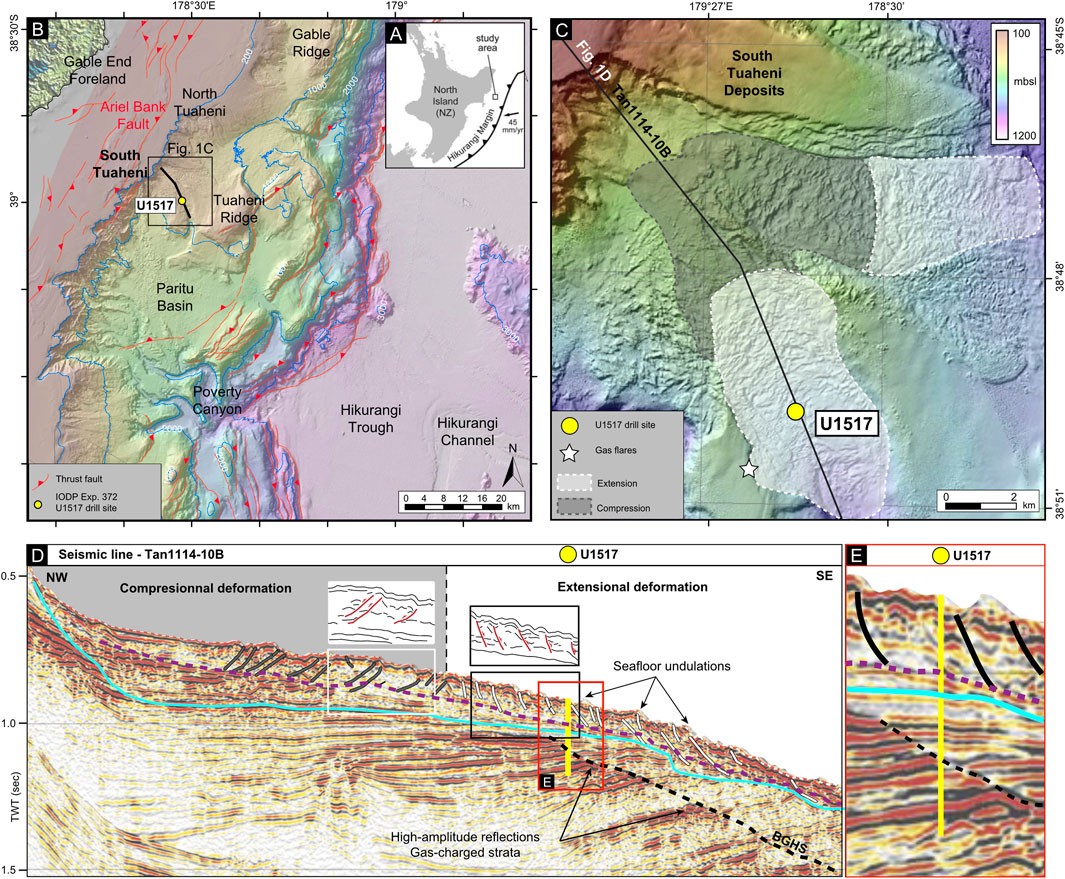
Figure 1. (A) Study area location in the Hikurangi margin, north-east of North Island of New Zealand; (B) Bathymetric map showing North and South Tuaheni location with thrust faults offshore and drill site U1517 from IODP Expedition 372 (November 2017 – January 2018, Pecher et al., 2019); (C) Zoom on the two South Tuaheni lobes and their rough surficial morphology, displaying uncommon extensional deformation (slight white) downstream displaying uncommon extensional deformation (slight gray) downstream and compressional deformation (slight gray) upstream. Drill site U1517 is located into the extensional deformation zone. Gas flares detected on the edges of Tuaheni South Deposit during the RV Tangaroa cruise TAN1404 (Gross et al., 2018); (D) Seismic line crossing the Tuaheni South Deposit from NW to SE, illustrating both the compressional and extensional deformations zones, location of drill site U1517, the intra-debris reflector from Gross et al., 2018 (dashed purple line), base of the Tuaheni South Deposit (turquoise blue line) and the Basal Gas Hydrate Surface (BGHS; dashed black line). Gas-charged strata are identified below the BGHS so as seafloor undulations at deposits’s surface; (E) Zoom on the U1517 drill site which cored key structural interfaces. Bathymetric (C) and seismic (D, E) illustrations modified from Mountjoy et al. (2014).
A key feature of this margin is the Tuaheni Landslide Complex (TLC), located on the upper slope near Poverty Bay (Figures 1B, C). The TLC is one of the most extensive and well-documented submarine landslide systems offshore New Zealand, comprising a series of mass-transport deposits that exhibit morphological and geophysical evidence of past - and potentially ongoing - slope failure (Mountjoy et al., 2014; Couvin et al., 2020).
IODP Site U1517 intersects the TLC and lies within the gas hydrate stability zone (GHSZ). The GHSZ defines the depth range within which gas hydrate is thermodynamically stable; at Site U1517, this zone extends from 650 m below sea level to ∼162 m below seafloor, as constrained by geophysical and geochemical data (Figure 1D; Mountjoy et al., 2014; Gross et al., 2018; Pecher et al., 2019).
In this study, we combine geochemical and X-CT datasets from sediment cores collected during the IODP Expedition 372 to investigate gas hydrate occurrence in the TLC offshore New Zealand (Figure 1E). We report, for the first-time, evidence of gas hydrate-filled fractures at very shallow depths within the SMTZ, and we discuss this unique observation regarding (1) the potential for similar fractures in other gas hydrate systems worldwide, (2) the analytical implications for future marine gas hydrate investigations, and (3) the possible consequences for climate-sensitive regions.
2 Materials and methods
2.1 Sediment cores from IODP expedition 372
IODP Expedition 372 Site U1517 was designed to log and sample through both the Tuaheni Landslide Complex and the gas hydrate stability zone (Figure 1; Pecher et al., 2019; Wallace et al., 2019). This study utilizes data from two holes drilled at the site. Hole U1517-A was drilled in 725 m of water depth using logging-while-drilling (LWD) tools to a depth of 205 mbsf. In Hole U1517-C, 188.5 m of sediments were recovered using the advanced piston corer (APC) and half-length APC (HLAPC). These two holes crossed the entire thickness of the TLC, from the seafloor down to the base at approximately 70 mbsf, and intersected the bottom simulating reflection (BSR) at ∼162 mbsf. High-resolution core photographs from the Expedition were modified and enhanced applying histogram equalization in Corel PHOTO-PAINT® software. This processing method improves the visibility of color contrasts, thus helping in the identification of lithofacies, deformation structures and sedimentary features. It may also produce slightly artificial colors. The processed images were used for visual interpretation of the core sedimentology.
2.2 Pore water geochemistry analyses
During IODP Expedition 372, pore water geochemistry analyses included chloride concentration (Cl−), sulfate (SO42−) and methane (CH4). Pore water was extracted from sediment cores using Rhizon samplers or a hydraulic press for squeezing, depending on sediment compaction and water content (Manheim, 1966; Dickens et al., 1995). Chloride concentrations were measured using ion chromatography, with deviations from seawater values used as indicators of gas hydrate presence or dissociation (Egeberg and Dickens, 1999). Sulfate concentrations were determined using spectrophotometric methods, allowing for the identification of the sulfate-methane transition zone (SMTZ), which marks the depth at which microbial anaerobic oxidation of methane (AOM) occurs (Borowski et al., 1996; Treude et al., 2003). Methane concentrations were quantified using gas chromatography (GC), where headspace gas samples were taken immediately after core recovery to minimize methane loss (Claypool and Kvenvolden, 1983; Pimmel and Claypool, 2001). These geochemical measurements provided crucial insights into gas hydrate occurrence and associated biogeochemical processes along the Hikurangi subduction margin (Crutchley et al., 2018; Pecher et al., 2019).
2.3 X-ray computed tomography (X-CT)
X-CT is a non-destructive imaging technique that generates high-resolution, three-dimensional representations of internal structures based on the differential attenuation of X-rays by the materials of varying density and composition. This method is particularly effective for sediment cores analysis, as it reveals micro-scale deformation structures, subtle density variations, and sedimentary features that are often invisible to the naked eye (Cnudde and Boone, 2013).
For this study, the archival half core from Hole U1517-C was scanned using a Neurologica CereTom system at Ohio State University, to image the sediment interval from 0 to 71 mbsf. The scanner resolution is 0.5 × 0.5 × 0.625 mm. All scans were performed with a peak energy of 100 keV, providing sufficient contrast to resolve density variations associated with subtle lithological changes and deformation features. On the selected display scale, high-density materials appear white, while low-density materials such as air appear dark, making density contrasts–particularly between sediments and air-filled features–clearly visible.
The X-CT data were processed and visualized using the open-source software FIJI®. Pre-processing steps included image alignment, noise reduction, and contrast enhancement to optimize the visibility of fine-scale features. Three-dimensional reconstructions and orthogonal slices were generated to facilitate the identification of fluid escape features and other sedimentary structures.
To estimate hydrate content, fracture volumes were quantified by segmenting the fractures using a thresholding approach. The area of the thresholded regions was divided by the total image area to calculate the relative hydrate fraction. This ratio was then applied to the total bulk volume of the core segment to estimate the absolute volume of hydrate-filled fractures.
3 Results
3.1 Fluid geochemistry
3.1.1 Gas hydrate occurrence
Chloride concentration measurements at Site U1517 provide clear evidence of gas hydrate presence below 81 mbsf. During core recovery, gas hydrate dissociates due to pressure and temperature changes, releasing freshwater that dilutes pore water chloride. At Site U1517, a notable decrease in chloride concentrations between 81 and 179 mbsf is interpreted as a signal of gas hydrate intervals above ∼162 mbsf and free gas below, consistent with the base of the hydrate stability zone established as approximately 162 mbsf (Figure 2A; Pecher et al., 2019). Gas hydrate saturation (Sh, expressed as a percentage of pore space; Figure 2B) was estimated using the LWD data. Calculated saturation values range from 2% to 68% between 136 and 165 mbsf, with gas hydrate predominantly concentrated in centimeter-thick, coarse-grained sand layers.
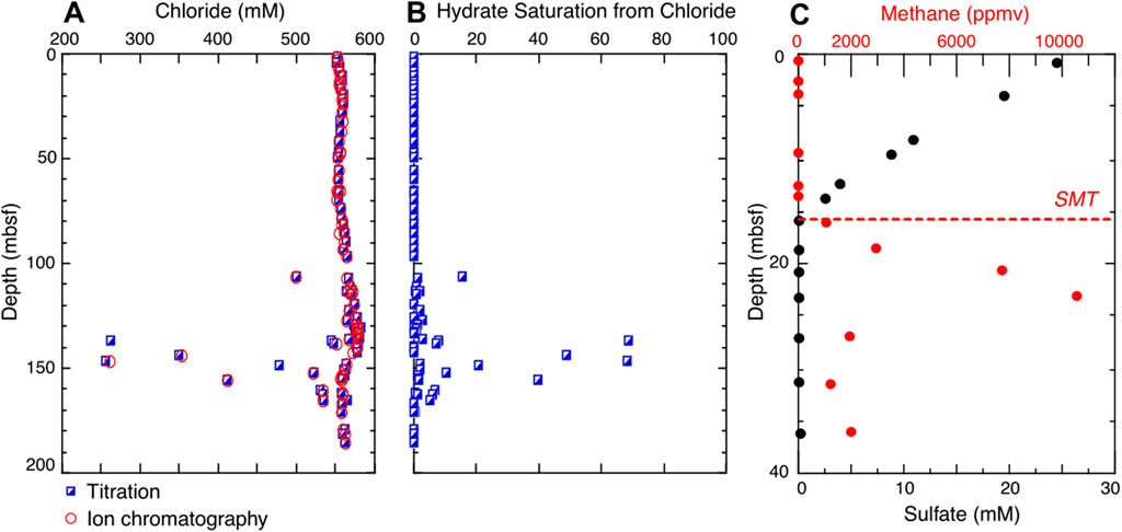
Figure 2. (A) Chloride profile at Site U1517 (titration and IC: Ion chromatography). Gas hydrate dissociation is indicated by low chloride values (due to core retrieval) and are used to estimate (B) Values of gas hydrate saturation from chloride. (C) Sulphate and methane profiles in the upper 40 m of Hole U1517C. The SMT (Sulphate Methane Transition) is illustrated by a dashed line and is indicative of where sulfate is consumed and methane is produced and increases with depth (Pecher et al., 2019).
3.1.2 Headspace methane analyses
At Site U1517, methane concentrations in headspace gas samples remain indistinguishable from instrumental blanks (approximately 2 ppmv) from 0 to 15 mbsf, indicating limited methanogenesis in the shallow sediments. This interval corresponds to the sulfate-rich zone, where microbial sulfate reduction inhibits the accumulation of biogenic methane.
Below approximately 17 mbsf, methane concentrations rise sharply, reaching up to 10,000 ppmv at 24 mbsf, indicating active microbial methanogenesis (Figure 2C). This depth coincides with the approximate location of the base the sulfate-methane transition zone, where sulfate becomes depleted and allows methane production to dominate (Borowski et al., 1996; Dickens, 2001). It is important to note that methane measurements provide only qualitative estimates of the in situ methane concentrations, as gas loss during core recovery, expansion, and hydrate dissociation can significantly alter the original methane content.
3.2 X-CT scans
No macroscopic evidence of gas hydrates was observed during core description, which motivated further investigation using X-CT scanning to detect sedimentary structures and features that are not discernible through conventional visual inspection alone.
3.2.1 Low-density, near-vertical structures
From 17 to 19.6 mbsf (cores U1517C-3F2 to U1517C-3F4), X-CT data reveal a large number of small, low-density, near-vertical structures (Figures 3, 4). Most of these structures exhibit wispy or diffuse boundaries–on our selected grayscale display, low-density materials such as air appear dark, while high-density materials appear white. The structures vary in size, with widths ranging from 0.5 to 5 mm, vertical extents between 7 and 60 mm, and dip angles between 45° and 90°. A total of approximately 150 fractures were identified, although structures near or thinner than the scanner’s minimum voxel size are difficult to detect, making it likely that not all structures were identified.
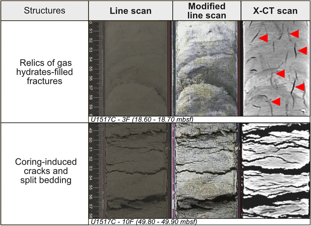
Figure 3. Illustrations of relics of gas hydrate filled-fractures (indicated by red markers) differing from coring disturbances such as cracks and split bedding identified in U1517-C core. Typical example is a composite of line scan, modified line scan (histogram equalization) and X-ray CT frontal view images. Corresponding cores and depth below seafloor (mbsf) are notified.
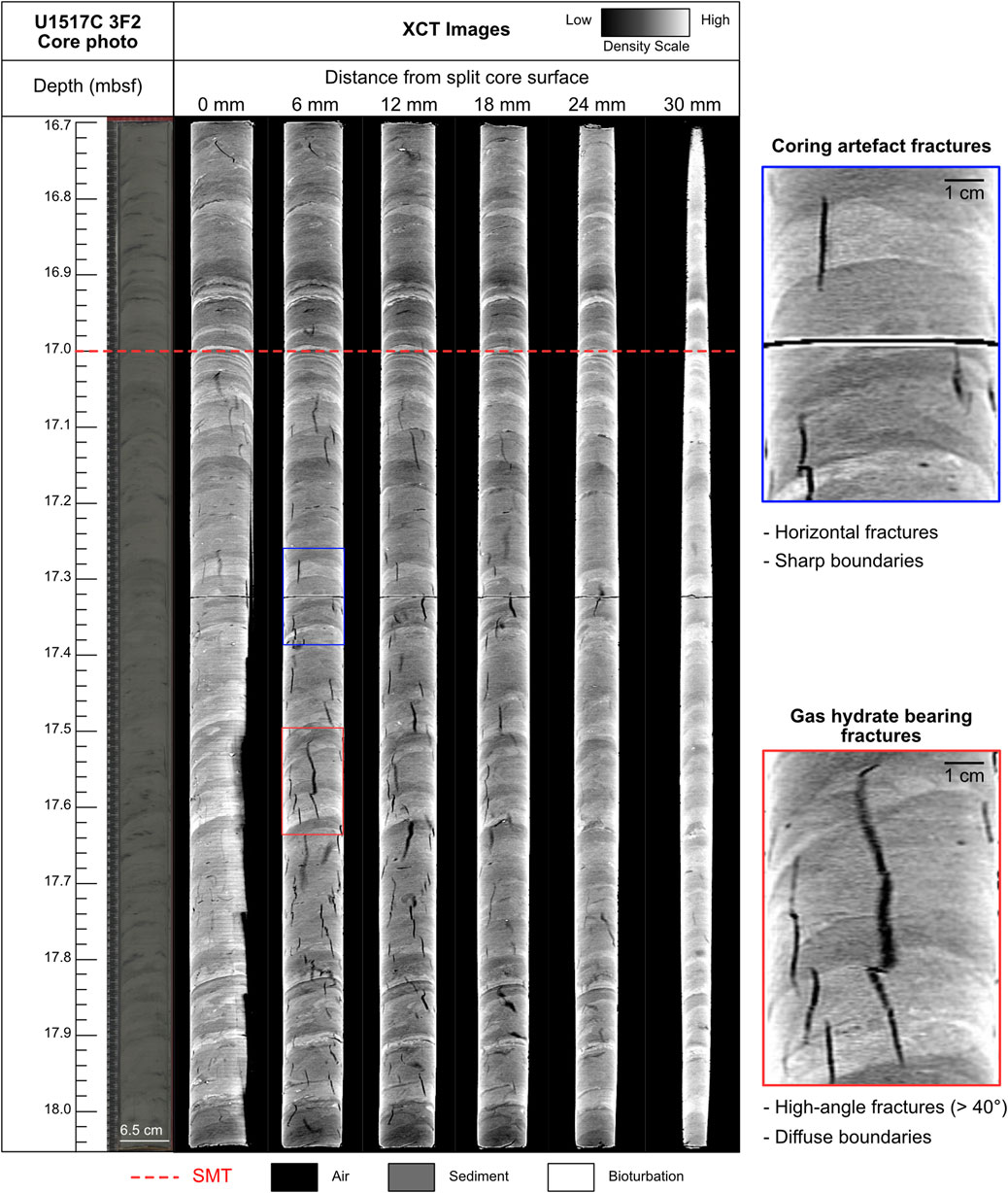
Figure 4. Composite illustration of the U1517-C 3F2 core photo next to series of 2D X-CT image slices progressing farther from split core surface. Density scale shows low-density features in dark and high-density features in bright. The surface (top slice) and bottom (rounded bottom slice) image display larger dark areas because of the irregular surface of the core. Interpreted gas hydrates-filled fractures are outlined in red based on specific identification criteria: diffuse boundaries, low-density and high-angle fractures (Oti et al., 2019), while coring-induced fractures are outlined in are outlined in blue. Note: The Sulphate Methane Transition (SMT) measured at 17 mbsf at site U1517 (Pecher et al., 2019) is annotated by a red dashed line.
These structures are most developed around 17 mbsf (Figures 3, 4), coinciding with the top of the sulfate-methane transition zone (SMTZ). Three-dimensional reconstructions of fractures (Figure 5) show a network of small, thin, subvertical structures with wispy edges, consistent with previous descriptions of hydrate-filled fractures (e.g., Oti et al., 2019). These fractures are clearly distinguishable from coring-induced artifacts, which typically appear as sub-horizontal, sharp fractures (Figure 3), and are colored in blue for comparison in Figure 5.
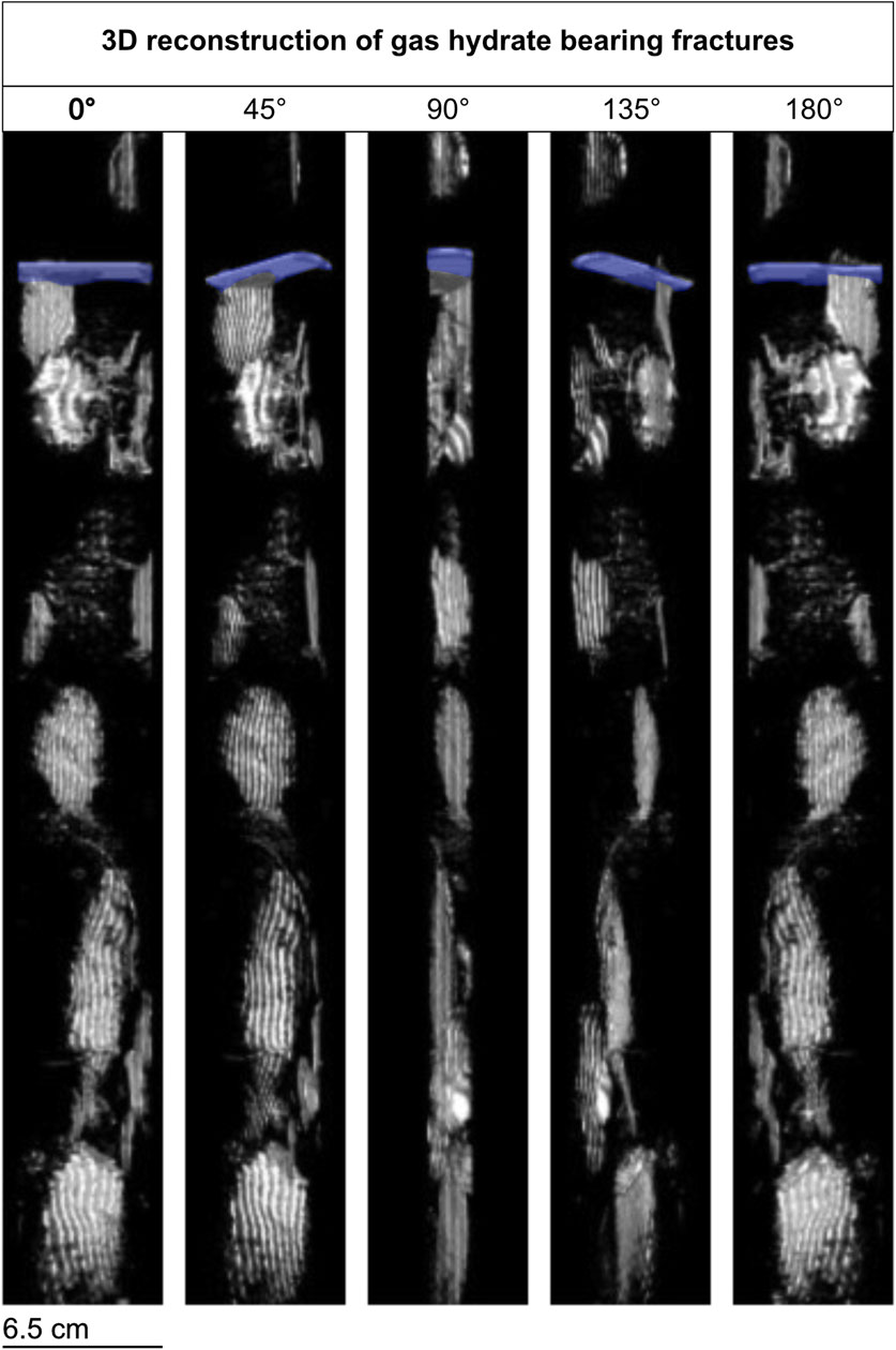
Figure 5. 3D reconstruction of relic gas hydrate-bearing fractures segmented from X-CT scans in the U1517-C 3F2 core. Core orientation is indicated from 0° to 180°. The coring-induced fracture is shown in blue, consistent with Figure 3. The reconstruction highlights typical features of gas hydrate-bearing fractures as described by Oti et al. (2019): near-vertical orientation, thin geometry, and wispy, diffuse edges. X-CT slices, acquired at 500 µm intervals, are also displayed.
4 Discussion
4.1 Hydrate filled-fractures forming at the SMTZ
At Site U1517, the gas hydrate stability zone extends from approximately 650 m below sea level (mbsl) to 162 m below seafloor (mbsf), as constrained by geophysical and geochemical data (Mountjoy et al., 2014; Gross et al., 2018; Pecher et al., 2019). In Hole U1517-C, we identified potential relic of gas hydrate filled-fractures between 17 and 19.6 mbsf, well within the gas hydrate stability zone (Figure 6). These fractures are observed in fine-grained, clay-rich sediments (Figures 3, 4, 6) and exhibit distinct characteristics consistent with features previously described gas-hydrate-filled fractures (Oti et al., 2019). These planar features are characterized by near-vertical angles, diffuse edges and localized low-density relative to the surrounding sediment matrix, as the fractures are now open and air-filled. Based on the dimensions of the observed fractures, we estimate that the fractures occupy approximately 2.2% of the bulk volume, which is equivalent to a hydrate saturation of ∼5%, assuming a porosity of 45%.
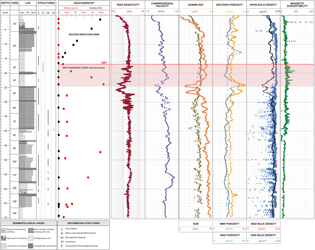
Figure 6. Synthetic illustration integrating lithological, structural and geochemical analyses of U1517-C cores down to 71.5 mbsf. Sedimentological facies, deformation structures are also indicated. Physical properties measured on core U1517-C including compressional wave velocity, Natural Gamma Radiation (NGR), porosity (MAD), Gamma Ray Attenuation (GRA), bulk density (MAD), and magnetic susceptibility are illustrated. In addition, Logging-While-Drilling (LWD) data from Site U1517-A, such as ring resistivity, gamma ray, neutron and NMR porosity, and bulk density (RHON), are shown for comparison.
At Site U1517, the SMTZ was identified at approximately 17 mbsf (Pecher et al., 2019; Figures 2, 6). Methane can accumulate below this depth, where sulfate is depleted and microbial oxidation is no longer active, creating favorable conditions for gas hydrate formation (Borowski et al., 1999; Ruppel and Kessler, 2017). Although we did not measure microbial activity directly, methanogenesis rates reported from sulfate-depleted marine sediments typically range from 0.1 to 10 nmol CH4 cm−3 day−1 (e.g., Egger et al., 2018). At such rates, sufficient methane could accumulate locally over timescales of hundreds to thousands of years to reach saturation and allow for hydrate formation under favorable pressure-temperature conditions. This supports the plausibility of local methane production as a contributing source, particularly near the SMTZ. We suggest that in this setting, hydrate formation may result from the combined effects of short-range methane migration via fractures and localized microbial production. In addition, the co-occurrence of these relic fractures and the SMTZ strongly suggests that hydrate formation occurred in situ during early diagenesis. Although gas hydrate was not physically recovered from the core, the morphology of these relic fractures is similar to that of gas bearing fractures observed in other settings. It is likely that the gas hydrate dissociated shortly after core recovery.
While we interpret these vertical, low-density structures as relics of hydrate-filled fractures based on their planar morphology, vertical orientation, and occurrence near the SMTZ, we acknowledge that similar features may potentially result from other processes. Gas hydrate formation within biomineralized burrows, for instance, has been shown to generate stress and propagate fractures (Oti et al., 2019), complicating the distinction between biogenic and fracture-related features when observed with X-CT alone. We are not aware of specific diagenetic processes that would generate such regular, vertically aligned structures in these sediments. Future work involving mineralogical and porewater analyses will be essential to further constrain the origin of these features.
4.2 Comparisons to other sites
In comparison to other locations where hydrate filled-fractures have been documented, the fractures at Site U1517 are significantly smaller in size and occur at significantly shallower depths. At Site U1517, fractures only extend up to 60 mm in length, whereas previously described relic hydrate-filled fractures commonly cut across the entire core, implying that the full extent of such fracture may not have been captured during coring (Oti et al., 2019). Similarly, gas hydrate filled-fractures identified in LWD data must cut across the borehole and extend beyond the borehole to be imaged by resistivity tools (e.g., Cook et al., 2014). These features are often hydrate filled-fractures visible for tens of centimeters to several meters as they intersect the borehole. In contrast, small-scale fractures like the ones observed in core U1517-C would likely not be captured in resistivity logs or resistivity images because the electrical current can bypass these narrow features and preferentially travel through the more conductive sediment matrix.
Hydrate filled-fractures at sites without active or paleo methane venting are typically found at significantly greater depths than those at Site U1517 (Table 1). The shallowest previously reported hydrate filled-fractures were identified in logging-while drilling resistivity images at 55 mbsf offshore India (Cook and Goldberg, 2008), while most occurrences of fractures are reported between 100 and 300 mbsf (Cook et al., 2014; Oti et al., 2019; Boswell and Collett, 2011). We hypothesize that the fractures observed at Site U1517 represent the early stages of gas hydrate filled-fractures development, which would explain their relatively small in size and unusually shallow depth. Over time, as sediments continue to accumulates on the seafloor and burial depth increases, these fractures may progressively deepen and evolve into larger structures (Figure 7).
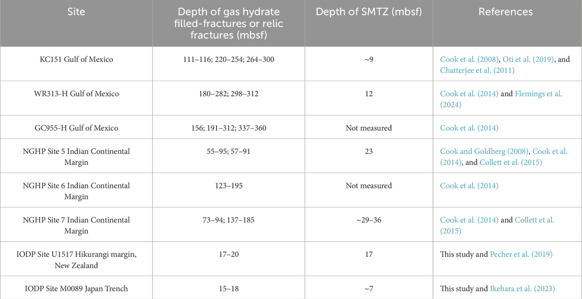
Table 1. The location, the depth and sulfate methane transition zone at sites with gas hydrate filled fractures.
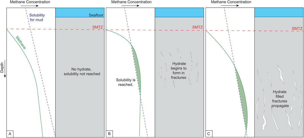
Figure 7. Cartoon showing hydrate filled fracture system formation at the sulfate-methane transition zone (SMTZ). (A) Below the SMTZ, annotated by a red dashed line, the solubility level of methane is not yet reached. (B) Once the methane exceeds the solubility needed for hydrate to form in mud, hydrate slowly starts forming in open pore space, creating small fractures. (C) As sedimentation continues, the hydrate filed fracture move deeper and propagate vertically.
To investigate whether similar hydrate filled-fractures may occur at or near the SMTZ in other locations, we reviewed all available X-CT scans of sediment cores from the publicly accessible archives of the International Ocean Discovery Program (IODP). Most expeditions either do not perform X-CT scanning on sediment cores or, when they do, rarely include shallow intervals encompassing the SMTZ. To our knowledge, only four other expeditions provided X-CT core scans that covered both the GHSZ and the SMTZ. Notably, all of these expeditions were conducted offshore Japan: one site from Expedition 315 (Ashi et al., 2009), one site from Expedition 322 (Underwood et al., 2010), one site from Expedition 358 (Tobin et al., 2020), and fifteen sites from Expedition 386 (Strasser et al., 2023).
We identified potential relic hydrate-filled fractures at six of these sites, all are located along the Japan Trench and recovered during IODP Expedition 386. Site M0089 provided the most compelling evidence for the presence of relic of gas hydrate-filled fractures. These fractures were observed in core M0089B-1H, specifically in sections 16, 17, and 18, between 15.9 and 17.9 mbsf, within clayey-silt sediments. These fractures (Figure 8) are slightly larger than those found at Site U1517, measuring 60.1 and 49.5 cm in length, and exhibit the same diffuse edges characteristic of hydrate filled-fractures previously discussed (Oti et al., 2019). Although these fractures are larger than the ones identified at Site U1517, they are located closer to the SMTZ than any previously documented hydrate-filled fractures (Table 1). The fractures occur at 8.7 m below the SMTZ, which is positioned at approximately 7 mbsf based on pore water geochemistry (Ikehara et al., 2023). The occurrence of such fractures along both the Japan and New Zealand subduction margins, near the SMTZ, suggests that hydrate filled-fractures may commonly develop in proximity to this diagenetic boundary, but remain underreported due to the limited availability of X-CT core data.
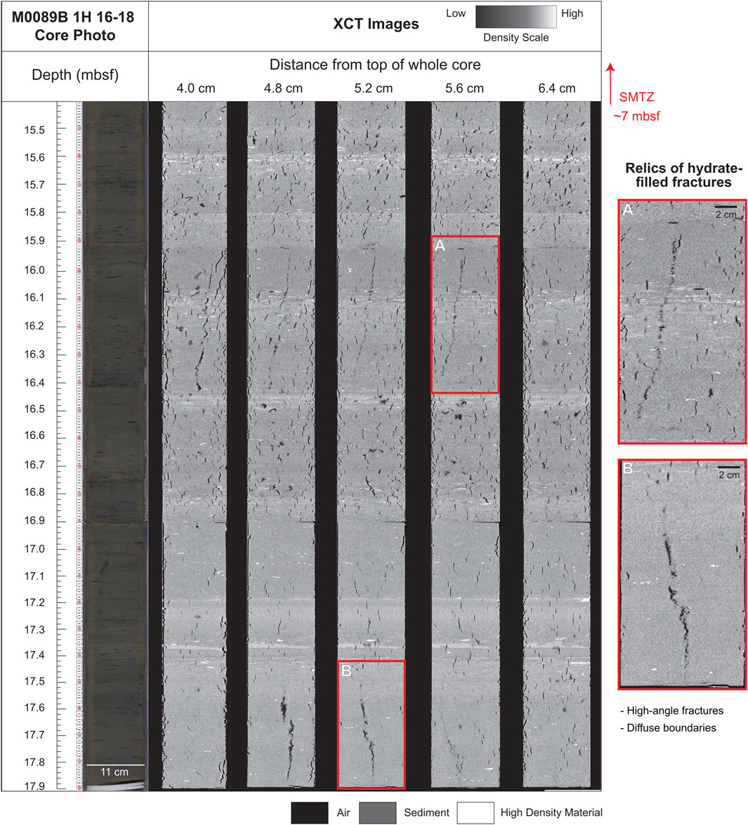
Figure 8. A composite illustration of the M0089B core photo next to series of 2D X-CT image slices progressing farther from top of the whole core surface. The density scale shows low-density features in black and high-density features in white. Interpreted relics of gas hydrate-filled fractures are identified based on specific identification criteria diffuse boundaries, low-density and high-angle fractures (Oti et al., 2019). Note: The sulfate-methane transition zone (SMTZ) measured at 7 mbsf at site M0089 (Ikehara et al., 2023) is annotated by a red dashed line.
4.3 Implications for near-seafloor fractures
We hypothesize that small, hydrate-filled fractures may commonly form at or near the SMTZ in clay-rich sediments. If more methane is available, these fractures could progressively grow over time. If this fracture-hosted mode of gas hydrate formation is widespread - particularly near-vertical fractures forming close to the SMTZ - it could have significant implications in climate-sensitive regions such as the Arctic, where shallow gas hydrates are more susceptible to dissociation due to environmental change.
Modeling studies and observational data suggest that even minor increases in bottom water temperature can lead to gas hydrate dissociation in shallow settings (Archer, 2007; Portnov et al., 2014; Ruppel and Kessler, 2017). If low saturation hydrate occurs in the primary pore space of sediment and dissociates, the resulting methane may not form a buoyant phase and would remain in the sediment (Daigle et al., 2019). Moreover, if methane forms a buoyant phase that moved through the pore space towards the seafloor, it would most likely be consumed by anaerobic oxidation of methane (AOM) within the sediment column (Beulig et al., 2018; Reeburgh, 2007). In contrast, methane released from hydrate-filled fractures is already present as a buoyant gas phase and may become over-pressurized upon dissociation. This over-pressured gas could rapidly propagate upward through the sediment, potentially fracturing its way toward the seafloor. In such a scenario, methane bypasses the AOM filter because gas-filled fractures can traverse the sediment column in a matter of seconds (Jin et al., 2004), increasing the likelihood of direct methane release into the ocean.
The presence and dissociation of hydrate-filled fractures challenges the classical view of methane migration as a purely diffusion-dominated process in fine-grained sediments. These fractures may create preferential pathways that promote focused methane transport and lead to spatially heterogeneous patterns of AOM activity. While our observations suggest that fractures may serve as focused conduits for methane transport leading to localized hydrate formation near the SMTZ, we recognize that this mechanism likely operates alongside slower, diffusive methane migration. The relative contribution of fracture flow versus diffusion may vary spatially and temporally, depending on factors such as sediment permeability, methane flux, and fracture connectivity. Our interpretation emphasizes the potential for transient, fracture-controlled pathways to deliver methane rapidly to shallow depths, without excluding the importance of diffusion in broader sedimentary settings. Over time, the gas hydrate growth in fractures and subsequent dissociation can alter the sediment fabric, porosity, and permeability, thereby influencing fluid flow and geochemical exchange in early diagenetic environments (Nimblett & Ruppel, 2003). Additionally, the formation, growth and eventually dissociation or dissolution of hydrate-filled fractures may impact the spatial distribution of microbial habitats and redox gradients, with potential consequences for microbial community structure and biogeochemical cycling (Treude et al., 2003).
4.4 Implications for future analytical approach of shallow gas hydrate activity
The present findings emphasize the need and importance of incorporating X-CT into sediment core analyses protocols, particularly in near-seafloor intervals at and around the SMTZ, where microbially sourced methane is abundant and early diagenetic processes are actively shaping the sedimentary record. Relic fractures preserve indirect evidence of past gas hydrate occurrence and dissociation, even when intact gas hydrate samples are no longer preserved. Moreover, high-resolution X-CT data in this interval can reveal sedimentary features such as bioturbation structures that are not discernible through conventional visual core description (e.g., Hovikoski et al., 2025).
Although small-scale fractures like those observed at Site U1517 are below the detection threshold of standard downhole logging tools (Figure 6), larger hydrate-filled fracture systems - such as those reported offshore India and in the Gulf of Mexico (Table 1) - may be identifiable through logging if present.
However, this study suggests that fractures can initiate much closer to the seafloor than previously documented, challenging current assumptions. In most cases, the first 50–100 m below the seafloor are not covered by logging data because the drill pipe is inserted to stabilize the borehole prior to logging. We propose that this standard practice has likely led to the oversight and consequent underestimation of the occurrence and extent of near-seafloor gas hydrate systems.
5 Conclusion
This study documents relic gas hydrate-filled fractures at unusually shallow depths, coinciding with the sulfate-methane transition zone (SMTZ), based on X-Computed Tomography (X-CT) scans of marine sediment cores from IODP Expedition 372 offshore New Zealand. These small, near-seafloor fractures likely represent early stages of hydrate formation, at and near the SMTZ. These fractures may continue to increase in size and in depth over time as microbial methane accumulates. The formation, dissociation or dissolution of hydrate filled fractures may alter sediment structure, influence fluid flow and shape microbial activities during early diagenesis. In addition, the presence of gas hydrate in fractures–unlike pore-filling hydrate–could rapidly release methane to the seafloor upon dissociation, especially in climate-sensitive regions like the Arctic. Similar features identified in sediment cores from Expedition 386 in the Japan Trench suggest such shallow hydrate-filled fractures may be more widespread than currently documented, but remain underreported due to the limited application of X-CT imaging in shallow intervals of scientific ocean drilling cores. While our interpretation is supported by geometry and context, it is primarily based on non-destructive imaging. Additional constraints such as direct sampling, geochemical analysis, and mineralogical validation are required to confirm the hydrate origin of these structures. Future research should also explore the relative roles of microbial methane production and fracture-mediated gas migration in shallow marine sediments.
Data availability statement
The raw data supporting the conclusion of this article will be made available by the authors, without undue reservation.
Author contributions
MB: Conceptualization, Project administration, Supervision, Funding acquisition, Validation, Writing – review and editing, Methodology, Software, Data curation, Writing – original draft, Investigation, Resources, Formal Analysis, Visualization. AC: Writing – review and editing, Investigation, Resources, Methodology, Validation. SM: Software, Visualization, Writing – review and editing, Validation, Formal Analysis, Methodology. JM: Funding acquisition, Writing – review and editing, Validation.
Funding
The author(s) declare that financial support was received for the research and/or publication of this article. This work was funded by the Bureau IODP-France and X-CT data acquisition was co-funded by Royal Society of New Zealand Marsden Grant NIW1603 and by NIWA through the Strategic Science Investment Fund from New Zealand’s Ministry for Business, Innovation and Employment. Ann Cook and Saffron Martin were funded by NSF Award #1752882.
Acknowledgments
The authors thank the scientific parties, technical staff, and crews of IODP Expeditions 372 onboard the R/V Joides Resolution for their collaboration and efficient work. We appreciate agreement from Tairahwiti iwi Te Runanga o Ngati Porou and Rongowhakaata to undertake field work offshore Tūranganui-a-kiwa. Data from the IODP Expedition 372 can be obtained through the expedition’s implementing organization USIO (http://iodp.tamu.edu/database). This research used samples and data provided by the International Ocean Discovery Program (IODP). The X-CT data from Japan can be accessed at: https://www.jamstec.co.jp/sio7/ and the X-CT data from ECORD can be accessed at: https://iodp.pangea.de/.
Conflict of interest
The authors declare that the research was conducted in the absence of any commercial or financial relationships that could be construed as a potential conflict of interest.
Correction note
A correction has been made to this article. Details can be found at: 10.3389/feart.2025.1671888.
Generative AI statement
The author(s) declare that no Generative AI was used in the creation of this manuscript.
Publisher’s note
All claims expressed in this article are solely those of the authors and do not necessarily represent those of their affiliated organizations, or those of the publisher, the editors and the reviewers. Any product that may be evaluated in this article, or claim that may be made by its manufacturer, is not guaranteed or endorsed by the publisher.
References
Archer, D. (2007). Methane hydrate stability and anthropogenic climate change. Biogeosciences 4 (4), 521–544. doi:10.5194/bg-4-521-2007
Ashi, J., Lallemant, S., and Masago, H.Expedition 315 Scientists (2009). “Expedition 315 summary,” in Proc. IODP, 314–315/316.
Barnes, P. M., Wallace, L. M., Saffer, D. M., Bell, R. E., Underwood, M. B., Fagereng, A., et al. (2020). Slow slip source characterized by lithological and geometric heterogeneity. Sci. Adv. 6 (13), eaay3314. doi:10.1126/sciadv.aay3314
Beulig, F., Røy, H., Glombitza, C., and Jørgensen, B. B. (2018). Control on rate and pathway of anaerobic organic carbon degradation in the seabed. Proc. Natl. Acad. Sci. 115 (2), 367–372. doi:10.1073/pnas.1715789115
Boetius, A., Ravenschlag, K., Schubert, C. J., Rickert, D., Widdel, F., Gieseke, A., et al. (2000). A marine microbial consortium apparently mediating anaerobic oxidation of methane. Nature 407 (6804), 623–626. doi:10.1038/35036572
Borowski, W. S., Paull, C. K., and Ussler, W. (1996). Marine pore-water sulfate profiles indicate in situ methane flux from underlying gas hydrate. Geology 24 (7), 655–658. doi:10.1130/0091-7613(1996)024<0655:mpwspi>2.3.co;2
Borowski, W. S., Paull, C. K., and Ussler Iii, W. (1999). Global and local variations of interstitial sulfate gradients in deep-water, continental margin sediments: sensitivity to underlying methane and gas hydrates. Mar. Geol. 159 (1-4), 131–154. doi:10.1016/s0025-3227(99)00004-3
Boswell, R., and Collett, T. S. (2011). Current perspectives on gas hydrate resources. Energy and Environ. Sci. 4 (4), 1206–1215. doi:10.1039/c0ee00203h
Bowles, M. W., Mogollón, J. M., Kasten, S., Zabel, M., and Hinrichs, K. U. (2014). Global rates of marine sulfate reduction and implications for sub–sea-floor metabolic activities. Science 344 (6186), 889–891. doi:10.1126/science.1249213
Burton, D. R., Saffer, D. M., Pecher, I. A., Barnes, P. M., Burgreen Chan, B., and Graham, S. A. (2020). Tectonic uplift destabilizes subsea gas hydrate: a model example from Hikurangi Margin, New Zealand. Geophys. Res. Lett. 47 (12), e2020GL087150. doi:10.1029/2020gl087150
Chatterjee, S., Dickens, G. R., Bhatnagar, G., Chapman, W. G., Dugan, B., Snyder, G. T., et al. (2011). Pore water sulfate, alkalinity, and carbon isotope profiles in shallow sediment above marine gas hydrate systems: a numerical modeling perspective. J. Geophys. Res. Solid Earth 116 (B9), B09103. doi:10.1029/2011jb008290
Claussmann, B., Bailleul, J., Chanier, F., Mahieux, G., McArthur, A. D., and Vendeville, B. C. (2023). Early stages of trench-slope basin development: insights from mass-transport deposits and their interactions with turbidite systems (southern Hikurangi margin, New Zealand). Mar. Petroleum Geol. 152, 106191. doi:10.1016/j.marpetgeo.2023.106191
Claypool, G. E., and Kvenvolden, K. A.(1983). Methane and other hydrocarbon gases in marine sediment. Annu. Rev. Earth Planet. Sci. 11, 299.
Cnudde, V., and Boone, M. N. (2013). High-resolution X-ray computed tomography in geosciences: a review of the current technology and applications. Earth-Science Rev. 123, 1–17. doi:10.1016/j.earscirev.2013.04.003
Collett, T., Riedel, M., Cochran, J., Boswell, R., Presley, J., Kumar, P., et al. (2015). “The NGHP expedition scientists,” in Indian national gas hydrate Program expedition 01 report. U.S. Geological Survey Scientific Investigations Report 2012–5054, 1442.
Cook, A. E., and Goldberg, D. (2008). Extent of gas hydrate filled fracture planes: implications for in situ methanogenesis and resource potential. Geophys. Res. Lett. 35 (15). doi:10.1029/2008gl034587
Cook, A. E., Goldberg, D., and Kleinberg, R. L. (2008). Fracture-controlled gas hydrate systems in the northern Gulf of Mexico. Mar. Petroleum Geol. 25 (9), 932–941. doi:10.1016/j.marpetgeo.2008.01.013
Cook, A. E., Goldberg, D. S., and Malinverno, A. (2014). Natural gas hydrates occupying fractures: a focus on non-vent sites on the Indian continental margin and the northern Gulf of Mexico. Mar. Petroleum Geol. 58, 278–291. doi:10.1016/j.marpetgeo.2014.04.013
Couvin, B., Georgiopoulou, A., Mountjoy, J. J., Amy, L., Crutchley, G. J., Brunet, M., et al. (2020). A new depositional model for the Tuaheni landslide complex, Hikurangi margin, New Zealand 500, 551–566. doi:10.1144/sp500-2019-180
Crutchley, G. J., Pecher, I. A., Gorman, A. R., Henrys, S. A., and Greinert, J. (2018). The potential influence of shallow gas and gas hydrates on sea floor erosion of Rock Garden, an uplifted ridge offshore of New Zealand. Geo-Marine Lett. 30, 283–303. doi:10.1007/s00367-010-0186-y
Daigle, H., and Dugan, B. (2010). Origin and evolution of fracture hosted methane hydrate deposits. J. Geophys. Res. Solid Earth 115 (B11). doi:10.1029/2010jb007492
Daigle, H., Reece, J. S., and Flemings, P. B. (2019). Evolution of the percolation threshold in muds and mudrocks during burial. Geophys. Res. Lett. 46 (14), 8064–8073. doi:10.1029/2019gl083723
Davie, M. K., and Buffett, B. A. (2001). A numerical model for the formation of gas hydrate below the seafloor. J. Geophys. Res.: Solid Earth. 106 (B1), 497–514
Dickens, G. R. (2001). Sulfate profiles and barium fronts in sediment on the Blake Ridge: present and past methane fluxes through a large gas hydrate reservoir. Geochimica Cosmochimica Acta 65 (4), 529–543. doi:10.1016/s0016-7037(00)00556-1
Dickens, G. R., O'Neil, J. R., Rea, D. K., and Owen, R. M. (1995). Dissociation of oceanic methane hydrate as a cause of the carbon isotope excursion at the end of the Paleocene. Paleoceanography 10 (6), 965–971. doi:10.1029/95pa02087
Egeberg, P. K., and Dickens, G. R. (1999). Thermodynamic and pore water halogen constraints on gas hydrate distribution at ODP Site 997 (Blake Ridge). Chem. Geol. 153 (1-4), 53–79. doi:10.1016/s0009-2541(98)00152-1
Egger, M., Riedinger, N., Mogollón, J. M., and Jørgensen, B. B. (2018). Global diffusive fluxes of methane in marine sediments. Nat. Geosci. 11 (6), 421–425. doi:10.1038/s41561-018-0122-8
Flemings, P. B., Thomas, C., Phillips, S. C., Collett, T. S., Cook, A. E., Solomon, E., et al. (2024). UT-GOM2-2 preliminary report terrebonne basin northern Gulf of Mexico.
Gross, F., Mountjoy, J. J., Crutchley, G. J., Böttner, C., Koch, S., Bialas, J., et al. (2018). Free gas distribution and basal shear zone development in a subaqueous landslide–Insight from 3D seismic imaging of the Tuaheni Landslide Complex, New Zealand. Earth Planet. Sci. Lett. 502, 231–243. doi:10.1016/j.epsl.2018.09.002
Hovikoski, J., Virtasalo, J. J., Wetzel, A., Muthre, M., Strasser, M., Proust, J. N., et al. (2025). Bioturbation in the hadal zone. Nat. Commun. 16 (1), 1401. doi:10.1038/s41467-025-56627-x
Ikehara, K., Strasser, M., Everest, J., Maeda, L., and Hochmuth, K.Expedition 386 Scientists (2023). Expedition 386 preliminary report: Japan trench paleoseismology. Int. Ocean. Discov. Program. doi:10.14379/iodp.pr.386.2023
Jin, S., Takeya, S., Hayashi, J., Nagao, J., Kamata, Y., Ebinuma, T., et al. (2004). Structure analyses of artificial methane hydrate sediments by microfocus X-ray computed tomography. Jpn. J. Appl. Phys. 43 (8R), 5673. doi:10.1143/jjap.43.5673
Kim, G. Y., Yi, B. Y., Yoo, D. G., Ryu, B. J., and Riedel, M. (2011). Evidence of gas hydrate from downhole logging data in the Ulleung Basin, East Sea. Mar. Petroleum Geol. 28 (10), 1979–1985. doi:10.1016/j.marpetgeo.2011.01.011
Kroeger, K. F., Crutchley, G. J., Kellett, R., and Barnes, P. M. (2019). A 3-D model of gas generation, migration, and gas hydrate formation at a young convergent margin (Hikurangi margin, New Zealand). Geochem. Geophys. Geosystems 20 (11), 5126–5147. doi:10.1029/2019gc008275
Kvenvolden, K. A. (1993). Gas hydrates—geological perspective and global change. Rev. Geophys. 31 (2), 173–187. doi:10.1029/93rg00268
Malinverno, A., and Pohlman, J. W. (2011). Modeling sulfate reduction in methane hydrate bearing continental margin sediments: does a sulfate methane transition require anaerobic oxidation of methane? Geochem. Geophys. Geosystems 12 (7). doi:10.1029/2011gc003501
Manheim, F. T. (1966). A hydraulic squeezer for obtaining interstitial water from consolidated and unconsolidated sediments. U. S. Geol. Surv. Prof. Pap. 550, 256–261.
Milkov, A. V. (2011). Worldwide distribution and significance of secondary microbial methane formed during petroleum biodegradation in conventional reservoirs. Org. Geochem. 42 (2), 184–207. doi:10.1016/j.orggeochem.2010.12.003
Mountjoy, J. J., Pecher, I., Henrys, S., Crutchley, G., Barnes, P. M., and Plaza Faverola, A. (2014). Shallow methane hydrate system controls ongoing, downslope sediment transport in a low velocity active submarine landslide complex, Hikurangi Margin, New Zealand. Geochem. Geophys. Geosystems 15 (11), 4137–4156. doi:10.1002/2014gc005379
Nimblett, J., and Ruppel, C. (2003). Permeability evolution during the formation of gas hydrates in marine sediments. J. Geophys. Res. Solid Earth 108 (B9). doi:10.1029/2001jb001650
Oti, E. A., Cook, A. E., Welch, S. A., Sheets, J. M., Crandall, D., Rose, K., et al. (2019). Hydrate filled fracture formation at Keathley Canyon 151, Gulf of Mexico, and implications for non vent sites. Geochem. Geophys. Geosystems 20 (11), 4723–4736. doi:10.1029/2019gc008637
Pecher, I. A., Barnes, P. M., and LeVay, L. J. (2019). Creeping gas hydrate slides. Proc. Int. Ocean Discov. Program 372. doi:10.14379/iodp.proc.372A.2019
Pimmel, A., and Claypool, G. (2001). Introduction to shipboard organic geochemistry on the JOIDES resolution.
Plaza-Faverola, A., Pecher, I. A., Klaeschen, D., Henrys, S., Gorman, A., and Mountjoy, J. (2012). Evolution of fluid expulsion and concentrated hydrate zones across the southern Hikurangi subduction margin, New Zealand: an analysis from depth migrated seismic data. Geochem. Geophys. Geosystems 13 (8), Q08018. doi:10.1029/2012gc004228
Portnov, A., Mienert, J., and Serov, P. (2014). Modeling the evolution of climate sensitive Arctic subsea permafrost in regions of extensive gas expulsion at the West Yamal shelf. J. Geophys. Res. Biogeosciences 119 (11), 2082–2094. doi:10.1002/2014jg002685
Reeburgh, W. S. (2007). Oceanic methane biogeochemistry. Chem. Rev. 107 (2), 486–513. doi:10.1021/cr050362v
Ruppel, C. D., and Kessler, J. D. (2017). The interaction of climate change and methane hydrates. Rev. Geophys. 55 (1), 126–168. doi:10.1002/2016rg000534
Strachan, L. J., Bailleul, J., Bland, K. J., Orpin, A. R., and McArthur, A. D. (2022). Understanding sedimentary systems and processes of the Hikurangi subduction margin; from trench to back-Arc. Volume 1. N. Z. J. Geol. Geophys. 65 (1), 1–16. doi:10.1080/00288306.2022.2048032
Strasser, M., Ikehara, K., and Everest, J.the Expedition 386 Scientists (2023). Expedition 386 summary. Proc. IODP 386. doi:10.14379/iodp.proc.386.2023
Tobin, H., Hirose, T., Ikari, M., Kanagawa, K., Kimura, G., and Kinoshita, M. (2020). “Expedition 358 summary,” in Proc. IODP, 358.
Treude, T., Boetius, A., Knittel, K., Wallmann, K., and Jørgensen, B. B. (2003). Anaerobic oxidation of methane above gas hydrates at hydrate ridge, NE Pacific ocean. Mar. Ecol. Prog. Ser. 264, 1–14. doi:10.3354/meps264001
Underwood, M. B., Saito, S., and Kubo, Y.the Expedition 322 Scientists (2010). “Expedition 322 summary,” in Proc. IODP, 322.
Waite, W. F., Santamarina, J. C., Cortes, D. D., Dugan, B., Espinoza, D. N., Germaine, J., et al. (2009). Physical properties of hydrate-bearing sediments. Rev. Geophys. 47 (4), 1–38. doi:10.1029/2008rg000279
Wallace, L. M., Reyners, M., Cochran, U., Bannister, S., Barnes, P. M., Berryman, K., et al. (2009). Characterizing the seismogenic zone of a major plate boundary subduction thrust: Hikurangi Margin, New Zealand. Geochem. Geophys. Geosystems 10 (10). doi:10.1029/2009gc002610
Wallace, L. M., Saffer, D. M., Barnes, P. M., Pecher, I. A., Petronotis, K. E., and LeVay, L. J. (2019). Hikurangi subduction margin coring, logging, and observatories. Proc. Int. ocean Discov. program 372.
Weinberger, J. L., and Brown, K. M. (2006). Fracture networks and hydrate distribution at Hydrate Ridge, Oregon. Earth Planet. Sci. Lett. 245 (1–2), 123–136. doi:10.1016/j.epsl.2006.03.012
Keywords: gas hydrate, sulfate-methane transition zone, fracture network, X-ray computed tomography, Hikurangi subduction margin, New Zealand, IODP expedition 372
Citation: Brunet M, Cook A, Martin S and Mountjoy J (2025) Evidence for gas hydrate-filled fractures forming at the sulfate-methane transition zone, Hikurangi subduction margin, New Zealand. Front. Earth Sci. 13:1630118. doi: 10.3389/feart.2025.1630118
Received: 16 May 2025; Accepted: 10 June 2025;
Published: 14 July 2025; Corrected: 29 August 2025.
Edited by:
Maria De La Fuente, Université libre de Bruxelles, BelgiumReviewed by:
Zhengzheng Cao, Henan Polytechnic University, ChinaKehua You, The University of Texas at Austin, United States
Copyright © 2025 Brunet, Cook, Martin and Mountjoy. This is an open-access article distributed under the terms of the Creative Commons Attribution License (CC BY). The use, distribution or reproduction in other forums is permitted, provided the original author(s) and the copyright owner(s) are credited and that the original publication in this journal is cited, in accordance with accepted academic practice. No use, distribution or reproduction is permitted which does not comply with these terms.
*Correspondence: Morgane Brunet, bW9yZ2FuZS5icnVuZXRAdXFhci5jYQ==