 Shengji Xu1,2
 Qingcong Zhou
- 1School of Mines, China University of Mining and Technology, Xuzhou, China
- 2Shaanxi Yanchang Petroleum Yulin Kekegai Coal Industry Limited, Yulin, China
This study addresses the critical challenge of maintaining surrounding rock stability in the large-section open-off cuts with composite roofs, using the 11211 working face in Yanchang Petroleum Kekegai Coal Mine as a case study. Through integrated field measurements, theoretical analysis, numerical modeling, and industrial experiments, we systematically examine the failure mechanisms of surrounding rock and propose corresponding control strategies. Key findings include: 1) The composite roof exhibits weak interlayer bonding and undergoes progressive bending-delamination-fracture failure under stress, requiring a high-strength coupled support system. 2) Based on pressure arch theory, we evaluate the damage range of surrounding rock in the open-off cut and derive optimal bolt and anchor cable support parameters. 3) FLAC3D simulations demonstrate significant positive correlations between stress concentration coefficient, displacement, plastic zone height, and open-off cut span. Through eight support case groups and prestress distribution analysis, we determine optimal anchor cable spacing and length. 4) We propose a combined bolt-cable support strategy for large-section open-off cuts with composite roofs. Field tests showed that the roof-floor displacement was limited to 70 mm and lateral convergence was controlled at 44 mm. This support system effectively controls surrounding rock deformation while significantly enhancing structural stability. This research provides theoretical guidance and engineering references for large-section open-off cuts support in similar geological conditions.
1 Introduction
As the primary location for installing coal mining equipment (Li et al., 2021), the open-off cut must facilitate rapid machinery deployment while ensuring surrounding rock stability (Sun et al., 2024). With advancements in fully mechanized mining technology and increased extraction intensity (Wang et al., 2023), mining depths have progressively grown (Kang et al., 2023; Li et al., 2020; Xie et al., 2019; Yang et al., 2017; Ranjith et al., 2017; Chen et al., 2023; Chen et al., 2024; Zhang et al., 2024), accompanied by larger mining equipment dimensions. This evolution has expanded roadway spans to 9 m, 10 m, or beyond, significantly intensifying surrounding rock control challenges in large-section open-off cuts. Effective management of rock deformation in large-section open-off cuts is therefore critical for safe and efficient working face operations (Li et al., 2024).
In addressing the challenges of large-section open-off cut engineering, scholars have conducted extensive research on surrounding rock deformation mechanisms (Chen et al., 2022), failure characteristics, and control technologies (Kang et al., 2015), accumulating substantial theoretical and practical knowledge. Xie et al. (2020) employed numerical modeling to analyze the effective prestress field distribution in wide open-off cut roof strata, establishing a stable rock beam support system. Their work derived an analytical solution for peak shear stress under composite factors and clarified the synergistic control mechanism between roof-anchored rock beams and double-side anchored support structures. Zhu et al. (2020) employed discrete element numerical simulations and determined that joint damage height exhibited minimal correlation with open-off cut width. However, they observed that roof collapse occurs when the open-off cut width surpasses the ultimate span of composite beams. Consequently, they proposed a combined “bolt + timber cribbing” support method to reduce the effective roof span. Liu et al. (2021) investigated roof failure mechanisms in large-height open-off cuts using a trigonometric discrete element model. Their results demonstrated that a hybrid support system combining long and short anchor cables effectively mitigates roof rock damage. Gao et al. (2023), Chai et al. (2022) conducted systematic simulation experiments to quantitatively evaluate the influence of top coal thickness on the deformation characteristics of open-off cut surrounding rock. Their study established the optimal top coal thickness, leading to significant stability improvement in large-section open-off cuts beneath mined-out areas. Cao et al. (2023) developed an effective control strategy for large-span open-off cuts in extremely close-distance coal seams under complex stress conditions. By implementing high-strength pre-stressed yieldable bolts combined with anchor cables, they achieved remarkable surrounding rock stability control. Pu et al. (2023) proposed multiple support schemes through theoretical strength calculations and analogical design methodology. Their comprehensive approach, incorporating theoretical analysis, numerical simulation, and field validation, successfully optimized the active support parameters for extra-large span open-off cuts.
While previous studies have primarily focused on open-off cuts with spans below 10 m, research on larger-span open-off cuts (≥10 m) remains limited. This study investigates surrounding rock control technology for large-section open-off cuts (11 m span) at the 11211 working face in Kekegai Coal Mine. Through an integrated approach combining field monitoring, theoretical analysis, numerical modeling, and field testing, we systematically analyze the failure mechanisms of surrounding rock in large-section open-off cuts under composite roof conditions and propose corresponding control strategies. The proposed control strategy provides both theoretical guidance and practical solutions for stability management of similar large-section open-off cuts, offering valuable references for engineering applications in comparable geological settings.
2 Engineering overview
2.1 Working face layout
The surface elevation ranges from +252 m to +384 m, while the Ji-17-21080 panel elevation is between −371 m and −424 m. The depth of the Ji-17-21080 panel is approximately 700 m, with a strike length of 190 m. To the east, the working face connects to the air return downhill and haulage downhill of the No. 1 mining area, and to the west, it reaches the boundary of the mining field. The layout of the Ji-17-21080 working face is shown in Figure 1.
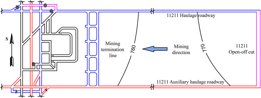
Figure 1. Layout of working face.
As the primary production mine of Yanchang Petroleum, Kekegai Coal Mine extracts the structurally simple and stable Coal Seam No. 2, which averages 4.8 m in thickness with a near-horizontal dip angle (<1°) at mining depths of 478.6–500.1 m. The mine’s inaugural 11211 longwall working face features a strike length of 2,339.7 m and a dip length of 400 m.
To accommodate large-scale mining equipment installation, a large-section open-off cut (11000 mm × 4,800 mm) was constructed in two stages: initial excavation of a 6,000 × 4,800 mm rectangular heading followed by final enlargement. The immediate roof consists of cross-bedded, mudstone-cemented gray-white medium-grained sandstone (25.0 m thick) exhibiting poor stability as a weak-to-semi-hard rock layer prone to instability, while the immediate floor comprises horizontally-bedded sandy mudstone (1.8 m thick). The borehole lithology profile is presented in Figure 2.
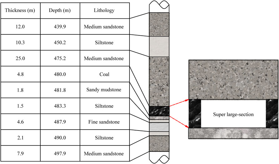
Figure 2. Borehole histogram.
2.2 Stability analysis of surrounding rock
The roof stratum of the 11211 open-off cut consists of mud-cemented sandstone characterized by weak interlayer bonding strength, low shear resistance capacity, and a pronounced tendency for interlayer slippage and delamination. The mud cementation significantly compromises the sandstone roof’s structural integrity, while the exceptionally large 11 m span further exacerbates roof deformation issues through increased bending moments, creating compound stability challenges from both material weakness and structural dimensions. These factors collectively lead to a high-risk stability scenario with heightened potential for progressive failure mechanisms, substantially increasing the difficulties in surrounding rock control.
3 Mechanism of failure in large-section open-off cuts with composite roofs
Following excavation, the surrounding rock undergoes stress redistribution, inducing inward deformation of the rock mass toward the roadway. Tensile stress develops within the composite roof, and when the peak tensile stress exceeds the rock mass’s tensile strength, the overlying strata destabilize and progressively collapse. Consequently, the roadway cross-section transitions from rectangular to arched, with the roof forming a parabolic pressure arch.
As shown in Figure 3, the instability mechanism of large-section open-off cuts with composite roofs can be divided into four characteristic stages (Xuan et al., 2019) based on the pressure arch formation process: 1) Layered Shear. Post-excavation, the composite roof deflects downward under self-weight, while tectonic stress drives inward convergence of the coal ribs. This stress is transferred to adjacent roof strata, inducing interlayer separation due to shear stress. Consequently, the roof’s bending resistance is significantly reduced. 2) Deflection and Delamination. The separated strata experience further deflection under horizontal compression and gravitational forces, exacerbating delamination. Concurrently, tensile stress within the layers accumulates progressively. 3) Tensile Fracture. Once the tensile stress peak attains the material’s tensile strength, the strata undergo fracture and localized collapse. 4) Collapse-Induced Arching. The collapse of lower strata deprives the upper layers of support, causing them to undergo the same failure sequence under gravitational and tectonic stresses until a stable pressure arch is established.

Figure 3. Mechanism of composite roof collapse: (a) Layered Shear; (b) Deflection and Delamination; (c) Tensile Fracture; (d) Collapse-Induced Arching.
The corresponding pressure arch structural model is illustrated in Figure 4.
where b1 is the pressure arch height, λ is the lateral pressure coefficient, a is the half-span of the open-off cut, b is the half-height of the open-off cut, and φ1 signifies the internal friction angle of the rock.
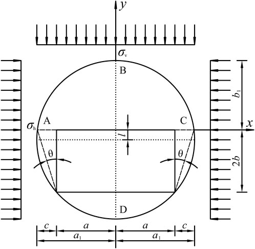
Figure 4. Mechanical model of the pressure arch.
From Equation 1, it can be concluded that the span of the open-off cut is directly proportional to the height of the pressure arch. An increase in span leads to a sharp rise in roof bending moment. The roadway under high stress continuously releases stress and energy, weakening the bonding capacity between the weak interfaces of composite roof strata. This results in deflection, delamination, and even collapse. To address the roof failure mechanism in large-section open-off cuts with composite roofs, a combined support method using bolts, mesh, and cables can be employed. This approach improves stress distribution, mitigates damage to the lower roof strata, ensures roadway surrounding rock stability, and guarantees safe mining operations.
4 Support parameter design for large-section open-off cuts with composite roofs
4.1 Determination of failure zone in roadway surrounding rock
Based on the geological and mining parameters of the 11211 working face, the open-off cut dimensions are defined as half-span a = 5.5 m and half-height b = 2.4 m. Lateral pressure coefficient λ = 1.2, and internal friction angle φ1 = 23° for the muddy cemented sandstone roof. Substituting these values into Equation 1 yields the pressure arch height b1 = 3.79 m for the 11211 open-off cut.
The rib failure depth c is calculated using Equation 2:
In the calculation, the following parameters are adopted: stress concentration factor kσ = 1.8; uniaxial compressive strength of coal σc = 17.4 MPa; average bulk density of overburden γ = 25 kN/m3; burial depth H = 480 m; coal seam dip angle β = 1°; half-span of open-off cut a = 5.5 m; half-height b = 2.4 m; Poisson’s ratio of coal μ = 0.4; and internal friction angle of coal seam φ2 = 21°. Based on these parameters, the calculated failure depth c of the open-off cut rib is determined to be 1.98 m.
where the stress concentration factor kσ = 1.8, the uniaxial compressive strength of coal σc = 17.4 MPa, the average bulk density of overburden γ = 25 kN/m3, the burial depth H = 480 m, the coal seam dip angle β = 1°, the half-span of open-off cut a = 5.5 m, the half-height b = 2.4 m, the Poisson’s ratio of coal μ = 0.4, and the internal friction angle of coal seam φ2 = 21°. Based on these parameters, the calculated failure depth c of the open-off cut rib is determined to be 1.98 m.
4.2 Design of bolt support parameters
The bolt length Lg is calculated using Equation 3:
where the exposed length L1=0.1 m, L2 denotes the effective length, and the anchorage depth L3=0.3 m. For roof bolts, the effective length L2 is calculated using Equation 4, while for rib bolts, L2 corresponds to the rib failure depth c in the open-off cut, as established in previous calculations. This design approach ensures proper load transfer and stability in both the roof and rib support systems.
where the rock mass stability influence coefficient Nr = 1.0 and the collapse span Bm = 11 m for the open-off cut. The calculation results indicate that the minimum required bolt lengths are 2.6 m for the roof and 2.38 m for the ribs of the 11211 open-off cut.
The bolt diameter d is calculated using Equation 5:
where d is the bolt diameter, Q is the anchoring force, taken as 100 kN; and σt is the tensile strength of the bolt material, taken as 335 MPa. The calculation yields a bolt diameter d of 19.4 mm, indicating that bolts with a diameter of 20 mm or larger should be selected for the 11211 open-off cut to meet requirements.
The bolt spacing i is determined by ensuring the anchoring force Q satisfies the equilibrium condition Q ≥ γL2i2, where γL2i2 represents the weight of the suspended rock mass per bolt. The spacing between bolts i is calculated using Equation 6:
where i is the spacing between bolts; Q is the bolt anchorage force, taken as 100 kN; L2 is the effective length of the roof bolts, taken as 2.2 m; Kg is the bolt support safety factor, taken as 1.05; γ is the gravitational density of the suspended roof rock, taken as 25 kN/m3. The calculated results show that the spacing between bolts should not exceed 1.32 m.
4.3 Design of anchor cable support parameter
The anchor cables are designed to transfer the load from unstable rock strata beneath the pressure arch to the more stable overlying rock formations. The cable length Ls is calculated using Equation 7:
where Ls is the total anchor cable length; La is the anchorage length in stable overlying strata; Lb is the thickness of the suspended unstable layer, taken as the pressure arch height of 3.79 m; Lc is the combined thickness of the bearing plate and anchorage device, taken as 0.1 m; and Ld is the exposed tensioning length, taken as 0.3 m.
The required anchorage length La for the anchor cable in the overlying stable rock stratum is calculated using Equation 8:
where Ks is the safety factor for anchor cable support, taken as 2.4; ds is the diameter of the anchor cable, taken as 21.8 mm; fa is the tensile strength of the anchor cable, taken as 1,860 MPa; and fc is the bond strength between the anchor cable and the anchor grout, taken as 15 MPa. The calculation yields the anchorage length La of the anchor cable into the more stable rock layer above as 1.62 m, and the length of the anchor cable should be no less than 5.81 m.
The spacing j between anchor cables is calculated using Equation 9:
where N is the number of anchor cables, taken as 5 or 6; F2 is the ultimate bearing capacity of the anchor cables, taken as 582 kN; B is the span of the open-off cut, taken as 11 m; h is the thickness of the suspended rock, taken as the height of the pressure arch of 3.79 m; γ is the average unit weight of the suspended rock, taken as 25 kN/m3. After calculation, when using 5 anchor cables, the reasonable spacing is 2.79 m; when using 6 anchor cables, the spacing should be set to 3.35 m.
Based on theoretical calculations (Liu and Wei, 2024), the preliminary support parameters for the surrounding rock in the 11211 open-off cut were determined, specifying minimum requirements of 19.4 mm bolt diameter, 2.6 m roof bolt length, and 2.38 m rib bolt length. In practice, standard 22 mm diameter coal mine bolts were employed to meet strength requirements, while considering construction practicality, the final lengths were set at 2.6 m for roof bolts and 2.4 m for rib bolts. The theoretical support parameters and the design support parameters are shown in Table 1.
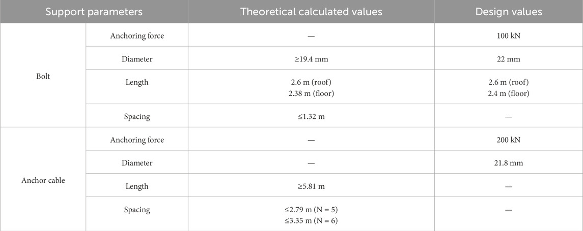
Table 1. Theoretical calculated values and design values of 11211 open-off cut support parameters.
5 Numerical simulation study
5.1 Model establishment
A numerical model was established using Flac3D, with dimensions of 70 m × 70 m × 2.2 m. The dimensions of the 11211 open-off cut sections are 11.0 m × 4.8 m, as shown in Figure 5. The horizontal displacement of the model’s perimeter and the vertical displacement at the bottom were fixed, while a vertical load of 10.7 MPa was applied at the top. The lateral stress influence coefficient was set to 1.2. The rock layers were simulated using the Mohr-Coulomb model, with the mechanical parameters of the model shown in Table 2.
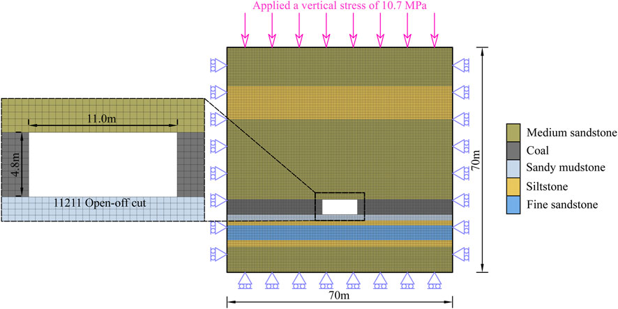
Figure 5. Numerical model.
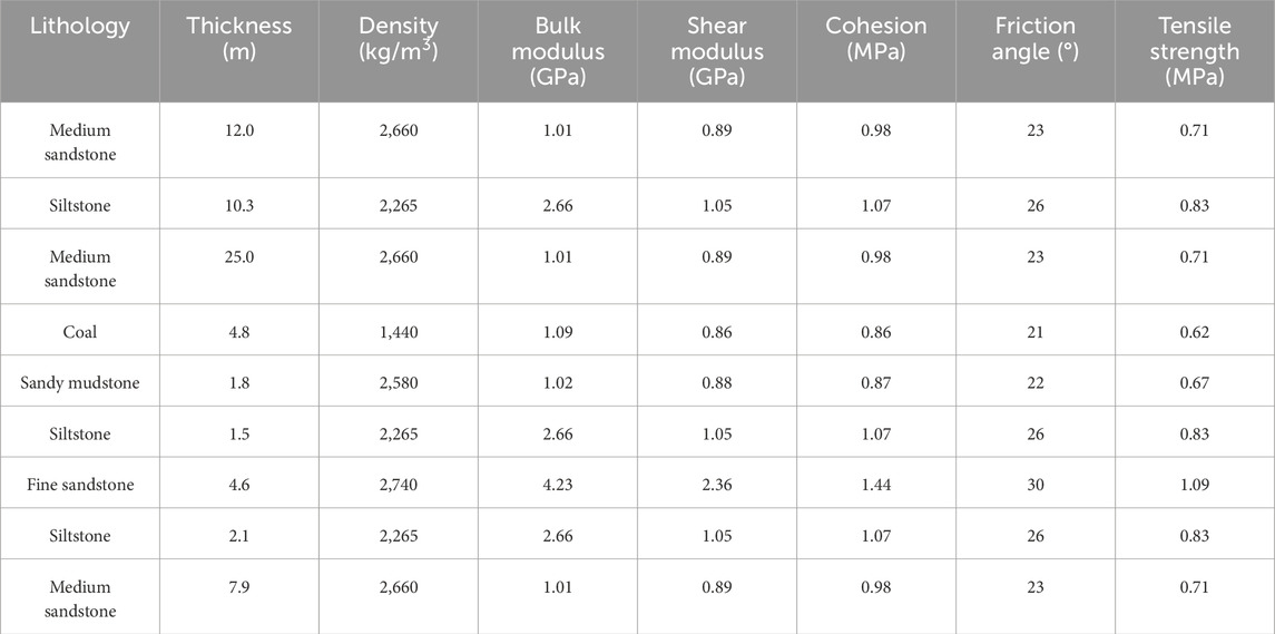
Table 2. Mechanical parameters of the model.
5.2 Influence of open-off cut span on surrounding rock deformation
To investigate the effect of open-off cut span on surrounding rock deformation and mechanical characteristics, numerical simulations were performed for spans of 7 m, 8 m, 9 m, 10 m, and 11 m. The relationships between the open-off cut span and maximum vertical stress, maximum vertical displacement, and plastic zone height in the surrounding rock are presented in Figure 6.
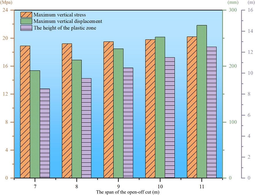
Figure 6. Influence of open-off cut span on surrounding rock deformation.
As shown in the Figure 6, when the open-off cut span increases from 7 m to 11 m, the maximum vertical stress in the surrounding rock increases by 1.3 MPa, representing a 7% increase. The maximum vertical displacement of the open-off cut roof increases by 81 mm, representing a 42% increase. The height of the plastic zone increases by 4 m, representing a 47% increase. In summary, the concentration of rock mass stress, surface displacement, and the size of the plastic zone are directly proportional to the open-off cut span, increasing with the increase in open-off cut span. Among these, the open-off cut span has a relatively minor influence on the concentration of rock mass stress but a significant influence on surface displacement and the development of the plastic zone. For open-off cuts with a span greater than 10 m, the difficulty of control increases significantly compared to ordinary open-off cuts.
5.3 Numerical simulation of support parameters
To gain a deeper understanding of the relationship between the support structure and the surrounding rock, based on the model of the open-off cut with a span of 11 m described above, numerical simulations were conducted using the cable structural element design scheme built into the FLAC3D software. The effects of original rock stress and mining-induced stress were not considered in this study, and the relationship between the support structure and the surrounding rock was investigated.
5.3.1 Numerical simulation of bolt support parameters
To further determine the bolt support parameters for the open-off cut, based on the theoretical calculation results, the bolt length and anchorage force were kept constant. Four bolt test cases were designed according to different spacing and anchor bolt root numbers, as shown in Table 3. In these cases, the bolt lengths for the roof and ribs were set to 2.6 m and 2.4 m, respectively. The preload applied to the bolts was consistent with on-site construction requirements and set to 100 kN. The vertical stress distribution for different bolt support cases is shown in Figure 7, and the horizontal stress distribution is shown in Figure 8.
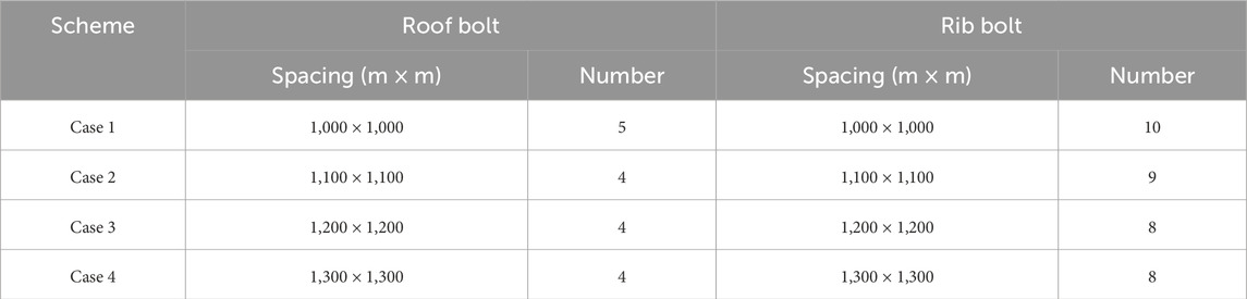
Table 3. Numerical simulation scheme of bolt support parameters.
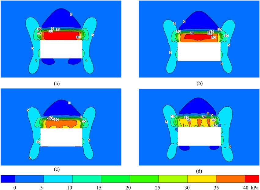
Figure 7. Vertica stress distribution cloud map: (a) case 1; (b) case 2; (c) case 3; (d) case 4.
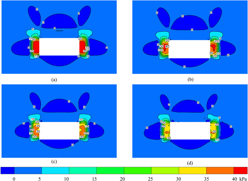
Figure 8. Horizontal stress distribution cloud map: (a) case 1; (b) case 2; (c) case 3; (d) case 4.
As illustrated in Figure 7, the roof bolts’ pre-tensioning force has established a well-defined compressive stress zone within the open-off cut roof while exerting negligible influence on the ribs. In Case 1, a continuous strip-shaped stress concentration zone developed in the roof’s central section, spanning approximately 9 m with a depth of 2 m, exhibiting an average stress exceeding 40 kPa and peaking at 45.35 kPa. Case 2 similarly produced a strip-shaped concentration zone, though with marginally reduced parameters: an 8.5 m span, 2 m depth, average stress above 37.5 kPa, and peak stress of 41.78 kPa. Case 3 demonstrates notably discontinuous stress distribution, lacking the characteristic strip pattern, with dimensions of 8.2 m span and 1.8 m depth, average stress surpassing 35 kPa, and peak stress at 39.66 kPa. Case 4 exhibits three discrete stress concentration zones with limited spatial influence, peaking at 37.16 kPa, where adjacent bolt stress fields remain isolated without forming cohesive overlapping zones. Comparative analysis reveals that Cases 1, 2 generate continuous, high-magnitude compressive stress zones, indicating optimal support performance, whereas Cases 3, 4 produce fragmented, lower-intensity stress distributions, resulting in diminished support efficacy. Consequently, adopting a roof bolt spacing configuration of 1,100 mm × 1,100 mm achieves both operational safety and economic efficiency in open-off cut support.
Figure 8 demonstrates that the rib bolts’ pre-tensioning force creates well-defined compressive stress zones along both sides of the open-off cut while maintaining minimal impact on the roof. Case 1 produces a continuous strip-shaped stress concentration zone in the rib’s central section, extending approximately 3 m vertically and 2 m horizontally, with an average stress above 35 kPa peaking at 45.4 kPa. Case 2 shows reduced dimensions (2.8 m height × 1.8 m depth) while maintaining similar average stress levels, though the peak stress decreases to 42.1 kPa. Case 3 exhibits further discontinuity in the stress pattern, with dimensions of 2.7 m × 1.7 m and a reduced peak stress of 38.2 kPa. Case 4 displays significantly diminished stress concentration, where individual bolts create isolated compressive zones averaging above 30 kPa with a peak of 36.6 kPa. The analysis reveals that only Case 1 achieves continuous, high-magnitude compressive stress distribution, indicating optimal rib support. In contrast, Cases 2–4 demonstrate progressively poorer stress continuity and lower intensity, resulting in reduced support effectiveness. Consequently, a sidewall bolt spacing configuration of 1,000 mm × 1,100 mm is recommended to ensure adequate rib support while maintaining cost efficiency.
5.3.2 Numerical simulation of anchor cable support parameters
Building upon the optimized anchor bolt support parameters, four distinct anchor cable test cases were designed, varying in spacing and length configurations, as detailed in Table 4. The anchor cables were subjected to a preload of 200 kN, consistent with field construction requirements. Figure 8 illustrates the vertical stress distribution across the different anchor cable support cases.
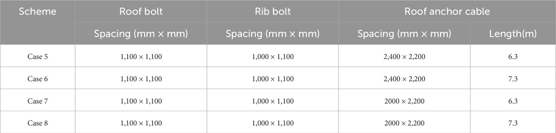
Table 4. Numerical simulation scheme of anchor cable support parameters.
As shown in Figure 9, under the combined action of bolts and anchor cables, a combination and superposition of low-position beam-like load-bearing effects and high-position arch-like load-bearing effects form in the roof rock mass of the open-off cut. In Case 5 and Case 6, the internal compressive stress in the low-level load-bearing beam exceeds 60 kPa, with a peak compressive stress of 80.5 kPa. When the anchor cable length is 6.3 m, the arch height of the high-level load-bearing arch is approximately 5 m, and the internal compressive stress in the arch exceeds 20 kPa. When the anchor cable length is 7.3 m, the arch height of the high-position load-bearing arch is approximately 6.1 m, and the internal compressive stress within the arch exceeds 20 kPa. In Cases 7, 8, the internal compressive stress in the low-position load-bearing beam exceeds 70 kPa, with a peak compressive stress of 82.2 kPa. When the anchor cable length is 6.3 m, the arch height of the high-position load-bearing arch is approximately 4.8 m, and the arch internal pressure stress exceeds 30 kPa. When the anchor cable length is 7.3 m, the arch height of the high-bearing arch is approximately 5.9 m, and the arch internal pressure stress exceeds 30 kPa. From the perspective of anchor cable spacing, it can be seen that the prestressing zones of the 6 anchor cables and the anchor bolts effectively overlap, resulting in better active support performance. From the perspective of anchor cable length, anchor cables with a length of 7.3 m can achieve a larger control range without significantly compromising support strength. Consequently, the anchor cable spacing is set to 2000 mm × 2,200 mm, and the anchor cable length is set to 7.3 m.
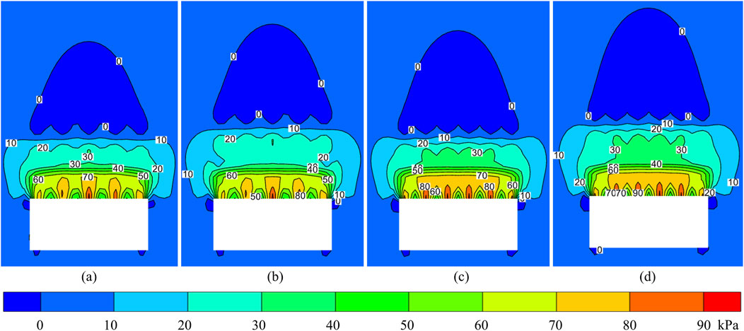
Figure 9. Vertical stress distribution cloud map: (a) case 5; (b) case 6; (c) case 7; (d) case 8.
6 Industrial testing
6.1 Support scheme
Based on theoretical calculations and numerical simulations, the support scheme for the 11211 working face open-off cut was designed, as illustrated in Figure 10. The roof support consists of left-handed threaded steel bolts (ϕ22 mm × 2,600 mm) paired with butterfly-shaped steel plates (ϕ170 mm × 10 mm), arranged in a grid pattern at 1,100 mm × 1,100 mm spacing. For enhanced roof reinforcement, low-relaxation prestressed steel strand anchor cables (21.8 mm × 7,300 mm) were employed, along with 300 mm × 300 mm × 16 mm butterfly-shaped steel plates, spaced at 2,000 mm × 2,200 mm, and integrated with W-shaped steel bands and reinforcing mesh. The coal pillar support utilizes ribbed left-handed threaded steel bolts (ϕ22 mm × 2,400 mm) without longitudinal ribs, combined with ϕ170 mm × 10 mm butterfly-shaped steel plates at 1,000 mm × 1,100 mm spacing, supported by wire mesh. For the mining rib, fiberglass-reinforced plastic bolts (ϕ25 mm × 2,400 mm) were selected, fitted with 150 mm × 10 mm plastic plates and wooden pads, spaced at 1,000 mm × 1,100 mm, and reinforced with plastic mesh. To further enhance roof stability, an additional row of cable bolts (21.8 mm × 7,300 mm) with 2,200 mm spacing was installed in the central roof section, complemented by an array of single hydraulic props working in synergy with metal-hinged roof beams. This comprehensive support system ensures structural integrity and safety during mining operations.
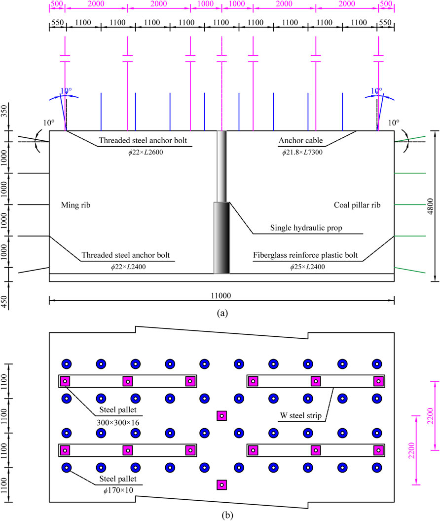
Figure 10. Combined support scheme in the open-off cut (unit: mm). (a) Supported section. (b) Roof support.
6.2 Support effect analysis
After the support for the 11211 open-off cut was completed, monitoring stations were set up. Using the cross-section method, the surface displacement of the surrounding rock was monitored within 30 days after the open-off cut was excavated. Based on the monitoring data, the support plan was optimized in a timely manner. The surface displacement curve of the surrounding rock is shown in Figure 11. Monitoring data showed that the first 22 days after the coal pillar was excavated were a rapid deformation stage, followed by stabilization, with a maximum displacement of 20 mm; the first 21 days after the mining rib was excavated were a rapid deformation stage, followed by stabilization, with a maximum displacement of 24 mm; the first 22 days after the floor was excavated were a rapid deformation stage, followed by stabilization, with a maximum displacement of 33 mm; and the roof experienced a rapid deformation phase for the first 23 days, followed by stabilization, with a maximum displacement of 37 mm. Rock mass deformation was effectively controlled. The open-off cut demonstrated excellent structural stability, with the roof maintaining complete integrity, the floor exhibiting no signs of heaving, and the sidewalls showing negligible deformation. All installed support components performed as designed, remaining fully intact throughout the monitoring period, thereby validating the effectiveness of the support system in maintaining excavation stability under operational conditions.
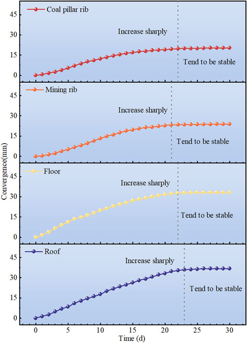
Figure 11. Surface displacement of the open-off cut.
7 Conclusion
This study examines rock mass support strategies for the 11211 open-off cut in Kekegai Coal Mine, focusing on control technologies for composite roof conditions. The key findings are:
(1) Based on engineering geological analysis, this study reveals the deformation and failure mechanism of composite roofs. Composite roofs exhibit low strength and weak interlayer bonding, making them prone to deflection, bending, and failure under self-weight, overburden pressure, and tectonic stresses. For large-section open-off cuts with such geological conditions, a combined support system is essential to optimize stress distribution, minimize lower rock layer failure, maintain surrounding rock stability, and ensure safe mining operations.
(2) Utilizing pressure arch theory, we determined the failure zone dimensions: 3.79 m roof failure height and 1.98 m rib failure depth. Theoretical calculations established appropriate parameter ranges for bolt and anchor cable support systems.
(3) Using FLAC3D numerical simulation software, we systematically analyzed the relationship between open-off cut span and surrounding rock response characteristics. The results demonstrated a significant positive correlation between roadway span and three key parameters: maximum stress value, surface displacement, and plastic zone height. Through comparative analysis of eight support cases and evaluation based on prestress distribution characteristics, we ultimately determined the optimal parameter combination for bolt-cable support.
(4) Based on integrated theoretical calculations and numerical simulations, a bolt-cable combined support system was developed for large-section open-off cuts (11 m span) with composite roofs. Field monitoring data demonstrated excellent performance metrics: the system maintained roof-to-floor convergence below 70 mm and rib-to-rib convergence under 44 mm. These empirical results not only validated the theoretical and numerical predictions, but also proved the system’s effectiveness in maintaining surrounding rock integrity and controlling deformation.
Data availability statement
The original contributions presented in the study are included in the article/supplementary material, further inquiries can be directed to the corresponding author.
Author contributions
SX: Writing – original draft. QZ: Writing – review and editing, Visualization. KW: Writing – review and editing, Supervision.
Funding
The author(s) declare that financial support was received for the research and/or publication of this article. This research was financially supported by Key projects of the Joint Fund of the National Natural Science Foundation of China (No. U21A20107).
Conflict of interest
Author SX was employed by Shaanxi Yanchang Petroleum Yulin Kekegai Coal Industry Limited.
The remaining authors declare that the research was conducted in the absence of any commercial or financial relationships that could be construed as a potential conflict of interest.
Generative AI statement
The author(s) declare that no Generative AI was used in the creation of this manuscript.
Publisher’s note
All claims expressed in this article are solely those of the authors and do not necessarily represent those of their affiliated organizations, or those of the publisher, the editors and the reviewers. Any product that may be evaluated in this article, or claim that may be made by its manufacturer, is not guaranteed or endorsed by the publisher.
References
Cao, Y. X., Zhang, J. P., Yang, T., Chu, H. B., Zhang, X., and Zhang, T. (2023). Mechanism and application of prestressed yielding support for large-span roadway in multistress concentration areas. Processes 11, 1600. doi:10.3390/pr11061600
Chai, J., Liu, Y. L., Gao, S. G., Yang, J. F., Zhang, D. D., Du, W. G., et al. (2022). Analysis of the top coal stability of the large section open-off cut under the gob in thick seams slicing mining. Sci. Rep. 12, 16620. doi:10.1038/s41598-022-21066-x
Chen, D. C., Wang, X. Y., Wu, S., Zhang, F. T., Fan, Z. Z., Wang, X. D., et al. (2023). Study on stability mechanism and control techniques of surrounding rock in gob-side entry retaining with flexible formwork concrete wall, J. Cent. South Univ, 30, 2966–2982. doi:10.1007/s11771-023-5436-z
Chen, D. C., Wang, X. Y., Zhang, F. T., Bai, J. B., Zhao, X. Q., Li, M. L., et al. (2024). Study on the mechanism of progressive instability of special-shaped coal pillar and the stability control of roadway under the influence of mining. Rock Mech. Rock Eng. 57, 6461–6483. doi:10.1007/s00603-024-03798-6
Chen, L., Gao, S. Y., Miao, B., Yao, N., Zhang, S. Z., and Zhang, W. (2022). Field detection and numerical simulation study on roof asymmetric fracture mechanism of large-span soft rock roadway with discontinuity surface. Geofluids 2022, 1–17. doi:10.1155/2022/8945239
Gao, S. G., Du, W. G., Liu, Y. L., Chai, J., Gao, D. Y., Ma, C. Y., et al. (2023). Reasonable top coal thickness for large cross-section open-off cut in lower-layer mining. Front. Earth Sci. 11, 1301595. doi:10.3389/feart.2023.1301595
Kang, H. P., Gao, F. Q., Xu, G., and Ren, H. W. (2023). Mechanical behaviors of coal measures and ground control technologies for China's deep coal mines - a review. J. ROCK Mech. Geotech. Eng. 15, 37–65. doi:10.1016/j.jrmge.2022.11.004
Kang, H. P., Lin, J., and Fan, M. J. (2015). Investigation on support pattern of a coal mine roadway within soft rocks - a case study. Int. J. Coal Geol. 140, 31–40. doi:10.1016/j.coal.2015.01.003
Li, C., Li, J., Lian, X. Y., Li, Y. E., Xue, Q., and Feng, J. C. (2021). Roof failure mechanism and control technology of large section open-off cut in soft rock strata with thin thickness. Shock Vib. 2021, 5533741. doi:10.1155/2021/5533741
Li, F., Duan, B. Y., Sun, Y. P., He, X. X., Li, Z. Y., and Wang, B. (2024). Quantitative risk assessment model of working positions for roof accidents in coal mine. Saf. Sci. 178, 106628. doi:10.1016/j.ssci.2024.106628
Li, G., Ma, F. S., Guo, J., Zhao, H. J., and Liu, G. (2020). Study on deformation failure mechanism and support technology of deep soft rock roadway. Eng. Geol. 264, 105262. doi:10.1016/j.enggeo.2019.105262
Liu, S. G., Bai, J. B., Wang, X. Y., Wu, B. W., Wang, G. H., Li, Y. H., et al. (2021). Study on dynamic evolution of roof crack and support timing of secondary tunneling for large section open-off cut in deep mines. Adv. Civ. Eng. 2021, 9918470. doi:10.1155/2021/9918470
Liu, X. Q., and Wei, S. R. (2024). Optimization of surrounding rock support parameters for shallow buried thick and hard roof coal seam roadway. China Min. Mag. 33, 312–316+322. doi:10.12075/j.issn.1004-4051.20240620
Pu, L., Liu, Y. J., Cai, Y. B., Sun, Z., and Zhou, X. (2023). Study on active support parameters for surrounding rock with ultra-large span open-off cut in thick coal seam. Appl. Sciences-Basel 13, 12804. doi:10.3390/app132312804
Ranjith, P. G., Zhao, J., Ju, M., De Silva, R. V. S., Rathnaweera, T. D., and Bandara, A. K. M. S. (2017). Opportunities and challenges in deep mining: a brief review. Engineering 3, 546–551. doi:10.1016/J.ENG.2017.04.024
Sun, J., Yang, Y., Zhao, Y. J., Chen, S. Q., and Hu, D. S. (2024). Design of support parameters of large-section open-off cut and its dynamic mining response characteristics. Shock Vib. 2024, 5985318. doi:10.1155/vib/5985318
Wang, X. J., Tang, J. Z., Li, Y. M., and Fu, Q. (2023). The failure law and combined support technology of roadways with weak surrounding rock in deep Wells. Appl. Sciences-Basel 13, 9738. doi:10.3390/app13179738
Xie, H. P., Gao, M. Z., Zhang, R., Peng, G. Y., Wang, W. Y., and Li, A. Q. (2019). Study on the mechanical properties and mechanical response of coal mining at 1000m or deeper. Rock Mech. Rock Eng. 52, 1475–1490. doi:10.1007/s00603-018-1509-y
Xie, S. R., Zhang, Q., Chen, D. D., Wang, E., Zeng, J. C., Ji, C. W., et al. (2020). Research of roof Anchorage rock beam bearing structure model of extra-large width open-off cut and its engineering application in a coal mine, China. Adv. Civ. Eng. 2020, 3093294. doi:10.1155/2020/3093294
Xuan, Z. J., Chang, Q. L., Shi, X. Y., Wang, H., and Li, X. Y. (2019). Mechanism of instability and control technology of deep-buried large-span coal roadway under composite roof. Saf. Coal Mines 50, 170–174. doi:10.13347/j.cnki.mkaq.2019.01.042
Yang, S. Q., Chen, M., Jing, H. W., Chen, K. F., and Meng, B. (2017). A case study on large deformation failure mechanism of deep soft rock roadway in xin'An coal mine, China. Eng. Geol. 217, 89–101. doi:10.1016/j.enggeo.2016.12.012
Zhang, D., Bai, J. B., Tian, Z. J., Zhang, Z. Z., Guo, Y. H., Wang, R., et al. (2024). Stability mechanism and control of the pumpable supports in longwall recovery room. Int. J. Min. Sci. Technol. 34, 957–974. doi:10.1016/j.ijmst.2024.07.006
Keywords: composite roof, large section, open-off cut, pressure arch, bolt and anchor cable support
Citation: Xu S, Zhou Q and Wang K (2025) Surrounding rock control technology of large-section open-off cut with composite roof under deep mining conditions: a case study. Front. Earth Sci. 13:1633751. doi: 10.3389/feart.2025.1633751
Received: 23 May 2025; Accepted: 17 July 2025;
Published: 25 July 2025.
Edited by:
Xin Yin, City University of Hong Kong, Hong Kong SAR, ChinaReviewed by:
Yang Dengfeng, Qingdao University of Technology, ChinaZhen Hao, Henan Institute of Engineering, China
Copyright © 2025 Xu, Zhou and Wang. This is an open-access article distributed under the terms of the Creative Commons Attribution License (CC BY). The use, distribution or reproduction in other forums is permitted, provided the original author(s) and the copyright owner(s) are credited and that the original publication in this journal is cited, in accordance with accepted academic practice. No use, distribution or reproduction is permitted which does not comply with these terms.
*Correspondence: Qingcong Zhou, MTM4MTUzMTY1OTVAMTYzLmNvbQ==