 Mingyue Weng1
 Bin Du
- 1Shanghai Datun Energy Co.,Ltd.,Jiangsu Branch, Xuzhou, Jiangsu, China
- 2School of Mines, China University of Mining and Technology, Xuzhou, Jiangsu, China
- 3School of Energy and Mining, China University of Mining and Technology-Beijing, Beijing, China
Aiming at the problem of poor control over coal wall spalling and roof instability when large-mining-height working faces in deep mines pass through fault fractured zones, this study takes the fault fractured zone in the 7,436 working face of Kongzhuang Coal Mine as the engineering background. Through experimental testing of different grouting materials for material optimization, numerical simulation of grout diffusion laws in the fracture network of fault zones, and industrial trials of advanced grouting reinforcement, the directional regulation mechanism of grouting hole spatial layout parameters on grout seepage in fault fractured zones is revealed. The results show that Jumina ultra-fine cement achieves an optimal balance among rheological properties, mechanical characteristics, and economic efficiency. When grouting holes are vertically positioned within 1.0 m above the coal seam, bidirectional grout diffusion into the coal seam and roof is realized, reducing the risk of grout leakage in the fault zone. When grouting holes horizontally extend more than 2 m beyond the fault, the grout diffusion range expands, with the proportions of grouting volume and seepage length in the fault zone decreasing to 34% and 30%, respectively, achieving the best seepage effect. Orthogonal tests identify a water-cement ratio of 0.6 and a grouting pressure of 15 MPa as the optimal parameter combination. Industrial trials confirm that after implementing the optimized grouting scheme, spalling and roof collapse phenomena are significantly reduced, and the working face advancing rate is increased from 1 cycle every 2 days to 2–3 cycles per day, greatly improving working face production efficiency.
1 Introduction
As coal mining gradually progresses to greater depths, the complexity of geological conditions increases, such as a higher density of working face faults. Coal wall spalling and roof leakage in front of supports in large-mining-height longwall working faces exhibit characteristics of high frequency and strong suddenness, leading to reduced advancing efficiency of fully mechanized mining equipment and even production interruptions (Guo et al., 2024; Wang et al., 2021b; Zhang J. et al., 2023). In the research on surrounding rock stability control methods (Kong et al., 2021; Liu et al., 2021; Xue et al., 2024), grouting reinforcement technology has become a core means for treating deep fractured zones due to its advantage in actively regulating the mechanical properties of fractured coal-rock masses (Cui et al., 2021; Pan et al., 2024).
Grouting modification and reinforcement of fractured surrounding rock mainly involve research on grouting materials, grout diffusion mechanisms, and grouting process optimization (Hu et al., 2022). Grouting materials are primarily classified into inorganic and organic types (Kang et al., 2024). For inorganic grouting materials, scholars have improved their permeability and compressive strength by optimizing particle size grading and adding admixtures (such as accelerators and expanding agents) (Li et al., 2023; Lu et al., 2022; Xiong et al., 2021). For organic grouting materials, physical and chemical modifications have been used to optimize limitations in strength, thermal conductivity, and flame retardancy (Wang et al., 2023; Yu, 2023; Zhang et al., 2025). The study of grout diffusion laws mainly focuses on two categories: diffusion in single fractures and fracture networks. In theoretical research on grout diffusion in single fractures,Hässler et al. (1992) derived grout flow and diffusion equations considering fracture aperture and roughness. El Tani and Stille, 2017 studied grouting processes under different conditions by deriving flow formulas for Newtonian and non-Newtonian fluids in one-dimensional and two-dimensional channels. In numerical simulation research, Zhang H. et al. (2023) established a coupled model for Bingham fluid diffusion-bonding-consolidation, enabling numerical simulation of the full process of grout diffusion and consolidation in single-fracture rock masses. For fracture-network grout diffusion, Moon and Song, (1997) obtained flow and diffusion laws of Bingham fluids in rock fracture networks considering the time-varying viscosity of grout. Eriksson et al. (2000) proposed that fracture apertures at intersection points of fracture grids follow a logarithmic distribution, and grout does not flow in contact areas between fracture surfaces. In experimental studies, Liu et al. (2020a) investigated the effects of grouting parameters on grout diffusion using a self-made multi-fracture grouting model with spliced marble. Zou et al. (2020) designed a fracture-network model to validate theoretical derivations for the diffusion of power-law fluids in fracture grids. In numerical simulations, Liu et al. (2020b) developed a grout diffusion program for fracture networks to shorten the simulation time, while Chen et al. (2024) established a 3D numerical model of fracture networks to achieve quantitative simulation of grout diffusion processes. In research on grouting process optimization, Zheng et al. (2023) optimized grouting angles through numerical simulations of advanced grouting in different directions for submarine tunnels passing through fault fractured zones. Hua et al. (2023) studied grouting reinforcement laws under different circumferential and radial conditions to optimize processes suitable for high groundwater environments. Wang et al. (2021a) clarified the influence of water-cement ratios and reinforcement layer thickness on surrounding rock deformation and adjacent tunnels, optimizing grouting parameters. Zhang et al. (2020) investigated the variation of grout penetration range in surrounding rock and roadway deformation with grouting time to optimize the timing of grouting reinforcement. Yan et al. (2022) optimized long-distance flexible grouting reinforcement schemes by simulating flexible grouting at different positions.
Existing studies on grout diffusion laws in grouting reinforcement are mostly limited to idealized point-source diffusion models, with significant discrepancies remaining between theoretical models and engineering practices. The diffusion laws of grout within the fracture networks of large-scale fault fractured zones are still poorly understood. Based on the actual geological structure of the 7,436 working face in Kongzhuang Coal Mine, this study conducts research on grout diffusion laws under different spatial relationships between large-scale fault fractured zones and grouting holes through laboratory parameter testing of grouting materials and numerical simulations. According to the research results, an advanced grouting reinforcement control technology scheme for working face fault fractured zones is designed, and industrial trials are carried out.
2 Engineering background
The 7,436 working face in Kongzhuang Coal Mine is located at an elevation of −964.3 to −844.5 m, with an average burial depth of 937 m, a strike length of 1,270 m, and a dip length of 229 m, as shown in Figure 1. The average coal seam thickness is 4.15 m, with an average dip angle of 19°. The immediate roof consists of silty mudstone (locally fine sandstone) with an average thickness of 1.43 m; the main roof is medium-grained sandstone with an average thickness of 9.59 m. The immediate floor is silty mudstone with an average thickness of 4.15 m, and the main floor is fine sandstone with an average thickness of 7.8 m. The working face adopts the strike longwall full-seam mining method with full roof caving.
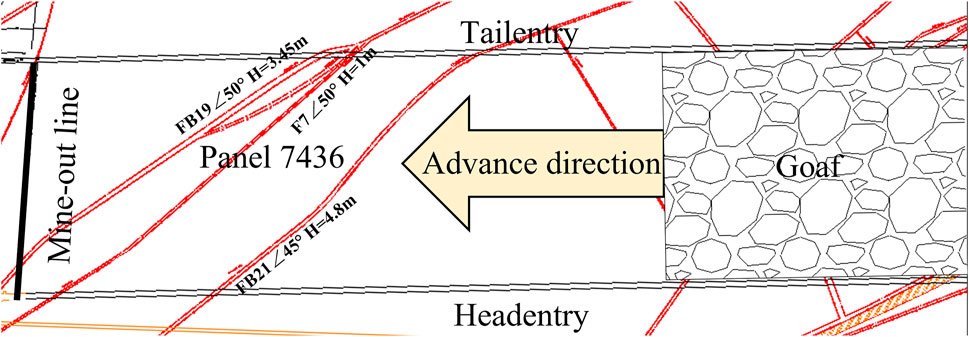
Figure 1. Geological structure map of the working face.
The working face reveals 22 fault structures, with significantly developed surrounding rock fractures in the structural area. The steep dip angle occurrence conditions of the coal seam lead to support skew and insufficient stability of the surrounding rock structure. Water infiltration at locally developed structural positions further weakens the load-bearing capacity of the roof. The coupling of these multi-factors results in frequent coal wall spalling and roof collapse-leakage in the working face. Additionally, the previously conducted advanced grouting projects suffered from issues such as blind design of grouting holes and unreasonable spatial positioning, leading to ineffective grout diffusion and insufficient effective grout injection in target areas. This caused severe grouting material waste and poor treatment effects, failing to meet the required reinforcement rates for roof strata and coal masses. Therefore, it is necessary to redesign the advanced grouting scheme for deep fault fractured zones and optimize the parameters.
3 Materials and methods
3.1 Experimental materials and design
In response to the complex geological conditions and developed faults in the Kongzhuang 7,436 working face, experimental studies on rheological and mechanical properties were conducted to meet the requirements for grouting material selection and parameter determination, providing laboratory-measured parameters for subsequent numerical simulations. The cementitious materials used in this experiment were three types of grouting materials previously applied for reinforcement at Kongzhuang Coal Mine: Jumina ultra-fine cement (JMN), inorganic two-component material (IBC), and organic two-component material (OBC). Portland cement PO42.5 (PC) was selected as the control group for comparative study.
Based on the grout mix ratio applied in the early-stage engineering of the 7,436 working face, the slurry was prepared for this experiment. PC and JMN dry materials were uniformly mixed with water at a water-cement ratio of 0.35 and fully stirred. For IBC, the dry materials of Component A and Component B were proportioned at a mass ratio of 1:1, uniformly mixed, then combined with water at a water-cement ratio of 0.35 and fully stirred. For OBC, the grouts of Component A and Component B were mixed at a volume ratio of 1:1, rapidly and thoroughly stirred to ensure uniform mixing, completing the slurry preparation. The fluid properties of the prepared slurries were characterized through setting time, bleeding rate, and fluidity tests.
Using a round-hole sieve at the 7,436 working face, coal particles and roof rock particles with a particle size of 10–20 mm were screened as preparation materials for the cemented specimens. The four different slurries were uniformly mixed with coal particles and rock particles in molds, respectively, to prepare 100 mm × 100 mm × 100 mm cemented specimens for uniaxial compression tests and 40 mm × 40 mm × 160 mm cemented specimens for flexural strength tests. (The average weight of coal in a single cube mold was 1.00 kg, the average weight of rock was 2.10 kg; the average weight of coal in a single prism mold was 0.25 kg, and the average weight of rock was 0.55 kg) After demolding, the specimens were cured in a YH-40B standard constant-temperature and humidity curing chamber at 20°C ± 2°C and 95% humidity for 7 days, 14 days, 21 days, and 28 days. This compared the bonding performance of different cementitious materials on the fractured coal-rock mass in the Kongzhuang 7,436 working face and the mechanical properties of the cemented bodies under the same curing environment but different curing times. The main experimental procedures are shown in Figure 2.
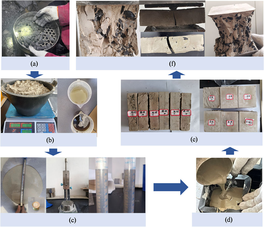
Figure 2. Schematic of the experimental process. (a) Field sampling. (b) Grout mixing. (c) Parameter measurement. (d) Specimen casting. (e) Curing and demolding. (f) Strength test.
3.2 Numerical model construction and simulation scheme
Following laboratory tests to select the most suitable grouting material for Kongzhuang Coal Mine’s 7,436 working face, research was conducted on the grout diffusion mechanism and optimization of grouting process parameters for advanced grouting in the working face’s fault fractured zone. This study established a two-dimensional numerical model using UDEC software based on the discrete element method (DEM). DEM treats the whole medium as a discontinuous system composed of independent sub-entities, characterizing fractured rock masses as a combination of blocks and joints. This approach best reflects the essence of grout fluid diffusion in the fractured rock network space within actual engineering scenarios, enabling intuitive and accurate simulation of macroscopic diffusion paths and distribution differences of grout within the complex fracture networks of fault fractured zones and intact surrounding rock. The flow of mine grouting materials represented by cement-based grouts in coal-rock fractured zones is typically modeled as a non-Newtonian Bingham fluid, characterized by yield shear strength and dynamic viscosity. The grout behaves as a rigid body under low stress and a viscous fluid under high stress. The fluid characteristics were simulated using UDEC software to realize the initiation and flow processes of grout within the fractures. The flow behavior follows a modified Bingham fluid model, with flow rate calculations described by Equations 1, 2:
Where
Where a is the joint aperture,
Based on the geological and mining conditions of the 7,436 working face, a two-dimensional numerical model of the Kongzhuang 7,436 working face was established using UDEC software. The model dimensions are 250 m × 55 m. To reduce model complexity and computational scale, a single key fault (FB19; dip angle 50°, H = 3.5 m) was simulated. Coal pillars of 50 m width were reserved on both lateral boundaries to eliminate boundary effects. To ensure the grout diffusion pattern realistically reflects the discontinuous characteristics of fractured rock masses, the coal seam and roof/floor were discretized using random polygonal meshes. The upper boundary of the model was set as a stress boundary with a vertical stress of 23.6 MPa and a lateral pressure coefficient of 1.5. The bottom boundary was fixed with zero velocity in both the X and Y directions, as shown in Figure 3. The Mohr-Coulomb criterion was employed to simulate the failure process. Model parameters were determined based on the grouting materials used and the characteristics of the complex structural surrounding rock mass, as listed in Table 1. These include a fracture permeability factor of 1 × 10⁸, zero-stress fracture aperture of 0.1 mm (1 mm in the fault zone), and residual fracture aperture of 0.02 mm (Wu et al., 2021). This setup significantly highlights the fault fractured zone as the core preferential seepage pathway for grout, enabling the study of its dominant influence on grout diffusion.
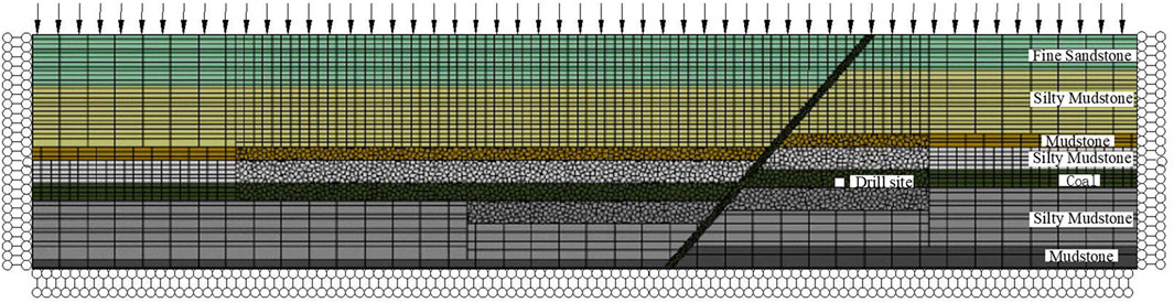
Figure 3. Mechanical model of the working face.
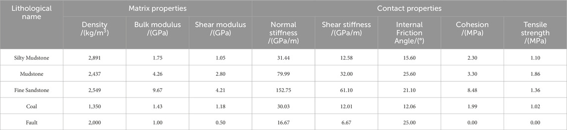
Table 1. Physico-mechanical parameters of coal-rock strata.
The basic assumptions for grout diffusion in the model are as follows:
(1) Joints are in a dry state, with impermeable strata above the joints and impermeable boundaries at the model edges.
(2) Grout is treated as an incompressible Bingham fluid diffusing along the fracture network.
(3) Grout pressure affects fracture width during simulation, and fracture deformation reciprocally influences grout diffusion.
(4) Thermal effects from grout hydration reactions are neglected.
The spatial positioning of grouting holes exerts a significant controlling effect on the reinforcement efficiency of fractured surrounding rock. Two critical dimensions include the strike-space relationship between the final hole position and the fault zone, as well as the vertical space relationship between the hole layout layer and the coal-rock strata. In this study, quantitative analysis was conducted by constructing different numerical models, as listed in Table 2 and shown in Figure 4. All simulation schemes adopted identical and constant grouting pressure, water-cement ratio, and contact parameters. Specifically, the horizontal height and length of grouting holes were unified in the model group with different final hole positions, while the length of grouting holes was unified in the model group with different hole layout layers. Based on laboratory measurements and the actual grouting engineering in the 7,436 working face of Kongzhuang Coal Mine, the grouting pressure was set at 12 MPa, the water-cement ratio of Jumina grout was 0.35:1, and the density was 2000 kg/m3.
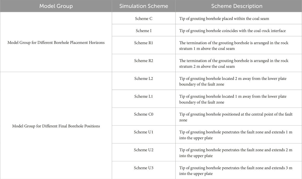
Table 2. Numerical model scheme table.
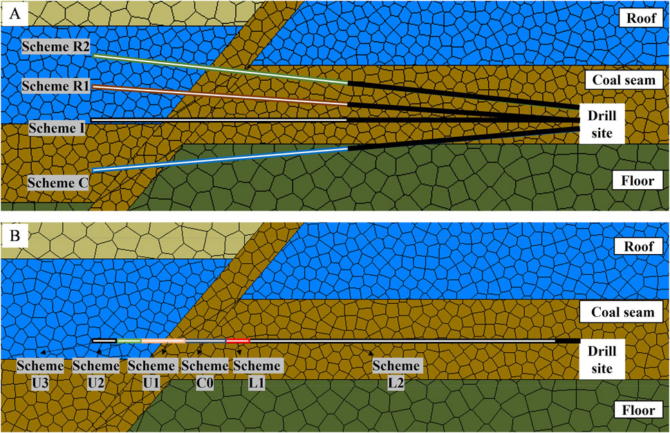
Figure 4. Schematic of advanced grouting numerical simulation schemes. (A) Schematic of simulation schemes for different hole layout layers; (B) Schematic of simulation schemes for different final hole positions.
To optimize the grouting parameters in the advanced grouting reinforcement scheme for the 7,436 working face of Kongzhuang Coal Mine, an orthogonal test was conducted using the numerical simulation results of different schemes to select the most ideal grout diffusion scheme. The orthogonal test was introduced to investigate grout diffusion under different water-cement ratios and grouting pressures, without considering the interactions between factor levels. Representative parameters were selected as the values for each level, and the final orthogonal test design table is presented in Table 3.
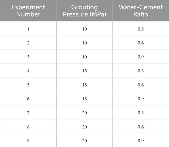
Table 3. Orthogonal experimental design matrix.
In this study, the total grout seepage length (
Where
4 Results and discussion
4.1 Results of fluid-solid property experiments and material selection
4.1.1 Rheological properties
The comparison results of setting time, bleeding rate, and fluidity for cementitious materials are shown in Figure 5. Due to its ultra-fine particle size and high specific surface area, JMN exhibits significantly enhanced hydration reactions, with initial and final setting times shortened to 141 min and 175 min–18.0% and 26.2% lower than those of PC, respectively. Two-component materials show extremely short setting times due to chemical catalysis: the initial setting times of IBC and OBC are 2.3 min and 1.7 min, respectively, but their fluidity decreases, indicating that rapid curing sacrifices grout diffusivity. JMN has a slightly higher bleeding rate than PC due to particle packing effects, while the bleeding rates of IBC and OBC are reduced to 0.21% and 0, respectively, significantly inhibiting grout stratification. Additionally, JMN achieves a fluidity of 264.9 mm, which is 168.1%, 43.5%, and 10.5% higher than that of PC, IBC, and OBC, respectively. Fluidity tests further validate its engineering applicability, indicating both long-distance conveying capacity and high filling efficiency in fractures.
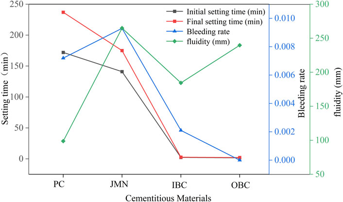
Figure 5. Setting time- Bleeding rate-fluidity comparison curves.
4.1.2 Mechanical properties
After uniaxial compression and flexural tests on fractured coal-rock cemented specimens cured for different days, the results are shown in Figure 6. Here, “-R” denotes fractured rock cemented bodies, and “-C” denotes fractured coal cemented bodies. A comparison of the reinforcement performance of four cementitious materials for fractured coal-rock masses reveals that the mechanical strengths of all cemented bodies exceed 70% of their 28-day strengths after 14 days of curing. JMN exhibits better performance than PC in both uniaxial compressive strength and flexural strength: the 14-day uniaxial compressive strengths of JMN-R and JMN-C are 12% and 24% higher than those of PC-R and PC-C, respectively, with flexural strengths 8% and 0% higher, respectively. The 21-day uniaxial flexural strength of IBC-R and IBC-C are 58% and 12% lower than those of JMN-R and JMN-C, respectively. Although IBC has high compressive strength, its low flexural strength and excessively high compressive-to-flexural strength ratio indicate high brittleness, which may lead to brittle failure under bending stress and affect reinforcement effectiveness. OBC-R and OBC-C show excellent compressive and flexural strengths, but their huge grout consumption for reinforcing fault fractured zones poses serious environmental and economic issues.
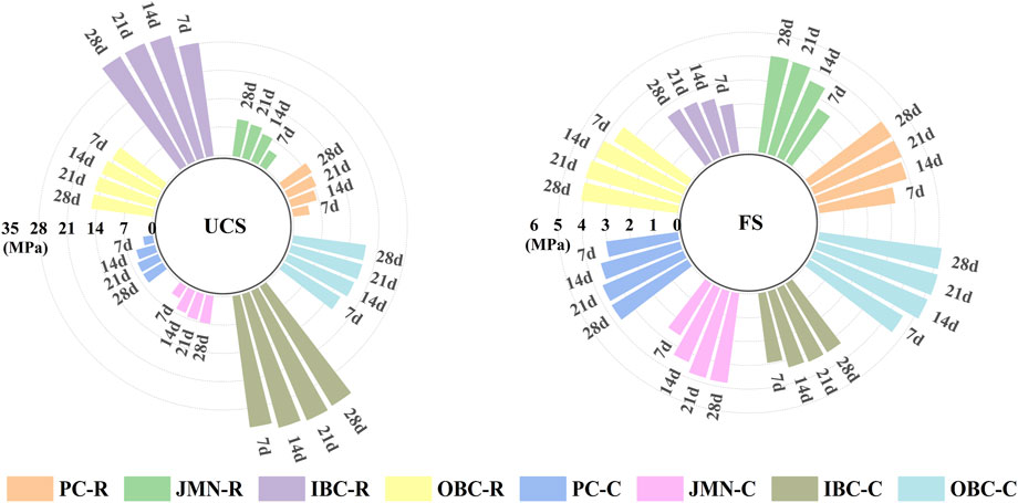
Figure 6. Mechanical properties of fractured coal and rock cemented bodies.
4.1.3 Material selection
In summary, JMN achieves a better balance between compressive and flexural properties while offering better economy and environmental friendliness, making it the optimal choice for advanced grouting reinforcement in Kongzhuang Coal Mine’s 7,436 working face.
4.2 Directional control mechanisms of grout diffusion by spatial positioning of grouting holes
4.2.1 Constraint effect of hole layout layers on seepage paths
Numerical simulation results indicate that the hole layout layers of grouting holes significantly control grout diffusion paths and reinforcement ranges, as shown in Figure 7. When the final hole is located 2 m above the coal seam in the rock stratum (Scheme R2), grout preferentially diffuses along the fracture network of the roof rock mass, leaving un-reinforced blind zones in the coal wall and lower part of the fault fractured zone. Although this scheme forms a strengthened zone in the roof, it provides only very limited reinforcement in the upper coal seam, failing to effectively reinforce the coal mass. When the final hole penetrates into the coal seam (Scheme C), grout tends to flow into the underlying floor due to gravity and borehole inclination, resulting in effective reinforcement of the coal wall but no effective reinforcement of the roof. When the final hole is located at the coal-rock interface (Scheme I) or 1 m above the coal seam in the rock stratum (Scheme R1), the pressure field distributes uniformly on both sides of the coal-rock interface, and grout exhibits bidirectional diffusion: upward diffusion along rock fractures reaches 1.5–2.0 m, while downward diffusion forms a reinforcement circle with a radius of 1.0–1.5 m in the coal mass. Schemes I and R1 show significantly better prevention of roof fracturing than Scheme C and better coal wall reinforcement than Scheme R2, achieving collaborative reinforcement of the upper coal wall and lower roof rock to effectively compensate for the continuous failure of the fault fractured zone.
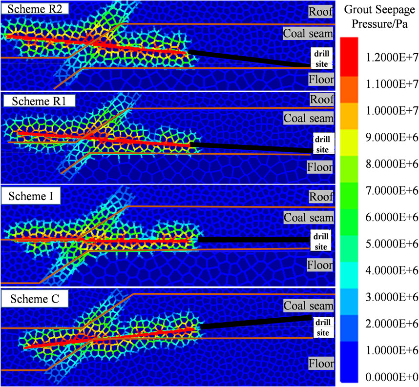
Figure 7. Pressure distribution of grout in different borehole layer positions.
The grout diffusion curves for different hole layout layers are shown in Figure 8. In terms of total seepage length, Scheme R2 has the highest value, Scheme I the lowest, with Schemes R1 and C in between, indicating that seepage ranges for holes ending in rock strata (Scheme R1, Scheme R2) are generally better than those ending in coal seams or at the interface. When holes are arranged at the coal-rock interface (Scheme I), both the proportion of seepage length and grouting volume in the fault zone are the highest among the four Schemes, indicating that grout easily diffuses rapidly into the fault zone along primary fractures at the interface, leading to more obvious ineffective diffusion and a higher risk of grout leakage into the fractured zone. Scheme R1 has the lowest proportions of seepage length and grouting volume in the fault zone, with a slightly higher relative grouting volume than Schemes C and I. This indicates that Scheme R1 can effectively avoid grout leakage into the fault fractured zone while better reinforcing the coal wall and roof. In summary, vertical positioning of the final hole within 1.0 m above the coal-rock interface achieves balanced collaborative reinforcement of coal and roof, improves effective grouting efficiency, and reduces the risk of grout leakage into fault fractured zones.
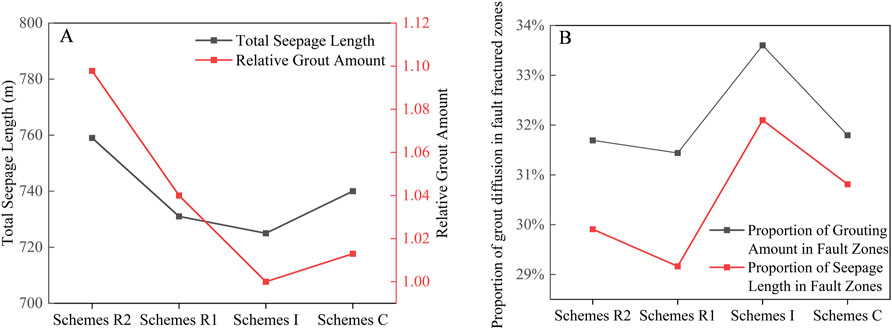
Figure 8. Grout diffusion patterns under different borehole layer positions. (A) Effect of Grouting Hole Layout Levels on Total Seepage Length and Relative Grouting Volume; (B) Proportion Characteristics of Grout Diffusion in Fault Fracture Zones.
4.2.2 Influence of final hole position on seepage channels
As shown in Figure 9, grout diffusion patterns under different final hole positions exhibit significant differential characteristics. When the final hole is located outside the boundary of the fault footwall (Schemes L1–L2), grout diffuses radially only within the rock mass and fails to penetrate into the fault fractured zone, indicating that effective reinforcement of the fractured zone is difficult to achieve when the final hole does not traverse the fault zone. Scheme L2 demonstrates that insufficient sealing segment length leads to grout leakage along mining-induced fractures around the drilling field, reducing grouting efficiency. In Scheme C0, where the final hole is positioned at the center of the fault fractured zone, grout diffuses bidirectionally with the fault zone as the axis, forming a symmetrical reinforcement pattern. However, influenced by the permeable heterogeneity of the fractured zone rock mass, diffusion efficiency toward the hanging wall and footwall is constrained, resulting in significant grout loss. When the final hole penetrates the fault zone and extends to the outside of the hanging wall (Schemes U1–U3), grout forms composite diffusion channels within the fault fractured zone and in the hanging wall/footwall areas, with the diffusion pattern transforming into a radiation-ribbon distribution. Notably, when the final hole extends beyond the critical distance outside the hanging wall (e.g., Schemes U2–U3), part of the grouting pressure gradient transfers to the coal-rock mass outside the hanging wall. This not only forms a composite reinforcement structure in the working face crossing the fault zone—combining a circular diffusion domain (covering both the hanging wall and footwall) and a ribbon-shaped reinforcement zone (penetrating the fractured zone)—but also reduces grout loss intensity in the fault area.
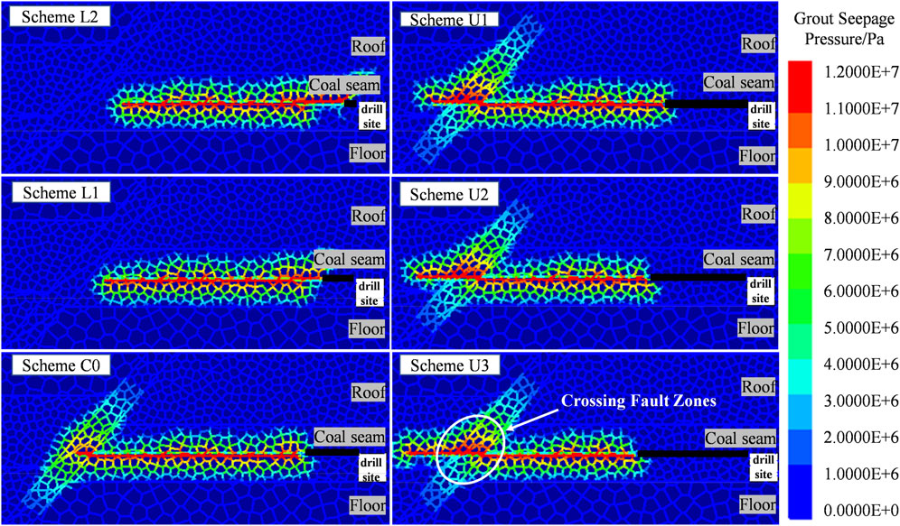
Figure 9. Pressure distribution of grout in different final hole positions.
Figure 10 illustrates the regular variation of grout diffusion parameters with different final hole positions. Figure 10A shows that the grouting volume per unit length in Scheme L2 is significantly higher than in Scheme L1, due to insufficient sealing segment length in Scheme L2 causing grout to preferentially leak along low-resistance mining-induced fractures, forming abnormally extended seepage paths under the same grouting volume. The grouting volume in Scheme C0 reaches 163.4% of that in Scheme L1, reflecting grout loss induced by the highly permeable fractured rock in the fault zone. When the final hole penetrates the fault zone and extends to the hanging wall (Schemes U1-U3), grout preferentially diffuses through the main fracture network of the fault zone toward high-permeability areas, forming dominant seepage channels. Data in Figure 10B show that when the final hole extends 1 m outside the hanging wall (Scheme U1), the proportions of grouting volume and seepage length in the fault fractured zone reach peak values (35.7%, 33.0%), indicating residual grout loss risk in the fault zone. In Scheme U2, with only a 3.5% reduction in grouting volume, the total seepage length remains at 686 m, while the proportions of grouting volume and seepage length in the fault fractured zone decrease. This demonstrates that Scheme U2 effectively reinforces the fault zone while promoting grout diffusion into surrounding rock to form a wide-area reinforcement network, achieving an optimal balance between grouting efficiency and reinforcement range.
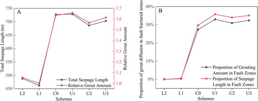
Figure 10. Grout diffusion characteristics at distinct terminal borehole positions. (A) Variation curves of total seepage length and relative grouting volume with terminal hole positions; (B) Proportion Characteristics of Grout Diffusion in Fault Fracture Zones.
4.2.3 Analysis of influences of grouting parameters on grout diffusion efficiency
Based on the above analysis, when the final hole position of grouting holes extends 2 m beyond the fault zone and is located within 1 m above the coal-rock interface, the optimal diffusion effect can be achieved. Therefore, Scheme U2 was selected for numerical simulation analysis to obtain the total seepage length (L), relative grouting volume (Qr), and relative unit grouting efficiency (ηr) under different water-cement ratios and grouting pressures, as shown in Table 4.
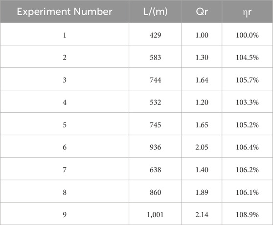
Table 4. Orthogonal test result table.
Experimental results show that as grouting pressure increases or the water-cement ratio increases, both the total seepage length and relative grouting volume exhibit a monotonically increasing trend. For the index of total seepage length, the range of the water-cement ratio (ΔL = 360 m) is 45.6% higher than that of grouting pressure (ΔL = 247 m), indicating that the water-cement ratio is the dominant sensitive factor. When grouting pressure increases from 10 MPa to 20 MPa, increasing the water-cement ratio from 0.3 to 0.9 leads to diffusion range increases of 73.43%, 75.94%, and 56.90% respectively, showing a trend of first increasing and then decreasing. When grouting pressure rises from 10 MPa to 15 MPa, the diffusion increment per unit pressure increase is the largest. At a grouting pressure of 20 MPa, pressure begins to dominate diffusion, causing grout to easily flow away along a single channel and form ineffective diffusion. A grouting pressure of 15 MPa achieves the optimal balance for the diffusion range, avoiding grout retention at low pressure or excessive fracturing at high pressure.
For the relative unit grouting efficiency index, the trend is first an increase followed by stabilization. At a grouting pressure of 10 MPa, increasing the water-cement ratio from 0.3 to 0.9 only improves unit grouting efficiency by 5.7%, indicating limited gains in grouting efficiency from increasing the water-cement ratio under low pressure. When pressure increases to 15 MPa, the unit grouting efficiency reaches 1.052 at a water-cement ratio of 0.6, achieving a better balance between diffusion range and grouting volume compared to ratios of 0.3 and 0.9 under the same pressure. Further increasing pressure to 20 MPa slightly improves unit grouting efficiency, but excessively high pressure in practical engineering may risk fracturing the surrounding rock. Considering both diffusion effect and grouting efficiency comprehensively, the optimal parameter combination is a water-cement ratio of 0.6 and a grouting pressure of 15 MPa.
4.3 Variation characteristics of coal wall stability before and after grouting
Based on the mechanical properties of Jumina-cemented fractured coal-rock masses, modified reinforcement was implemented for the fault fractured zone. A comparative study was conducted by simulating two coal seam excavation scenarios—with and without reinforcement—to investigate the positive impacts of reinforcement on coal mining. When the working face advanced to the critical area 10 m from the fault fractured zone, three indicators were monitored within the 5 m range ahead of the coal wall: the number of shear cracks, the number of tensile cracks, and the maximum horizontal displacement of the coal wall. Comparative analyses were performed before and after grouting reinforcement, as shown in Figure 11. The research results show that in terms of the number of shear fractures, 39 shear fractures developed in this range without grouting reinforcement measures; after grouting reinforcement, the number of shear fractures was reduced to 23, a decrease of 41.0% compared with that before reinforcement. In terms of the number of tensile fractures, after grouting reinforcement, the number of tensile fractures was reduced from 70 to 33, a decrease of 52.9%. In terms of the maximum horizontal displacement of the coal wall, after grouting reinforcement, the maximum horizontal displacement was reduced from 63 cm to 35 cm, a decrease of 44.4% compared with that before reinforcement. Therefore, the grouting reinforcement technology for the fault fractured zone significantly reduced the complexity of the crack network ahead of the coal wall and the horizontal displacement of the coal wall by improving the integrity of the fault fractured zone, thus effectively enhancing the load-bearing performance of the coal wall and reducing geological hazards such as coal wall spalling and roof collapse.
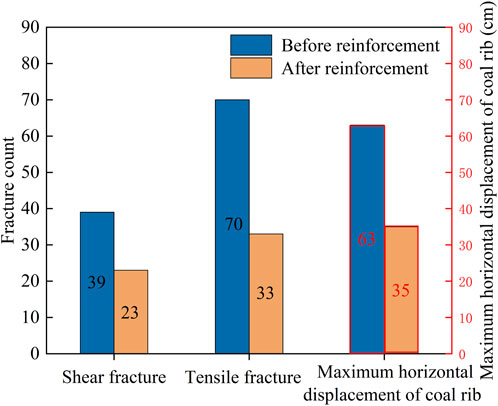
Figure 11. Comparison of coal wall fractures and displacement responses in fault-affected zones before and after reinforcement.
5 Industrial application and validation
5.1 Surrounding rock control scheme
Based on experimental and simulation studies, the optimized grouting reinforcement scheme includes: using Jumina cementitious material to enhance long-distance conveying capacity, fracture filling efficiency, and cementation strength; extending the final hole 2 m beyond the fault zone in the strike direction to reduce grout leakage rate and expand grout diffusion; positioning the final hole vertically within 1 m above the coal-rock interface to achieve bidirectional grout diffusion in coal and rock, cover the working face crossing the fault zone, and reduce floor seepage; adopting graded pressure design with a water-cement ratio not exceeding 0.6, increasing grouting pressure from 12 MPa to 15 MPa during the high-pressure diffusion stage to improve unit grouting efficiency; and extending the sealing segment of grouting holes to reduce grout loss and pressure dissipation along mining-induced fractures.
Considering the geological conditions and on-site construction environment, the advanced grouting drill field for the 7,436 working face is determined to be 37.4 m ahead of Point S13 in the material roadway. Grouting holes are arranged in a fan shape toward the open-off cut, with a total of 22 drill holes, including 13 reserved holes. Long and short holes form a group, with the long hole approximately 15 m longer than the short hole and the same azimuth. Borehole angles range from 9° to 16°, hole depths from 110 m to 170 m, final hole positions within 1 m above the coal-rock interface, and hole spacing no greater than 15 m. The grouting material is Jumina ultra-fine high-permeability single-component grouting reinforcement material, with a grouting pressure of 12–16 MPa. Curtain grouting is applied to the coal wall in the material roadway to prevent grout loss. Within the structural fractured zone, the hole spacing is reduced from 15 m to 10 m for key grouting, as shown in Figure 12.
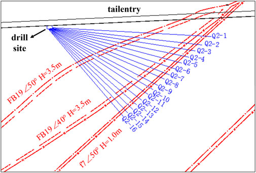
Figure 12. Layout plan for boreholes in the advanced treatment drilling station at the 7,436 working face.
5.2 On-site implementation effect
Six inspection holes were arranged within 30 m ahead of the working face in the 7,436 material roadway to evaluate the grouting effect. The boreholes have a depth of 10 m, with final hole positions within 2 m above the roof. Solidified grout filling was found in most fractures of the fractured rock and coal seam regions, as shown in Figure 13A. After implementing the surrounding rock control scheme, the integrity of the coal wall was significantly improved. The control effects are demonstrated in Figures 13B,C, with fracture reinforcement effects meeting expectations.
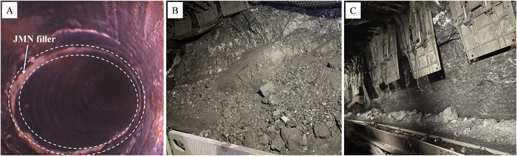
Figure 13. Grouting treatment effect diagram. (A) Borehole view after grouting; (B) Coal wall spalling before grouting reinforcement; (C) Effect diagram after grouting reinforcement.
Figure 14 shows the statistical results of coal wall spalling areas in the working face. It can be observed that after treatment, the occurrence range of coal wall spalling has decreased from the original 20#–120# support interval to 42#–78#, transitioning from long-distance continuous spalling to short-distance sporadic spalling. The quantity and scope of coal wall spalling have significantly reduced, enhancing the supporting effect on the roof and nearly eliminating roof leakage. The face advancing rate has increased from 1 cycle every 2 days to 2–3 cycles per day, forming a virtuous cycle.
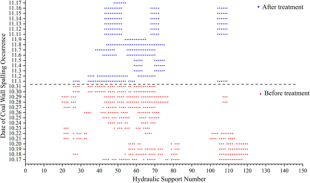
Figure 14. Distribution map of coal wall spalling areas.
6 Conclusion
(1) Compared with PC, IBC, and OBC, JMN shortens initial/final setting times while maintaining high fluidity. Its fractured coal-rock cemented bodies exhibit higher flexural strength while ensuring adequate compressive strength. JMN is suitable as an efficient grouting reinforcement material for deep fault fractured zones.
(2) The optimal seepage effect occurs when grouting holes are vertically positioned within 1.0 m above the coal-rock interface. Grout achieves bidirectional diffusion into the upper coal seam and roof, minimizing the proportion of ineffective seepage in the fault zone and reducing the risk of grout leakage to the greatest extent.
(3) The best seepage performance is achieved when grouting holes horizontally extend 2 m through the fault fractured zone. The grout seepage pattern transforms into a composite structure of radial and strip reinforcement, increasing the seepage length per unit grouting volume and minimizing the risk of grout leakage to the maximum degree.
(4) Orthogonal tests indicate that a water-cement ratio of 0.6 combined with a grouting pressure of 15 MPa represents the most reasonable parameter combination, significantly reducing the number of coal wall fractures after reinforcement. Industrial trials of the optimized grouting scheme show notable reductions in coal wall spalling and roof fracturing, with the working face advancing rate increased to 2–3 cycles per day, demonstrating remarkable governance achievements.
Data availability statement
The original contributions presented in the study are included in the article/supplementary material, further inquiries can be directed to the corresponding author.
Author contributions
MW: Conceptualization, Funding acquisition, Project administration, Writing – original draft, Methodology, Investigation. BD: Data curation, Writing – original draft, Formal Analysis, Software. YZ: Writing – review and editing, Methodology, Project administration. LZ: Resources, Writing – original draft, Investigation. ZW: Writing – original draft, Methodology, Project administration. BF: Writing – original draft, Formal Analysis, Validation. HG: Investigation, Writing – original draft.
Funding
The author(s) declare that financial support was received for the research and/or publication of this article. This research was financially supported by the China National Coal Group Top Talent Recruitment Science and Technology Project (No. GH20230135).
Conflict of interest
Authors MW, LZ, and HG were employed by Shanghai Datun Energy Co.,Ltd.,Jiangsu Branch.
The remaining authors declare that the research was conducted in the absence of any commercial or financial relationships that could be construed as a potential conflict of interest.
Generative AI statement
The author(s) declare that no Generative AI was used in the creation of this manuscript.
Publisher’s note
All claims expressed in this article are solely those of the authors and do not necessarily represent those of their affiliated organizations, or those of the publisher, the editors and the reviewers. Any product that may be evaluated in this article, or claim that may be made by its manufacturer, is not guaranteed or endorsed by the publisher.
References
Chen, Y., Sun, D., Shao, Y., and Ma, G. (2024). A model of cement grout flow in a fracture network system. Comput. Geotech. 175, 106698. doi:10.1016/j.compgeo.2024.106698
Cui, F., Zhang, T., and Cheng, X. (2021). Research on control of rib spalling disaster in the three-soft coal seam. Shock Vib. 2021 (1), 2404218. doi:10.1155/2021/2404218
El Tani, M., and Stille, H. (2017). Grout spread and injection period of silica solution and cement mix in rock fractures. Rock Mech. Rock Eng. 50, 2365–2380. doi:10.1007/s00603-017-1237-8
Eriksson, M., Stille, H., and Andersson, J. (2000). Numerical calculations for prediction of grout spread with account for filtration and varying aperture. Tunn. Undergr. Space Technol. 15 (4), 353–364. doi:10.1016/S0886-7798(01)00004-9
Guo, W., Wang, G., Li, Y., and Chen, D. (2024). Research on coal wall failure and stability control technology of large coal seams with a soft and thick seam. Energy Sci. Eng. 12 (9), 3599–3613. doi:10.1002/ese3.1848
Hässler, L., Håkansson, U., and Stille, H. (1992). Computer-simulated flow of grouts in jointed rock. Tunn. Undergr. Space Technol. 7 (4), 441–446. doi:10.1016/0886-7798(92)90074-R
Hu, S., Liu, Q., and Li, S. (2022). Advance and review on grouting critical problems in fractured rock mass. Int. J. Coal. Sci. Technol. 50 (01), 112–126. doi:10.3969/j.issn.0253-2336.2022.1.mtkxjs202201010
Hua, T., Liu, S., Zhang, X., Meng, L., and Wang, P. (2023). Numerical analysis of grouting of water-enriched karst highway tunnel based on critical water-enriched height. Processes 11, 149. doi:10.3390/pr11010149
Kang, H., Yang, J., Jiang, P., Gao, F., Li, W., Li, J., et al. (2024). Theory, technology and application of grouted bolting in soft rock roadways of deep coal mines. Int. J. Min. Met. Mater. 31 (7), 1463–1479. doi:10.1007/s12613-024-2906-8
Kong, D., Li, Q., Wu, G., and Song, G. (2021). Characteristics and control technology of face-end roof leaks subjected to repeated mining in close-distance coal seams. Bull. Eng. Geol. Environ. 80 (11), 8363–8383. doi:10.1007/s10064-021-02438-5
Li, T., Yue, Z., Li, J., Li, Q., Li, Y., and Chen, G. (2023). Experimental study of improved cement silicate grouting material for broken surrounding rock. J. Build. Eng. 74, 106782. doi:10.1016/j.jobe.2023.106782
Liu, B., Sang, H., Kang, H., Liu, Q., Luo, C., and Zhao, C. (2020a). Development of grouting simulation test system for rock mass fracture network and its application. Chin. J. Rock Mech. Eng. 39 (03), 540–549. doi:10.13722/j.cnki.jrme.2019.0998
Liu, B., Sang, H., Liu, Q., Kang, Y., Pan, Y., Lu, C., et al. (2020b). New algorithm for simulating grout diffusion and migration in fractured rock masses. Int. J. Geomech. 20 (3), 4019188. doi:10.1061/(ASCE)GM.1943-5622.0001537
Liu, S., Yang, K., and Tang, C. (2021). Mechanism and integrated control of “rib spalling: roof collapse—support instability” hazard chains in steeply dipping soft coal seams. Adv. Mater. Sci. Eng. 2021 (1), 5524591. doi:10.1155/2021/5524591
Lu, H., Zhang, K., Yi, J., and Wei, A. (2022). Study on mechanical properties of polycaprolactone modified cement-based material. Int. J. Concr. Struct. Mater. 16 (1), 24. doi:10.1186/s40069-022-00516-w
Moon, H. K., and Song, M. K. (1997). Numerical studies of groundwater flow, grouting and solute transport in jointed rock mass. Int. J. Rock Mech. Min. Sci. 34 (3-4), 206.e1–206.e13. doi:10.1016/S1365-1609(97)00279-7
Pan, W., Li, H., Hua, X., Liu, B., and Li, C. (2024). Research on grouting reinforcement technology of fault crossing roadway in fully mechanized mining face with large dip angle. Bull. Eng. Geol. Environ. 83 (6), 216. doi:10.1007/s10064-024-03731-9
Wang, J., Cao, A., Wu, Z., Wang, H., Liu, X., Li, H., et al. (2021a). Experiment and numerical simulation on grouting reinforcement parameters of ultra-shallow buried double-arch tunnel. Appl. Sci. 11 (21), 10491. doi:10.3390/app112110491
Wang, J., Fan, K., Du, J., Xu, J., Dong, X., Li, X., et al. (2023). Effect of organosilicon modified epoxy resin on slurry viscosity and mechanical properties of polyurethane grouting materials. Constr. Build. Mater. 387, 131585. doi:10.1016/j.conbuildmat.2023.131585
Wang, J., Zhang, Q., Zhang, J., Liu, H., Zhu, G., and Wang, Y. (2021b). Study on the controller factors associated with roof falling and ribs spalling in deep mine with great mining height and compound roof. Eng. Fail. Anal. 129, 105723. doi:10.1016/j.engfailanal.2021.105723
Wu, Y., Qiao, W., Liu, H., Li, Y., Zhang, S., Xi, K., et al. (2021). Research on sustainable development of fine-grained material cement slurry. Constr. Build. Mater. 302, 124155. doi:10.1016/j.conbuildmat.2021.124155
Xiong, L., Zhang, Z., Wan, Z., Zhang, Y., Wang, Z., and Lv, J. (2021). Optimization of grouting material mixture ratio based on multi-objective optimization and multi-attribute decision-making. Sustainability 14 (1), 399. doi:10.3390/su14010399
Xue, B., Wang, C., Wang, Y., Zhang, W., and Yang, S. (2024). An investigation of the coal wall zoning failure patterns resulting from the changes in support parameters of large mining height. Mech. Time-Depend. Mater 28 (4), 2599–2618. doi:10.1007/s11043-023-09660-6
Yan, S., Chu, H., Jiao, H., Chen, X., and Wang, C. (2022). Long-distance advanced pre-grouting layer flexible reinforcement mechanism and its application in large mining height coal face. Min. Metall. Explor. 39 (6), 2379–2392. doi:10.1007/s42461-022-00677-y
Yu, X. (2023). Preparation and structure analysis of aluminum oxide/water glass/polyurethane composite grouting material for mining. J. Build. Eng. 76, 107170. doi:10.1016/j.jobe.2023.107170
Zhang, H., Jiang, J., Liu, S., Zhao, Y., Sun, X., Ping, Q., et al. (2023). Mechanism of grouting diffusion and consolidation of rock mass based on d-rb-c coupled model. Int. J. Coal Sci. Technol. 48 (04), 1464–1475. doi:10.13225/j.cnki.jccs.2022.1386
Zhang, J., Qin, X., Liu, S., Su, H., Yang, Z., and Zhang, G. (2023). Study on overburden fracture and structural distribution evolution characteristics of coal seam mining in deep large mining height working face. Sustainability 15 (18), 13365. doi:10.3390/su151813365
Zhang, M., Chang, C., and Cao, W. (2020). A discussion of reinforcement timing optimization for main inclined shaft roadway with water seepage. Geofluids 2020 (1), 8850911–8850918. doi:10.1155/2020/8850911
Zhang, S., Feng, R., Zhang, J., Yu, W., Jia, L., Zhu, F., et al. (2025). Nano-layered double hydroxides as efficient endothermic, strengthening, and flame-retardant agents for fly ash/polyurethane composite materials. Compos. Commun. 53, 102168. doi:10.1016/j.coco.2024.102168
Zheng, Y., Wu, K., Jiang, Y., Chen, R., and And Duan, J. (2023). Optimization and design of pre-reinforcement for a subsea tunnel crossing a fault fracture zone. Mar. Geores. Geotechnol. 41 (1), 36–53. doi:10.1080/1064119X.2021.2009602
Keywords: deep mining, fault fracture zones, slurry seepage, diffusion control, surrounding rock control
Citation: Weng M, Du B, Zhang Y, Zhu L, Wan Z, Fan B and Guo H (2025) Study on the mechanism of advanced grouting reinforcement in fault fractured zones of deep large-mining-height fully mechanized mining faces. Front. Earth Sci. 13:1635731. doi: 10.3389/feart.2025.1635731
Received: 27 May 2025; Accepted: 23 July 2025;
Published: 11 August 2025.
Edited by:
Manoj Khandelwal, Federation University Australia, AustraliaReviewed by:
Joanna Bzówka, Silesian University of Technology, PolandLi Liping, Shandong University of TCM, China
Copyright © 2025 Weng, Du, Zhang, Zhu, Wan, Fan and Guo. This is an open-access article distributed under the terms of the Creative Commons Attribution License (CC BY). The use, distribution or reproduction in other forums is permitted, provided the original author(s) and the copyright owner(s) are credited and that the original publication in this journal is cited, in accordance with accepted academic practice. No use, distribution or reproduction is permitted which does not comply with these terms.
*Correspondence: Bin Du, dHMyMjAyMDAwN2EzMXRtQGN1bXQuZWR1LmNu