 Cunquan Wu1
 Bo Hu
Bo Hu- 1Poly Changda Engineering Co. Ltd., Guangzhou, Guangdong, China
- 2School of Civil Engineering, Chongqing Jiaotong University, Chongqing, China
- 3Chongqing Chengtou Infrastructure Construction Co., Ltd., Chongqing, China
With the increasing development of deep underground engineering projects, under in-situ stress constraints, tunnel blasting excavation faces significant challenges in crack control. This study aimed to explore crack propagation patterns in rock blasting under varying in-situ stress conditions. Numerical models for single-hole and V-shaped slot blasting were developed using the ANSYS/LS-DYNA finite element platform, incorporating fluid-solid coupling. Six experimental groups with in-situ stress levels ranging from 0 to 10 MPa were analyzed to evaluate the effects on crushing zones, crack propagation, and overbreak/underbreak phenomena. Results showed that higher in-situ stress inhibits radial crack propagation, with cracks penetrating the surface at stress levels below 4 MPa. Increasing stress leads to reduced damage radius and volume, while V-shaped slots effectively alter stress fields and minimize overbreak. Under low stress, over-break is driven by circumferential cracks, whereas under higher stress, underbreak occurs and deepens. This research provides insights into optimizing blasting techniques to enhance rock fragmentation quality and minimize environmental impacts.
1 Introduction
With the rapid advancement of global urbanization and the continuous demand for underground space development, tunnels and underground engineering increasingly play a critical role in urban transportation networks, mineral resource extraction, and hydraulic infrastructure construction. The drilling and blasting method, as a traditional and widely employed excavation technique in underground engineering, has become the preferred choice for tunnel excavation under complex geological conditions due to its high operational efficiency, strong adaptability to environmental conditions, and controlled construction costs (Ding and Yang, 2021; Kumar et al., 2023). In the drilling and blasting process, the design of boreholes is regarded as a key factor influencing both the effectiveness of the blasting operation and the environmental impact of the engineering. Currently, circular boreholes, owing to their straightforward design and construction processes, have become the primary focus of research in engineering practice, theoretical analysis, and numerical simulation. However, such conventional boreholes exhibit limitations in controlling blasting vibrations and mitigating environmental impacts such as over-excavation and under-excavation (Ainalis et al., 2017).
In contrast, V-shaped slot boreholes can effectively guide the propagation of stress waves and the development of cracks by altering the geometry of the borehole, thus demonstrating significant potential for reducing environmental impacts and enhancing the quality of blast formation. Nevertheless, systematic research on V-shaped slot boreholes remains insufficient, particularly regarding the mechanisms of action under in-situ stress conditions. In practical engineering, rock masses are typically subjected to complex in-situ stress fields, where the magnitude, direction, and distribution characteristics of in-situ stress significantly influence the mechanical behavior of rocks. Studies have shown that the state of in-situ stress not only alters the failure modes of rocks but also affects the propagation paths and energy distribution of blasting stress waves, leading to an expanded damage range of the rock mass post-blasting and exacerbating phenomena such as over-excavation and under-excavation (Qiu et al., 2022; Li et al., 2018). For instance, when conducting blasting excavations in regions of high in-situ stress, achieving the desired fragmentation of rock is often challenging and may readily trigger engineering hazards such as rock bursts, consequently increasing construction risks and support costs. The V-shaped slot borehole, by modifying the borehole geometry, theoretically enhances the focusing and reflection characteristics of stress waves, thereby allowing for more effective control of the blasting influence range and reducing disturbances to the surrounding rock mass. However, existing research predominantly focuses on the analysis of single-factor influences, lacking comprehensive studies that consider the coupling effects of in-situ stress and borehole shape.
In recent years, extensive research has been conducted both domestically and internationally concerning the mechanisms of rock blasting. In studies related to blasting damage characteristics, researchers have employed reliability analysis methods to categorize the damage regions surrounding blast holes into crushed zones and crack propagation zones, establishing probabilistic assessment models for damage radii that provide theoretical foundations for predicting blasting effects (Zhou et al., 2025; Yang et al., 2025; Li et al., 2025; Yin et al., 2025; Shadab Far et al., 2019). Some scholars have also combined two-dimensional blasting experiments with high-speed photography technology to observe the dynamic crack propagation process visually, revealing the evolution patterns of surface strain fields (Guo et al., 2024; Ni et al., 2025). In numerical simulation studies, numerous researchers have conducted extensive investigations on circular boreholes utilizing commercial software such as LS-DYNA and PFC (Jayasinghe et al., 2019; Zhang et al., 2020). For example, researchers performed comparative analyses through numerical simulations to examine the impact of varying charge lengths on blasting vibration effects, discovering that optimizing the charge aspect ratio can effectively reduce vibration intensity (Gou et al., 2024; Liu et al., 2024; Xie et al., 2017; Li et al., 2023; Liu et al., 2024); researchers investigated the mechanisms by which load waveforms influence the direction and length of crack propagation, offering theoretical guidance for optimizing blasting waveforms. However, these studies primarily rely on conventional circular borehole models, and the stress wave propagation characteristics, crack propagation mechanisms (Hong et al., 2023; Zhang et al., 2023; Foderà et al., 2020; Mohammadi et al., 2018; Liu and Zhang, 2024; Yang et al., 2020; Ma et al., 2022; Yin et al., 2025; Li et al., 2016; Zeng et al., 2018), and control effects on over-excavation and under-excavation for V-shaped slot boreholes, which can effectively reduce environmental impacts, have yet to establish a comprehensive theoretical framework and re-search methodology.
Despite progress in existing research, there remain significant deficiencies in the multi-physical field coupling mechanisms of V-shaped slot bore-hole blasting, in-situ stress sensitivity analyses, and optimization of engineering applications. From a process engineering perspective, the blasting of V-shaped slot boreholes involves multiple complex processes, including the propagation of stress waves within specialized geometric structures, stress concentration effects at the slot tip, and the synergistic effects of in-situ stress and blasting loads. However, the interactions among these processes have not been thoroughly elucidated. Furthermore, in comparison to the relatively mature research on circular boreholes, systematic research findings on the optimization of design parameters and construction process specifications for V-shaped slot boreholes in practical engineering applications remain lacking, thus restricting the full realization of their advantages in reducing environmental impacts and enhancing blasting quality.
To address these issues, this study established three-dimensional numerical models for smooth blasting of single and multiple surrounding V-shaped slot boreholes within a tunnel, considering the effects of in-situ stress (0–10 MPa), utilizing the AN-SYS/LS-DYNA finite element analysis platform. Through the implementation of numerical simulation experiments under various working conditions, this research systematically investigates the characteristics of stress wave propagation, the evolution of rock mass damage, and the influence mechanisms of in-situ stress on the blasting performance of V-shaped slot boreholes. Additionally, six comparative experiments were designed to quantitatively analyze the effects of variations in in-situ stress on the damage and crack propagation regions of both single circular boreholes and multiple V-shaped slot boreholes. The study explores the variations in over-excavation and under-excavation depths and elucidates the evolving characteristics of rock mass unit failure modes. The findings of this research not only contribute to a deeper under-standing of the physical mechanisms underlying the blasting process of V-shaped slot boreholes but also fill existing gaps in research under complex in-situ stress conditions, providing theoretical support for the optimization of blasting parameter de-sign. Furthermore, the results will aid in reducing blasting vibrations, dust pollution, and other environmental impacts, thereby promoting the advancement of green blasting technologies. Additionally, the established numerical models will serve as a foundation for future studies utilizing artificial intelligence algorithms for optimizing blasting parameters, significantly enhancing the intelligent and scientific levels of blasting operations in under-ground engineering.
2 Numerical simulation model and methods
2.1 Numerical model and solver settings
The numerical model, as illustrated in Figure 1, comprises four components: explosive, air, stemming material, and a 20 cm × 20 cm × 20 cm granite cubic rock. The SOLID164 element type was assigned to all components, with simultaneous detonation configured for the explosive. The simulation accuracy critically depends on mesh refinement. To precisely characterize rock element damage, localized mesh refinement was implemented. Through iterative trial analyses balancing computational accuracy, memory allocation, and runtime efficiency, the following parameters were optimized: Computational duration was set to 100 μs. Element size near borehole wall is 0.08 cm. Element size near boundaries is 0.2 cm. Detailed material parameters are provided in Table 1.
Figure 1. Numerical model of single-hole blasting (σ = 2 MPa).
Table 1. Model parameters.
In ANSYS/LS-DYNA, common solver formulations include Lagrangian, Eulerian, and Arbitrary Lagrangian-Eulerian (ALE) methods (Yang et al., 2020). Explosive shock waves induce severe distortion at air-explosive interfaces. The ALE (Arbitrary Lagrangian-Eulerian) scheme resolves this by decoupling mesh motion from material flow, while preventing mesh distortion through automatic remeshing. For the modeling of granite rock, the Constant Stress Solid Formulation (ELFORM = 1) was utilized as the default element algorithm. The Multi-Material ALE solver (ELFORM = 11) was activated to simulate the interactions among explosives, air, and stemming materials, with these interactions defined using the *ALE_MULTI_MATERIAL_GROUP keyword. The *CONSTRAINED_LAGRANGE_IN_SOLID command facilitated fluid-solid coupling between the explosive gases and the rock matrix.
To simulate blasting under pre-existing in-situ stress conditions, a Dynain file-based approach (Ma et al., 2022) was implemented in two stages:
Stage 1: Static Stress Initialization: Uniform static loads were applied to the model boundaries using the *DEFINE_CURVE command. The resultant stress states were exported via the *INTERFACE keyword to generate the Dynain files.
Stage 2: Blasting Simulation: The pre-stressed conditions were imported through the *INCLUDE_DYNAIN command for dynamic analysis. An in-situ stress of 2 MPa was applied to the four lateral surfaces (excluding the top and bottom faces) to replicate underground stress conditions.
2.2 Material constitutive models
The explosive was modeled using the *MAT_HIGH_EXPLOSIVE_BURN constitutive model, which was coupled with the *EOS_JWL equation of state. The air domain utilized the *MAT_NULL material type in conjunction with the *EOS_LINEAR_POLYNOMIAL, a widely validated approach for simulating gaseous media.
The stemming material, functioning as borehole filler, necessitated high compressibility and nonlinear elastoplastic behavior. These characteristics were effectively captured using the *MAT_SOIL_AND_FOAM constitutive model. For the granite rock, the Riedel-Hiermaier-Thoma (RHT) model was employed—this dynamic constitutive framework is extensively applied to rock and concrete under blast loading conditions. Critical material parameters are summarized in Table 2 (Yin et al., 2025).
Table 2. Material parameters of explosives, air, stemming and rock.
2.3 Model validation
The isosurface evolution of blast-induced stress waves in the rock mass is illustrated in Figure 2, where the cubic frame represents the boundary contour of the granite. As shown in Figure 2a, a cylindrical wavefront propagating radially from the borehole is generated immediately after simultaneous detonation of the explosive charge. At t = 25 μs (Figure 2c), stress wave reflection occurs at the free surface, followed by superposition of incident and reflected waves. Subsequent wave propagation exhibits complex interference patterns within the rock (Figure 2d). The numerical model demonstrates satisfactory agreement with theoretical stress wave propagation mechanisms.
Figure 2. Isosurface diagram of compressive stress in blasting rock mass under in-situ stress (unit: MPa). (a) t = 5 μs, (b) t = 15 μs, (c) t = 25 μs, (d) t = 50 μs.
The peak compressive stresses at monitoring points located at varying distances from the blast center on the top surface were recorded and analyzed (Figure 3). The attenuation of compressive stress exhibited a power-law decay, which can be expressed mathematically as:
Figure 3. Comparison of peak compressive stress of rock mass at different distances from the inner wall of the borehole.
Where P denotes peak compressive stress (MPa) and l represents blast-center distance (cm). The high R2 value demonstrates excellent fitting performance. Furthermore, the attenuation trend aligns with experimental measurements at equivalent distances (Ma et al., 2022), validating the numerical model’s accuracy.
The cross-sectional damage distribution of the rock is illustrated in Figure 4, where crack propagation is quantified using the damage variable D (Yin et al., 2025). Calculation is performed according to the following approach: Where εp is a scalar used to quantify the total irreversible plastic deformation experienced by the material throughout its deformation history. It is the macroscopic measure of the degree of plastic deformation.
Figure 4. Contour maps of crack damage in cross and longitudinal sections of a rock.
Color mapping defines damage progression: blue represents intact rock (D = 0), red indicates complete failure (D = 1), and intermediate hues correspond to graded damage states (0 < D < 1). Threshold-based zoning reveals distinct mechanical responses: the crushing zone (D > 0.9), extending from the borehole wall to inner fracture rings, demonstrates compressive pulverization, while the crack zone (0.2 < D < 0.9) between the crushing zone periphery and primary crack boundaries exhibits tensile-dominated damage. This spatially resolved damage characterization confirms the numerical model’s validity for in-situ stress effect analysis.
3 Numerical simulation results of single circular blast hole blasting under in-situ stress
To explore the impact of in-situ stress magnitude on the crack propagation patterns in different regions of rock during single-hole blasting, a series of experiments were carried out under varying confining pressures. Considering that the numerical model size in this study is consistent with that of the indoor experiments, and that the in-situ stress values are set to simulate the stress levels (1–10 MPa) commonly encountered in most tunnel burial depths (Li et al., 2016; Zeng et al., 2018), six sets of model control experiments with in-situ stresses of 0, 2, 4, 6, 8, and 10 MPa were designed in this numerical study. This configuration is intended to offer a reference for similar model test research.
3.1 Crack propagation patterns
The damage evolution patterns of single-hole blasting cracks under various in-situ stresses are illustrated in Figure 5. At t = 5 μs, the shockwave leads to the crushing of borehole wall elements. By t = 35 μs, borehole expansion is observed, accompanied by the further propagation of radial cracks due to the combined effects of stress waves and gas wedge formation. At t = 100 μs under zero in-situ stress, the most significant crack growth is noted, characterized by a fully damaged zone surrounding the borehole and multiple radial cracks extending outward.
Figure 5. Damage propagation of single-hole blasting rock and crack zone with the increase of in-situ stress.
When the in-situ stress σ is less than or equal to 4 MPa, the crack zone expands considerably, resulting in the formation of multiple fractures that connect the borehole to the free surfaces. Conversely, when σ exceeds 4 MPa, the primary radial cracks do not penetrate the free surfaces, indicating that increased in-situ stress suppresses radial crack propagation while having a minimal effect on the crushing zone.
3.2 Crushing zone and crack zone radii
As illustrated in Figure 6, the radii of the crushing zone (rd) and the crack zone (rc) on the model’s top surface were extracted for all computational cases. With increasing in-situ stress, both rd and rc exhibit a linear decrease, from 1.67 cm to 9.20 cm–1.53 cm and 7.95 cm, corresponding to reductions of 8.38% and 13.30%, respectively. These results indicate that in-situ stress has a more pronounced inhibitory effect on radial crack propagation compared to its influence on the crushing zone.
Figure 6. Relationship between the crushing zone radius and in-situ stress.
This discrepancy arises because the shockwave intensity generated by blasting far exceeds the dynamic compressive strength of the rock, rendering the crushing process relatively insensitive to variations in in-situ stress magnitudes. In the crack zone, where shockwave energy dissipates rapidly and tensile failure dominates, residual in-situ stress plays a crucial role in resisting crack opening and propagation. This mechanism strengthens the inhibitory effect of in-situ stress on the extension of radial cracks.
3.3 Crushing zone and crack zone volumes
The damage evolution observed at t = 100 μs in Figure 5 qualitatively reflects a reduction in crack length, width, and density as in-situ stress increases. To quantitatively assess the influence of in-situ stress on damage development, the volumes of damaged elements within the crushing zone (defined as D > 0.9) and the crack zone (where 0.2 < D < 0.9) were measured using the LS-PrePost post-processing software. By employing the Fringe Range filtering function to isolate these specific zones and utilizing the Measure Volume tool for volume calculations (Figure 7), a systematic analysis of the stress-dependent damage volumes was conducted.
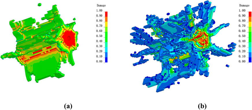
Figure 7. Measuring the volume range of damaged elements in crack zone and crushing zone (σ = 10 MPa) (a) Only display the damage elements in the crushing area (D > 0.9); (b) Only display the damage elements in the crack area (D > 0.9)
The extracted damage volumes under varying in-situ stresses are summarized in Figure 8. Curve fitting indicates distinct reduction patterns: the volume of the crushing zone (Vd) decreases exponentially from 602 cm3 to 342 cm3, representing a reduction of 43.2%. In contrast, the volume of the crack zone (Vc) exhibits a linear decline with a slope of −75.8 cm3/MPa, decreasing from 602 cm3 to 342 cm3, which corresponds to a 53.3% reduction. The significantly larger volume reduction compared to the decrease in radius can be attributed to two mechanisms: in-situ stress not only reduces the radial extents (rd and rc) but also suppresses both crack density and width, resulting in a dramatic decrease in the overall damaged volume.
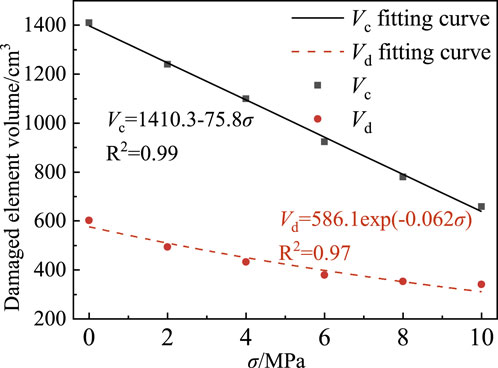
Figure 8. The relationship between the damage volume of crushed and cracked regions and in-situ stress.
3.4 Rock element failure modes
Figure 9 illustrates the temporal evolution of damage variables and principal stresses for elements within both damage zones under an in-situ stress of σ = 2 MPa. Figure 9a shows the damage progression in the crushing zone. At t = 2 μs, the rock element begins to experience compression, with the maximum principal stress rapidly increasing to approximately 300 MPa, significantly exceeding the rock’s compressive strength. Concurrently, the damage variable D rises sharply, reaching D = 1 (indicating complete loss of load-bearing capacity) by t = 4 μs.
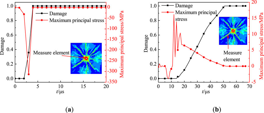
Figure 9. The time history curve of the damage value and the maximum principal stress of the unit in the crushing zone and crack zone (σ = 2 MPa) (a) Element damage in the crushing zone and the time history of the maximum principal stress; (b) Element damage in the crack zone and the time history of the maximum principal stress.
In contrast, Figure 9b illustrates the failure mechanism of elements in the crack zone. At t = 5 μs, the stress wave reaches the measurement point, inducing compressive stress (σmax = 9 MPa), which remains below the damage initiation threshold. However, subsequent radial displacement driven by explosive gas expansion generates tensile stress (σmax = 17 MPa), exceeding the tensile strength of granite. This leads to progressive damage accumulation starting at t = 15 μs, with D reaching one by t = 52 μs. Thus, failure in the crack zone is predominantly governed by tensile damage mechanisms, accompanied by a gradual degradation of load-bearing capacity.
4 Numerical simulation results of multiple V-shaped slots holes blasting
4.1 Numerical models of multiple V-shaped slots blast holes
Overbreak refers to the unplanned rock removal beyond the designed excavation profile, primarily driven by uncontrolled crack propagation into surrounding rock masses. Conversely, underbreak denotes incomplete fragmentation within the intended excavation boundary, leaving residual rock that requires secondary blasting or mechanical removal. Tunnel blasting overbreak and underbreak significantly increase rockfall clearance volumes and shotcrete consumption, impede construction progress, and result in uneven installation of waterproof panels that fail to conform to the irregular blasting contour. Overbreak and underbreak depths are critical indicators for evaluating the effectiveness of smooth blasting; however, the influence of in-situ stress on excavation accuracy remains poorly understood. Slotting blasting enhances directional fracture control by altering borehole geometry through the introduction of precisely oriented slots along the excavation contour of circular boreholes, thereby guiding energy release and crack propagation.
To investigate the combined effects of V-shaped slots holes arrangements and in-situ stress on excavation accuracy in underground chambers, a quasi-2D smooth blasting model with perimeter slotted holes was developed using the previously described methodology. The dimensions of the numerical model correspond to those of the model test, as illustrated in Figure 10. Key parameters include a semi-circular blasting contour with a radius of 26 cm, an 8 cm thick smooth blasting layer (Part 1), and seven equally spaced boreholes with identical parameters. The slots are oriented at 60° with a depth and width of 0.3 cm, an explosive charge diameter of 0.6 cm, and a coupling ratio of 1.6.
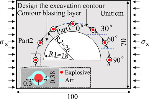
Figure 10. Schematic diagram of numerical model for V-shaped slots blast holes smooth blasting.
Through mesh sensitivity analysis, the model was optimized with a mesh size of 1 mm for the blasting layer and borehole walls, resulting in a total of 210,000 elements and a simulation duration of 150 μs. Boundary conditions were set as follows: the bottom was set as a fixed boundary, and the front and rear surfaces were free boundaries. Horizontal in-situ stress applied in the x-direction on the lateral boundaries, and slot orientations aligned tangentially to the design contour. The angular variation between in-situ stress and slot directions was incrementally set from 0° at the crown to 30°, 60°, and 90° at the haunch, allowing for a systematic analysis of stress-slot interactions.
4.2 Overbreak/underbreak depths and excavation ratio analysis
Figure 11 illustrates the excavation damage patterns under varying in-situ stress conditions. In all stress scenarios, interconnected cracks developed between adjacent boreholes, successfully achieving the blasting objectives of detaching and fragmenting the smooth blasting layer. This demonstrate confirming the effectiveness of the slotted-hole design in controlling energy release and fracture propagation under complex geomechanical constraints.
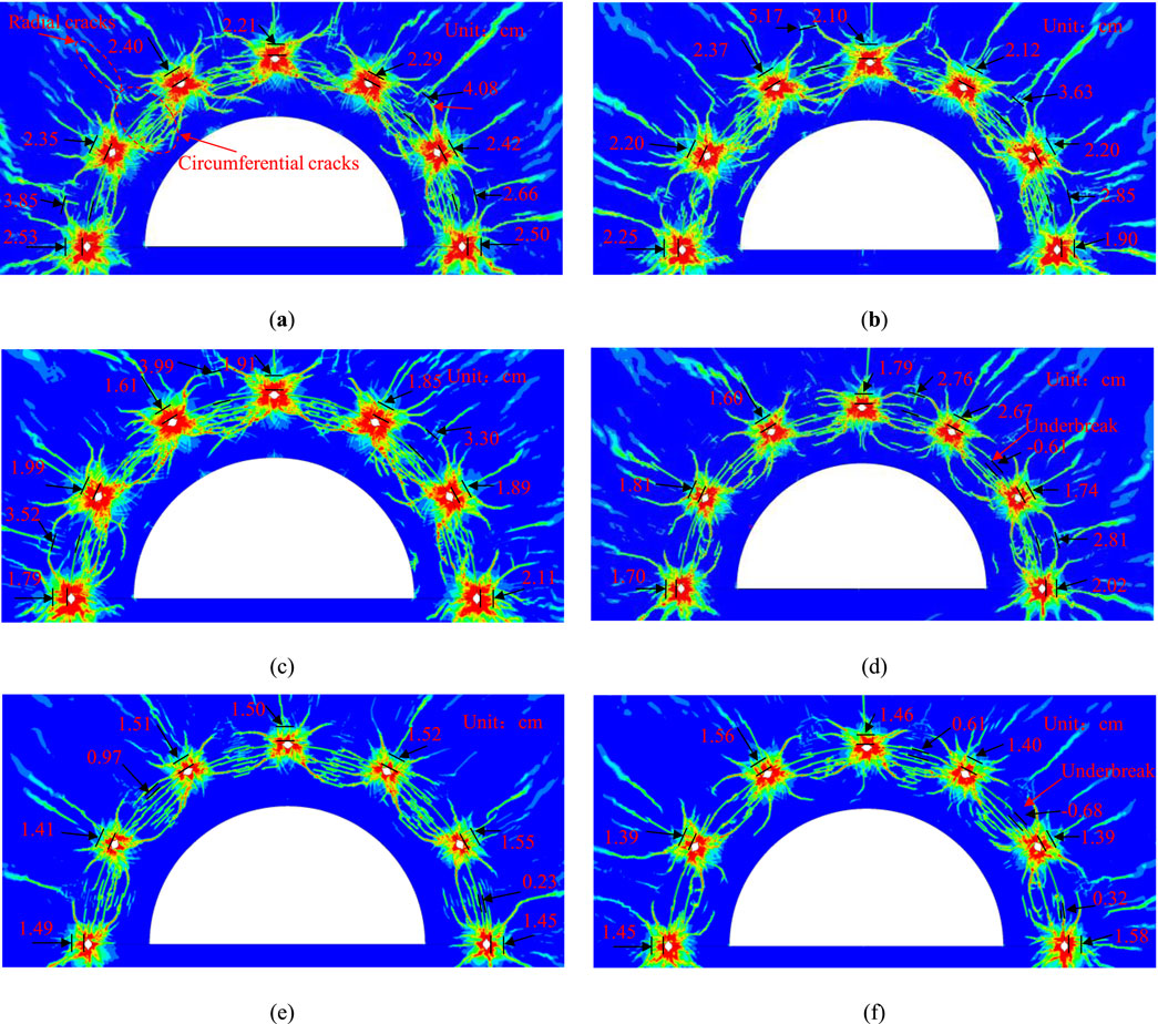
Figure 11. Damage contour visualization of V-shaped slots blast holes smooth blasting excavation: (a) σx = 0 MPa; (b) σx = 2 MPa; (c) σx = 4 MPa; (d) σx = 6 MPa; (e) σx = 8 MPa; (f) σx = 10 MPa.
To characterize the role of perimeter slotted holes in detaching the smooth blasting layer, the borehole wall pressure distribution at the crown position under stress-free conditions was extracted and scaled at a 1:1000 ratio, as shown in Figure 12. The maximum pressure of 402 MPa was recorded at the slot tip, while the minimum pressure of 145 MPa was observed at the circular borehole wall. This data demonstrates a consistent pressure gradient, indicating that the slot walls and tips experience significantly higher stresses than the circular walls. This suggests that slotting modifies the stress field at the tip, suppresses radial crack propagation, and effectively guides cracks to extend along the design contour, validating its suitability for smooth blasting.
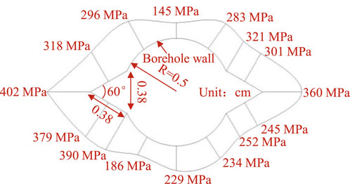
Figure 12. Borehole wall element pressure in slotted-hole blasting.
Consequently, the overbreak zone was defined as the interconnected circumferential cracks that extend beyond the design contour line, encompassing both the crushing zone and localized crack regions near the boreholes. The actual excavation depth deviations from the design contour were systematically quantified to assess overbreak and underbreak effects, with depth markers applied to each borehole and inter-borehole region for accurate evaluation.
As illustrated in Figure 11, under stress-free conditions, numerous circumferential cracks developed in the smooth blasting layer, resulting in extensive overbreak in the host rock. The maximum overbreak depth reached 4.08 cm, attributed to interconnected cracks within the surrounding rock, with additional overbreak observed near the boreholes due to the formation of a crushing zone.
At an in-situ stress of σX = 2 MPa, three overbreak zones persisted in the host rock, where blast-induced cracks partially interconnected, yielding a near-circular excavation contour with significant damage. When the in-situ stress increased to σX = 6 MPa, overbreak depths decreased to 2.81 cm and 2.76 cm, which were markedly smaller than those observed under stress-free conditions. The reduced density of circumferential cracks in the smooth blasting layer indicated incomplete fragmentation, likely leading to coarser rock blocks and less efficient muck pile handling. A localized underbreak of 0.61 cm emerged at the right haunch, suggesting that stress induced suppression of crack propagation occurred; nevertheless, partial layer detachment was still sufficient to achieve the excavation objectives.
At higher stress levels of σX = 8 MPa and σX = 10 MPa, crack propagation and rock fragmentation were significantly inhibited. Overbreak depths near the boreholes diminished to 0.23 cm and 0.32 cm, primarily due to effects from the crushing zone. Conversely, underbreak depths increased to 0.64 cm at the haunch and 0.68 cm at the sidewall, demonstrating a positive correlation between the severity of underbreak and the magnitude of in-situ stress. The sparse cracking in the smooth blasting layer implied a potential failure to meet fragmentation requirements in practice. These results highlight that increasing in-situ stress negatively impacts underbreak control and overall smooth blasting performance under fixed explosive parameters.
To mitigate mesh-induced irregularities in the simulated overbreak and underbreak distributions, a statistical analysis of average, minimum, and maximum deviations across the cases was conducted (Figure 13). Key trends identified include: the average overbreak depth decreased linearly by 61.5%, from 2.73 cm (stress-free) to 1.05 cm (σX = 10 MPa). The minimum overbreak depth exhibited a gradual reduction at σX ≤ 4 MPa, transitioning to underbreak (−0.68 cm) at higher stress levels. The maximum overbreak depth demonstrated an oscillatory decrease, achieving a 61.3% reduction at σX = 10 MPa.
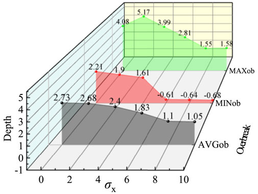
Figure 13. Average, minimum, and maximum overbreak depths under varying in-situ stresses.
To quantitatively evaluate the influence of in-situ stress on smooth blasting efficiency and excavation precision, the excavated areas of the smooth blasting layer (Part1) and host rock (Part2), denoted as ADi, were extracted using the aforementioned methodology. The excavation ratio αparti was defined as 1 = ADi/Aparti, where Aparti represents the total area of the smooth blasting layer or surrounding rock (Figure 14).
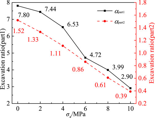
Figure 14. Excavation ratios of smooth blasting layer (part1) and surrounding rock (part2) under in-situ stress gradients.
Under stress-free conditions, the smooth blasting layer exhibited a high excavation ratio, indicating dense crack networks, severe damage, and complete fragmentation with finer rock fragmentation sizes. As in-situ stress increased to σX = 10 MPa, the excavation ratios of Part 1 and Part 2 decreased by 62.82% and 74.34%, respectively. While higher stresses effectively suppress host rock damage, this control comes at a critical trade-off: overbreak reduction often exacerbates underbreak issues. Specifically, excessive in-situ stress (σX > 6 MPa) induces underbreak and coarser fragmentation in the smooth blasting layer, compromising both excavation accuracy and muck handling efficiency.
4.3 Failure modes of inter-borehole radial crack elements
Radial cracks developed perpendicular to the line connecting two boreholes. The temporal evolution of maximum principal stress and damage in elements along these cracks is shown in Figure 15. At 20 μs, the compressive stress wave reached the measurement element, causing a rapid increase in maximum principal stress. By 30 μs, the stress peaked at 26 MPa–below granite’s compressive strength–without initiating damage. Subsequently, the stress state transitioned from compression to tension as the pressure wave subsided. At 65 μs, tensile stress reached 12 MPa, triggering rapid damage accumulation. Maximum damage occurred at 115 μs. This demonstrates the complex failure mechanism of inter-borehole radial cracks in dual-hole blasting: Compressive phase: Simultaneous detonation generated cylindrical compressive waves that superimposed at the mid-point between boreholes, inducing high compressive stress (26 MPa) without immediate damage. Tensile phase: Wave reflection converted compressive energy into tensile stress. When combined tensile stress exceeded the dynamic strength threshold, brittle tensile failure dominated damage evolution.
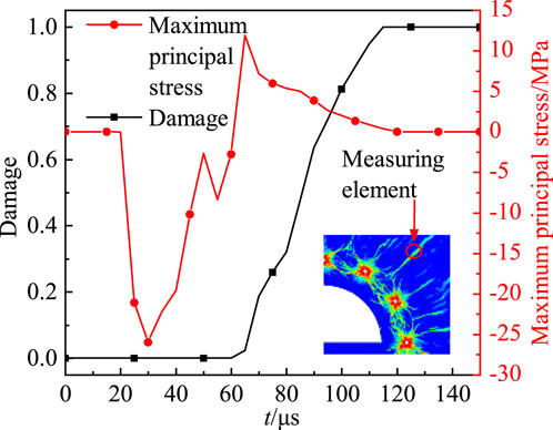
Figure 15. Damage evolution of radial crack elements between dual boreholes.
5 Discussion
In underground engineering constructed by the drill-and-blast method, conventional circular blast holes typically result in relatively uniform damage to the hole-wall rock mass during explosive detonation, with the resulting crushed zone generally forming a circular shape. To achieve directional control of blasting and guide crack propagation in a predetermined direction, some scholars have developed cumulative energy tubes (see Figure 16). By loading explosives inside these tubes and designing slits or openings in specific directions on the tube walls, the directional release of blasting energy is realized (Yin et al., 2025; Li et al., 2016; Zeng et al., 2018; Yin et al., 2021; Yang et al., 2019). In contrast, research on designing blast hole shapes for directional guidance remains scarce, though a few studies have verified the feasibility of this approach through numerical simulations, theoretical analyses, and experimental investigations (Liu et al., 2023; Liu et al., 2019; Zhu and Lu, 2017).
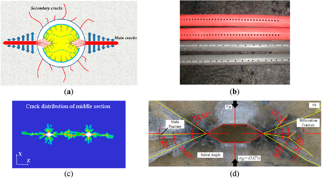
Figure 16. Directional blasting method and effect of cumulative energy device. (a) Jet flow diagram of double-groove shaped blasting (Yin et al., 2021); (b) bilateral cumulative tensile device (Yang et al., 2019); (c) deep hole presplitting blasting based on notched blasting (Liu et al., 2023); (d) Cracks details of horizontal slotting boreholes specimen (Liu et al., 2019).
This study aims to avoid complex charging procedures by modifying blast hole geometries to achieve directional blasting and improve smooth blasting performance, based on on-site construction conditions. Numerical simulations were conducted to systematically compare the results under different working conditions. However, the natural jointed fractures in actual strata significantly influence blasting effects. Due to the high technical difficulty of quantitatively characterizing jointed fracture parameters, this study did not account for their effects. Subsequent research will focus on blasting analyses considering joint influences, with the goal of providing more practical reference for drill-and-blast excavation projects.
6 Conclusion
This study developed numerical models for single-hole blasting and perimeter smooth blasting under in-situ stress, validated through six experimental groups with stress levels ranging from 0 to 10 MPa. Key findings include:
1. In single-hole blasting, rock damage was characterized by a crushing zone adjacent to the borehole and a peripheral crack zone. At low in-situ stress (σX ≤ 4 MPa), multiple radial cracks penetrated to the free surface, indicating severe damage. Conversely, at σX > 4 MPa, increased stress suppressed crack propagation, preventing primary radial cracks from reaching the surface.
2. Linear reductions of 8.38% in crushing zone radius and 13.30% in crack zone radius were observed with rising in-situ stress, with the crushing zone volume decreasing exponentially by 43.2% and the crack zone volume reducing linearly by 53.3%, primarily due to decreased crack density and width. In-situ stress exhibits a significantly stronger suppression effect on the extent of the crack zone than on the crushing zone.
3. Borehole pressure distributions showed stress concentrations of 402 MPa at slot walls and tips, significantly higher than 145 MPa at circular borehole walls. Grooving alters the stress field at the tip and guides crack propagation, making it suitable for smooth blasting. Under low-stress conditions, overbreak was driven by extensive circumferential cracks, while stress above 8 MPa inhibited crack interconnection. Underbreak increased with stress magnitude, peaking at 0.68 cm at σX = 10 MPa. Average overbreak depth decreased by 61.5%, leading to a 62.82% reduction in excavation efficiency and coarser fragmentation.
4. Stress-dependent failure modes were identified, with crushing zone elements failing due to compressive overload. Radial damage units first experienced compressive stress, followed by tensile damage from explosive gas effects. Radial crack units between blast holes initially experienced high compressive stress from superimposed waves, later failing under reflected tensile waves.
Data availability statement
The raw data supporting the conclusions of this article will be made available by the authors, without undue reservation.
Author contributions
CW: Writing – original draft, Writing – review and editing, Supervision, Resources. FL: Data curation, Writing – original draft, Writing – review and editing. BL: Supervision, Writing – original draft, Writing – review and editing. GL: Software, Writing – original draft, Writing – review and editing. BH: Writing – original draft, Writing – review and editing. XZ: Writing – review and editing. MN: Project administration, Writing – review and editing.
Funding
The author(s) declare that financial support was received for the research and/or publication of this article. This research was funded by National Natural Science Foundation of China (52204087), the Science and Technology Research Program of Chongqing Municipal Education Commission (Grant No. KJQN202200746) and the Natural Science Foundation of Chongqing Municipality (CSTB2023NSCQ-MSX0854).
Conflict of interest
Authors CW, FL, and BL were employed by Poly Changda Engineering Co. Ltd. Author MN was employed by Chongqing Chengtou Infrastructure Construction Co., Ltd.
The remaining authors declare that the research was conducted in the absence of any commercial or financial relationships that could be construed as a potential conflict of interest.
Generative AI statement
The author(s) declare that no Generative AI was used in the creation of this manuscript.
Publisher’s note
All claims expressed in this article are solely those of the authors and do not necessarily represent those of their affiliated organizations, or those of the publisher, the editors and the reviewers. Any product that may be evaluated in this article, or claim that may be made by its manufacturer, is not guaranteed or endorsed by the publisher.
References
Ainalis, D., Kaufmann, O., Tshibangu, J. P., Verlinden, O., and Louroussis, G. (2017). Modelling the source of blasting for the numerical simulation of blast-induced ground vibrations: a review. Rock Mech. Rock Eng. 50, 171–193. doi:10.1007/s00603-016-1101-2
Ding, C. X., Yang, R. S., and Yang, L. (2021). Experimental results of blast-induced cracking fractal characteristics and propagation behavior in deep rock mass. Int. J. Rock Mech. Min. Sci. 142, 104772. doi:10.1016/j.ijrmms.2021.104772
Foderà, G. M., Voza, A., Barovero, G., Tinti, F., and Boldini, D. (2020). Factors influencing overbreak volumes in drill-and-blast tunnel excavation. Tunn. Undergr. Space Technol. 105, 103475. . doi:10.1016/j.tust.2020.103475
Gou, Y., Ye, M., Yu, Z., Qiu, X., and Chen, Y. (2024). Experimental and theoretical analysis of charge length on single-hole vibration amplitude from underground deep-hole blasting. Int. J. Rock Mech. Min. Sci. 182, 105876. doi:10.1016/j.ijrmms.2024.105876
Guo, S., He, M., and Jeon, S. (2024). Visualization test and numerical simulations of 2D blasting crack propagation. J. Rock Mech. Geotech. Eng. doi:10.1016/j.jrmge.2024.10.013
Hong, Z., Tao, M., Cui, X., Wu, C., and Zhao, M. (2023). Experimental and numerical studies of the blast-induced overbreak and underbreak in underground roadways. Undergr. Space 8, 61–79. doi:10.1016/j.undsp.2022.04.007
Jayasinghe, L. B., Shang, J. L., Zhao, Z. Y., and Goh, A. T. C. (2019). Numerical investigation into the blasting-induced damage characteristics of rocks considering the role of in-situ stresses and discontinuity persistence. Comput. Geotech. 116, 103207. doi:10.1016/j.compgeo.2019.103207
Kumar, P., Mohammadi, H., Chopra, R., Tyagi, S. K., and Pandey, S. K. (2023). A newly developed blasting cut in tunnels: application of “combined method” in small to medium-sized tunnels. Tunn. Undergr. Space Technol. 142, 105426. doi:10.1016/j.tust.2023.105426
Li, C., Yang, R., Zuo, J., and Pei, P. (2025). Theory and field tests of innovative cut blasting method for rock roadway excavation. Tunn. Undergr. Space Technol. 155, 106180. doi:10.1016/j.tust.2024.106180
Li, X. B., Li, C. J., Cao, W. Z., and Tao, M. (2018). Dynamic stress concentration and energy evolution of deep buried tunnels under blasting loads. Int. J. Rock Mech. Min. Sci. 104, 131–146. doi:10.1016/j.ijrmms.2018.02.018
Li, X. P., Dong, Q., Liu, T. T., Luo, Y., Zhao, H., and Huang, J. H. (2016). Model test on propagation of blasting stress wave in jointed rock mass under different in-situ stresses. Chin. J. Rock Mech. Eng. 35, 2188–2196. doi:10.13722/j.cnki.jrme.2016.1004
Li, Z., Hu, Y., Wang, G., Zhou, M., Hu, W., Zhang, X., et al. (2023). Study on cyclic blasting failure characteristics and cumulative damage evolution law of tunnel rock mass under initial in-situ stress. Eng. Fail. Anal. 150, 107310. doi:10.1016/j.engfailanal.2023.107310
Liu, C. W., Lu, Y. Y., Xia, B. W., and Yu, P. (2019). Directional fracturing by slotting-blasting-caused stress wave form changes. Int. J. Impact Eng. 129, 141–151. doi:10.1016/j.ijimpeng.2019.02.002
Liu, J., and Zhang, J. (2024). Effect of loading waveform on the blasting crack propagation mechanism in single-hole and dual-hole blasting. Eng. Fract. Mech. 307, 110300. doi:10.1016/j.engfracmech.2024.110300
Liu, W., An, Y., and Zhou, J. (2024). Study on potential collapse of deep-buried tunnel induced by local overbreak obeying hoek-brown failure criterion. Undergr. Space Technol. 145, 105586. doi:10.1016/j.tust.2024.105586
Liu, X., Yan, P., Lu, W. B., Lu, A., Zhang, X. Y., Chen, M., et al. (2023). Numerical investigation of an improved deep-hole presplitting method based on notched blasting for deep-buried high sidewall structures. J. Build. Eng. 70, 106310. doi:10.1016/j.jobe.2023.106310
Ma, T., Li, F., Yang, Y., and Li, L. (2022). Study on energy evolution and crack propagation of rock mass under single hole uncoupled charge blasting. Appl. Eng. Sci. 11, 100112. doi:10.1016/j.apples.2022.100112
Mohammadi, H., Barati, B., and Chamzini, A. Y. (2018). Prediction of blast-induced overbreak based on geo-mechanical parameters, blasting factors and the area of tunnel face. Geotech. Geol. Eng. 36, 425–437. doi:10.1007/s10706-017-0336-3
Ni, Y., Wang, Z., Wang, J., Fu, J., Feng, C., Wang, S., et al. (2025). Numerical study on rock blasting fragmentation under the coupling effect of strength and environmental factors. Eng. Fract. Mech. 111, 111251. doi:10.1016/j.engfracmech.2025.111251
Qiu, J. D., Liu, K., Li, X. B., Li, D. Y., and Wang, F. (2022). Influence of blasting disturbance on dynamic response and safety of deep tunnels. Geomech. Geophys. Geo-energ. Geo-resour. 8, 5. doi:10.1007/s40948-021-00308-8
Shadab Far, M., Wang, Y., and Dallo, Y. A. (2019). Reliability analysis of the induced damage for single-hole rock blasting. Georisk 13, 82–98. doi:10.1080/17499518.2018.1508728
Xie, L., Lu, W., Jiang, Q., Zhang, Q., Wang, G., Chen, M., et al. (2017). Damage evolution mechanism of deep rock mass in process of cut blasting. J. Cent. South Univ. 48, 1252–1260. doi:10.1016/j.tust.2020.103475
Yang, J., Peng, C., Ye, Z., Yao, C., Zhang, X., Ma, Y., et al. (2025). Study on the efficiency of energy transfer in the blasting with different coupling mediums for deep rock mass excavation. Eng. Fract. Mech. 319, 111048. doi:10.1016/j.engfracmech.2025.111048
Yang, J. C., Liu, K. W., Li, X. D., and Liu, Z. X. (2020). Stress initialization methods for dynamic numerical simulation of rock mass with high in-situ stress. J. Cent. South Univ. 27, 3149–3162. doi:10.1007/s11771-020-4535-3
Yang, X. J., Liu, C. K., Ji, Y. G., Zhang, X. Y., and Wang, S. (2019). Research on roof cutting and pressure releasing technology of directional fracture blasting in dynamic pressure roadway. Geotech. Geol. Eng. 37, 1555–1567. doi:10.1007/s10706-018-0707-4
Yin, Y., Esmaeili, K., Sun, Q., and Cao, J. (2025). Numerical investigation of rock damage induced by bilateral-groove-slot shaped charge blasting under the influence of in-situ stresses. Comput. Geotech. 180, 107070. doi:10.1016/j.compgeo.2025.107070
Yin, Y., Sun, Q., Zou, B. P., and Mu, Q. Y. (2021). Numerical study on an innovative shaped charge approach of rock blasting and the timing sequence effect in microsecond magnitude. Rock Mech. Rock Eng. 54, 4523–4542. doi:10.1007/s00603-021-02516-w
Zeng, S., Wang, S. P., Sun, B., and Liu, Q. B. (2018). Propagation characteristics of blasting stress waves in layered and jointed rock caverns. Geotech. Geol. Eng. 36, 1559–1573. doi:10.1007/s10706-017-0410-x
Zhang, W., Liu, D., Tang, Y., Qiu, W., and Zhang, R. (2023). Multifractal characteristics of smooth blasting overbreak in extra-long hard rock tunnel. Fractals 7, 842. doi:10.3390/fractalfract7120842
Zhang, Z. H., Gao, W. L., Li, K. P., and Li, B. J. (2020). Numerical simulation of rock mass blasting using particle flow code and particle expansion loading algorithm. Simul. Model. Pract. Theory 104, 102119. doi:10.1016/j.simpat.2020.102119
Zhou, C., Yan, P., Liu, X., Lu, W., Wang, X., Gao, Q., et al. (2025). Investigation of blasting-induced rock fracturing process under an arcuate free face. Eng. Fract. Mech. 111, 111217. doi:10.1016/j.engfracmech.2025.111217
Keywords: smooth blasting, blast hole, in-situ stress, crack propagation, overbreak and underbreak
Citation: Wu C, Luo F, Li B, Lin G, Hu B, Zhang X and Nie M (2025) Influence of blast hole shape and in-situ stress on blast damage evolution in granite by numerical simulation. Front. Earth Sci. 13:1645740. doi: 10.3389/feart.2025.1645740
Received: 12 June 2025; Accepted: 17 July 2025;
Published: 05 August 2025.
Edited by:
Wenling Tian, China University of Mining and Technology, ChinaReviewed by:
Jin Jiaxu, Liaoning Technical University, ChinaPing Chang, Curtin University, Australia
Copyright © 2025 Wu, Luo, Li, Lin, Hu, Zhang and Nie. This is an open-access article distributed under the terms of the Creative Commons Attribution License (CC BY). The use, distribution or reproduction in other forums is permitted, provided the original author(s) and the copyright owner(s) are credited and that the original publication in this journal is cited, in accordance with accepted academic practice. No use, distribution or reproduction is permitted which does not comply with these terms.
*Correspondence: Bin Li, YmluX2xpcGNlY0AxMjYuY29t