 Taifeng Li1,2
 Xin Feng
- 1Yunnan Provincial Highway Administration Corps, Kunming, China
- 2Yunnan Comprehensive Transportation Development Cente, Kunming, China
- 3CCCC Second Harbor Engineering Co., Ltd., Wuhan, China
- 4CCCC(Guangzhou) Construction Co., Ltd., Guangzhou, China
When traversing strata characterized by highly developed karst formations, shield tunneling machines are susceptible to incidents such as head sinking, surface collapse, and water inrushes. Consequently, karst reinforcement becomes a critical factor in ensuring the safety and success of shield tunneling operations in such geological conditions. However, conventional grouting technologies often face challenges, including severe grout leakage and suboptimal reinforcement outcomes, thereby introducing significant risks to tunneling activities. In this study, the limitations of traditional sleeve-valve pipe grouting technologies in reinforcing karst strata were examined, using the Dapeng Branch Line project of the Shenzhen-Huizhou Intercity Railway as a case study. To address these issues, a mold-bag sleeve-valve pipe grouting technology, specifically designed for karst reinforcement, was developed. Its construction procedures and key technical aspects were systematically investigated, and a field grouting test was performed to assess the applicability and reliability of the proposed method. The results indicated that, in karst strata with extensively developed fissures, conventional sleeve-valve pipe grouting methods encountered significant problems, including grout leakage, grout surfacing, and the inability to retrieve intact reinforced bodies from karst cavities. Consequently, the karst treatment effect failed to meet the requirements. In contrast, the proposed mold-bag grouting technology enables precise grouting in karst cave areas, reducing grout loss and forming complete reinforced bodies within the karst cave areas.
1 Introduction
Currently, tunnel construction is under rapid development in China. This status manifests not only as a rapid increase in the number and length of tunnels but also as large breakthroughs in construction equipment, construction technology, and environmental protection (Editorial Department of China Journal of Highway and Transport, 2022; Tan et al., 2023; Tan et al., 2024). The shield tunneling method, as a leading construction approach in contemporary China, has found widespread application in the development of urban rail transit, highway, and railway tunnels (Dai and Ji, 2022; Meng et al., 2025).
Karst strata are extensively distributed across China, with 7 major karst regions. In southern China, many karst strata, with high water content, permeability, and susceptibility to collapse, exist (Cui et al., 2015). With the rapid development of rail transit, tunnel construction must inevitably traverse karst-developed zones. However, when passing through karst strata, shield tunneling machines can easily encounter accidents such as head sinking, surface collapse, and water bursts (Yan et al., 2021; Zhu et al., 2021). Existing studies on tunnel construction in karst strata have focused mainly on risk assessment and karst treatment. In terms of risk assessment, Li et al. (2020) established an earth pressure balance shield model test system to investigate the mechanism of water bursts in shield tunneling through karst strata. Zhang et al. (2022) normalized the evaluation indicators and determined their weights using a comprehensive weighting approach that integrated the fuzzy analytic hierarchy process (FAHP) with correlation analysis. Based on these weighted indicators, they enhanced the extended assessment method and developed a risk assessment system for ground collapse along tunnel alignments in karst strata. Sun et al. (2024) incorporated four probability models into a two-dimensional cloud model to quantify risk levels, applying the improved model to evaluate the risk probability associated with shield tunneling in karst regions. Building on the cloud model and FAHP, Meng et al. (2021) proposed a risk assessment method for shield tunneling in karst strata and established a corresponding indicator system, consisting of four primary indicators and 17 secondary indicators, along with defined risk classification criteria. In terms of karst strata treatment, grouting remains the most widely used method (Brantberger et al., 2000; Zhang et al., 2018). Qian et al. (2016) used sleeve-valve pipe grouting technology to reinforce a sandy soil-covered karst stratum and achieved good results. Yang et al. (2020) proposed a grouting reinforcement technology for underwater karst areas, in which controllable cement-bentonite fly ash and hardened cement-bentonite grouting materials were adopted. Huang et al. (2021) reported a multi-step combined control technology for karst treatment during shield tunneling in spring areas. The steps included karst exploration, multi-step grouting, and optimization of the tunneling parameters. The multi-step grouting process involved pre-grouting, as well as filling large karst caves with rubble from the ground surface, injecting a small volume of inert grout into the tunnel many times, and conducting secondary grouting at the tail of the shield tunneling machine.
The reinforcement effectiveness of karst strata before shield tunneling plays a crucial role in ensuring tunneling safety. To address this, researchers have advanced existing grouting methods and developed new technologies and materials specifically for karst reinforcement. Nevertheless, the issue of grout leakage in karst strata with developed fissures and high connectivity has yet to be fully resolved. In this study, a mold-bag sleeve-valve pipe grouting technology, adapted from Mold-bag grouting used for soft foundation reinforcement (Li et al., 2018), was introduced for application in karst strata. The construction procedure and technical parameters of this method were thoroughly investigated, and its performance was compared to that of conventional sleeve-valve pipe grouting technology, using the Dapeng Branch Line of the Shenzhen-Huizhou Intercity Railway as a practical example. The outcomes offer valuable insights for the implementation of the proposed technique.
2 Background of the project
2.1 Overview
The Dapeng Branch Line of the Shenzhen-Huizhou Intercity Railway serves as a crucial component of the intercity railway network in the Greater Bay Area. Together with the Zhongnanhu Intercity Railway and the Tanglong Intercity Railway, it forms the primary intercity corridor traversing the Pearl River Estuary, linking the eastern and western banks. According to the Greater Bay Area intercity railway development plan, the Dapeng Branch Line connects with both the Tanglong and Zhongnanhu Intercity Railways, enabling rapid transit between the eastern part of Shenzhen and the cities of Dongguan and Zhongshan. The line originates at Longcheng Station, an interchange station on the Shenzhen-Huizhou Intercity Railway, and extends to Xinda Station in the Dapeng New Area, passing through Longgang District, Pingshan District, and Dapeng New Area. The entire line, with a total length of 39.387 km, is constructed underground. It includes six stations—Longcheng, Pingshan, Yanzihu, Kuiyong, Dapeng, and Xinda—and features a parking facility at Xinda. The layout of the line is shown in Figure 1.
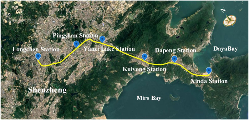
Figure 1. Schematic plan of the Dapeng Branch Line in the Shenzhen-Huizhou Intercity Railway.
Work Zone 1 of the line encompasses the segment from Longcheng Station to Longping Working Shaft 1, spanning 3,064.5 m, and the segment from Longping Working Shaft 1 to Longping Working Shaft 2, extending 3,067.4 m. The shield tunneling method is utilized for construction throughout both segments (Figure 2). Longping Working Shafts 2 and 3 are interconnected by a rear pilot tunnel measuring 42.3 m in length, which is excavated using the mining method.
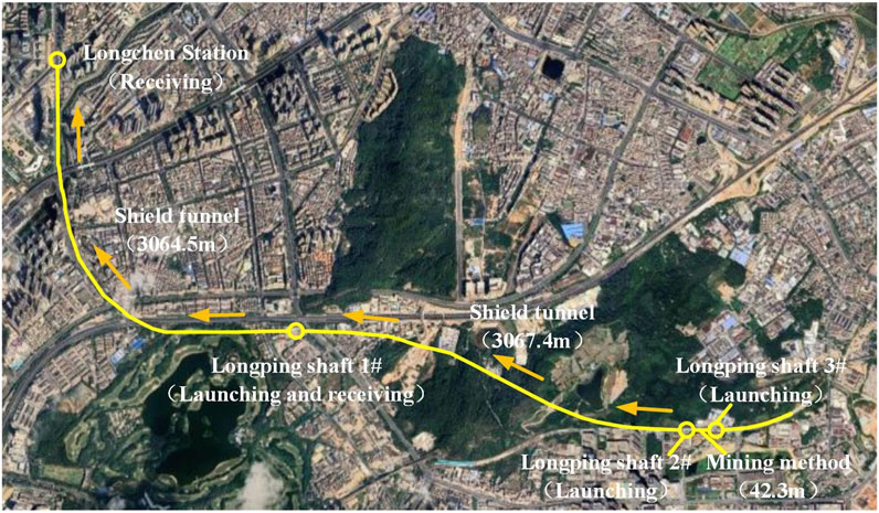
Figure 2. Schematic plan of the route in Work Zone 1 for the Dapeng Branch Line of the Shenzhen-Huizhou Intercity Railway.
2.2 Geological condition
Along the project route in Work Zone 1, there are complex geological and hydrological conditions, a wide variety of geotechnical layers, and unfavorable geological conditions such as karst and erosion-induced fractures. The burial depth, thickness, and properties of geotechnical layers vary greatly. The sectional tunnels include moderately to slightly weathered limestone, erosion-induced fracture zones of limestone, and developed karst areas. The geological strata within the construction zone are composed mainly of plain fill, muck, silty clay, medium to coarse sand, clay, highly weathered siltstone, moderately weathered siltstone and limestone, and slightly weathered limestone. Notably, the highly and moderately weathered rock formations exhibit significant fissure development. The physical characteristics of these strata are detailed in Table 1. The groundwater system is predominantly comprised of Quaternary pore water, bedrock fissure water, and karst water. The Quaternary pore water is mainly replenished through atmospheric precipitation and surface water infiltration, leading to a high water yield. The bedrock fissure water is replenished mainly by pore water, whereas the karst water is recharged by lateral runoff and leakage. Pumping tests have revealed good connectivity among karsts and a large volume of fissure-karst water within the construction area.
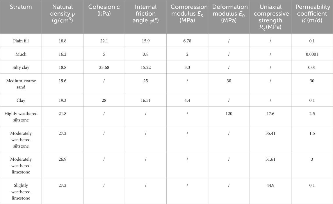
Table 1. Physical and mechanical parameters of strata.
2.3 Karst development characteristics and treatment principles
In this project, geological drilling and cross-hole CT methods were used for karst exploration. The exploration results indicated that the karsts in the construction area were covered and highly developed and primarily developed in the form of karst caves and dissolution fissures. The karst formations exhibited good connectivity, with some caves interconnected, forming bead-like karst caves. A total of 474 karst caves were uncovered in the shield tunneling section, including 270 empty caves, 94 semi-filled karst caves, 77 fully filled karst caves, and 33 soil caves. The karst caves were mainly filled with silty clay and gravelly soil. Karst caves were found in diverse locations relative to the shield tunnel, encompassing those within/above/below the tunnel and on both sides of the tunnel (Figure 3).
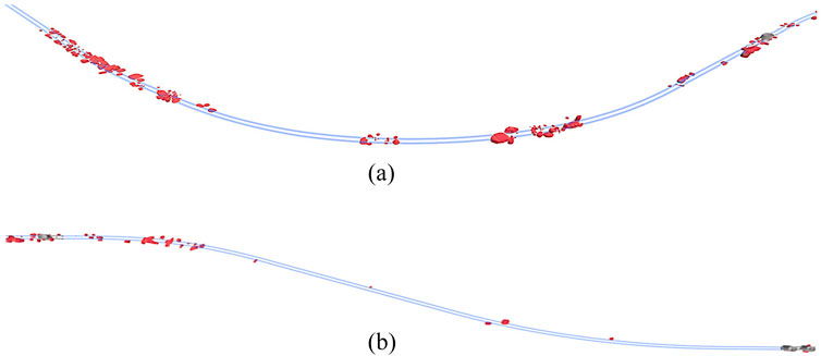
Figure 3. Distribution of karst caves in the shield tunneling sections. (a) Tunneling section from Longcheng Station to Longping Working Shaft 1. (b) Shield tunneling section from Longping Working Shaft 1 to Longping Working Shaft 2
To ensure construction safety, karst caves should be treated before shield tunneling. The karst treatment principles were formulated as follows after a comprehensive consideration of the types, locations, and sizes of karsts, as well as the status of karst water (Figure 4):
1) All karst caves within 3 m on the top and both sides of the tunnel, as well as within 5 m below the tunnel bottom, should be treated;
2) All empty caves on the top of the tunnel should be treated;
3) Karst caves within 5 m–10 m below the tunnel bottom should be treated if the height H of the stable rock surface roof of the karst cave is less than 3 m or if the ratio of the height H of the stable rock surface roof of the karst cave to the span B of the karst cave is less than 1;
4) For any extra large karst cave (height: >5 m) found beyond the mentioned treatment ranges, a special meeting should be held to determine the necessity of treating it, considering the uncertainty of karst cave development.
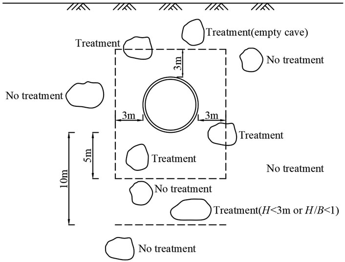
Figure 4. Schematic diagram of the karst cave treatment principles.
According to the mentioned treatment principles, the karst caves requiring treatment within the shield tunneling section of Work Zone 1 are detailed in Table 2.
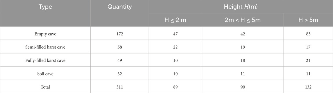
Table 2. Karst caves requiring treatment.
The requirements for cave treatment are as follows.
1) The unconfined compressive strength of fully filled karst caves after grouting treatment should be greater than 0.2 MPa.
2) For unfilled or semi filled caves, the unconfined compressive strength of the filling material should be greater than 0.8 MPa.
3 Conventional sleeve-valve Pipe grouting technology
3.1 Grouting Scheme
3.1.1 Treatment method
For semi-filled karst (soil) caves greater than 3 m and empty caves greater than 2 m, the first step was to fill them with C15 plain concrete; then, sleeve-valve pipe grouting technology was employed for grouting in the segments. This approach enabled loose fillings within the karst caves, as well as the voids formed after plain concrete was filled, to be compacted and permeated by cement grout, forming a consolidated mass (Figure 5). Fully-filled karst (soil) caves, semi-filled karst (soil) caves with heights less than 3 m, and empty caves not exceeding 2 m were directly treated using the sleeve-valve pipe grouting method (Figure 6). For karst caves extending beyond the specified treatment boundaries, edge sealing was performed prior to grouting by injecting a double-liquid mixture of cement and sodium silicate.
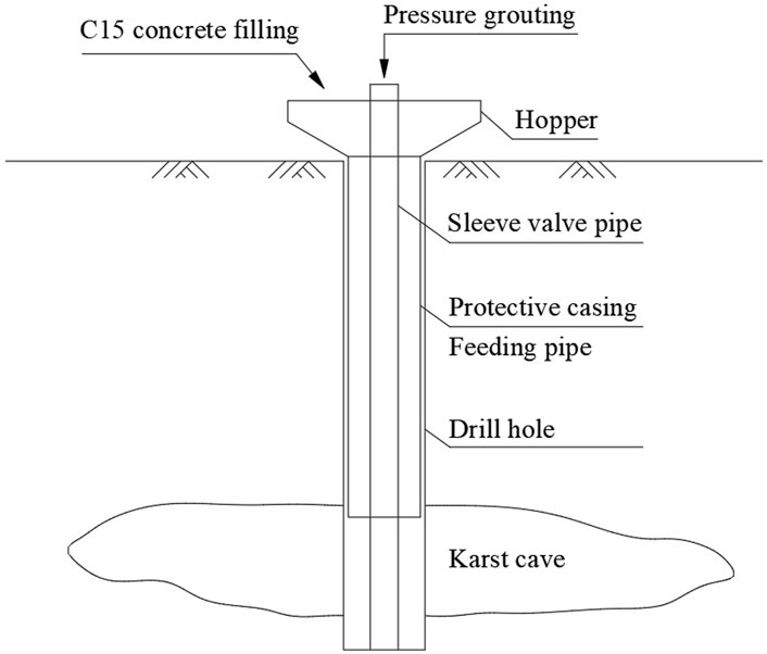
Figure 5. Schematic diagram of plain concrete filling and sleeve-valve pipe grouting.
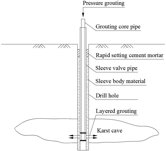
Figure 6. Schematic diagram of sleeve-valve pipe grouting.
3.1.2 Layout of grouting holes
Before karst caves are treated, their planar ranges should be detected. First, edge exploratory boreholes were drilled along the outline of the karst caves as determined by geophysical prospecting. If a karst cave is exposed during drilling, additional boreholes should be drilled 2 m outward from the exposed point to determine the cave boundary. After the planar dimension of the karst cave is determined, the grouting holes should be arranged according to the following principles:
1) For any karst cave exposed with a side length of less than 2 m in the projected area, one grouting hole should be arranged at the exploratory borehole uncovering it;
2) For any karst cave exposed with a side length of 2–3 m in the projected area, three grouting holes should be arranged with a spacing of 2 m × 2 m in a triangular pattern around the exploratory borehole.
3) For any karst cave exposed with a side length greater than 3 m in the projected area, grouting holes should be arranged with a spacing of 2 m × 2 m in a quincunx pattern around the exploratory boreholes uncovering it;
4) The grouting holes should extend 0.5 m below the bottom of the karst cave. When the karst cave is large in scale or has developed fissures, the drilling should be deepened to extend 0.5 m into the intact rock mass beneath the karst cave;
5) Boreholes to be filled with plain concrete should be inserted with Φ200 mm PVC pipes and distributed uniformly with a spacing of 5–6 m along the boundary of the karst cave;
6) In addition to grouting holes, vent holes should also be set aside. The number of vent holes should be determined per the scale of the karst cave.
3.1.3 Grouting materials and parameters
1) Grouting materials
The grouting materials consisted of two types: cement grout and double-liquid grout composed of cement and sodium silicate. The cement grout was prepared using P.O42.5 cement with a water-to-cement ratio of 1:1. The sodium silicate solution, initially having a density of 1.325 g/mL, a modulus of 3.25, and a Baume degree of 37°Bé, was diluted at a 1:1 ratio. The volume ratio between the cement grout and the diluted sodium silicate solution was maintained at 1:1.
2) Grouting parameters
After grouting commenced, the grouting core pipe pressed the grout upward from the bottom. The grouting rates at the bottom and top of the karst cave were 20–50 L/min, whereas those at the other parts were 30–70 L/min. The grouting core pipe was lifted 1 m in a single operation, and the grouting volume for each segment was controlled within 0.8–2 m3. The initial grouting pressure was set at 0.2–0.3 MPa. The grouting pressure was terminated at 1.5 MPa and maintained at this value for 10 min.
3.2 Application effect
Owing to the presence of irregularly developed karsts, rock fissures, and loose overlaying layers, sleeve-valve pipe grouting has resulted in severe grout leakage and increased grout volume. Moreover, multiple instances of grout surfacing were observed during grouting, causing substantial pollution to the surrounding environment. After the completion of grouting, the reinforcement effect was tested via the drilling and coring methods. As a result, in many karst caves, no intact reinforced bodies were observed, or the reinforced bodies extended beyond the boundaries of the karst caves (Figures 7, 8). This required secondary treatment, leading to increased construction costs and elevated safety risks. Based on the field application results, the conventional sleeve-valve pipe grouting technology demonstrated notable limitations and insufficient reinforcement performance in karst strata characterized by well-developed fissures and high connectivity.
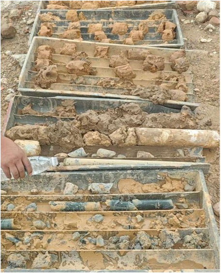
Figure 7. No complete reinforcement bodies.
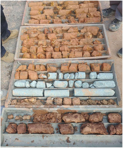
Figure 8. Reinforced bodies beyond the ranges of the karst caves.
4 Mold-bag sleeve valve pipe grouting technology
4.1 Technical principles
In this method, grout leakage was mainly mitigated by wrapping a high-strength geotextile mold bag around the sleeve-valve pipe, effectively restricting grout diffusion as the solid particles were unable to penetrate the mold. The dimensions of the mold bag were tailored on-site according to the size of the karst cavity, ensuring that its height and diameter matched the vertical and horizontal measurements of the cave. The bottom of the mold bag was sealed, while the top remained open to allow insertion of the sleeve-valve pipe. Multiple loops of thin iron wire were wound around the exterior of the mold bag at intervals of 1.0–1.5 m, serving as pressure control valves during grouting. The top of the mold bag was tightly secured with iron wire to prevent grout from escaping at the upper end. The assembly was then lowered into the karst cavity, and grouting was carried out in stages using the standard sleeve-valve pipe grouting technique. This process allowed the mold bag to expand incrementally from the bottom up, ultimately creating a continuous and complete reinforced body within the karst cavity (Figure 9).
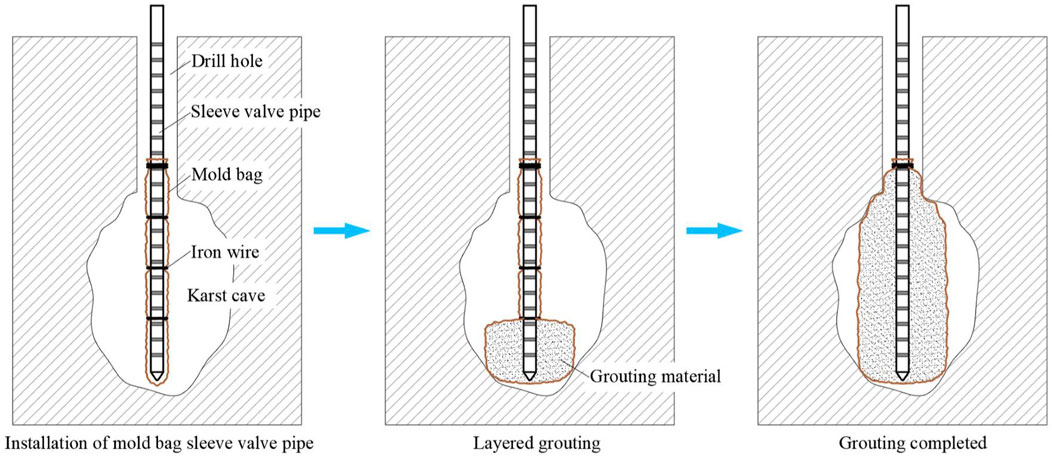
Figure 9. Schematic diagram of mold-bag sleeve valve pipe grouting in karst strata.
4.2 Field test
4.2.1 Test site
The test site was located in the karst area in front of the entrance gate of Nanyuechun Banquet Manor. The total depth of the test borehole was 48.8 m. As discovered by coring, the upper 25 m of the borehole consisted of silty clay, whereas the lower part was composed of moderately weathered limestone. At depths of 44–46.2 m underground, a semi-filled karst cave was found (Figure 10) and treated as the primary focus of the test.
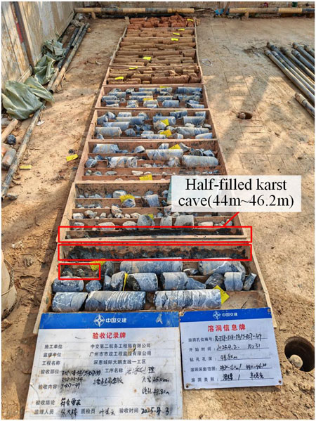
Figure 10. Coring from test boreholes.
4.2.2 Test materials
The mold bag was made of a filamentous-woven geotextile with a diameter of 1 m, a height of 4 m, a breaking strength of 150 kN/m, an elongation rate of about 20% at break, and a weight of 550 g/m2. The sleeve valve pipes were Φ 48 mm PVC sleeve-valve pipes (length: 4 m/pcs). The grouting material was cement grout with a water:cement ratio of 1:1.
4.2.3 Test procedures
1) Binding of the Mold Bag
Initially, the sleeve-valve pipe was positioned within the central portion of the mold bag, with its bottom end maintained about 10 cm above the sealed base of the mold bag. The mold bag was then folded in half and rolled into a cylindrical form. Its upper end was securely tied with a Φ1.2 mm iron wire to prevent grout leakage. Pressure valves were arranged along the central section of the mold bag at intervals of 1.25 mm, created by wrapping four turns of Φ1.2 mm iron wire. During ground tests, the mold bag was able to unfold smoothly throughout the grouting process.
He measured diameter of the mold bag bound to the sleeve valve pipe was 10 cm–11 cm. Hence, the diameter of the test borehole should be more than 110 mm. In addition, the karst cave in this stratum was buried at a considerable depth and surrounded by thick and intense rock layers. Drilling operators reported that the maximum achievable borehole diameter was 110 mm; if this diameter was exceeded, drilling would be quite difficult. Therefore, the diameter of the test borehole was determined to be 110 mm.
2) Drilling
Test boreholes were drilled to a diameter of 110 mm per dimension of the bound mold bag. Coring was conducted from the entire length of the borehole during drilling, and the coring results were used to determine the location and height of the karst cave. As illustrated, there were semi-filled karst caves at depths of 44–46.2 m from the ground surface.
3) Installation of Sleeve-valve Pipes
Upon completion of drilling, the sleeve-valve pipe, wrapped with the mold bag, was positioned at the lowest section for insertion into the borehole. The target depth for the mold bag was about 20 cm below the base of the karst cavity. However, during the actual lowering process, insertion was halted after 11.5 sleeve-valve pipes had been placed, likely due to sediment buildup at the bottom of the borehole. At this point, the bottom of the mold bag was positioned roughly at the base level of the karst cavity.
4) Installation of the Grouting Pipe
After the installation of sleeve-valve pipes, the borehole was sealed. Specifically, the area from the ground surface around the borehole opening to a depth of 2 m underground was sealed using quick-setting cement mortar. The grouting pipes (DN20 steel pipe) were then installed, with the grouting head placed at the bottom and lowered to the bottom of the sleeve-valve pipe. During the actual installation, further lowering was not possible after 22 grouting pipes (each 2 m in length) had been inserted into the sleeve-valve pipes. As a result, the bottom of the grouting core pipe was positioned about 44.2 m below ground level, maintaining a distance of about 1.8 m above the bottom of the mold bag. This configuration accounted for the exposed length of the grouting pipe, the length of the grouting core pipe, and the length of the pipe joints. The spatial relationship among the karst cavity, mold bag, and grouting core pipe is illustrated in Figure 11.
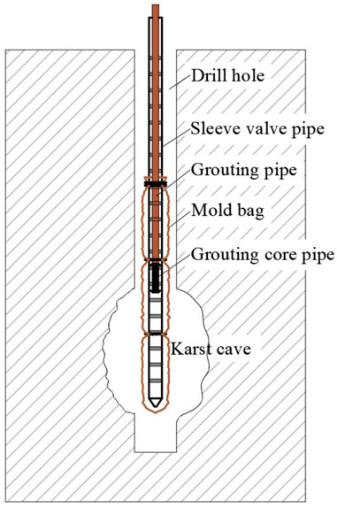
Figure 11. Schematic diagram showing the relative positions of the karst cave, mold bag, and grouting core pip.
5) Grouting
Following the installation of the grouting pipe, a pressure gauge was attached to its upper section. Prior to grouting, the pipes were flushed with water to ensure they remained unobstructed. Grouting was performed in segments, with the grouting core pipe being raised by 0.5–1.0 m for each segment. The grouting process was regulated by monitoring both the grouting volume and pressure. When the size of the cave was larger than the diameter of the mold bag, the grouting amount can be controlled according to the volume of the mold bag. When the volume of the cave was small, the amount of grouting cannot be accurately estimated. Both of the above states can be judged by changes in grouting pressure. When there was a significant increase in grouting pressure, it indicates that the mold bag in this section has been basically filled, and the next section of mold bag grouting can be carried out. In this test, the volume per unit length of the mold bag was 0.7854 m3, and the estimated volume of grout required within the height range of the karst cave (2.2 m) was about 1.73 m3. In existing cases, the grouting pressure for mold bags is generally controlled within the range of 1.0–1.5 MPa. During the test, the grouting pressure was observed continuously.
Because the grouting core pipe was close to the top of the karst cave, it was not feasible to grout in segments within the karst cave area. Thus, the grouting core pipe remained stationary during grouting. In the field grouting process, the initial grouting pressure was about 0.2–0.6 MPa. After about 30 s, the grouting pressure stabilized at 0.8 MPa–1.2 MPa. The reason was that after 30 s of grouting, the slurry reached the grouting core pipe and overcomed the water pressure on the outside of the rubber sleeve to start grouting into the mold bag The grouting was halted after about 50 min of continuous grouting. In total, about 3.2 t of cement grout was grouted. Given that the specific gravity of the cement grout used on-site was 1.46 g/cm3, the volume of the grout was calculated to be 2.19 m3. However, the actual grouting volume exceeded the theoretical grouting volume for the following reasons: (1) the karst cave was actually greater than 2.2 m; (2) some water in the cement grout seeped out from the mold bag, resulting in an increased grouting volume.
4.2.4 Grouting effect test
Two weeks after the completion of grouting, the area 20 cm away from the test borehole was drilled to a depth identical to the test borehole and then cored, with the corresponding results displayed in Figure 12. The karst cave area was filled with cement grout. In detail, the rock cores at depths of 44–45 m were complete, indicating that this segment of the mold bag was sufficiently filled with cement grout. The reason was that the grouting core pipe was positioned in the middle part of the two pressure valves, and the grouting was conducted here consistently. Additionally, the rock cores obtained from depths of 45 m–46.2 m were fragmented, indicating an unsatisfactory filling effect of the cement grout in this section. This was attributed to the loosening of the pressure valves in the upper and lower portions of the mold bag under the influence of grouting pressure after the central part had been filled. As a result, cement grout was able to flow into the upper and lower sections of the mold bag; however, the grout flow was uneven.
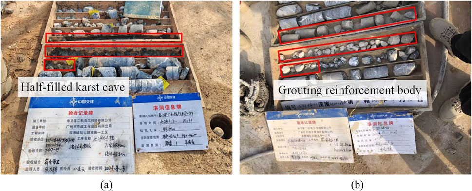
Figure 12. Comparison of rock cores before and after grouting. (a) Before grouting. (b) After grouting.
4.3 Application analysis
On the whole, it was feasible to apply mold-bag sleeve valve pipe grouting technology for karst strata reinforcement. However, the following points should be noted:
4.3.1 Drilling depth
Owing to sediment accumulation at the bottom of the borehole, the drilling depth should extend 2–3 m below the bottom of the karst cave to ensure that the mold bag can be lowered to the bottom of the karst cave smoothly.
4.3.2 Matching between the diameters of the borehole and the mold bag
As the diameter of the mold bag increases, its size, after being wrapped around the sleeve-valve pipe, also expands, necessitating a proportionally larger drilling diameter. In formations with deep karst cavities, enlarging the drilling diameter significantly raises both the complexity and the cost of drilling operations.
4.3.3 Lowering sleeve-valve pipes and grouting pipes
For greater drilling depths, steel sleeve-valve pipes may be employed to prevent breakage during the lowering process. Mechanical equipment can be utilized to assist in positioning both the sleeve-valve pipes and the grouting pipes.
4.3.4 Grouting in segments
Grouting should be performed from the bottom up to ensure that each segment of the mold bag is filled.
Owing to the characteristics of mold-bag sleeve valve pipe grouting, this technology is mainly used in the following aspects of karst strata treatment:
1) For empty caves with limited horizontal dimensions, as well as fully-filled and semi-filled karst caves, a single mold bag is sufficient for grouting reinforcement.
2) Edge sealing for karst caves. The mold-bag sleeve-valve pipe grouting technique can be applied to construct a pile-like barrier along the edges of the karst cavity or treatment zone, thereby enhancing the effectiveness of edge sealing.
5 Conclusions and Suggestions
This study analyzed the use of conventional sleeve-valve pipe grouting technology for reinforcing karst strata, taking the Dapeng Branch Line project of the Shenzhen-Huizhou Intercity Railway as a reference. A mold-bag sleeve-valve pipe grouting technique, specifically designed for karst conditions, was then proposed, and its implementation process and performance were assessed. The main conclusions derived from the study are as follows:
1) In karst strata with developed fissures and good connectivity, the application of conventional sleeve-valve pipe grouting technologies could cause severe grout leakage and grout surfacing. As a result, no completely reinforced bodies were formed within the karst cave area, which necessitated secondary treatment, increasing the construction cost and safety risk.
2) The proposed grouting technology enables precise grouting within the karst cave area, reducing grout loss and improving the reinforcement effect on karst strata. This method demonstrated good applicability in karst treatment during shield tunneling.
3) When the proposed grouting technology for karst treatment was utilized, the treatment effect was critically affected by the selection of mold bag specifications, the lowering of sleeve-valve pipes and grouting pipes, and the grouting in segments. Hence, these steps should be controlled strictly.
The field test provided preliminary verification of the proposed grouting technology’s effectiveness in reinforcing karst strata during shield tunneling, while also revealing areas requiring further improvement. Future research will concentrate on optimizing the construction process and refining parameter control to establish a more comprehensive and effective mold-bag sleeve-valve pipe grouting technology for karst strata reinforcement in shield tunneling applications.
Data availability statement
The original contributions presented in the study are included in the article/supplementary material, further inquiries can be directed to the corresponding author.
Author contributions
TL: Conceptualization, Project administration, Writing – original draft. XF: Formal Analysis, Methodology, Supervision, Writing – review and editing. JL: Data curation, Investigation, Writing – original draft. LQ: Data curation, Investigation, Writing – original draft. FJ: Resources, Validation, Writing – review and editing.
Funding
The author(s) declare that no financial support was received for the research and/or publication of this article.
Acknowledgments
The authors would like to thank the CCCC(Guangzhou) Construction Co., Ltd. for the cooperation in the application of grouting technology.
Conflict of interest
Authors XF and FJ were employed by CCCC Second Harbor Engineering Co., Ltd. Authors JL and LQ were employed by CCCC(Guangzhou) Construction Co., Ltd.
The remaining authors declare that the research was conducted in the absence of any commercial or financial relationships that could be construed as a potential conflict of interest.
Generative AI statement
The author(s) declare that no Generative AI was used in the creation of this manuscript.
Publisher’s note
All claims expressed in this article are solely those of the authors and do not necessarily represent those of their affiliated organizations, or those of the publisher, the editors and the reviewers. Any product that may be evaluated in this article, or claim that may be made by its manufacturer, is not guaranteed or endorsed by the publisher.
References
Brantberger, M., Stille, H., and Eriksson, M. (2000). Controlling grout spreading in tunnel grouting analyses and developments of the gin-method. Undergr. Space Technol. 15 (4), 343–352. doi:10.1016/S0886-7798(01)00003-7
Cui, Q. L., Wu, H. N., Shen, S. L., Xu, Y. S., and Ye, G. L. (2015). Chinese karst geology and measures to prevent geohazards during shield tunnelling in karst region with caves. Nat. Hazards 77, 129–152. doi:10.1007/s11069-014-1585-6
Dai, H. B., and Ji, Y. G. (2022). Statistical analysis of Chinese large-diameter shield tunnel and state-of-art and prospective of comprehensive technologies. Tunn. Constr. 42 (5), 757–783. doi:10.3973/j.issn.2096-4498.2022.05.002
Editorial Department of China Journal of Highway and Transport (2022). Review on China's traffic tunnel engineering research: 2022. China J. Highw. Transp. 35 (4), 1–40. doi:10.19721/j.cnki.1001-7372.2022.04.001
Huang, X., Li, L. F., Zhang, C. F., Liu, B., Li, K. J., Shi, H. B., et al. (2021). Multi-step combined control technology for karst and fissure water inrush disaster during shield tunneling in spring areas. Front. Earth Sci. 9, 795457. doi:10.3389/feart.2021.795457
Li, L. P., Sun, S. Q., Wang, J., Song, S. G., Fang, Z. D., and Zhang, M. G. (2020). Development of compound EPB shield model test system for studying the water inrushes in karst regions. Tunn. Undergr. Space Technol. 101, 103404. doi:10.1016/j.tust.2020.103404
Li, Q. Y., Wu, Z. Y., and Zhang, D. J. (2018). Soil compaction effect of bagged grouting piles in saturated soft clay subgrade. J. Southwest Jiaot. Univ. 53 (5), 1026–1032. doi:10.3969/j.issn.0258-2724.2018.05.020
Meng, F. Y., Hu, B., Chen, R. P., Cheng, H. Z., and Wu, H. N. (2025). Characteristics of deformation and defect of shield tunnel in coastal structured soil in China. Undergr. Space 21, 131–148. doi:10.1016/j.undsp.2024.07.007
Meng, G. W., Ye, Y. C., Wu, B., Luo, G. J., Zhang, X., Zhou, Z. Q., et al. (2021). Risk assessment of shield tunnel construction in karst strata based on fuzzy analytic hierarchy process and cloud model. Shock Vib. 2021, 7237136. doi:10.1155/2021/7237136
Qian, Z., Xu, Y. S., Shen, S. L., and Cui, Q. L. (2016). A case study of ground surface grouting reinforcement of shield tunnel in karst strata with sandy soil cover. Tunn. Constr. 36 (4), 479–484. doi:10.397.j/issn.1672–741X.2016.04.017
Sun, H. Y., Rui, Y., Lu, Y. Y., Dai, Y. M., Wang, X., and Li, X. J. (2024). Construction risk probability assessment of shield tunneling projects in karst areas based on improved two-dimensional cloud model. Tunn. Undergr. Space Technol. 154, 106086. doi:10.1016/j.tust.2024.106086
Tan, X. Y., Palaiahnakote, S., Chen, W. Z., Cheng, K., and Du, B. W. (2023). A novel autoencoder for structural anomalies detection in river tunnel operation. Expert Syst. Appl. 244 (2), 122906. doi:10.1016/j.eswa.2023.122906
Tan, X. Y., Tan, X. J., Zhang, R., Zhang, Z. X., Tarek, Z., and Du, W. B. (2024). Identification of anomaly of tunnel segment strain using an adaptive machine learning model. 2024. GEORISK 18 (5), 1–14. doi:10.1080/17499518.2024.2395554
Yan, F., Qiu, W., Sun, K., Jiang, S. H., Huang, H. Y., Hong, Y. Q., et al. (2021). Investigation of a large ground collapse, water inrush and mud outburst, and countermeasures during subway excavation in qingdao: a case study. Tunn. Undergr. Space Technol. 117, 104127. doi:10.1016/j.tust.2021.104127
Yang, J. S., Zhang, C., Fu, J. Y., Wang, S. Y., Qu, X. F., and Xie, Y. P. (2020). Pre-grouting reinforcement of underwater karst area for shield tunneling passing through xiangjiang river in changsha, China. Tunn. Undergr. Space Technol. 100, 103380. doi:10.1016/j.tust.2020.103380
Zhang, C., Yang, J. S., Xie, Y. P., Xie, Y. P., Gong, F. H., Liang, X., et al. (2018). Experiment and application for grouting materials for karst under conditions of underground water flow before shield tunneling. Chin. J. Rock Mech. Eng. 37 (9), 2120–2130. doi:10.13722/j.cnki.jrme.2018.0196
Zhang, K., Zheng, W. B., Liao, Z. Y., Xie, H. P., Zhou, C. T., Chen, S. G., et al. (2022). Risk assessment of ground collapse along tunnels in karst terrain by using an improved extension evaluation method. Tunn. Undergr. Space Technol. 129, 104669. doi:10.1016/j.tust.2022.104669
Keywords: shield tunneling, karst strata, grouting reinforcement, mold-bag sleeve valve pipe grouting, drilling and coring for inspection
Citation: Li T, Feng X, Li J, Qu L and Ji F (2025) Application of mold-bag sleeve valve pipe grouting technology for karst reinforcement during shield tunneling. Front. Earth Sci. 13:1647330. doi: 10.3389/feart.2025.1647330
Received: 15 June 2025; Accepted: 10 July 2025;
Published: 23 July 2025.
Edited by:
Tongming Qu, Hong Kong University of Science and Technology, Hong Kong SAR, ChinaReviewed by:
Tao Xu, University of Macau, ChinaSijie Liu, Wuhan University, China
Xu-Yan Tan, Chinese Academy of Sciences (CAS), China
Copyright © 2025 Li, Feng, Li, Qu and Ji. This is an open-access article distributed under the terms of the Creative Commons Attribution License (CC BY). The use, distribution or reproduction in other forums is permitted, provided the original author(s) and the copyright owner(s) are credited and that the original publication in this journal is cited, in accordance with accepted academic practice. No use, distribution or reproduction is permitted which does not comply with these terms.
*Correspondence: Xin Feng, Y3VnZmVuZ3hpbkAxNjMuY29t