 Yanfeng Cao1,2
 Guangai Wu
 Zhun Li
- 1National Key Laboratory of Offshore Oil and Gas Exploitation, Beijing, China
- 2CNOOC Research Institute Ltd, Beijing, China
Introduction: For reservoirs characterized by vertically superimposed distributions of tight gas and deep coalbed methane (CBM), resource utilization efficiency remains low and economic returns are often poor. Dual-gas co-production offers a promising approach to enhance overall development efficiency. However, significant differences in reservoir pressure, gas–liquid ratio, and fluid properties between the upper and lower reservoirs lead to divergent pressure management strategies. Inappropriate coordination during co-production can result in pressure interference and adversely affect single-well productivity. The dual gas lift technique, with its multi-flow-path capability, is well-suited for accommodating varying reservoir pressures and fluid characteristics, making it particularly advantageous in dual-gas co-production applications.
Method: In this study, the three-flow-path characteristics of the dual gas lift system are considered. A wellbore heat loss model is developed by incorporating heat transfer calculations through the tubing–tubing annulus gas injection channel into the thermal model. Using a “multiphase flow experimental setup with complex internal boundaries,” the flow behavior across different flow paths is analyzed, and a multiphase flow model tailored to dual gas lift operations is established through optimal selection. Based on the properties and development needs of vertically superimposed reservoirs, an optimized design methodology for pressure-divided and zone-specific production in dual gas lift wells is proposed. The full life cycle of a dual-gas co-production well is divided into four stages: initialization and pressure control, stable co-production, decline optimization, and late-stage low production. Corresponding production strategies are formulated for each phase.
Result and Discussion: The results demonstrate that the dual gas lift system can effectively exploit the distinct characteristics of vertically superimposed reservoirs, enabling efficient and coordinated co-production while satisfying drainage and production requirements throughout the well's life cycle. Model predictions were validated against experimental pressure monitoring data, showing a pressure prediction accuracy exceeding 90% across various flow pattern.
1 Introduction
Natural gas, recognized for its high calorific value and low emissions as a clean energy source, has achieved large-scale development and utilization. However, domestic production still falls short of meeting national demand (Shen et al., 2021; Xing Z-S. et al., 2025; Qin et al., 2018). In recent years, with the accelerated exploration and development of unconventional natural gas resources, coal-derived gas has emerged as a key sector for increasing both gas reserves and production capacity (Zhang et al., 2023; Li et al., 2023). Coal-derived gas refers to a variety of natural gas resources distributed within coal-bearing strata, primarily including coalbed methane (CBM), coal-associated shale gas, and coal-related tight sandstone gas (Chen et al., 2017; Fu et al., 2016). China possesses abundant coal-derived gas resources, mainly located in the North China, Ordos, Junggar, and Northeast China basins (Tang et al., 2018; Xing Z. et al., 2025). These resources are characterized by wide distribution, large reserves, and deep burial depths. However, they also present significant challenges due to complex geological conditions, poor reservoir properties, and high production difficulty (Hou et al., 2020). Most wells in coal-derived gas reservoirs face low economic returns from single-resource production (Li S. et al., 2018). Notably, tight gas and deep CBM reservoirs often exhibit vertical stratigraphic superposition, creating favorable geological conditions for co-production from a single wellbore. Such integrated development strategies can reduce drilling costs, enhance single-well output, and leverage the differing production profiles of CBM and tight gas to extend the productive life of a well (Liu et al., 2022; Moore, 2012). However, the distinct pressure management requirements of the two gas types can lead to inter-reservoir pressure interference, potentially affecting overall well performance (Li X. et al., 2018; Liu et al., 2013).
In the co-production of coal-derived gas reservoirs, it is necessary to simultaneously produce both gas and liquid phases from reservoirs with differing pressure regimes. Compared to conventional oil well commingled production, which primarily involves single-phase liquid output, the process is significantly more complex. Nevertheless, both scenarios involve the joint production from multiple pressure systems, and thus share similarities in terms of inter-reservoir pressure interference control, allowing valuable insights to be drawn from commingled production technologies in conventional oilfields (Pillalamar et al., 2011). Existing co-production technologies can generally be categorized into two types based on production pressure regimes and flow configuration: pressure-regulated commingled production and pressure-isolated segregated production. Pressure-regulated commingled production utilizes downhole pressure-regulating devices to equalize reservoir pressures, allowing mixed-phase flow to be produced through a single tubing string. This method is best suited for wells producing a single fluid type. In contrast, pressure-isolated segregated production uses specialized tubing-conveyed completions to establish independent flow paths for fluids from different pressure systems, enabling production through separate annular spaces and minimizing inter-reservoir interference. However, the increased number of downhole conduits required limits available wellbore space, making this approach less suitable for coal-derived gas development (Pashin and McIntyre, 2003). In addition to flow system complexity, the safety and stability of underground structures—such as fractured strata or goaf zones—pose significant challenges during gas extraction. To address these issues, a novel method known as mining fracture repair via slurry grouting has been proposed. Research into the diffusion behavior of grouting slurry in fractured rock formations reveals that slurry diffusion is radially uniform in smooth cracks and is greatly influenced by grouting speed and hole spacing. Increasing the grouting speed moderately can accelerate the sealing process, but reducing the distance between grouting points is shown to be more effective. These findings provide valuable theoretical and practical guidance for improving the sealing efficiency of underground reservoirs and enhancing gas extraction safety and continuity (Zhengzheng et al., 2025). Moreover, the efficient development of hydrogen and carbon-based energy reservoirs requires accurate modeling of their coupled mechanical and fluid flow behaviors. Recent research has developed an integrated numerical model that considers matrix deformation, fracture anisotropy, and adsorption-induced swelling in coal reservoirs. This model extends the classical Langmuir isotherm to include directional adsorption and utilizes a strain-ratio mechanism to track permeability evolution under stress. Finite element simulations demonstrate that declining pressure near the wellbore amplifies permeability anisotropy, with horizontal permeability increasing more slowly than vertical permeability. This leads to notable directional differences in gas extraction rates and highlights the importance of considering anisotropic stress confinement and adsorption effects in reservoir management. These insights lay a theoretical foundation for optimizing recovery strategies and promoting the sustainable development of unconventional gas resources (Xu et al., 2025; Wang et al., 2025). Experimental trials for the co-production of coalbed methane (CBM) and tight sandstone gas began in the early 2000s in the United States. In the Piceance Basin and Wind River Basin, integrated development of CBM and adjacent tight sandstone gas formations at depths ranging from approximately 1,560 to 2,561 m was tested through zonal isolation or pressure-segregated methods within single wellbores. A well cluster comprising 65 co-production wells was established. Field data indicated that individual wells achieved stable daily gas production rates exceeding 10,000 m3, with multilayer reservoirs showing enhanced production via dual-flow conduits or packer-based completions. However, these successes did not scale up to large-scale industrial application (Olson et al., 2002; Johnson and Flores, 1998; Karacan and Okandan, 2000). In Queensland’s Bowen Basin, the core region of Australia’s CBM industry, coal seams are partially overlain by low-permeability conventional sandstones or shales. Initially, operators focused on standalone CBM extraction, but in later stages, limited pilot tests were conducted in adjacent blocks using cased-hole, multistage completions to jointly produce “CBM + shale gas” or “CBM + conventional gas,” albeit at very limited scale (Ayers, 2002; Gentzis et al., 2008). In the Surat Basin, coal seams are thin but cumulatively thick, and exhibit significant vertical overlap with tight sandstone formations. Through open-hole completions, co-production from multiple stacked reservoirs within the same wellbore was implemented. Some wells in this region reported daily gas production exceeding 10,000 m3, demonstrating the potential of commingled co-production under favorable geological conditions (Bastian et al., 2024; Colmenares and Zoback, 2007).
Dual gas lift is a novel deliquification technique in which an additional production tubing is deployed inside the existing tubing. In the context of co-producing tight gas and coalbed methane (CBM) within a single wellbore, the upper and lower vertically stacked reservoirs often exhibit significant differences in pressure, gas–liquid ratios, and fluid properties. Conventional gas lift systems struggle to simultaneously meet the production requirements of both reservoirs. In contrast, the dual gas lift system features three distinct flow channels—inner tubing, tubing–tubing annulus, and tubing–casing annulus—enabling it to adapt to varying reservoir pressures and fluid characteristics, thereby offering clear advantages in dual-gas co-production scenarios. Furthermore, by adjusting lift parameters in stages aligned with production phases, this method can effectively extend gas well service life and maintain continuous deliquification performance. Recent advances have demonstrated the effectiveness of dual gas lift technology in reviving production from multilayer wells, especially in offshore and complex reservoir environments. Misra et al. (2024) reported a successful case of dual gas lift application in an offshore multilayer oil well, leading to the revival of a previously shut-in well with production rates reaching approximately 800 BOPD, 1.1 MMSCFD of gas, and 1,000 BWPD. Suggust and Kueh (2023) proposed a calibration-based workflow to correct gas injection allocation in dual gas lift operations. Their implementation resulted in multiple optimizations, including improved gas lift valve configurations, choke adjustments, and gas lift rate tuning. Zeinolabedini et al. (2025) applied Integrated Production Modeling (IPM) software and neural networks—such as MLP, RBF, GRNN, and CFNN—to simulate an Iranian oil field. Using 154 CCD-based data points and net present value (NPV) as the objective, they optimized tubing diameter, gas injection rate, and separator pressure with algorithms like PSO, ACO, GA, and GWO, while incorporating gas supply constraints via a penalty function. Mova et al. (2024) developed a closed-loop gas lift optimization workflow applied to over 1,300 ExxonMobil wells in the Permian Basin. The system automatically adjusts injection rates based on real-time downhole pressure data and machine learning models, achieving ∼2.0% average oil production uplift with minimal disruption to surface operations. Ghazali et al. (2021) documented PETRONAS’s deployment of a Digital Intelligent Artificial Lift (DIAL) system in well H-X on Malaysia’s B field. This represented the first successful offshore installation of DIAL for dual-string production. The study detailed the entire deployment process—including system design, pre-job preparations, execution, and surface hook-up—and highlighted both challenges and observed benefits. Adepitan et al. (2022) presented a systematic approach to simplify and enhance gas lift operations in dual-string completions sharing a common annulus. In the case of Omicron 26, the well was re-completed in 2006 with dummy valves after prior sand production was abandoned. The well later required a Gas Lift Valve Change Out (GLVCO) to unload the annulus and restore production, leading to significant performance improvement. Sajjad et al. (2020) focused on the offshore Northwest Java field in Indonesia, where replacing a standard orifice with a Production Pressure Operated (PPO) valve on the short string led to a 45% increase in oil production. This adjustment effectively mitigated gas lift robbing issues in high-casing pressure and low-reservoir-pressure environments. Law et al. (2019) developed a hybrid modeling approach for estimating gas lift split factors using Visual Basic for Applications (VBA), the PROSPER nodal analysis tool, and Excel. Their model incorporates the lift gas pressure gradient along the annulus and multiphase pressure drop in the tubing, achieving prediction accuracy within 2%–7% of field-measured data. Emeka et al. (2019) described the successful use of dual gas lift in the Coastal Swamp of the Eastern Niger Delta, where vertical lift limitations had ceased production in several wells. The intervention restored twelve wells to full production capacity, adding over 5,000 BOPD and extending the productive life of the assets through a safe and commercially viable strategy.
This study addresses multilayer co-production of coalbed methane (CBM) and tight gas under varying configurations of coal and sandstone reservoir superposition. A comprehensive thermal loss model and multiphase flow model for dual gas lift drainage and production wells were developed. The modeling framework emphasizes the three-channel flow structure inherent to the dual gas lift system—namely, the inner tubing production path, the tubing–casing annulus production path, and the tubing–tubing annulus gas injection path. A dedicated heat transfer method for the gas injection annulus was incorporated into the thermal model to reflect this structural complexity. To investigate the flow behavior within each conduit of the dual gas lift wellbore, a multiphase flow experimental system for lift wells with complex internal boundaries was improved and employed. Experiments were conducted in both circular and annular flow geometries to analyze gas–liquid flow characteristics. Based on the experimental results, the most suitable multiphase flow model for the inner tubing was identified, and a tailored annular flow model was developed. Using this modeling framework, the bottomhole flowing pressure under different gas injection rates was analyzed. Taking into account the reservoir characteristics and development requirements, as well as the pressure response of upper and lower reservoir layers to varying injection rates, the production lifecycle of dual gas lift co-production wells was divided into four stages: Startup and pressure regulation phase, Stable co-production phase, Decline and optimization phase and Late low-production phase. Corresponding production strategies were proposed for each phase to serve as theoretical guidance for field operations. This enables efficient, collaborative production of CBM and tight gas from a single wellbore, tailored to complex multilayer reservoir conditions.
2 Wellbore heat loss model for gas well deliquification using dual gas lift in dual-gas Co-Production wells
For gas wells with vertically superimposed reservoirs where inter-reservoir interference is pronounced, a dual gas lift configuration equipped with packers and gas-lift valves can be deployed. This structure enables independent gas production via dual tubing strings and mitigates inter-reservoir interference. Injection gas is introduced through the wellhead casing annulus and separately delivered to the upper and lower productive layers via the wellbore, thereby achieving precise zonal gas lift. A schematic of the dual gas lift flow configuration is shown in Figure 1.
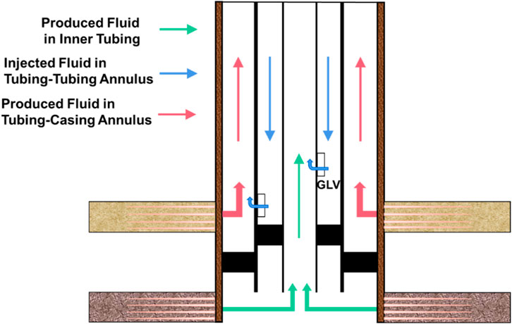
Figure 1. Schematic diagram of dual gas lift flow configuration.
In gas lift operations, temperature distribution within the wellbore plays a critical role in determining gas–liquid phase behavior, flow characteristics, and overall well productivity. The thermal resistance network method is a commonly used approach to model heat transfer processes. It treats the thermal system analogously to an electrical circuit, employing the concept of “thermal resistance” to calculate temperature distributions. This method is particularly suitable for modeling heat exchange in wellbores, where heat transfer paths are complex and involve multiple interfaces (e.g., fluids within the wellbore, tubing walls, annuli, and surrounding formation). In this analogy, temperature T corresponds to electric potential, heat flow rate Q to electric current, and thermal resistance R to electrical resistance. As illustrated in Figure 2, the dual gas lift deliquification process involves three principal flow channels: the inner tubing production path, the tubing–casing annular production path, and the tubing–tubing annular gas injection path. The thermal model must separately compute the heat transfer for each of these channels.
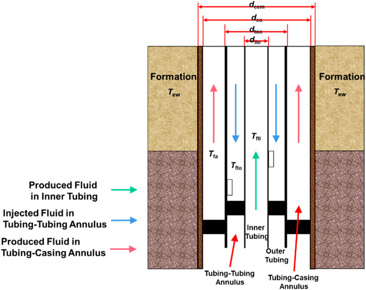
Figure 2. Schematic of radial heat loss between dual gas lift flow channels and surrounding formation.
The heat transfer for each channel can be expressed as:
Where: Qti, Qto and Qa denote the heat transfer rates (W) for the inner tubing, tubing–tubing annulus, and tubing–casing annulus, respectively; rtii, rtoi and rci are the inner diameters (m) of the inner tubing, outer tubing, and casing, respectively; Uti, Uto and Ua are the overall heat transfer coefficients (W/(m2·K)) for the inner tubing, tubing–tubing annulus, and tubing–casing annulus, respectively; Tew is the formation temperature (K); Tfti, Tfto and Tfa are the fluid temperatures (K) in the inner tubing, tubing–tubing annulus, and tubing–casing annulus, respectively.
Due to the unique wellbore structure and flow channel configuration of dual gas lift wells, the heat transfer process must account not only for the thermal resistance associated with heat exchange in the tubing–tubing annulus, but also for the individual heat transfer resistances and overall heat transfer coefficients of the three distinct flow channels: the inner tubing production path, the tubing–casing annular production path, and the tubing–tubing annular gas injection path. Based on the thermal resistance network method, the following computational procedure is proposed for modeling heat transfer in dual tubing wellbores.
(1) Calculation of environmental thermal resistance Rf
Environmental thermal resistance is unbounded and depends on the surrounding geological conditions. From the outer edge of the cement sheath to the formation, heat transfer is transient; thus, if the external environment of the wellbore is the geological formation, the environmental thermal resistance is governed by transient conductive heat transfer:
Where:
(2) The calculation of conductive thermal resistance from the formation to the casing R1 comprehensively considers the radial conductive resistances of both the casing wall and the cement sheath:
(3) The calculation of convective thermal resistance in the tubing–casing annulus R2 accounts for the convective heat transfer resistance between the fluid in the tubing–casing annulus and the inner surface of the casing:
(4) The calculation of thermal resistance in the tubing–tubing annulus R3 considers both the convective heat transfer resistance of the fluid within the tubing–tubing annulus and the radial conductive resistance of the outer tubing wall:
(5) The calculation of thermal resistance of the inner tubing R4 comprehensively considers both the convective heat transfer resistance of the fluid inside the inner tubing and the radial conductive resistance of the inner tubing wall:
(6) Computation of overall heat transfer coefficients for different flow paths:
For the tubing–casing annulus (production channel):
For the tubing–tubing annulus (gas injection channel):
For the inner tubing (production channel):
Where Rf, R1, R2, R3 and R4 are the environmental thermal resistance, formation-to-casing conduction resistance, tubing–casing annulus fluid resistance, tubing–tubing annulus fluid resistance, and inner tubing fluid resistance, respectively, in (m·K)/W; τD is the dimensionless Fourier number; αg is the thermal diffusivity of the formation, m2/s; t is cumulative production time, s;rcem, rco, rci, rtoo, rtoi, rtio and rtii represent the cement sheath radius, outer and inner diameters of casing, outer and inner diameters of the outer tubing, and outer and inner diameters of the inner tubing, respectively, in meters; λg, λc, λto, λti and λcemi are the thermal conductivities of formation, casing, outer tubing, inner tubing, and cement sheath, respectively, in W/(m·K); αfc, αfto and αft are the convective heat transfer coefficients for fluids in the tubing–casing annulus, tubing–tubing annulus, and inner tubing, respectively, in W/(m2·K).
Based on energy conservation, the differential equations for energy balance among the three flow channels—inner tubing, tubing–casing annulus, and tubing–tubing annulus—are formulated as follows:
Where Wa, Wto and Wti represent the mass flow rates or equivalent thermal capacities of the fluids in the tubing–casing annulus, tubing–tubing annulus, and inner tubing, respectively.
In the numerical solution, the wellbore is discretized into n segments, each of length L/n, where L is the total wellbore length. After establishing the difference equations and setting the convergence criteria, an iterative algorithm is used to calculate the temperature profile along the wellbore during gas well deliquification using dual gas lift.
3 Multiphase flow model for dual gas lift deliquification in dual-gas Co-production wells
To investigate the flow behavior within the multiple flow paths (inner tubing production channel, tubing-casing annulus production channel, and tubing-tubing annulus gas injection channel) of the dual gas lift deliquification system, this study modifies the Multiphase Flow Experimental Apparatus for Lifting Tubing with Complex Internal Boundaries to simulate annular gas-liquid flow under fixed internal boundary conditions. Utilizing the apparatus’s two-phase gas-liquid supply system and data acquisition system, key flow parameters are regulated and monitored under different gas-liquid ratios to capture and analyze flow pattern transitions. A DSLR camera is employed to visually record the flow patterns.
3.1 Physical experiment on dual gas lift multiphase flow
3.1.1 Experimental setup
The experiment is conducted at room temperature (15°C). The working media include tap water (density: 998 kg/m3, viscosity: 1.103 mPa·s) and air (density: 1.293 kg/m3, viscosity: 0.0183 mPa·s). The liquid flow range is 0–48 m3/d, and the gas flow range is 0–2500 m3/d. Transparent acrylic tubing is used to simulate the wellbore section for visual observation. The surface pipelines for two-phase flow are made of iron and connected via flanges to solenoid valves and other components to ensure sealing. A solid rod is installed at the top of the simulated tubing to model gas-liquid annular flow under fixed internal boundaries. The experimental procedure is shown in Figure 3, and the specific parameters of the experimental setup are listed in Table 1.
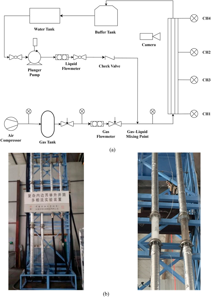
Figure 3. Experimental setup and procedure. (a) Experimental flowchart. (b) Multiphase flow apparatus with complex internal boundary.
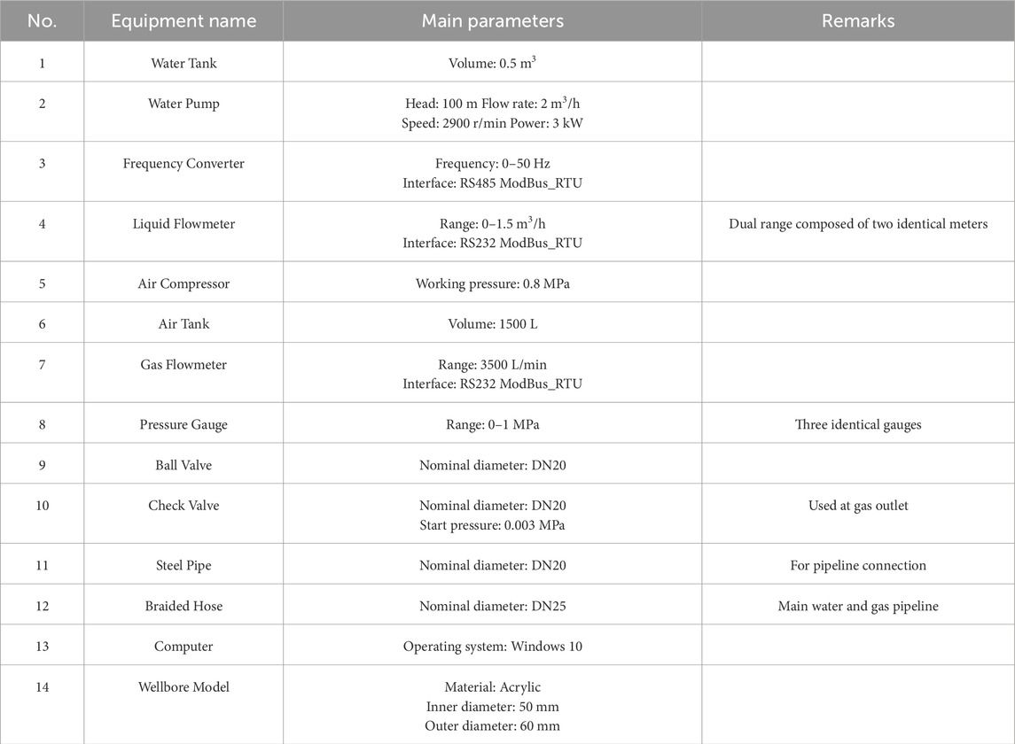
Table 1. Specific parameters of the experimental setup.
The main experimental steps are as follows:
(1) System setup and test run: Properly connect all equipment, open the valves, and start the plunger pump and air compressor. Adjust the pump frequency and gas flow for a trial run. Check for leaks or faults. If none, shut down and prepare for formal experiments.
(2) Initialization: Fix the internal boundary using the control system. Close the air compressor and gas loop valves, open the liquid flow valves, and adjust the plunger pump frequency to a desired fixed value.
(3) Baseline measurement: Once the water column is filled and the system is stable, gradually introduce gas at the minimum flow rate. After a steady two-phase flow is reached, record 30 s of data, including flow rates, pressure data, and images.
(4) Flow variation tests: Increase gas flow incrementally, recording data at each step while observing changes in flow pattern.
(5) Shutdown and repetition: Shut down the plunger pump and air compressor in sequence, close valves, and repeat steps (2)–(4) for further tests.
3.1.2 Multiphase flow in circular channel (inner tubing)
A transparent acrylic pipe with an inner diameter of 40 mm is used as the observation section, vertically mounted. Water is injected to form a liquid column, and air is gradually introduced through a regulator, as shown in Table 2. During the experiment, the flow pattern evolution is visually monitored, and gas-liquid flow rates and system pressures are recorded in real time.

Table 2. Experimental ranges for circular pipe multiphase flow.
The experimental design was developed based on the in-situ gas-liquid ratio of gas wells, and multiphase flow tests were conducted under various gas-liquid ratios. The resulting flow regimes and corresponding pressure variations are illustrated in Figure 4. When the gas volume within the wellbore is insufficient to lift the accumulated liquid to the surface, liquid loading occurs. In this case, the entrained liquid begins to fall back along the inner wall of the tubing to the well bottom, altering the flow regime within the wellbore. This change in flow pattern provides a practical basis for identifying the critical point of liquid loading, a concept referred to as the flow-pattern-based criterion for liquid loading. Research indicates that the transition from annular flow to slug flow is the principal cause of liquid accumulation in gas wells. At high gas velocities, both the central gas core and the annular liquid film move upward concurrently, enabling complete liquid lifting from the bottom of the well. Under these conditions, the dominant flow regime is annular flow. As the gas velocity decreases, the liquid film becomes increasingly unstable and begins to detach from the wall. The film thickens and eventually breaks into dispersed droplets within the gas core, increasing the effective mixture density. When the gas can no longer lift all the liquid to the surface, the flow regime transitions to slug flow. Therefore, the moment when the wellbore flow transitions from annular flow to slug flow defines the onset of liquid loading, and the corresponding gas velocity at this transition point is referred to as the critical gas velocity for liquid loading.

Figure 4. Flow patterns and pressure monitoring under different flow patterns in circular channels. (a) Slug flow. (b) Churn flow. (c) Annular-mist flow.
Based on pressure monitoring data from multiple measurement points, it was observed that as the superficial gas velocity increases, the flow regime evolves from slug flow to churn flow, and eventually to annular-mist flow. Throughout this transition, the liquid holdup within the wellbore decreases progressively, leading to a reduction in gravitational pressure drop and, consequently, a lower overall pressure gradient. Furthermore, the data reveal significant pressure fluctuations over time at the same measurement locations under both slug and churn flow conditions. This indicates that the flow under these regimes is inherently unstable and discontinuous. These findings highlight the necessity of optimizing multiphase flow models under high gas-liquid ratio conditions to better represent real wellbore dynamics and improve deliquification performance.
3.1.3 Multiphase flow experimental results and discussion in annular space (casing-tubing annulus production channel and tubing-tubing annulus gas injection channel)
During the experiment, the gas flow rate was varied while keeping the liquid flow rate constant in order to observe changes in flow regimes. As shown in Figure 5, a high-speed camera was used to capture flow patterns under different gas-liquid flow rate conditions. When the liquid flow rate was maintained at 0.86 m3/h and the gas flow rate was relatively low (less than 1.8 m3/h), the observed two-phase flow pattern in the experimental wellbore was bubble flow. As the gas ascended through the wellbore, the pressure within the system decreased, causing small bubbles to expand and coalesce. Larger bubbles were observed in the upper part of the wellbore, but due to the low gas flow rate, no distinct gas slugs were formed. When the gas flow rate ranged between 1.8 m3/h and 3.3 m3/h, the observed flow regime was a transitional flow—bullet flow. In this pattern, larger gas bubbles appeared more frequently, but their size was still insufficient to form well-defined gas slugs. As the gas flow rate continued to increase, the pressure within the wellbore further decreased from bottom to top. The increasing velocity of the small bubbles enhanced their coalescence probability, leading to the formation of larger gas bubbles. Although the frequency and size of large bubbles increased, they still did not evolve into fully developed gas slugs. When the gas flow rate exceeded 3.3 m3/h, the flow regime observed in the experimental wellbore transitioned to slug flow. At this stage, the increased gas velocity and gas-liquid ratio further enhanced bubble coalescence. Additionally, the gas volume expanded rapidly due to pressure reduction along the vertical axis of the wellbore, resulting in the formation of distinct slugs.

Figure 5. Flow patterns and pressure monitoring under different flow patterns in annular channels. (a) Bubble flow. (b) Bullet flow. (c) Slug flow.
Pressure data recorded under various gas-liquid flow conditions are shown in Figure 5. With a fixed liquid flow rate of 0.87 m3/h, the gas flow rate was adjusted to monitor pressure variations within the wellbore. When the gas flow rate was 1.2 m3/h and the internal boundary remained stationary, bubble flow was observed in the experimental setup. The pressure curves from the four measurement points were relatively smooth, indicating stable and uniform pressure conditions inside the wellbore, with no significant fluctuations. As the gas flow rate increased to 1.8 m3/h, the observed flow regime transitioned to slug-like flow. The pressure curves at the four monitoring points remained relatively smooth, and consistent trends were observed among pressure measurements at points CH1, CH2, and CH3. When the gas flow rate was further increased to 3.3 m3/h, slug flow was observed for the first time. At this point, the pressure curves recorded at all four measurement points exhibited significant fluctuations. Moreover, the pressure readings at CH1, CH2, and CH3 continued to show synchronized variation trends, highlighting the impact of the flow regime on wellbore pressure dynamics.
3.2 Multiphase flow model for inner tubing
Based on the production characteristics of the inner tubing in dual gas lift systems, and taking into account the applicable conditions considered during model development, several widely recognized multiphase flow models were preliminarily selected for comparison. These include models proposed by Ansari et al. (1994), Aziz and Govier (1972), Duns and Ros (1963), Beggs and Brill (1973). Pressure monitoring results at various measurement points under different gas-liquid ratio conditions were compared with the calculated results from the above models, as shown in Figure 6. The comparison revealed that the Beggs & Brill model provided the best fit with the experimental pressure data. Additionally, when comparing the flow pattern transition boundaries predicted by each model with the actual observed flow regime transitions, the Beggs & Brill model again demonstrated the closest match. Therefore, the Beggs & Brill model was selected as the optimal multiphase flow model for predicting flow behavior in the inner tubing of dual gas lift wells.
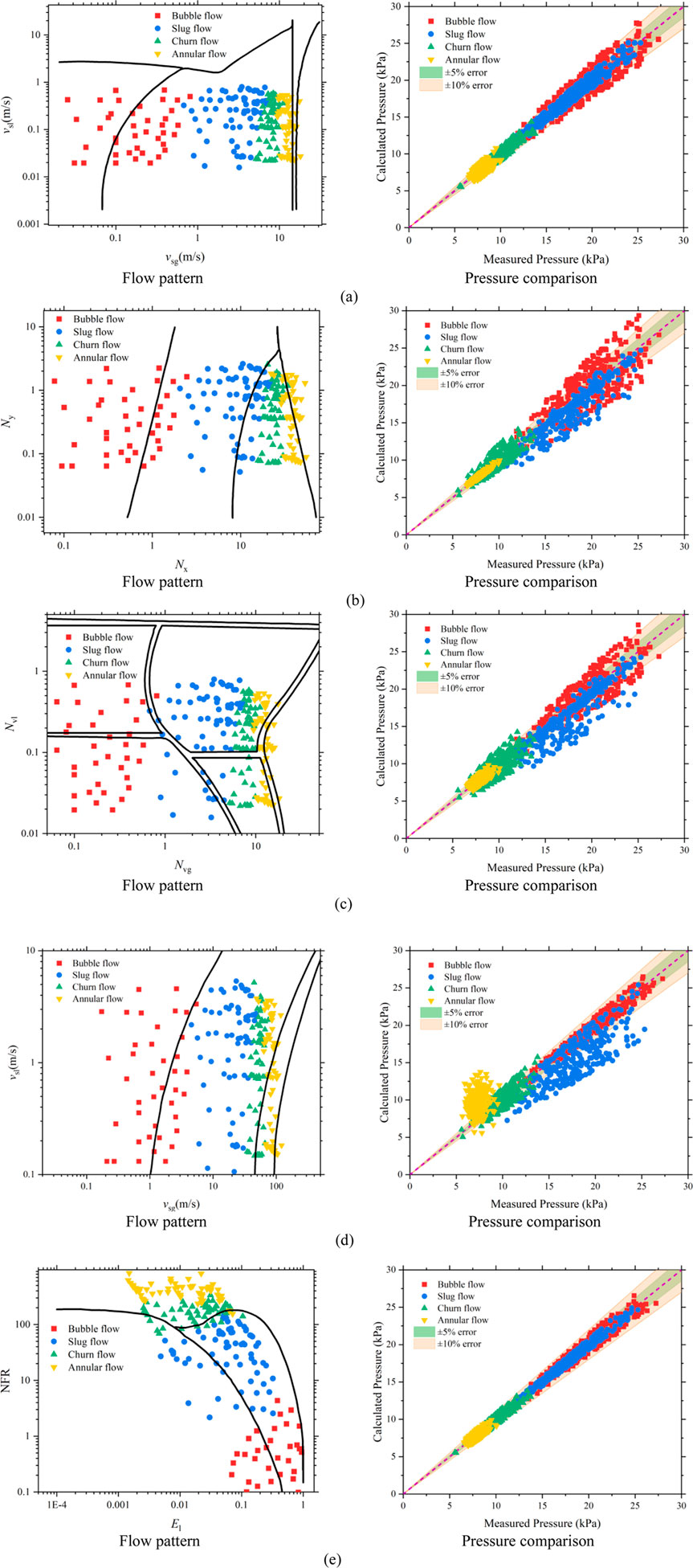
Figure 6. Model comparison for multiphase flow in inner tubing. (a) Ansari. (b) Aziz. (c) Gregory. (d) Duns & Ros. (e) Beggs & Brill.
3.3 Multiphase flow model for tubing-casing and tubing-tubing annulus
For the tubing-casing annulus and tubing-tubing annulus flow channels, the flow behavior falls under the category of annular space multiphase flow. To simulate gas-liquid two-phase flow in annular geometries, the Beggs & Brill model, originally developed for circular pipe flow, must be modified accordingly. The first adjustment involves the definition of an equivalent hydraulic radius, used to represent the effective diameter of the annular space:
Where
The relative roughness of the annular space must also be corrected using the following formulations:
Where kc, kto and kti are the absolute roughness of the casing, outer tubing, and inner tubing, respectively;
In the flow pattern map proposed by Kelessidis and Dukler (1989) for concentric annuli, slug flow is shown to evolve directly from bubbly flow, with no intermediate bullet flow regime. According to their definition, slug flow in annuli is characterized by Taylor bubbles that differ notably from those in circular pipes. While Taylor bubbles in circular pipes resemble symmetric bullet-shaped gas pockets spanning the full diameter, in annuli they form around the inner pipe, with downward-flowing liquid along the outer wall. These gas slugs are separated by liquid slugs that contain dispersed bubbles, resulting in a distinct flow structure. Based on Kelessidis & Dukler’s annular flow pattern map, this study proposes the following modifications:
(1) Transition from bubbly flow to bullet flow
At low liquid flow rates, gas bubbles rise in a meandering path and occasionally coalesce into large bubbles. When the void fraction in the cross-section reaches 0.25, the accumulation rate of large bubbles increases sharply, marking the transition to slug/bullet flow:
At higher liquid flow rates, turbulent forces break up large bubbles, leading to a dispersed bubble flow regime. In this case, transition to slug flow does not occur until the void fraction reaches 0.52:
(2) Transition from bullet flow to slug flow
In the annulus, a churn flow behavior similar to the inlet section of circular pipes can be observed. Slug flow gradually stabilizes downstream of bullet flow. Using the Taylor bubble catching model from Taitel and Dukler (1976), adapted for annular flow, the following transition criterion is obtained:
(3) Transition from slug flow to annular flow
This transition occurs when the void fraction in slug flow equals that in annular flow. For slug flow:
For annular flow:
where: vsl, vsg and vm are the superficial velocities of liquid, gas, and mixture (m/s); ρl and ρg are the liquid and gas densities (kg/m3); σ is the surface tension (N/m); Le is the slug initiation length (m); de is the equivalent hydraulic diameter of the annulus (m).
A flow pattern map based on experimental data was constructed using gas superficial velocity as the horizontal axis and liquid superficial velocity as the vertical axis, as shown in Figure 7.
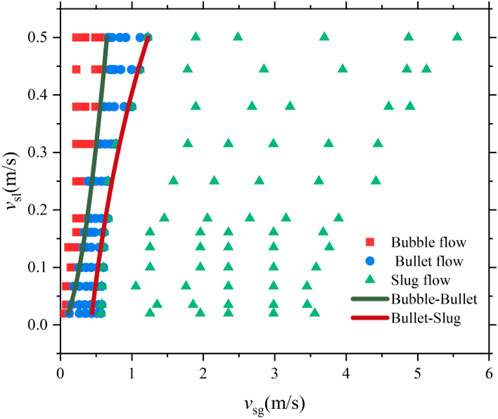
Figure 7. Flow pattern map for annular space multiphase flow.
The pressure drop in the annulus was analyzed using a differential control volume, accounting for gravitational, frictional, and acceleration pressure losses, as in conventional circular pipe models:
Considering that fluid flow in the tubing-casing annulus (production channel) is upward and in the tubing-tubing annulus (injection channel) is downward, the Beggs & Brill model was adopted for both cases, with appropriate modifications to flow regime classification, effective relative roughness, and equivalent flow area. The detailed computational procedure of the model is illustrated in Figure 8.
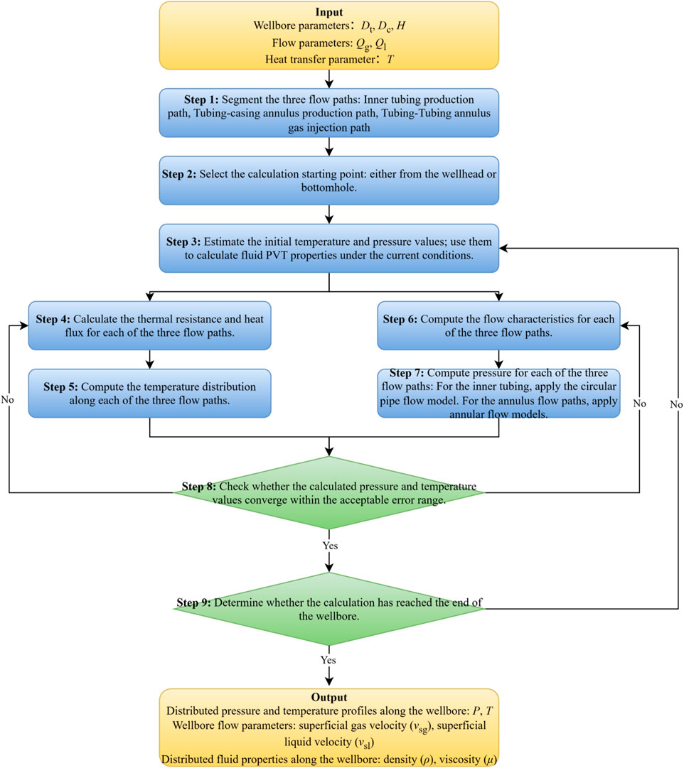
Figure 8. Computational flowchart.
The modified model was validated against experimental data obtained from a well with a depth of 12 m and an inner diameter of 40 mm, covering liquid flow rates from 0 to 48 m3/d and gas flow rates from 0 to 2500 m3/d. Comparison results, shown in Figure 9 and Table 3, demonstrate that the overall prediction accuracy of the model exceeds 90%. Among the different flow patterns, the model predicts bubbly flow with the highest average accuracy of 96.20%, while slug flow exhibits the lowest average accuracy at 94.37%.

Figure 9. Comparison between pressure drop model and experimental results.
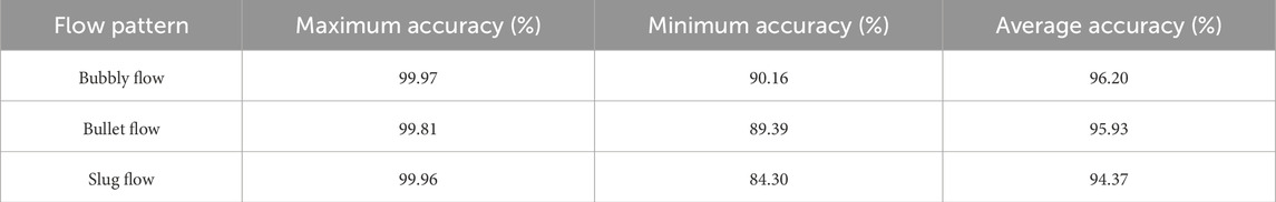
Table 3. Prediction accuracy for different flow pattern.
3.4 Gas lift valve and throttling models
Gas lift valves can be classified based on structural characteristics into orifice-type valves, bean-type valves, and Venturi-type valves. The orifice-type valve features a narrow flow passage with negligible thickness. The bean-type valve includes a longer narrow channel through which fluid must pass, while the Venturi valve is streamlined at both inlet and outlet ends, significantly reducing turbulence during throttling. Throttling valve models are generally established based on the conservation of mass and energy, and while assumptions vary across valve types, most models are fundamentally derived from the Bernoulli equation. The modeling process incorporates key effects such as gas-liquid slippage and gas expansion during throttling. The Bernoulli equation adapted for the throttling process is as follows:
At the narrowest section of the valve (the throat), fluid acceleration reaches a critical state. The critical velocity is computed as:
The entropy change during throttling is calculated by:
Temperature after throttling is given by:
During pressure drop, gas expansion occurs, and the expansion coefficient is defined as:
Due to the presence of inherent liquids and condensate in the production system, gas-liquid slip occurs during throttling. The slip ratio is calculated by:
Most throttling models are derived from the classical Gilbert gas lift choke model, which expresses flow rate as a function of upstream pressure, valve geometry, and gas-liquid ratio:
Where: Q is the flow rate through the valve (m3/s); Pup is the valve upstream pressure (Pa); dgv is the gas lift valve orifice diameter (m); GLR is the gas-liquid ratio (m3/m3).
According to this model, the post-throttling gas flow is primarily influenced by upstream pressure, valve diameter, and gas-liquid ratio. In this study, the empirical coefficients proposed by Achong et al. are adopted: a = 3.82,b = 0.65,c = 1.88.
4 Optimization design of dual gas lift with pressure-segregated dual-gas Co-production wells
A field well located in the Linxing–Shenfu block is selected for case study. This block is characterized by a stacked reservoir structure, consisting of an upper sandstone reservoir and a deeper coal seam. The upper sandstone reservoir is situated at a depth of 1,720 m with a thickness of 11.1 m, while the coal seam lies at 2172 m with a thickness of 4.08 m. Using the wellbore heat transfer model, pressure drop model, and gas lift valve throttling model presented earlier, and setting boundary conditions such as casing and tubing head pressure as well as reservoir pressures for the upper and lower zones, the pressure distribution profiles within each flow conduit of the wellbore are calculated under varying gas injection rates. The resulting pressure profiles are shown in Figure 10.

Figure 10. Pressure and temperature distribution profiles under different daily gas injection volumes. (a) 3 × 10⁴ m3/d. (b) 9 × 10⁴ m3/d. (c) 20 × 104 m3/d. (d) 40 × 104 m3/d. (e) 60 × 104 m3/d.
Based on varying gas injection volumes, the bottomhole flowing pressure, liquid production rate, and gas injection rate of each gas lift valve under different injection scenarios were determined, as shown in Figure 11. In this well, the lower reservoir is a coalbed methane reservoir, while the upper reservoir is a tight sandstone gas reservoir. During the initial production phase, as the daily gas injection rate increases, the bottomhole pressure of the coalbed methane reservoir first decreases and then slightly rises, indicating that the optimal injection rate at the wellhead is approximately 90,000 m3/day. In contrast, the bottomhole flowing pressure of the tight sandstone reservoir is relatively insensitive to injection rate due to its low water content and minimal liquid unloading requirement—meaning that changes in injection rate have little effect on the bottomhole liquid level. According to the established multiphase flow model for dual-tubing gas lift and the gas lift valve flow model, the calculated gas injection rate through the outer tubing is 4.33 × 10⁴ m3/day, and through the inner tubing is 4.67 × 10⁴ m3/day. The corresponding liquid production rates are 1.69 m3/day from the upper reservoir and 9.07 m3/day from the lower reservoir.
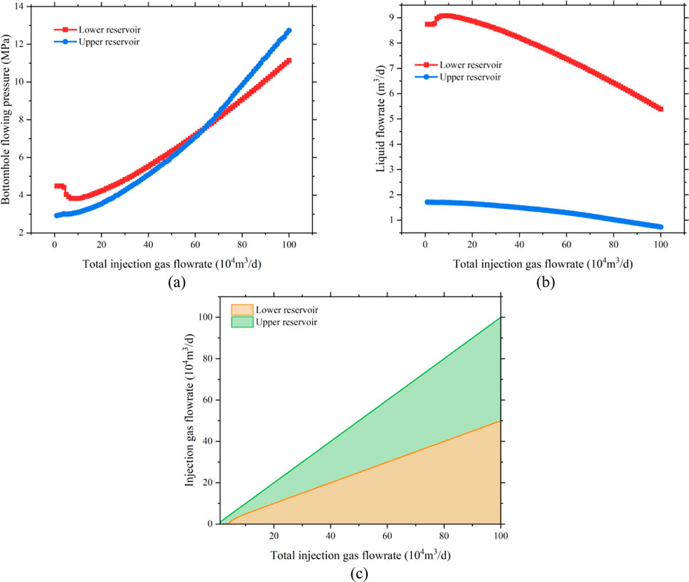
Figure 11. Relationship between bottomhole flowing pressure and liquid flowrate under different gas injection conditions. (a) Bottomhole flowing pressure. (b) Liquid flowrate. (c) Injection gas flowrate.
Based on the reservoir properties and production needs, and considering the response of BHFP in both reservoirs to injection rate, the production lifecycle of a dual-tubing, Dual-gas co-production wells can be divided into the following four stages:
(1) Startup and pressure control phase
Activate the small tubing system and initiate gas lift drainage for the lower coal seam via deep-set gas lift valves. This reduces bottomhole liquid level and reservoir pressure to promote gas desorption. Based on the BHFP-injection rate curve, the initial recommended gas injection rate is around 50,000 m3/day for optimal liquid removal.
(2) Stable co-production phase
The tight sandstone layer begins stable gas production, forming a dual-layer co-production system. The dual-tubing system is fully activated, with separate gas injection points controlling independent gas lift operations in the tubing and casing. The upper reservoir shows limited sensitivity to injection rate, so focus is placed on meeting the gas lift requirements of the lower coal seam.
(3) Decline and optimization phase
During this stage, production from the tight sandstone declines, while coal seam gas output remains stable or declines slightly. Gas injection into the upper reservoir can be reduced or operated intermittently to conserve energy, but negative pressure must be maintained in the coal seam to ensure effective deliquification.
(4) Low production phase
Gradually reduce gas injection into both reservoirs and transition to intermittent gas lift to recover residual gas. Gas lift in the upper reservoir (casing string) can be suspended, maintaining only the coal seam production system. Production continues until the economic limit or abandonment threshold is reached, as determined by cost-benefit evaluation.
A summary of the production strategies across the full lifecycle of the dual gas lift well is presented in Table 4.

Table 4. Production strategy for dual gas lift well across lifecycle.
5 Conclusion
In the context of co-production from tight gas and coalbed methane (CBM) within a single wellbore, the pressure regimes, gas–liquid ratios, and fluid properties of the overlying and underlying reservoirs differ significantly. Conventional gas lift methods struggle to effectively address the drainage and production requirements of both layers simultaneously. Owing to its multi-flow-path structure, the dual gas lift technique demonstrates superior adaptability to variable reservoir pressures and fluid characteristics, making it particularly advantageous for co-production of tight gas and CBM. This study focuses on the dual gas lift technology, establishing thermal loss models and multiphase flow models for the dual-tubing wellbore, and proposes an optimization strategy for pressure-segregated co-production. The key findings are as follows:
(1) A heat loss model for dual gas lift wellbores was developed. Compared with traditional models based solely on flow conduit geometry, this model incorporates the three-channel feature unique to dual gas lift systems: the inner tubing production path, the tubing–casing annulus production path, and the tubing–tubing annulus gas injection path. A dedicated heat transfer calculation method was introduced for the tubing–tubing annulus injection path, enhancing model fidelity.
(2) To investigate the flow behavior within the multiple flow conduits of the dual gas lift system, multiphase flow experiments were conducted using a “multiphase flow experimental setup for lift wells with complex internal boundaries.” The tests were carried out in both circular and annular flow spaces under controlled gas–liquid ratio conditions. Various flow parameters were measured, flow pattern transitions were observed, and a DSLR camera was employed for real-time visual recording of flow pattern.
(3) A multiphase flow model for dual-tubing gas lift wells was established, with separate modeling for the inner tubing production channel, the tubing–casing annulus production channel, and the tubing–tubing annulus injection channel. Based on experimental results, the Beggs & Brill model was selected as the optimal model for the inner tubing production path. For the annular flow paths, improved multiphase flow models were developed by modifying the Beggs & Brill framework to include refinements in flow regime classification, equivalent flow area, and pipe wall roughness. The models were validated against experimental pressure monitoring data, with pressure prediction accuracy exceeding 90% under all tested flow conditions.
(4) Based on the dual-tubing multiphase flow model and in consideration of reservoir characteristics and development objectives, the production lifecycle of dual gas lift wells for tight gas–CBM co-production was divided into four distinct phases: Startup and pressure control phase, Stable co-production phase, Decline and optimization phase and Late low-yield phase. Corresponding production strategies were proposed for each phase, ensuring the effective implementation of gas lift deliquification and production throughout the full lifecycle of co-production wells.
Data availability statement
The original contributions presented in the study are included in the article/supplementary material, further inquiries can be directed to the corresponding author.
Author contributions
YC: Writing – review and editing, Conceptualization. GW: Data curation, Project administration, Writing – review and editing, Supervision. ZL: Validation, Project administration, Writing – original draft, Writing – review and editing. JY: Writing – original draft, Supervision, Software, Methodology. MZ: Methodology, Supervision, Writing – review and editing.
Funding
The author(s) declare that no financial support was received for the research and/or publication of this article.
Conflict of interest
Authors YC, GW, ZL, JY, and MZ were employed by CNOOC Research Institute Ltd.
Generative AI statement
The author(s) declare that no Generative AI was used in the creation of this manuscript.
Publisher’s note
All claims expressed in this article are solely those of the authors and do not necessarily represent those of their affiliated organizations, or those of the publisher, the editors and the reviewers. Any product that may be evaluated in this article, or claim that may be made by its manufacturer, is not guaranteed or endorsed by the publisher.
References
Adepitan, A., Odedeyi, O., Osifo, F., Idehen, F., Oluwafemi, O., Aminat, A., et al. (2022). Modification of gas lift design in dual string producers using single point orifices in the niger delta. OnePetro. doi:10.2118/212037-MS
Ansari, A. M., Sylvester, N. D., Sarica, C., Shoham, O., and Brill, J. P. (1994). A comprehensive mechanistic model for upward two-phase flow in wellbores. SPE Prod. and Facil. 9 (02), 143–151. doi:10.2118/20630-PA
Ayers, W. B. (2002). Coalbed gas systems, resources, and production and a review of contrasting cases from the San Juan and powder river basins. AAPG Bull. 86 (11), 1853–1890. doi:10.1306/61EEDDAA-173E-11D7-8645000102C1865D
Aziz, K., and Govier, G. W. (1972). Pressure drop in Wells producing oil and gas. J. Can. Petroleum Technol. 11 (03). doi:10.2118/72-03-04
Bastian, P. A., Wirth, O. F. R., Wang, L., and Voneiff, G. W. (2024). Assessment and development of the dry horseshoe canyon CBM play in canada.
Beggs, D. H., and Brill, J. P. (1973). A study of two-phase flow in inclined pipes. J. Petroleum Technol. 25 (05), 607–617. doi:10.2118/4007-PA
Chen, S., Tang, D., Tao, S., Xu, H., Li, S., Zhao, J., et al. (2017). In-situ stress measurements and stress distribution characteristics of coal reservoirs in major coalfields in China: implication for coalbed methane (CBM) development. Int. J. Coal Geol. 182, 66–84. doi:10.1016/j.coal.2017.09.009
Colmenares, L. B., and Zoback, M. D. (2007). Hydraulic fracturing and wellbore completion of coalbed methane Wells in the powder river basin, Wyoming: implications for water and gas production. AAPG Bull. 91 (1), 51–67. doi:10.1306/07180605154
Emeka, O., Adeeyo, Y., Etim, A., Oluwalade, O., Ohabuike, O., Okene, U., et al. (2019). Retrofit gas lift deployment for oil production optimization in onshore niger Delta: a case study of EROTON E and P oil fields. OnePetro. doi:10.2118/198790-MS
Fu, H., Tang, D., Xu, H., Xu, T., Chen, B., Hu, P., et al. (2016). Geological characteristics and CBM exploration potential evaluation: a case study in the middle of the southern junggar basin, NW China. J. Nat. Gas Sci. Eng. 30, 557–570. doi:10.1016/j.jngse.2016.02.024
Gentzis, T., Goodarzi, F., Cheung, F. K., and Laggoun-Défarge, F. (2008). Coalbed methane producibility from the mannville coals in Alberta, Canada: a comparison of two areas. Int. J. Coal Geol. 74 (3), 237–249. doi:10.1016/j.coal.2008.01.004
Ghazali, M. H. M., Rozlan, M. R., Bakar, M. F., Ishak, M. F., Samuel, O. B., Misron, M. P., et al. (2021). World’S first successful dual string installation of a digital intelligent artificial lift DIAL - interventionless gas lift production optimization system, offshore malaysia. OnePetro. doi:10.2118/207819-MS
Hou, X., Liu, S., Zhu, Y., and Yang, Y. (2020). Evaluation of gas contents for a multi-seam deep coalbed methane reservoir and their geological controls: in situ direct method versus indirect method. Fuel 265, 116917. doi:10.1016/j.fuel.2019.116917
Johnson, R. C., and Flores, R. M. (1998). Developmental geology of coalbed methane from shallow to deep in rocky Mountain basins and in cook inlet–matanuska basin, Alaska, U.S.A. and Canada. Int. J. Coal Geol. 35 (1), 241–282. doi:10.1016/S0166-5162(97)00016-5
Karacan, C. Ö., and Okandan, E. (2000). Fracture/Cleat analysis of coals from Zonguldak basin (northwestern Turkey) relative to the potential of coalbed methane production. Int. J. Coal Geol. 44 (2), 109–125. doi:10.1016/S0166-5162(00)00004-5
Kelessidis, V. C., and Dukler, A. E. (1989). Modeling flow pattern transitions for upward gas-liquid flow in vertical concentric and eccentric annuli. Int. J. Multiph. Flow 15 (2), 173–191. doi:10.1016/0301-9322(89)90069-4
Law, C. C., Zainal, M. Z., Chew, K. H., and Lee, J. H. (2019). Hybrid model for determining dual string gas lift split factor in oil producers. Energies 12 (12), 2284. doi:10.3390/en12122284
Li, S., Tang, D., Pan, Z., Xu, H., Tao, S., Liu, Y., et al. (2018a). Geological conditions of deep coalbed methane in the eastern margin of the ordos basin, China: implications for coalbed methane development. J. Nat. Gas Sci. Eng. 53, 394–402. doi:10.1016/j.jngse.2018.03.016
Li, X., Fu, X., Yang, X., Ge, Y., and Quan, F. (2018b). Coalbed methane accumulation and dissipation patterns: a case study of the junggar basin, NW China. J. Asian Earth Sci. 160, 13–26. doi:10.1016/j.jseaes.2018.04.003
Li, S., Qin, Y., Tang, D., Shen, J., Wang, J., and Chen, S. (2023). A comprehensive review of deep coalbed methane and recent developments in China. Int. J. Coal Geol. 279, 104369. doi:10.1016/j.coal.2023.104369
Liu, A., Fu, X., Wang, K., and Wang, G. (2013). Investigation of coalbed methane potential in low-rank coal reservoirs – free and soluble gas contents. Fuel 112, 14–22. doi:10.1016/j.fuel.2013.05.032
Liu, D., Jia, Q., Cai, Y., Gao, C., Qiu, F., Zhao, Z., et al. (2022). A new insight into coalbed methane occurrence and accumulation in the qinshui basin, China. Gondwana Res. 111, 280–297. doi:10.1016/j.gr.2022.08.011
Misra, A., Gaurav, A., and Ranjan, A. (2024). Production stabilisation and enhancement in an offshore well using dual gas lifting in a single production string using modified gas lift set up. OnePetro. doi:10.4043/34907-MS
Moore, T. A. (2012). Coalbed methane: a review. Int. J. Coal Geol. 101, 36–81. doi:10.1016/j.coal.2012.05.011
Movahed, P., Burmaster, D., Karantinos, E., Villarreal, A. L., Memarzadeh, M., Vela, S. G., et al. (2024). Gas lift optimization in the Permian using machine learning and artificial intelligence. OnePetro. doi:10.2118/219553-MS
Olson, T., Hobbs, B., and Brooks, R. (2002). Paying off for tom brown in white river dome field’s tight sandstones, deep coals. Am. Oil Gas Rep. 10, 67–75.
Pashin, J. C., and McIntyre, M. R. (2003). Temperature–pressure conditions in coalbed methane reservoirs of the black warrior basin: implications for carbon sequestration and enhanced coalbed methane recovery. Int. J. Coal Geol. 54 (3), 167–183. doi:10.1016/S0166-5162(03)00034-X
Pillalamarry, M., Harpalani, S., and Liu, S. (2011). Gas diffusion behavior of coal and its impact on production from coalbed methane reservoirs. Int. J. Coal Geol. 86 (4), 342–348. doi:10.1016/j.coal.2011.03.007
Qin, Y., Moore, T. A., Shen, J., Yang, Z., Shen, Y., and Wang, G. (2018). Resources and geology of coalbed methane in China: a review. Int. Geol. Rev. 60 (5–6), 777–812. doi:10.1080/00206814.2017.1408034
Sajjad, F. M., Sastradinata, K., Rahmawati, S. D., Mansur, A., Wirawan, A., and Mujib, E. (2020). Gas lift robbing prevention in dual string completion using production pressure operating valve. OnePetro. doi:10.2118/196392-MS
Shen, J., Li, K., Zhang, H., Shabbiri, K., Hu, Q., and Zhang, C. (2021). The geochemical characteristics, origin, migration and accumulation modes of deep coal-measure gas in the west of linxing block at the eastern margin of ordos basin. J. Nat. Gas Sci. Eng. 91, 103965. doi:10.1016/j.jngse.2021.103965
Suggust, A. A., and Kueh, J. Z. (2023). Brilliant at the basics: a review on dual string gas lift injection performance in Malaysian offshore fields. OnePetro. doi:10.2523/IPTC-22806-MS
Taitel, Y., and Dukler, A. E. (1976). A model for predicting flow regime transitions in horizontal and near horizontal gas-liquid flow. AIChE J. 22 (1), 47–55. doi:10.1002/aic.690220105
Tang, S., Tang, D., Li, S., Xu, H., Tao, S., Geng, Y., et al. (2018). Fracture system identification of coal reservoir and the productivity differences of CBM Wells with different coal structures: a case in the yanchuannan block, ordos basin. J. Petroleum Sci. Eng. 161, 175–189. doi:10.1016/j.petrol.2017.11.048
Wang, L., Zhang, W., Cao, Z., Xue, Y., and Xiong, F. (2025). Coupled effects of the anisotropic permeability and adsorption-induced deformation on the hydrogen and carbon reservoir extraction dynamics. Phys. Fluids 37 (6). doi:10.1063/5.0270765
Xing, Z.-S., Han, G.-Q., Jia, Y.-L., Tian, W., Gong, H. F., Jiang, W. B., et al. (2025a). Optimization of plunger lift working systems using reinforcement learning for coupled wellbore/reservoir. Petroleum Sci. 22, 2154–2168. doi:10.1016/j.petsci.2025.03.009
Xing, Z., Han, G., Jia, Y., Tian, W., Gong, H., Zuo, H., et al. (2025b). Mechanistic modeling and experimental study of multistage plunger lift for liquid unloading in ultra-deep gas well. Geoenergy Sci. Eng. 246, 213653. doi:10.1016/j.geoen.2025.213653
Xu, P., Guo, Y., Ding, Y., Li, H., Chen, T., and Wang, H. (2025). Effect of polymeric aluminum chloride waste residue and citric acid on the properties of magnesium oxychloride cement. J. Build. Eng. 101, 111864. doi:10.1016/j.jobe.2025.111864
Zeinolabedini, L., Ameli, F., and Hemmati-Sarapardeh, A. (2025). Integration of artificial intelligence and advanced optimization techniques for continuous gas lift under restricted gas supply: a case study. Digit. Chem. Eng. 14, 100220. doi:10.1016/j.dche.2025.100220
Zhang, Y., Sun, B., Deng, Z., Chao, W., and Men, X. (2023). In situ stress distribution of deep coals and its influence on coalbed methane development in the shizhuang block, qinshui basin, China. ACS Omega 8 (39), 36188–36198. doi:10.1021/acsomega.3c04603
Keywords: dual-gas co-production, gas well liquid loading, gas well deliquification, dual gas lift, annular multiphase flow, deliquification optimization
Citation: Cao Y, Wu G, Li Z, Yu J and Zou M (2025) Multiphase flow modeling and optimization design method of dual gas lift for liquid unloading in dual-gas Co-production wells. Front. Earth Sci. 13:1650747. doi: 10.3389/feart.2025.1650747
Received: 20 June 2025; Accepted: 28 July 2025;
Published: 29 August 2025.
Edited by:
Xingyuan Liang, China University of Petroleum, ChinaReviewed by:
Zhengzheng Cao, Henan Polytechnic University, ChinaXiaojun Wu, Changzhou University, China
Mengjing Cao, Shandong Institute of Petroleum and Chemical Technology, China
Copyright © 2025 Cao, Wu, Li, Yu and Zou. This is an open-access article distributed under the terms of the Creative Commons Attribution License (CC BY). The use, distribution or reproduction in other forums is permitted, provided the original author(s) and the copyright owner(s) are credited and that the original publication in this journal is cited, in accordance with accepted academic practice. No use, distribution or reproduction is permitted which does not comply with these terms.
*Correspondence: Zhun Li, bGl6aHVuM0Bjbm9vYy5jb20uY24=