- 1China Coal Research Institute, Beijing, China
- 2State Key Laboratory of Hydroscience and Engineering, Tsinghua University, Beijing, China
- 3Jinneng Holding Equipment Manufacturing Group Co., Ltd., Jincheng, China
- 4China Coal Datong Energy Co., Ltd., Datong, China
Thick sandstone roof strata exacerbate surrounding rock deformation and failure in roadways, posing a severe threat to safe and efficient coal mine production. To address the challenge of controlling surrounding rock in high-stress roadways under such conditions, a novel composite roof cutting and pressure-relief method leveraging the dilation characteristics of gangue was hereby proposed. Firstly, numerical simulations were employed to establish a gangue model, and investigations were conducted into the in-fluence of gangue size and placement patterns on its dilation behavior and bearing capacity. The results revealed that within a specific size range (excluding extreme particle sizes such as the maximum and minimum), smaller gangue particles with more irregular placement exhibited a higher dilation coefficient and superior bearing performance. Building upon this principle, the composite roof cutting and pressure-relief method was further formulated, accompanied by the development of a theoretical roof structure model elucidating its control mechanism. Secondly, numerical simulations were performed to assess the control effectiveness of the new method, and comparative analyses were carried out to verify its efficacy. The results demonstrated that this method effectively utilized gangue dilation characteristics, significantly minimizing overlying strata subsidence and alleviating surrounding rock stress on the solid coal side of the roadway. Finally, field engineering trials were conducted. Monitoring data confirmed that the new method successfully reduced surrounding rock stress, optimized the roadway stress environment, effectively suppressed surrounding rock deformation, and achieved the objective of roadway protection. Overall, the re-search findings provide significant references for controlling surrounding rock deformation in high-stress roadways under thick sandstone roof conditions.
1 Introduction
China ranks as the world’s largest coal producer and consumer (Li J. K. et al., 2015; Wang et al., 2013a; Lin and Liu, 2010). While coal’s share in the primary energy consumption structure has declined in recent years, its dominance as the primary energy source is unlikely to be supplanted in the short term (Bai et al., 2018; Wang et al., 2013b). Ensuring safe and efficient coal mining is crucial for national energy security (Li et al., 2022; Zhang et al., 2022). In western China’s mining regions, thick coal seams are extensively distributed, frequently coupled with geological conditions characterized by hard roof strata (Qin et al., 2019; Chen et al., 2023). Mining under such conditions creates large goafs where the hard roof is reluctant to cave, giving rise to extensive suspended roof areas over the goaf (Wang B. et al., 2023; Wang Q. et al., 2023). The presence of such large-scale suspended roofs subjects the surrounding rock of underlying roadways to extremely high abutment pressures, readily inducing large deformations or even in-stability failures of the surrounding rock (Pan et al., 2022; Liu et al., 2021; Zhu et al., 2022), severely threatening mine safety (Zhang et al., 2024; Yan et al., 2020). Therefore, effectively controlling the stability of surrounding rock in high-stress roadways under thick coal seams with hard roof conditions remains a critical challenge for ensuring safe and efficient mining in these regions.
Current research on controlling roadway surrounding rock deformation primarily focuses on two key aspects: elucidating deformation mechanisms and developing control technologies. Regarding mechanistic studies, Li S. C. et al. (2015) carried out large-scale geo-mechanical model tests and revealed the deformation-failure mechanism of road-way surrounding rock. Moreover, they analyzed the displacement and stress evolution patterns and validated the primary failure characteristics through field comparisons. Lu et al. (2013), within an operational mine context, investigated the asymmetric deformation mechanism of deep soft rock roadways in fractured zones, uncovering that the orthogonal orientation between the roadway axis and maximum horizontal stress, combined with insufficient lateral constraints in inclined rock masses, induced a dominant deformation mode characterized by sidewall convergence and floor heave. They further elucidated the bending-squeezing mechanism within roadway clusters. Meng et al. (2023) delved into plastic zone radius and displacement deformation utilizing numerical simulation and field observation, supplemented by theoretical analysis. Their findings demonstrated that the coupling effect of high in-situ stress and mining-induced stress in deep soft rock roadways triggered plastic zone expansion, there-by leading to a synergistic deformation-failure mechanism involving roof sagging, sidewall deformation, and floor heave. Concerning support control, Wang et al. (2024) proposed an integrated “grouting pressure relief - inverted arch” support system to effectively manage deformation. The proposed system improved surrounding rock integrity through deep and shallow hole grouting, controlled plastic zone development by means of differential cable bolt loading, and actively mitigated floor heave via an inverted arch structure. Field applications verified its substantial effectiveness in restricting roadway deformation. Yang et al. (2018) adopted a closed high-strength support system combining flexible support (“bolt-cable-wire mesh”) with rigid full-section U-shaped steel support and an inverted arch floor. This configuration was selected to improve the stress state of surrounding rock, enhance the residual strength of shallow surrounding rock, and ultimately control deformation. Its effectiveness in significantly suppressing large deformations was validated through numerical simulation and field testing, offering a reference for deep roadway support. Zhang et al. (2023) employed control techniques including bolt (cable) support combined with grouting. Specifically, high-strength bolts (cables) and wire mesh were utilized to support the rock surface. Meanwhile, grouting reduced fractures and modified rock properties. Validation and guidance were achieved through an equivalent load model and UDEC (Universal Dis-tinct Element Code) simulation, enabling efficient control of surrounding rock deformation in roadways within thick, soft coal seams subjected to intensive mining-induced disturbances. However, practical experience indicates significant limitations in relying solely on enhanced support for roadways under high-stress conditions: this approach not only consumes substantial human, material, and financial resources (Xiang et al., 2021) but, more critically, support structures often fail to withstand massive destructive energy during large-scale roof weighting or sudden energy release (Hao et al., 2023), posing serious safety hazards and failing to address the root cause. Consequently, active pressure relief has emerged as an essential supplementary measure for controlling high-stress roadways (Zhao et al., 2025; Dang et al., 2024). Common pressure relief techniques include hydraulic fracturing and blasting. Regarding hydraulic fracturing, Zhang et al. (2025) employed prefabricated horizontal and vertical hydraulic fracturing techniques. This approach actively shortened the caving interval by creating vertical fractures to reduce the tensile strength of the hard roof, thereby facilitating the premature release of concentrated horizontal stress and mitigating the degree of vertical stress concentration during the bending and fracturing of overhanging strata. As a result, it effectively controlled the surrounding rock deformation in high-stress roadways. By establishing a critical stress model for floor buckling failure, Zhou et al. (2024) revealed the mechanisms of stress concentration and energy accumulation along the “roof-coal rib-floor” load transfer path. They implemented a combination of hydraulic fracturing-related techniques, including regional roof fracturing and abrasive waterjet roof cutting, alongside rib slotting and floor blasting. This targeted approach weakened both static and dynamic loads, effectively mitigating floor coal bursts and controlling surrounding rock deformation. In terms of blasting for pressure relief, Hu et al. (2020) proposed a synergistic control scheme primarily based on presplit blasting. By implementing presplit blasting to the roadway roof to disrupt its mechanical connection with the goaf and optimize stress distribution, this method effectively managed significant deformations in deep high-stress roadways without altering the original support conditions. Zhang et al. (2020) introduced directional roof presplitting (DRP) technology, which employed directional tensile blasting to generate smooth fracture planes in the roof. This technique enabled the goaf roof to cave and collapse along a preset trajectory, thereby actively releasing ac-cumulated stress. Field trials verified that this technology significantly reduced roadway convergence and controlled surrounding rock deformation. However, existing pressure relief methods exhibited notable shortcomings: hydraulic fracturing effectiveness was highly vulnerable to geological limitations and incurred relatively high costs; and traditional blasting-based pressure-relief approaches (e.g., simple loosening blasting) were often oversimplified, resulting in marginal efficacy (Fu et al., 2023). More critically, the uncontrollable nature of conventional blasting for pressure relief could readily in-duce new damage or even instability in the surrounding rock, thereby potentially compromising the overall stability of the roadway (Xu et al., 2025).
In summary, relying exclusively on enhanced support measures is not only costly but also frequently inadequate against sudden high-energy failures, as these measures merely address surface symptoms rather than underlying causes. Existing pressure relief techniques are either limited in effectiveness or exposed to risks such as poor controllability and potential damage to the surrounding rock. Consequently, there is an urgent need to explore a new pressure relief technology that is more effective, more controllable, and capable of fundamentally alleviating high stress in roadway sur-rounding rock. To address the core challenges of large suspended roof areas above the goaf and the harsh stress environment in roadways under thick coal seams with hard roof conditions, this study innovatively proposed a novel composite roof cutting and pressure relief method, leveraging the fragmentation-expansion characteristics of gangue. The core principle of this method involved: (1) utilizing directional energy-concentrated roof cutting to precisely sever the key roof strata, creating predetermined cutting lines to control the caving morphology; and (2) employing non-directional roof cutting to fully fragment the roof strata within the designated caving zone, thereby leveraging the fragmentation-expansion property of the broken gangue to rapidly and effectively fill the caving space within the goaf. Through the synergistic application of these two roof cutting techniques, the method was designed to actively induce on-demand and timely roof caving. The fragmented and expanded gangue mass then provided support, effectively mitigating the abutment pressure transferred to the roadway while fundamentally improving the stress state of the sur-rounding rock. Overall, this research provides a novel approach to solving the challenging problem of surrounding rock control in roadways under thick coal seams with hard roofs, offering valuable reference significance for ensuring the safety and stability of roadways under similar geological conditions.
2 Study on fragmentation-induced bulking and bearing behavior
2.1 Model construction
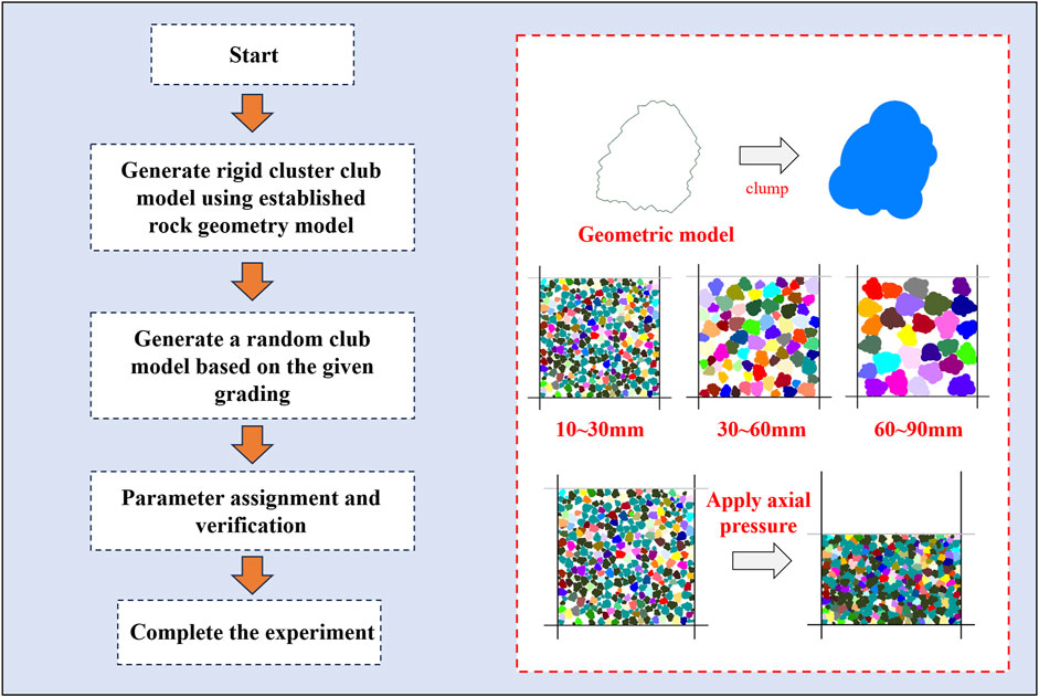
To establish the model using the PFC discrete element software, gangue block models were initially generated. For the better simulation of characteristics such as bulking, sliding, and rotation of gangue during the loading process, irregular blocks, rather than circular or elliptical models, were utilized for the equivalent representation of gangue. The relevant research was conducted using the PFC2D numerical simulation software, involving the following three key steps: establishing the initial model, generating gangue blocks, and calibrating parameters through experiments. The overall workflow is illustrated in Figure 1.
(1) Establishing the initial model: Prior to conducting the numerical simulation of the gangue compression experiment, the particle size distribution of the gangue for the numerical test and the dimensions of the rectangular confinement walls should be initially defined.
(2) Generating the gangue block model: Rigid clusters, representing irregular blocks, were formed by overlapping multiple pebble particle elements. The pre-defined gangue geometry was imported using the geometry import command, and rigid clump models were subsequently generated. The radii defining the gangue particle outlines conformed to a uniform distribution ranging from Rmin to Rmax.
(3) Parameter calibration and testing: The generated gangue model was assigned material properties corresponding to its mechanical characteristics. Subsequently, numerical simulations were performed to investigate gangue fragmentation-expansion behavior and the size effect on its load-bearing capacity.
2.2 Mesoscopic parameter determination
The mesoscopic parameters of the bonded-particle model were calibrated through an iterative process. The boundary conditions and loading protocol of the laboratory compressive test on fragmented rock were fully replicated in the numerical simulation. The resulting stress-strain curve from the simulation was systematically compared with the experimental data obtained from the laboratory tests. The mesoscopic parameters were then iteratively adjusted until the numerical results converged satisfactorily with the experimental measurements. Table 1 presents the finalized parameters selected through this calibration process.
2.3 Study on the size effect of fragmentation-expansion
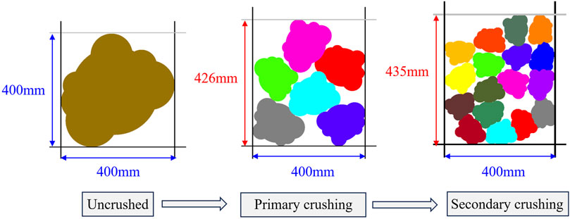
To investigate the fragmentation-expansion size effect, an irregular gangue block was placed within a 400 mm × 400 mm model, as illustrated in Figure 2. Subsequently, the gangue was crushed and backfilled into the same model, where the occupied area measured 400 mm × 426 mm. This demonstrated an increase in the total area occupied by the gangue fragments compared to the intact block. Further crushing of the gangue fragments resulted in an occupied area of 400 mm × 435 mm. The above analysis indicated that the void ratio was the primary factor governing the area occupied by crushed gangue. Upon crushing, the increased number of individual fragments prevented the tight interlocking observed in the original monolithic state, inevitably creating voids. While the overall cross-sectional area of the gangue mass remained constant, a higher void ratio resulted in greater spatial occupancy. Consequently, this study revealed that appropriately reducing the particle size of gangue could enhance the void ratio, thereby effectively increasing the fragmentation-expansion coefficient.
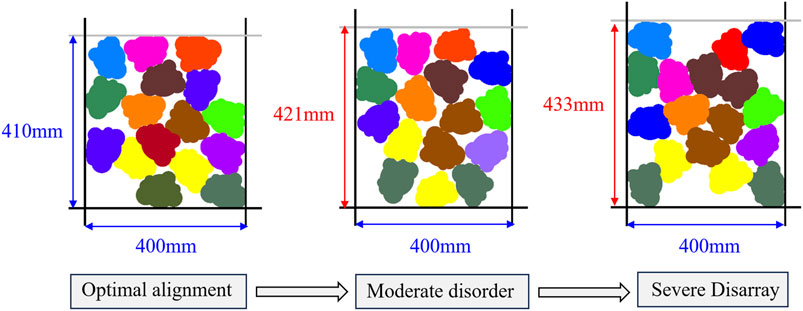
Simultaneously, the above analysis indicated that the void ratio was the primary factor governing the fragmentation-expansion coefficient of gangue. In addition to increasing the void ratio by reducing particle size, the arrangement pattern of crushed gangue also had a significant impact on its void ratio. As shown in Figure 3, when the same batch of crushed gangue was placed within the model using different arrangement methods, variations in the occupied area were observed. When arranged in an orderly manner, the gangue measured 400 mm × 410 mm. When arranged with moderate disorder, the occupied area increased to 400 mm × 421 mm. Further reducing the arrangement regularity to achieve a severe disordered state resulted in a continued area increase to 400 mm × 433 mm. Consequently, this study demonstrated that reducing the regularity of gangue placement could increase the void ratio, thereby effectively enhancing the bulking coefficient.
The above investigations into the fragmentation-expansion size effect of gangue uncovered that under specific conditions, reducing the particle size and decreasing the arrangement regularity of gangue could effectively enhance the fragmentation-expansion coefficient.
2.4 Study on bearing size effect
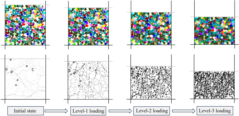
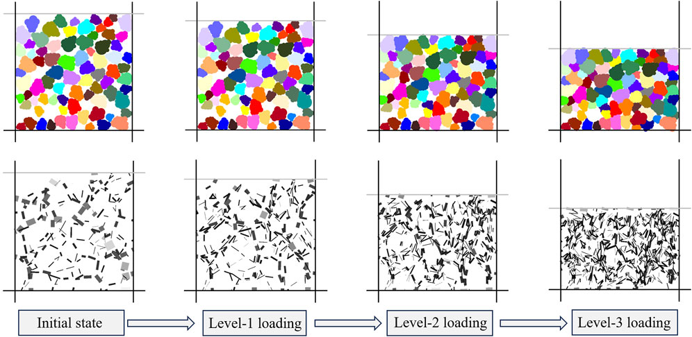
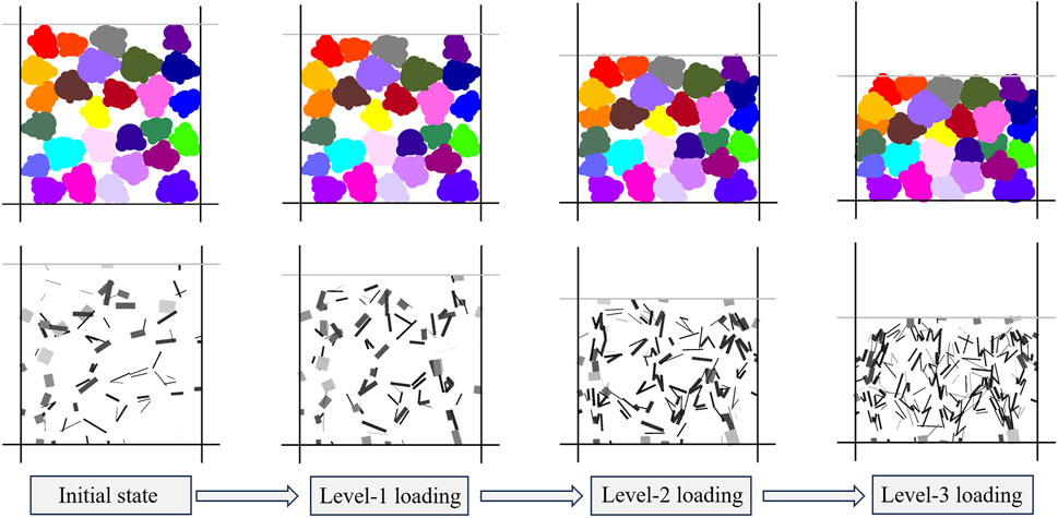
In practical engineering, upon completion of longwall mining, the immediate roof collapses into the goaf. Under the load of overlying strata, the collapsed gangue undergoes compressive deformation, and its load-bearing and compression properties are critical for controlling overlying strata movement. Consequently, investigating the compression behavior of gangue holds considerable importance. Herein, to elucidate the evolution of mesoscopic contact force chains between gangue particles during compaction with varying grain sizes, uniaxial confined compression tests were conducted. The test specimens comprised three groups with particle size ranges of 10–30 mm, 30–60 mm, and 60–90 mm, and a rectangular confinement chamber with dimensions of 400 mm × 400 mm was designed for the experiments. Through simulated uniaxial confined compression tests, graded compression was applied to the three gangue size groups. Particle cluster distributions and force chain networks at each loading stage were obtained, as illustrated in Figures 4–6.
By analyzing force chain evolution during compression, the transmission paths of compressive forces could be determined. Simultaneously, the magnitude of transmitted forces could be quantified based on force chain thickness. As depicted in Figures 4–6, particle cluster distributions and force chain networks experienced two distinct stages throughout the compression process. During the transition from the initial state to level-1 loading, neither force chain density nor thickness exhibited notable changes across all three particle size groups, suggesting a void compaction stage. Conversely, from level-1 to level-1 loading, both force chain density and thickness demonstrated distinctive increases for all particle sizes. Consequently, this phase was identified as the gangue bearing stage.
Comparative analysis of particle clusters and force chain morphologies under three distinct particle size ranges revealed coarser skeletal force chain structures of gangue in the 30–60 mm and 60–90 mm cohorts, compared to the 10–30 mm group. This indicated a pronounced skeletal bearing effect during compressive deformation of larger-sized gangue. Simultaneously, the 10–30 mm gangue developed a more uniform and intricate force chain network relative to the 30–60 mm and 60–90 mm groups. This phenomenon was most evident during the load-bearing stage, where force chains exhibited homogeneous complexity, indicating that smaller particles possess enhanced structural stability and load-bearing capacity. Conversely, force chains in the 30–60 mm and 60–90 mm cohorts displayed non-uniform distribution and structural simplification during their bearing stages. Consequently, smaller-sized gangue achieved higher force chain density, diversified force transmission pathways, and homogeneous network architecture. This resulted in uniform stress distribution and superior bearing stability throughout the granular assembly.
3 Composite roof cutting and pressure relief methods
3.1 Directional roof cutting methods
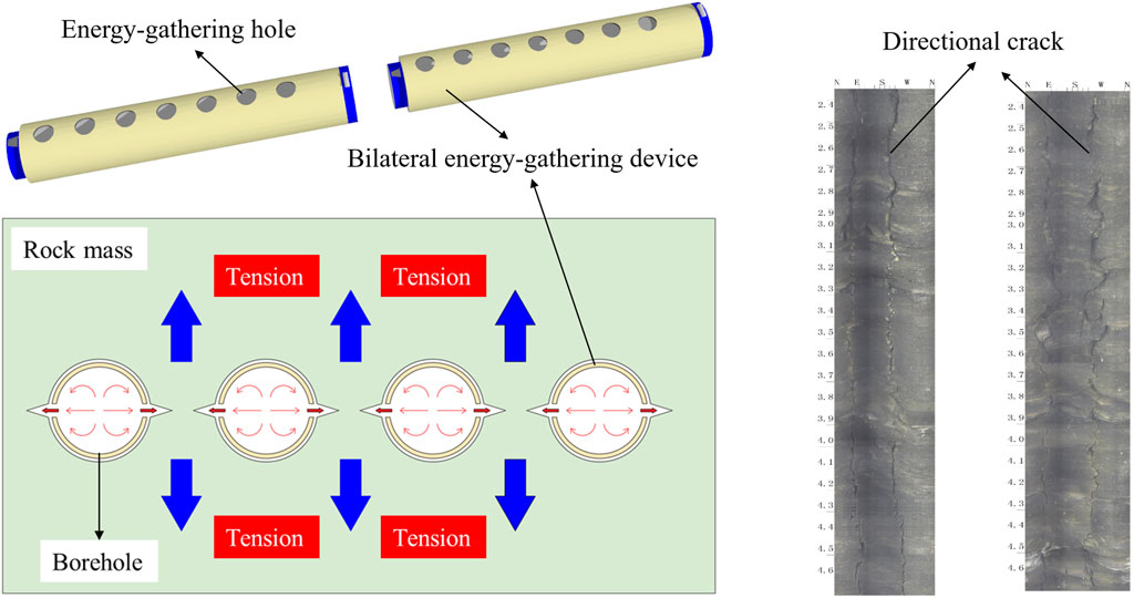
By exploiting rock’s characteristic of high compressive strength but low tensile strength, a directional roof cutting technique with controlled crack propagation was developed. The core innovation lies in an energy-concentrating device: a tubular structure with symmetrically arranged energy-concentrating holes on both sides. Upon detonation of explosives loaded within this device emplaced in boreholes, concentrated energy jets propagated radially through the pre-oriented holes, fracturing the rock. Cracks subsequently extended along the predetermined hole alignment, achieving controlled rock segmentation along the designated plane. To validate the technique efficacy, field trials implemented directional roof cutting with post-blast assessment via borehole inspection cameras. Inspection results confirmed exclusive fracture development along energy-concentrating hole orientations, with no peripheral cracking observed. Figure 7 details the energy-concentrating device design, underlying physics, and experimental roof cutting outcomes.
3.2 Composite roof cutting and pressure relief method
The roof cutting and pressure relief method employed directional roof cutting to segment long cantilever beams into short beams, thereby severing stress transfer pathways between the goaf roof and roadway roof. This mechanism effectively reduced surrounding rock stress in roadways. Based on the above findings about the fragmentation-expansion and bearing size effects of gangue, reducing the particle size of collapsed gangue-thereby inducing more disordered particle arrangements-could enhance the fragmentation-expansion coefficient. This promoted complete goaf backfill, subsequently minimizing overlying strata subsidence and roadway rock stress. Consequently, the synergistic integration of non-directional and directional roof cutting merged pressure-relief effects with gangue fragmentation-expansion mechanisms, enabling superior control of roadway surrounding rock stress. This dual-technique approach, comprising directional and non-directional roof cutting, was hereby defined as the Composite Roof Cutting and Pressure Relief Method. Its technical principle is illustrated in Figure 8.
4 Control mechanisms
4.1 Mechanical analysis of roof structure
4.1.1 Initial surrounding rock mass structure
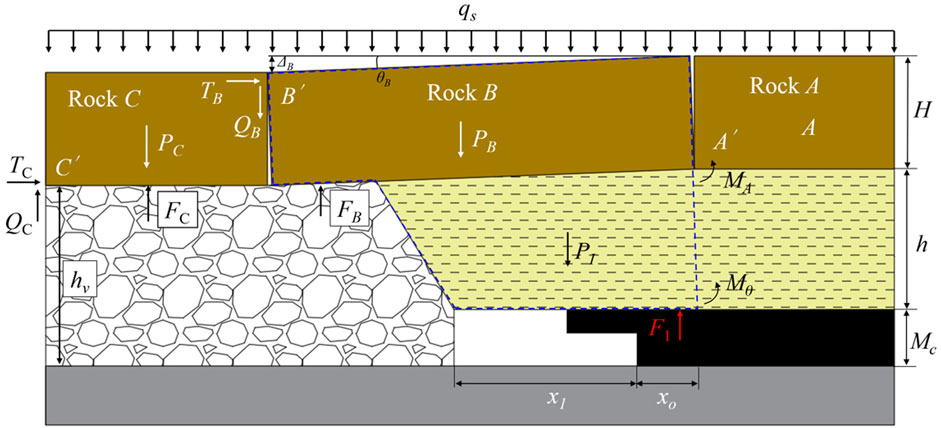
With advancing longwall face, the mechanical model of the goaf roof strata structure is illustrated in Figure 9.
Following the collapse of the immediate roof strata, fragmentation-expansion occurred in the goaf gangue, resulting in a compacted height hv exceeding the original thickness h of the immediate roof. This phenomenon, termed the fragmentation-expansion characteristic of gangue, was quantified by the bulking coefficient KP. However, as the main roof comprises thick-hard sandstone, the immediate roof resisted collapse, creating unfilled cavities within the goaf that failed to provide effective support for overlying strata. Consequently, the main roof fractured into discrete rock blocks connected via articulated joints for load transfer.
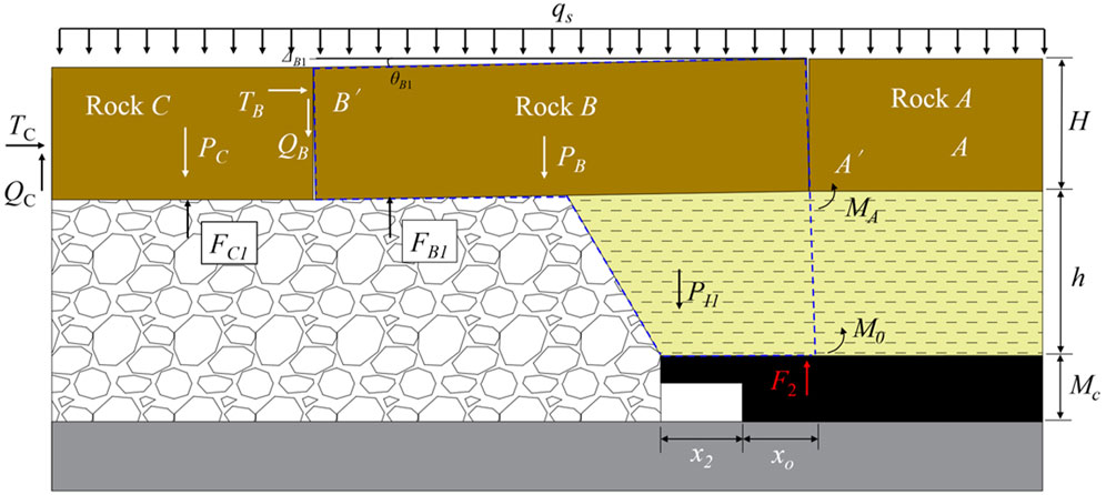
TC: Horizontal thrust at contact point C′ of block C.
QC: Shear force at point C′ of block C.
PC: Self-weight of block C.
FC: Gangue support force from goaf.
LC: Length of block C.
PI: Self-weight of immediate roof.
MA: Bending moment at point A′ of block A.
M0: Flexural resistance moment of immediate roof.
F1: Support force from solid coal.
Furthermore, key block B above the roadway fractured at the interface between plastic and elastic zones of the solid coal. Under overburden pressure qs, it underwent rotational subsidence, with subsidence magnitude ΔB and rotation angle θB respectively expressed as:
where Mc is the coal seam thickness, m; and h is the immediate roof thickness, m.
4.1.2 Directional roof cutting technology rock mass structure
Upon applying directional roof cutting technology to the roof on the goaf side of the roadway, the mechanical model of the goaf roof structure is shown in Figure 10. Compared to the original surrounding rock structure, the caving range of the immediate roof expanded, filling the unfilled space in the headgate area of the working face. Consequently, the goaf waste rock also provided a supporting force (FB) to the fractured rock block B. Simultaneously, the height hv of the accumulated waste rock in the goaf increased accordingly. However, due to the roof strata being composed of hard-thick sandstone, the collapsed waste rock fragments were relatively large and compactly arranged. This resulted in a very small fragmentation-expansion factor Kp, preventing the waste rock from completely filling the goaf. Consequently, the supporting force exerted by the goaf waste rock on rock block C, FC1, was greater than FC (FC1 > FC). Additionally, the subsidence amount ΔB and rotation angle θB of fractured rock block B decreased compared to those in the original surrounding rock structure.
4.1.3 Composite roof cutting and pressure relief technology rock mass structure
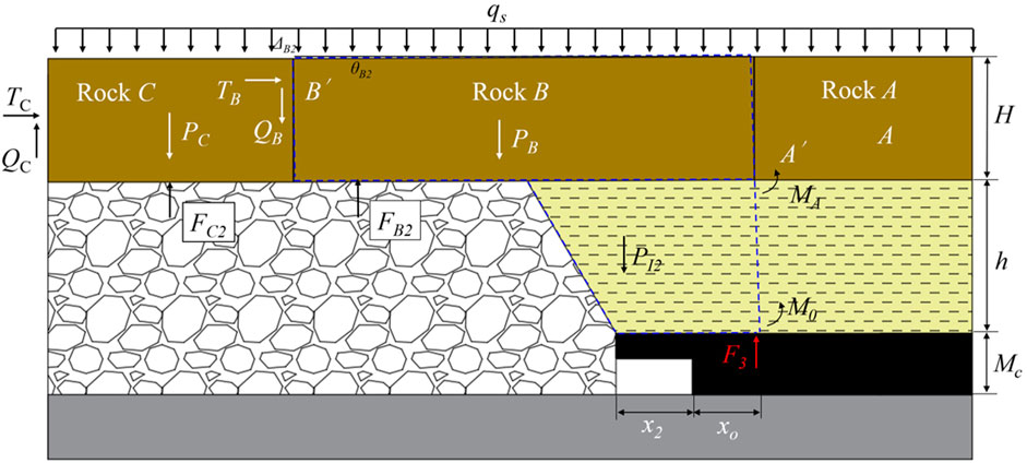
Upon applying both directional roof cutting technology and non-directional roof cutting technology to the roof on the goaf side of the roadway, the mechanical model of the goaf roof structure is shown in Figure 11. The non-directional roof cutting technology reduced the size of the caved waste rock fragments while disrupting their arrangement, thereby increasing the bulking factor KP of the waste rock. Consequently, the accumulated height hv of the waste rock in the goaf further increased, completely filling the goaf and providing enhanced support to the overlying main roof strata. Therefore, the supporting forces in the goaf satisfied FC2 > FC1 and FB2 > FB1. Furthermore, the subsidence amount ΔB2 > ΔB1 and rotation angle θB2 > θB1 of fractured rock block B increased compared to the previous state.
4.2 Comparative analysis of roof cutting and pressure relief mechanisms
Mechanical equilibrium analysis of fractured rock blocks C and B in three types of surrounding rock structures was conducted with the following assumptions: (1) The key stratum exhibited negligible internal deformation and was treated as a rigid body. The weight of overlying strata above the main roof (incapable of forming a stable voussoir beam structure) was uniformly distributed on the key stratum. (2) The effects of the fracture angle on the goaf side and the cutting angle in the immediate roof were excluded from consideration. (3) The support force provided by the solid coal was considered a concentrated force acting at the rib side position x0/3, with x0 serving as the length of the plastic zone in the supporting coal body.
For rock block C in the original model,
Therefore, QB can be determined as:
For rock block B, by applying
Combining Equations 1–3, subjected to a horizontal lateral thrust in.
Combining Equations 4–6, we obtain F1 as:
Similarly, the coal mass support force F2 after adopting directional roof cutting technology is obtained as:
Analysis of the unloading effect induced by directional roof cutting technology:
As clearly demonstrated by Equations 7–9, the total support force F1 exceeded that of F2. This indicated that directional roof cutting technology effectively enhanced the bulking capacity of goaf debris, restricted rotational subsidence movements of fractured rock blocks, reduced transmitted loads from overlying strata, and ensured the holistic stability of solid coal ribs in roadways.
Following the identical methodology, the coal mass support force F3 after implementing composite roof cutting technology (CRC) could be derived as:
Comparative analysis of pressure-relief effectiveness between directional and composite roof cutting technologies was conducted as:
As obviously evidenced by Equations 10, 11, the total support force F2 exceeded that of F3. This demonstrated that composite roof cutting technology (CRC) fully mobilized the bearing capacity of goaf debris, effectively reduced mining-induced pressure on solid coal masses, and thereby established self-equilibrium in near-field surrounding rock.
5 Control effectiveness
5.1 Model establishment
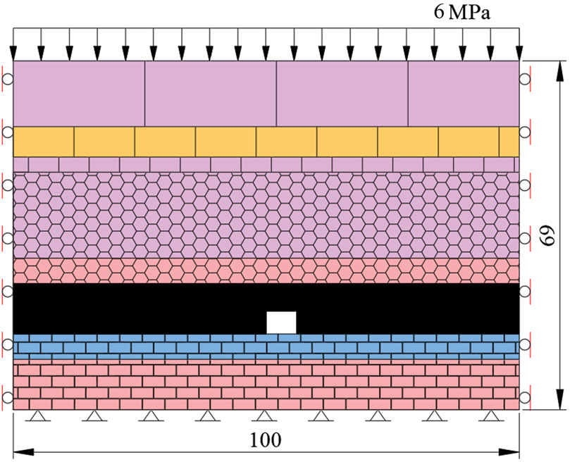
Numerical models for the scenarios of uncut roof, directional roof cutting, and compound roof cutting were established using the UDEC discrete element software, as illustrated in Figure 12. The model dimensions were 100 m in length × 69 m in height. A uniformly distributed load of 6 MPa was applied to the upper boundary, with displacement-controlled boundaries specified for the bottom and lateral boundaries. To simulate the natural failure and collapse process of the immediate roof, the Voronoi Tessellation Generator was employed to create polygonal blocks with randomized sizes. The rock blocks were simulated using the Mohr-Coulomb constitutive model, and the Coulomb slip constitutive model was adopted for the joint interfaces. Directional blasting holes measure 32 m in depth with a 60° dip angle, while non-directional blasting holes are 33 m deep at a 50° dip angle. Table 2 summarize the final parameters utilized in the numerical simulations.
5.2 Analysis of control effectiveness
Following the numerical simulations, the roof collapse patterns for the intact roof, directional roof cutting, and compound roof cutting methods are depicted in Figure 13. In the intact roof scenario (Figure 13a), a significant long cantilever beam persisted in the gob-side roof. Roof collapse was incomplete, and the resulting collapsed gangue proved insufficient to provide support for the overlying gob roof. Consequently, severe deformation and damage occurred in the surrounding rock of the roadway. Under the directional roof cutting method (Figure 13b), the gob roof fractured along the pre-designed cutting line, effectively segmenting the long cantilever into shorter beams. However, the volume of collapsed gangue remained inadequate to completely fill the gob area, thus failing to furnish effective support for the gob roof. Notably, deformation and damage in the roadway surrounding rock were improved compared to the intact condition. With the compound roof cutting method (Figure 13c), directional roof cutting effectively fragmented the long cantilever beam into shorter segments. Simultaneously, the action of non-directional roof cutting induced sufficiently complete roof collapse within the gob area. The resulting collapsed gangue fully filled the gob, thereby providing effective filling support to the overlying gob roof. Consequently, deformation and damage in the roadway surrounding rock were substantially improved.
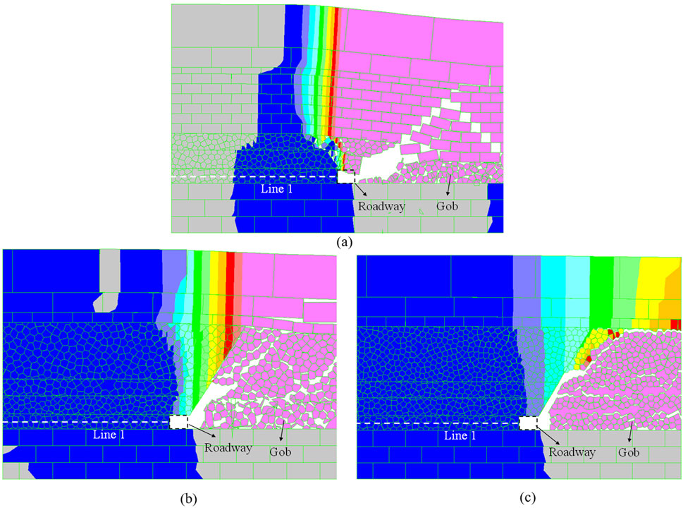
Figure 13. Illustrates the roof collapse patterns under the different methods: (a) Uncut roof; (b) Directional roof cutting; (c) Compound roof cutting.
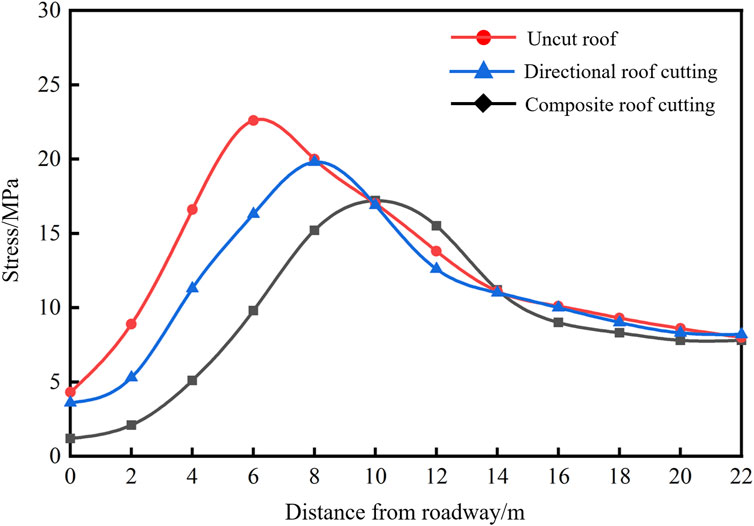
Building upon the understanding of these collapse morphologies, stress distribution within the solid coal side was monitored along Survey Line 1 for all three scenarios. The monitoring results are presented in Figure 14. Under the intact roof condition, the peak stress reached 22.6 MPa, located 6 m from the roadway rib. The application of the directional roof cutting method decreased the peak stress to 19.8 MPa, representing a 12.4% reduction compared to the intact roof scenario. Furthermore, the peak stress shifted away from the roadway, locating at 8 m from the rib. Under the compound roof cutting method, the peak stress further decreased to 17.2 MPa, representing a 23.9% reduction compared to the intact roof and a 13.1% reduction relative to the directional roof cutting method. Meanwhile, the peak stress location continued to migrate away from the roadway, now situated 10 m from the rib.
The numerical simulation results demonstrated that the compound roof cutting method exhibited pronounced advantages over both the uncut roof and directional roof cutting methods in controlling the stope surrounding rock structure and regulating the stress state of the roadway surrounding rock. The compound roof cutting method employed a dual-mechanism approach: (1) Directional roof cutting artificially controlled the fracture location within the gob roof, inducing roof breakage precisely along the pre-designed cutting line. This severed the cantilever beam into shorter segments, achieving pressure relief through controlled roof fracturing. (2) Concurrent non-directional roof cutting ensured thorough collapse of the gob roof, significantly enhancing the bulking factor of fragmented gangue to fully fill the gob void. The expanded gangue volume thereby provided effective support to the overlying roof strata through bulking-induced filling. The synergistic effect of these mechanisms substantially reduced stress concentrations in the roadway surrounding rock, optimizing the roadway stress environment and ultimately alleviating roadway deformation.
6 Field engineering test
6.1 Scheme design
6.1.1 Trial panel and scheme
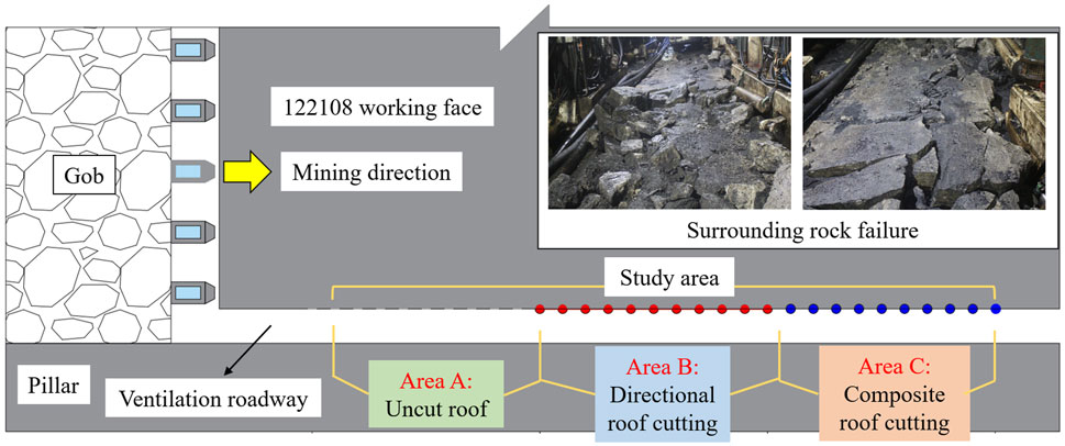
The field engineering trial was conducted at Panel 122,108 of Caojiatan Coal Mine in Yulin, Shaanxi, China, featuring a 280 m dip length and 5,910 m strike length with an average coal thickness of 10.25 m and dip angle of 0°–5°. Top-coal caving methodology was employed, involving a 5.8 m cutting height and 5–6 m caving height. The seam exhibited simple structure, stratigraphically comprising fine-grained sandstone immediate roof, medium-grained sandstone main roof, siltstone immediate floor, and fine-grained sandstone main floor. Under thick-hard sandstone roof influence, severe surrounding rock deformation occurred in the tailgate entry (Figure 15). To mitigate this, 200 m experimental sections implementing directional roof cutting and compound roof cutting methods were established alongside a control section (A: uncut roof, B: directional cutting, C: compound cutting), with spatial configuration detailed in Figure 15.
6.1.2 Key parameter design
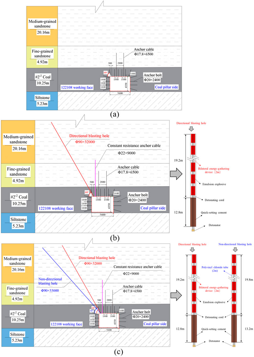
Roof cutting parameters for each section were determined through a combination of field conditions, theoretical analysis, and numerical simulations: Section A (uncut roof) maintained standard support configurations (Figure 16a); Section B (directional roof cutting) employed 32 m deep, 90 mm diameter blast holes drilled at 60° to horizontal, with 19.2 m explosive charge and 12.8 m grouted seal (Figure 16b); and Section C (compound roof cutting) retained identical directional hole parameters while adding non-directional blast holes (33 m deep, 90 mm diameter, 50° inclination, 19.8 m charge length, 13.2 m grouted seal, Figure 16c). All holes utilized detonating cord initiation and were sealed with accelerated cement grout.
6.1.3 Monitoring scheme
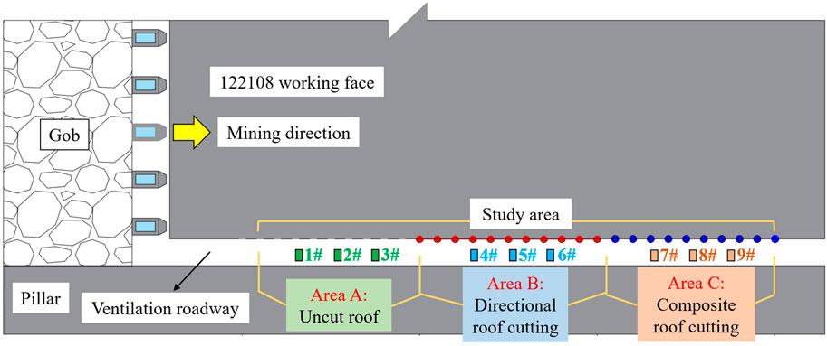
Nine monitoring stations were established across the experimental zone according to site-specific conditions: Stations 1–3 in Section A (uncut roof), Stations 4–6 in Section B (directional roof cutting), and Stations 7–9 in Section C (compound roof cutting). This configuration was dedicated to measuring surrounding rock deformation in each section, with their spatial distribution depicted in Figure 17.
6.2 Effect assessment
Deformation monitoring of the roadway surrounding rock functioned as a critical indicator for evaluating pressure relief effectiveness. Figure 18 presents the deformation monitoring curves for the roof-to-floor convergence and sidewall convergence within three study areas of the test working face roadway. Monitoring data from Stations 3#, 6#, and 9#, corresponding respectively to the non-roof cutting test section (Area A), the directional roof cutting test section (Area B), and the compound roof cutting test section (Area C), were hereby selected for comparative analysis. As illustrated in Figure 18, the monitoring data illustrated the deformation response as the working face advanced towards each station from a position 75 m ahead. Compared to the non-roof cutting area, both the directional and compound roof cutting areas exhibited a significant reduction in both the deformation rate and the final stabilized value of the roadway. As the working face progressively approached the stations, the final roof-to-floor convergence in the non-roof cutting area reached 732 mm. In contrast, this value decreased to 436 mm (a reduction of 40.4%) in the directional roof cutting area and further to 287 mm (a reduction of 60.8%) in the compound roof cutting area. Consistently, the final sidewall convergence was 448 mm in the non-roof cutting area, whereas it decreased to 260 mm (a reduction of 42.0%) and 151 mm (a reduction of 66.3%) in the directional and compound roof cutting areas, respectively. The monitoring data of the roadway surrounding rock showed that both directional and compound roof cutting methods could remarkably reduce roadway deformation. Notably, the compound roof cutting pressure relief method was more effective compared to the directional one, minimizing the workload and cost of roadway maintenance to the greatest extent. This approach thus achieved the goals of roadway protection and safe coal mining.
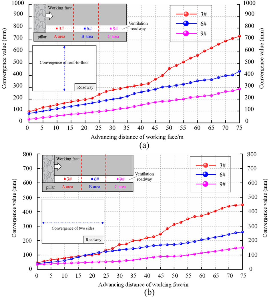
Figure 18. Monitoring of deformation of surrounding rock in roadways: (a) Convergence of roof and floor; (b) Convergence of two sides.
7 Conclusion
(1) To effectively address the deformation and failure of surrounding rock in high-stress roadways beneath thick sandstone roofs, numerical simulation methods were hereby employed to develop a crushed stone backfill model. This model was utilized to conduct an in-depth investigation into the bulking characteristics of gangue and the size effect on its bearing capacity. The results demonstrated that within a specific size range, smaller gangue particle sizes and more irregular accumulation morphologies correlated with higher porosity, yielding a larger fragmentation expansion coefficient and enhanced bearing performance. Leveraging this critical bulking characteristic of gangue, this study proposed an innovative composite roof cutting pressure-relief technology that integrated directional and non-directional roof cutting.
(2) To elucidate the control mechanism of the novel method, theoretical models of the roof structure were developed for three distinct conditions: non-roof cutting, directional roof cutting, and composite roof cutting. Comparative analysis revealed that the composite roof cutting technology substantially enhanced the supporting efficacy of gangue in the goaf, effectively reduced the mine pressure borne by the solid coal section, and promoted the attainment of a self-balancing state in the near-field surrounding rock. Subsequently, supporting numerical simulation studies were conducted to further validate the control effectiveness of this technology. Simulation results confirmed that the proposed composite roof cutting method fully exploited the bulking characteristics of gangue, effectively suppressed the movement of overlying strata, and significantly reduced the stress in the surrounding rock on the solid coal side of the roadway.
(3) Following theoretical analysis and numerical simulations, this study implemented the composite roof cutting pressure relief technology in field engineering trials. Three comparative sections were established: a non-roof cutting section, a directional roof cutting section, and a composite roof cutting section. Surrounding rock deformation in each test section underwent systematic monitoring and analysis. Field measurement data revealed that both directional roof cutting and composite roof cutting methods effectively suppressed roadway surrounding rock deformation, with the composite technique exhibiting notably better performance than the single directional approach. This approach optimally reduced roadway maintenance workload and costs, robustly validating the engineering feasibility and effectiveness of the composite roof cutting pressure relief technology. The application of this novel technology successfully ensured roadway stability and safe coal mining. Notably, this technology was hereby confirmed to hold substantial potential for broad application in addressing mining challenges under conditions of thick, hard roof strata and intense mine pressure conditions.
Data availability statement
The original contributions presented in the study are included in the article/supplementary material, further inquiries can be directed to the corresponding authors.
Author contributions
HG: Conceptualization, Formal Analysis, Funding acquisition, Methodology, Project administration, Resources, Supervision, Validation, Writing – original draft, Writing – review and editing. SZ: Conceptualization, Funding acquisition, Methodology, Supervision, Writing – review and editing. YS: Validation, Writing – review and editing. YL: Conceptualization, Formal Analysis, Funding acquisition, Project administration, Supervision, Writing – review and editing. KL: Methodology, Validation, Writing – review and editing. QF: Conceptualization, Methodology, Resources, Writing – review and editing. GH: Resources, Writing – review and editing. WR: Formal Analysis, Writing – review and editing. ZZ: Formal Analysis, Writing – review and editing. LC: Resources, Writing – review and editing. HL: Formal Analysis, Writing – review and editing.
Funding
The author(s) declare that financial support was received for the research and/or publication of this article. This work is supported by National Natural Science Foundation of China (No. 52474230), the Project supported by the National Key Research and Development Program of China (No.2024YFC2909504), the Science and Technology Development Fund Project of China Coal Research Institute (No.2024QN-06), the Project supported by the Young Scientists Fund of the National Natural Science Foundation of China (No.52404215) and Science and Technology In-novation Fund of TianDi Science and Technology Co., Ltd. (NO.2024-TD-ZD010-01), which are gratefully acknowledged. The authors declare that this study received funding from TianDi Science and Technology Co., Ltd. The funder was not involved in the study design, collection, analysis, interpretation of data, the writing of this article, or the decision to submit it for publication.
Conflict of interest
Author GH was employed by Jinneng Holding Equipment Manufacturing Group Co., Ltd. Author LC was employed by China Coal Datong Energy Co., Ltd.
The remaining authors declare that the research was conducted in the absence of any commercial or financial relationships that could be construed as a potential conflict of interest.
The reviewer HD declared a shared affiliation with the author QF to the handling editor at time of review.
Generative AI statement
The author(s) declare that no Generative AI was used in the creation of this manuscript.
Publisher’s note
All claims expressed in this article are solely those of the authors and do not necessarily represent those of their affiliated organizations, or those of the publisher, the editors and the reviewers. Any product that may be evaluated in this article, or claim that may be made by its manufacturer, is not guaranteed or endorsed by the publisher.
References
Bai, X. F., Ding, H., Lian, J. J., Ma, D., Yang, X. Y., Sun, N. X., et al. (2018). Coal production in China: past, present, and future projections. Int. Geol. Rev. 60 (5-6), 535–547. doi:10.1080/00206814.2017.1301226
Chen, Y., Zhang, Z. K., Cao, C., Bao, S. J., Wang, S., and Xu, G. Y. (2023). Research on the causal mechanism of a rock burst accident in a longwall roadway and its prevention measures. Sci. Rep-Uk 13 (1), 22312. doi:10.1038/s41598-023-41769-z
Dang, J. X., Tu, M., Zhang, X. Y., and Bu, Q. W. (2024). Research on the bearing characteristics of brackets in thick hard roof mining sites and the effect of blasting on roof control. Geomech. Geophys Geo 10 (1), 18. doi:10.1007/s40948-024-00735-3
Fu, Q., Yang, J., Song, H. X., Wu, X., Liu, Y. X., and Wei, X. J. (2023). Study on the method of pressure relief and energy absorption for protecting roadway under thick and hard roof. Rock Mech. Rock Eng. 56 (10), 7177–7196. doi:10.1007/s00603-023-03447-4
Hao, Y. X., Li, M. L., Wang, W., Zhang, Z. Z., and Li, Z. (2023). Study on the stress distribution and stability control of surrounding rock of reserved roadway with hard roof. Sustainability-Basel 15 (19), 14111. doi:10.3390/su151914111
Hu, C. W., Yang, X. J., Huang, R. F., and Ma, X. G. (2020). Presplitting blasting the roof strata to control large deformation in the deep mine roadway. Adv. Civ. Eng. 2020, 8886991. doi:10.1155/2020/8886991
Li, Z. H., Zhang, J. H., Chen, H., Shi, X. Z., Zhang, Y. Y., and Zhang, Y. J. (2022). A safe and efficient mining method with reasonable stress release and surface ecological protection. Sustainability-Basel 14 (9), 5348. doi:10.3390/su14095348
Li, J. K., Zhang, J., Gong, L. T., and Miao, P. (2015). The spatial and temporal distribution of coal resource and its utilization in china - based on space exploration analysis technique esda. Energ Environ-Uk 26 (6-7), 1099–1113. doi:10.1260/0958-305X.26.6-7.1099
Li, S. C., Wang, Q., Wang, H. T., Jiang, B., Wang, D. C., Zhang, B., et al. (2015). Model test study on surrounding rock deformation and failure mechanisms of deep roadways with thick top coal. Tunn. Undergr. Sp. Tech. 47, 52–63. doi:10.1016/j.tust.2014.12.013
Lin, B. Q., and Liu, J. H. (2010). Estimating coal production peak and trends of coal imports in China. Energ. Policy. 38 (1), 512–519. doi:10.1016/j.enpol.2009.09.042
Liu, X. Y., He, M. C., Wang, J., and Ma, Z. M. (2021). Research on non-pillar coal mining for thick and hard conglomerate roof. Energies 14 (2), 299. doi:10.3390/en14020299
Lu, X. L., Liu, Q. S., and Su, P. F. (2013). Failure mechanism recognition and optimum support design of roadway groups in soft and fractured surrounding rock - case study: paner coal mine. Disaster Adv. 6, 406–414. Available online at: https://www.mendeley.com/catalogue/6f9fedba-3a75-3953-983b-8b88036d5324.
Meng, N. K., Bai, J. B., and Yoo, C. (2023). Failure mechanism and control technology of deep soft-rock roadways: numerical simulation and field study. Undergr. Space 12, 1–17. doi:10.1016/j.undsp.2023.02.002
Pan, C., Xia, B. W., Zuo, Y. J., Yu, B., and Ou, C. N. (2022). Mechanism and control technology of strong ground pressure behaviour induced by high-position hard roofs in extra-thick coal seam mining. Int. J. Min. Sci. Techno. 32 (3), 499–511. doi:10.1016/j.ijmst.2022.01.006
Qin, D. D., Wang, X. F., Zhang, D. S., Guan, W. M., Zhang, L., and Xu, M. T. (2019). Occurrence characteristic and mining technology of ultra-thick coal seam in Xinjiang, China. Sustainability-Basel 11 (22), 6470. doi:10.3390/su11226470
Wang, B., Feng, G. R., Gao, Z. X., Ma, J. P., Zhu, S. T., Bai, J. W., et al. (2023). Study on the mechanism and prevention of frequent mine seismic events in goaf mining under a multi-layer thick hard roof: a case study. Minerals-Basel 13 (7), 852. doi:10.3390/min13070852
Wang, J. L., Feng, L. Y., Davidsson, S., and Höök, M. (2013a). Chinese coal supply and future production outlooks. Energy 60, 204–214. doi:10.1016/j.energy.2013.07.031
Wang, J. L., Feng, L. Y., and Tverberg, G. E. (2013b). An analysis of China's coal supply and its impact on China's future economic growth. Energ. Policy. 57, 542–551. doi:10.1016/j.enpol.2013.02.034
Wang, E., Yin, S. F., Kang, Q. T., Zhao, X. B., Lan, Q. K., Sheng, H. Y., et al. (2024). Coupling control technology of anchoring and unloading in deep intense-mining and large-deformation roadway: a case study. Sci. Rep-Uk 14 (1), 12075. doi:10.1038/s41598-024-61029-y
Wang, Q., Jiang, Z. H., Jiang, B., He, M. C., Yang, J., and Xue, H. J. (2023). Ground control method of using roof cutting pressure release and energy-absorbing reinforcement for roadway with extra-thick hard roof. Rock Mech. Rock Eng. 56 (10), 7197–7215. doi:10.1007/s00603-023-03461-6
Xiang, Z., Zhang, N., Xie, Z. Z., Guo, F., and Zhang, C. H. (2021). Cooperative control mechanism of long flexible bolts and blasting pressure relief in hard roof roadways of extra-thick coal seams: a case study. Appl. Sci-Basel. 11 (9), 4125. doi:10.3390/app11094125
Xu, Z. Y., Liu, A. B., Ren, F. Q., Yan, Y. R., Zhang, Z. F., and Wang, X. S. (2025). Collapse characteristics and mechanisms of shallow cross roadways under mining blasting disturbance. J. Mt. Sci. 22 (3), 1101–1118. doi:10.1007/s11629-024-9285-5
Yan, H., Zhang, J. X., Feng, R. M., Wang, W., Lan, Y. W., and Xu, Z. J. (2020). Surrounding rock failure analysis of retreating roadways and the control technique for extra-thick coal seams under fully-mechanized top caving and intensive mining conditions: a case study. Tunn. Undergr. Sp. Tech. 97, 103241. doi:10.1016/j.tust.2019.103241
Yang, X. J., Wang, E. Y., Wang, Y. J., Gao, Y. B., and Wang, P. (2018). A study of the large deformation mechanism and control techniques for deep soft rock roadways. Sustainability-Basel 10 (4), 1100. doi:10.3390/su10041100
Zhang, X. Y., Pak, R., Gao, Y. B., Liu, C. K., Zhang, C., Yang, J., et al. (2020). Field experiment on directional roof presplitting for pressure relief of retained roadways. Int. J. Rock Mech. Min. 134, 104436. doi:10.1016/j.ijrmms.2020.104436
Zhang, X. T., Ning, Y. C., and Lu, C. J. (2022). Evaluation of coal supply and demand security in China and associated obstacle factors. Sustainability-Basel 14 (17), 10605. doi:10.3390/su141710605
Zhang, X. T., Wang, F. T., Qu, H. F., Liu, C., Li, Z., and Hao, W. H. (2023). Surrounding rocks deformation mechanism and roof cut-ting-grouting joint control technology for soft and thick coal seam roadway. Sustainability-Basel 15 (21), 15415. doi:10.3390/su152115415
Zhang, B. C., Zhang, S. C., Shen, B. T., Li, Y. Y., Song, S. L., Han, X. X., et al. (2024). Simulation and on-site monitoring of de-formation characteristics of roadway excavation along goaf in soft and thick coal seams in Western mining areas. Appl. Sci-Basel 14 (17), 7760. doi:10.3390/app14177760
Zhang, X. G., Xia, B. W., Xia, N., Zhou, L., and Gong, T. (2025). Material point method for simulating strong mining pressure manifes-tation in multiple hard roof panels controlled by hydraulic fracturing. Front. Earth Sci. 13, 1528088. doi:10.3389/feart.2025.1528088
Zhao, H. B., Zhang, B., Gao, L., Jing, S. J., and Cheng, H. (2025). Static blasting roof cutting surrounding rock control technology for narrow coal pillar gob-side entry driving in thick coal seams. Int. J. Geomech. 25 (6), 04025083. doi:10.1061/IJGNAI.GMENG-10861
Zhou, J. L., Pan, J. F., Xia, Y. X., Du, T. T., Liu, W. A., and Zhang, C. Y. (2024). Mechanism and prevention of coal bursts in gob-side roadway floor under thick and hard roof in the deep mining area of Ordos. Int. J. Coal Sci. Techn. 11 (1), 80. doi:10.1007/s40789-024-00734-5
Keywords: thick sandstone roof, surrounding rock control, gangue fragmentation and expansion, roof cutting and pressure relief, field application
Citation: Gao H, Zhao S, Shi Y, Li Y, Lv K, Fu Q, He G, Ren W, Zhou Z, Chen L and Li H (2025) Research on mechanism and application of compound roof cutting and pressure relief control in thick sandstone roof mining roadways. Front. Earth Sci. 13:1655663. doi: 10.3389/feart.2025.1655663
Received: 02 July 2025; Accepted: 30 July 2025;
Published: 14 August 2025.
Edited by:
Manoj Khandelwal, Federation University Australia, AustraliaReviewed by:
Han Du, Tsinghua University, ChinaAvinash Paul, Central Institute of Mining and Fuel Research, India
Peng Liu, China University of Mining and Technology, China
Shitan Gu, Shandong University of Science and Technology, China
Copyright © 2025 Gao, Zhao, Shi, Li, Lv, Fu, He, Ren, Zhou, Chen and Li. This is an open-access article distributed under the terms of the Creative Commons Attribution License (CC BY). The use, distribution or reproduction in other forums is permitted, provided the original author(s) and the copyright owner(s) are credited and that the original publication in this journal is cited, in accordance with accepted academic practice. No use, distribution or reproduction is permitted which does not comply with these terms.
*Correspondence: Shankun Zhao, emhhb3NoYW5rdW5jb21AMTYzLmNvbQ==; Qiang Fu, Y3VtdGJmcUAxNjMuY29t; Yue Shi, c2hpeXVlX2N1bXRiQDEyNi5jb20=
 Hainan Gao
 Shankun Zhao1*
 Qiang Fu