 Ye Jun-Neng
 Wang Zhong-Jin2*
- 1Ningbo Rail Transit Group Co., Ltd., Ningbo, China
- 2School of civil engineering, NingboTech University, Ningbo, China
- 3Ningbo Ningda Foundation Treatment Technology Co., Ltd., Ningbo, China
- 4Zhejiang Hongchen Construction Co., Ltd., Ningbo, Zhejiang, China
As a new type of composite pile, the synchronously and concentrically constructed steel pipe–cemented soil composite pile has been increasingly adopted as an inclined support system in foundation pit engineering. However, theoretical research on the mechanical behavior and calculation methods of this composite pile has lagged behind its practical engineering applications. In this study, a series of laboratory tests were conducted to investigate the interaction between the steel pipe and the surrounding cemented soil. A novel calculation method is proposed for the bearing capacity and deformation behavior of the new composite inclined pile. In this new model, the steel pipe and the inner cemented soil are assumed to have no relative displacement and are treated as a single pile body using an equivalent modulus approach. The surrounding cemented soil primarily undergoes shear deformation, and its interaction with the natural soil is also modeled as ideal elastoplastic. The end resistance–displacement behavior of the cemented soil is described using a hyperbolic relationship. The influence of key parameters on the pile performance was also analyzed. Practical methods for determining the main parameters were provided. The results show that the proposed calculation method agrees well with the engineering measurements, demonstrating its applicability for evaluating the bearing characteristics of this new composite pile type and offering valuable guidance for practical engineering design and implementation.
1 Introduction
As a temporary structure in engineering construction, the stability and safety of the foundation pit enclosure system are important to the successful completion of the entire project. As traditional pit support methods, reinforced concrete internal bracing systems and row pile-anchor cable systems have gradually been proven with significant limitations. The above traditional methods required lengthy construction periods, also had many difficulties in dismantling and adverse impacts on the surrounding environment. Consequently, the development of efficient, easily removable, and environmentally friendly pit support technologies has become a pressing challenge in the field of geotechnical engineering.
In recent years, composite piles have been extensively studied world widely. These piles typically consist of high-strength core pile and cemented soil. Its construction commonly involves the formation of cement-soil piles via deep mixing or jet grouting, following by the insertion of typical prefabricated tubular core piles or steel pipe core piles (Fleming, 1993; Wang et al., 1998; Guo et al., 2006; Yu et al., 2020). The composite pile fully utilizes the high axial bearing capacity of the core pile while making full use of the large shaft resistance provided by the surrounding cemented soil, which has a large surface area (Dong et al., 2002; Dong et al., 2004). By combining the advantages of both types of piles, the bearing capacity is significantly enhanced and overall settlement is effectively reduced. Experimental tests and finite element analyses have shown that the load-settlement behavior of strong hydraulic composite piles exhibits slow-changing nonlinearity (Li et al., 2009; Li et al., 2014; Zhang et al., 2015; Rui et al., 2018). In this system, the high-strength core pile and the surrounding cemented soil primarily bear the axial load, while the contribution of the end-bearing is relatively minor. Numerical simulations have been conducted to investigate the influence of core pile and the core-to-total pile length ratio on the vertical bearing capacity of strong composite piles (Voottipruex et al., 2011; Wang et al., 2013). The results indicate that increasing the core length ratio leads to a significant improvement in vertical bearing capacity. However, increasing the core content only results in a limited increase in bearing capacity. Similar conclusions have been drawn from both laboratory model tests and numerical simulations (Wonglert and Jongpradist, 2015; Zhou et al., 2022). As for the load transfer mechanism of the above mentioned composite piles, a load-settlement analytical solution for concrete core piles in homogeneous soil layers was developed based on the load transfer method, and a corresponding approach was proposed to predict the settlement behavior of composite piles in layered soils (Wu, 2008; Liu et al., 2010; Zhao et al., 2010). Based on the load transfer method, a simplified method was introduced for jet grouting cemented soil piles under various configurations. The above method can consider both the frictional interaction between the cemented-soil and the core pile, as well as between the cemented-soil and the surrounding soils (Ren et al., 2010). Furthermore, a load transfer model for strong mixed piles was established based on the principles of composite mechanics and elastic displacement solution. This model derived expressions for the axial stress of the core pile and the shear stress distribution at the interface between the core pile and the cemented soil, using equilibrium equations for a differential element and the shear-lag theory (Gu et al., 2011; Zhang and Ma, 2022). In addition, a model for strong composite piles with rigid end bearing was developed to analyze the load transfer behavior in layered soils. The model identified the interface interaction between the inner and outer piles during the loading process, with three stages of elastic, softening, and shear slip respectively (Jamsawang et al., 2008; Zhu et al., 2022).
Based on the theoretical load transfer analyze, the load transfer behavior of equal-core strong composite piles under flexible foundation conditions has been systematically investigated (Chen et al., 2023; Jiu et al., 2024). Through theoretical analysis and iterative algorithms, a calculation model was developed to express the nonlinear interaction between pile and soil, providing theoretical support for understanding the bearing behavior of this type pile. A simplified calculation model for strong mixing piles was also proposed under the assumption that no slip occurs at the interface between the core pile and the surrounding cemented soil (Wang et al., 2018; Du et al., 2018). Another simplified model was established for core piles, which considered the shear behavior at the interface between the inner and outer piles (Tang et al., 2020; Zhang et al., 2024). In addition, a series of laboratory tests were conducted on cemented soils with different curing durations to investigate the effects of curing time, mix proportion, and confining pressure on the compressive and shear strength of the cemented soil. To further explore the mechanical performance of cemented soil wrapped piles used for foundation pit support, horizontal displacement monitoring tests were carried out. The results indicated that increasing the strength of the cemented soil significantly improves the deformation resistance of the support structure (Bao et al., 2023; Zhang et al., 2024).
Inclined pile support is a relatively novel foundation system that eliminates the need for internal reinforced concrete bracing. In recent years, it has been increasingly adopted in soft soil areas. The piles used in such systems are generally categorized into prefabricated piles and strong steel pipe piles. As an innovative form of pit support, the composite inclined pile consists of a steel pipe and high-pressure grouted cemented soil piles. This new type of pile integrates a high-strength steel pipe with a high-pressure jet grouted cement-soil column through a concentric and synchronous construction process. Due to its structural advantages and adaptability to soft soil conditions, this technique has attracted increasing attention in geotechnical engineering, as illustrated in Figure 1.
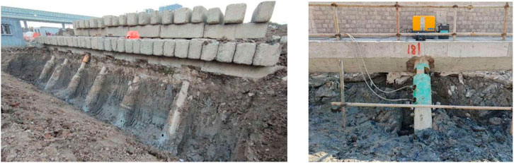
Figure 1. Actual engineering application case.
This support structure effectively controls the deformation of the foundation pit, provides a spacious working environment for excavation and underground construction, which significantly improves construction efficiency. It also reduces project costs and minimizes adverse impacts on the surrounding environment. Although the composite inclined pile has been successfully applied in many foundation pit projects (Hu and Pu, 2001; Zhu et al., 2020), the theoretical research on its mechanical behavior and calculation methods remains unsystematic and insufficient. The study of this new type composite piles composed of steel pipe and cemented soil has considerable theoretical and practical significance for their wider application in large-scale foundation pit projects. Based on laboratory experimental research and actual construction and excavation data, this study proposes a simplified analytical method for the inclined composite pile under reasonable assumptions. Additionally, the influence of key parameters on the bearing capacity and deformation behavior of the composite inclined pile was investigated, and the analytical results were compared with actual project measurements. The comparison demonstrates that the proposed method is applicable and reliable for the design and analysis of foundation pits utilizing this new pile type.
2 Experimental research and assumptions for the computational methods
2.1 The relationship between steel pipe and surrounding cemented soils
In order to explore the contact characteristics between the steel pipe pile and surrounding cemented soils, a batch of samples were made, which use for interface contact strength tests. The detailed parameters of the laboratory tests were shown in Table 1.
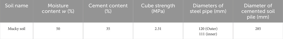
Table 1. The parameters of the laboratory tests with 7 days curing.
The interface frictional resistance between the steel pipe and outer cemented soil was studied through axial loading tests, as shown in Figure 2.
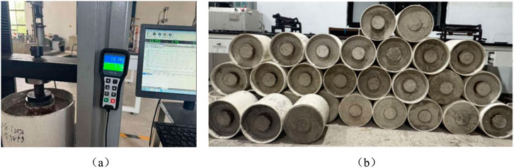
Figure 2. Interface contact test between the steel pipe and cemented soil pile. (a) Axial loading test (b) Samples made in the laboratory.
After 7 days of sample curing, axial loading tests were conducted to analyze the contact mechanical behavior between the steel pipe and the surrounding cemented soil. As shown in Figure 3, the experimental results show that as the relative displacement between the steel pipe and the surrounding cemented soil increases, the interface contact resistance also increases, eventually reaching a peak value. Upon completion of the initial loading test, the sample was left to stand for 10 min before repeating the loading process. The results indicated that the peak contact resistance in the repeated loading was approximately 80% of the maximum value obtained during the initial test. One day later, the axial loading test was repeated The results were generally consistent with those of the first loading test. When the test was repeated after another 10-min resting period, the maximum contact resistance was again found to be approximately 80% of the initial peak value.
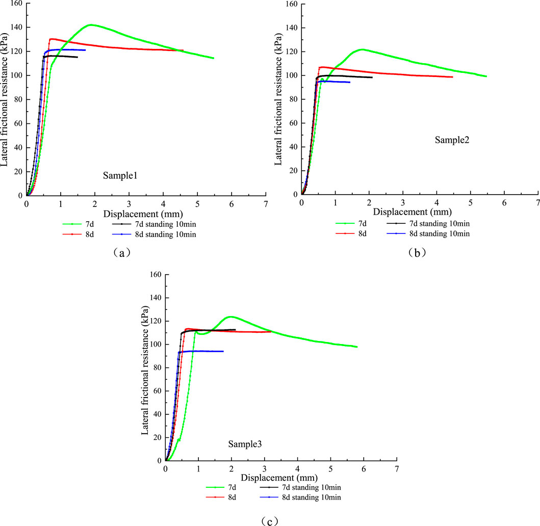
Figure 3. Results of interface contact loading tests. The (a–c) represent three different test samples.
In addition, this study analyzes the results from the on-site excavation of composite piles composed of steel pipe and cemented soil, as shown in Figure 4. Based on these field results, combined with previous experimental findings on pile–soil interaction (Lee and Xiao, 2001; Wang and Liu, 2008; Yu et al., 2022), it is assumed that the steel pipe and the inner core of cemented soil act as a unified member with no relative slip. Their mechanical behavior is modeled using an equivalent elastic modulus based on equal cross-section transformation. The load transfer method is used to describe the interaction between the steel pipe pile and the outer cemented soil. To compute the deformation of the cemented soil surrounding the steel pipe, the shear displacement method is adopted. The interaction between the outer cemented soil pile and the surrounding natural soil is modeled as an ideal elastic–plastic system. Based on these assumptions, a mechanical calculation model is developed to characterize the interaction between the steel pipe and the surrounding cemented soil.
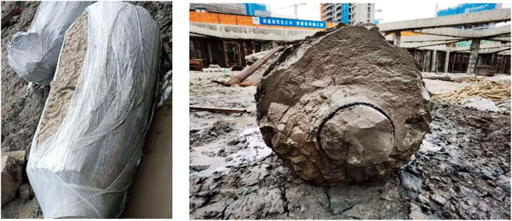
Figure 4. On site excavation test after load test.
The relationship between frictional resistance and relative displacement has been extensively studied by previous studies, and various load transfer models have been widely applied (Lee, 1993; Zhang et al., 2010; Wang et al., 2012). In this study, a series of systematic tests were carried out to investigate the interface behavior between the steel pipe and cemented soil with different curing ages. The results revealed that the frictional resistance–displacement relationship exhibits a linear trend in the initial loading stage, as shown in Figure 5a. Additionally, the load–settlement behavior at the cemented soil near the pile end follows a bilinear pattern, as illustrated in Figure 5b.
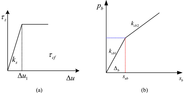
Figure 5. Calculation model of interaction between steel pipe and surrounding cement soils. (a) Interaction between steel pipe and surrounding cemented soil (b) Calculation model of steel pipe end and cement soils.
The expression for the relationships between the frictional resistance and the relative displacement can be written as the following Equation 1:
Where,
The relationship between steel pile end resistance and displacement at the cemented soil is simplified to the following Equation 2:
Where,
As shown in Figure 6, assuming that the coordinates at the end of the steel pipe is
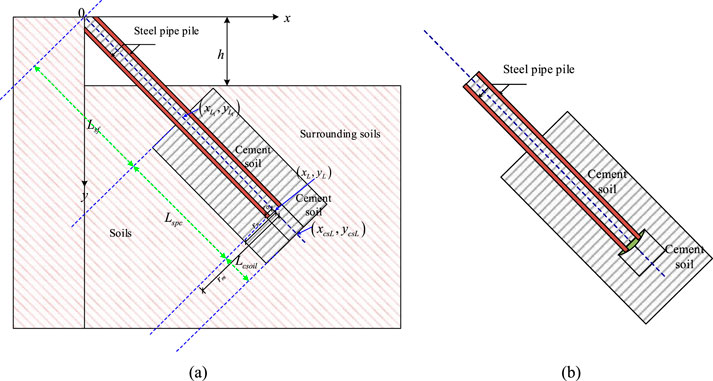
Figure 6. Simplified calculation diagram for steel pipe and cemented soil composite pile. (a) The calculation diagram (b) Relationship of steel pipe end and cement soil.
The outer radius of the steel pipe pile is
Assuming a slight displacement
The frictional resistance between the steel pipe and cemented soil at the corresponding position can be expressed by the following Equation 5 :
The total frictional resistance of the steel pipe from the steel pile end to the pile body z can be expressed as the following Equation 6:
The axial force of the steel pile body
The following differential equation can be obtained by second-order derivation, Equation 8.
The general solution of the second-order ordinary differential equation mentioned above can be expressed by the following Equation 9:
Where
The values of parameters C1 and C2 are obtained respectively by the following Equation 12:
The expressions for the axial force and displacement can be obtained:
Let
When the relative displacement between the steel pipe and the surrounding cemented soil is greater than
The friction and displacement and at section z can be calculated by the following Equation 19.
Existing studies and experimental test results have shown the ultimate relative displacement between the steel pipe pile and cemented soil is around 0.5 mm, as shown in Figure 4.
2.2 Calculations for cemented soil deformation surrounding steel pipe
For the cemented soil surrounding the steel pipe, assuming that it mainly undergoes shear deformation under the shaft resistance of the steel pile, this new composite type pile is constructed in a concentric synchronous manner, and the shear stress is transmitted from the outer cemented soil to the surrounding soil. Here, it is assumed that there is no relative displacement between the cemented soil and its surrounding soil, this assumption originates from the shear displacement method proposed by Poulos (1988) and Randolph and Guo (1999). Under the shaft frictional resistance of the steel pile, the shear strain of the cemented soil at a distance r from the pile axis is:
The shear stress is
By the equilibrium conditions, it can be obtained that:
Substituting Equation 22 into Equation 21, and the following expression can be obtained:
Substituting Equation 23 into Equation 20, and the following Equation 24 can be obtained:
2.3 Calculations of cemented soil pile and surrounding soil
Assuming that the shaft resistance at the outer cemented soil and the surrounding soils performs to an ideal elastoplastic relationship, as shown in Figure 7a. The load and displacement relationship developed at the cemented soil pile base and the soils follows the hyperbolic relationship, as shown in Figure 7b.
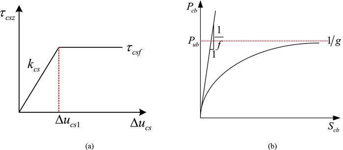
Figure 7. The Calculation model for cement pile and soil. (a) Model of cement soil pile and soils (b) Hyperbolic model of pile end load and settlement.
The shaft shear resistance between the outer cemented soil and surrounding soil can be expressed by the following Equation 25:
Among them, the resistance between the cemented soil pile and the surrounding soils at depth z is
Based on the research results by [43], the relationship between the end resistance and settlement of the soil below the cemented soil pile end along the z-axis is simplified as a hyperbolic model, as shown in Figure 7b, and can be written as the following Equation 26:
In the above formula,
Where
The values of
The expressions for the axial force and displacement of the cemented soil pile can be obtained separately by the Equations 31, 32:
When the relative displacement between the cemented soil pile and the surrounding soil is greater than
The compression deformation of the cemented soil pile above this position can be simplified as the following Equation 34:
In order to obtain the settlement at the end of the cemented soil pile accurately, the following calculation steps can be taken:
1. The total number of calculations is m, assuming a small displacement
2. The change of soil stiffness at the cemented soil pile end caused by the settlement at the pile end can be obtained from Equation 26. The expressions for each parameter in Equation 35 are:
3. For the (n-1)th calculation, the cemented soil pile top load and displacement for the (n-1)th calculation can be obtained by the following Equations 36, 37:
4. The changes in the relative displacement between the cemented pile and surrounding soils and the stiffness of the soil at the pile side are obtained from steps (2) and (3), and used in the next calculation process. The axial force and settlement of the cemented soil pile body obtained from each calculation are accumulated to obtain the total axial force and corresponding displacement distribution of the pile at different load levels.
According to the on-site excavation test results, there is no sliding failure between the steel pipe pile and the outer cemented soil. Therefore, the deformation of the steel pipe pile along the z-axis direction at any cross-section is expressed by the Equation 38:
3 Analysis of the values and influencing factors of relevant parameters
3.1 Determination of the values of parameters in the calculation method
As illustrated in Figure 4, experimental tests on the shaft stiffness between the steel pipe and the surrounding cemented soil piles have shown that the interface friction increases with curing age. Extensive test results on the shaft friction behavior between cemented soil and steel piles with varying diameters and curing durations further confirm this conclusion. According to the experimental results reported by Yu et al. (2022), the displacement parameter
According to the on-site excavation test results as shown in Figure 2, the new type of composite pile constructed synchronously and concentrically exhibits no relative displacement between the steel pipe and the internal cemented soil, even under ultimate loading conditions. Relative displacement is observed only in the upper portion of the pile, between the outer cemented soil and the steel pipe. In contrast, in the lower section of the composite pile, the outer cemented soil and the steel pipe remain well bonded. The stiffness of the cemented soil at the tip of the steel pipe pile is consistently maintained at a value of
In this new type of composite inclined pile, a high-pressure grouted cemented soil segment approximately 1 m in length is formed below the tip of the steel pipe pile along the axial direction. The end resistance of the steel pipe pile is closely related to the deformation behavior of this cemented soil segment, and their relationship is nonlinear and relatively complex. To investigate this interaction, finite element analysis was employed to simulate the relationship between the pile end resistance and the deformation of the cemented soil. The simulation results indicate that when the cemented soil deformation is within 10 mm, the pile end resistance increases approximately linearly with the deformation. Beyond this point, the rate of increase slows down due to the onset of plastic deformation in the cemented soil, as illustrated in Figure 8. Field excavation and measurement results further confirm that, under working load conditions, the relative displacement between the steel pipe pile end and the surrounding cemented soil remains within the linear response range. The value of
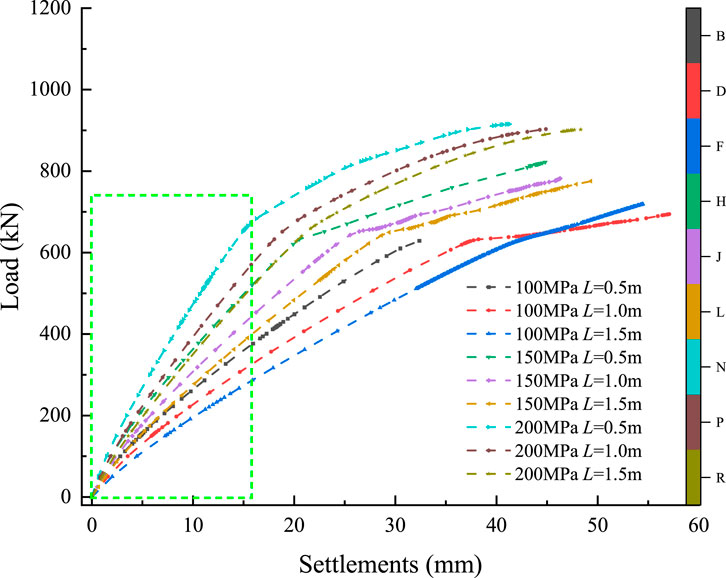
Figure 8. Resistance between cement soil displacement and steel pipe end.
The deformation stiffness of the soil at the end of the cemented soil pile can be calculated using the following formula suggested by Randolph and Wroth (1978) in the Equation 39:
The parameter f is the reciprocal of the initial stiffness
The parameters
Where,
Where,
3.2 Calculation method of composite pile stress in layered soil foundation
In practical engineering, pile foundation construction sites are usually on uneven strata as shown in Figure 9. In layered soil sites, the average stiffness of the shaft resistance for the steel pipe and cemented soil composite pile foundations is calculated as the following Equation 43:
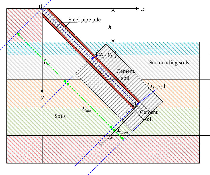
Figure 9. The calculation model for layered soils.
Because the construction of this new type of composite pile forms a certain angle
3.3 Analysis of bearing characteristics of the steel pipe pile
As shown in Figures 10, 11, both the axial force and the displacement of the steel pipe pile decrease progressively along the pile’s axial direction. Typically, the axial force and displacement are relatively large in the upper section of the composite pile and gradually diminish toward the lower section. As show in Figure 10, it can be observed that as the load applied at the pile top increases, the interaction between the steel pipe and the surrounding cemented soil in the upper portion of the pile becomes more significant. However, this interaction remains relatively weak in the lower section of the composite pile. Figure 11 further illustrates that the relative displacement between the steel pipe and the surrounding cemented soil increases with increasing load at the pile top. Along the axial direction, this relative displacement becomes more pronounced with higher applied loads, while remaining relatively small in the lower segment of the composite pile shaft. From the above analysis, it can be concluded that under axial loading, the interaction between the steel pipe and the surrounding cemented soil is primarily concentrated along the shaft of this new type of composite inclined pile. The end resistance interaction at the pile tip is relatively weak.
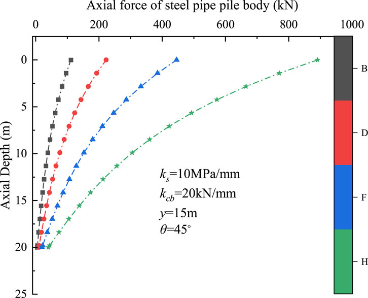
Figure 10. Example of axial force distribution of steel pipe pile body.
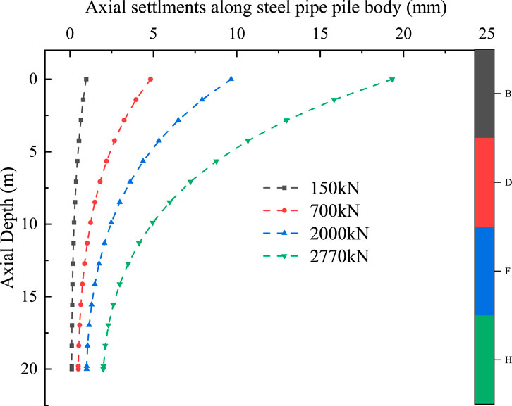
Figure 11. Example of displacement distribution of steel pipe pile body.
The relationship between load and settlement of the cemented soil is presented in Figure 12. It can be observed that the pile top load and corresponding settlement exhibit an approximately linear relationship within a certain loading range. As the applied load continues to increase, the rate of settlement also increases, indicating a nonlinear response at higher load levels. The numerical simulation results are consistent with the trend observed in the engineering field measurements.
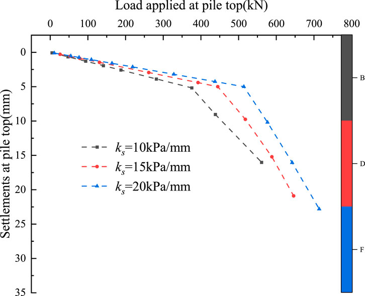
Figure 12. Example of load settlement relationship for cemented soil pile.
4 Comparative analysis of engineering applications
This project is located in Ningbo City and features a basement structure comprising one underground level and a two-level basement in different sections. For the first basement level, a combination of row piles, inclined piles, and horizontal concrete corner braces was used for support. The designed excavation depth ranges from 6.0 to 8.7 m. The supporting piles include SMW (Soil Mixing Wall) method piles and bored cast-in-place concrete piles. In this project, the newly developed inclined composite piles were adopted as part of the slant support system. The typical length of these inclined composite piles is approximately 32 m, and the standard value of their designed ultimate bearing capacity is 2200 kN. The detailed soil parameters of the site were shown in Table 2.
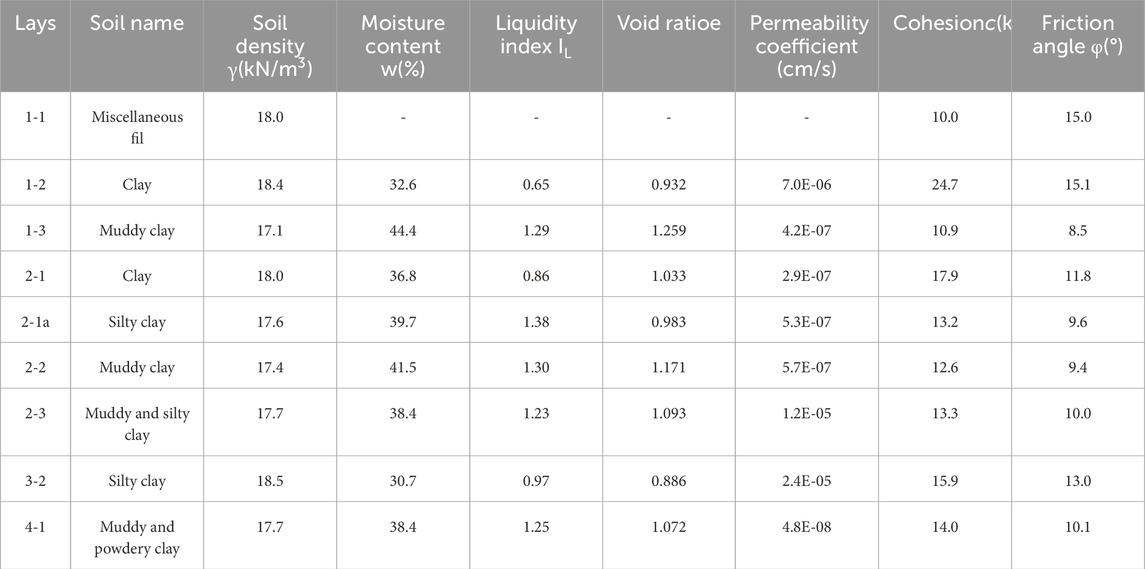
Table 2. Soil parameters of the site.
Comparisons between the load–settlement curves obtained using the proposed method and the measured results are presented in Figure 13. As shown in Figure 13, the load–settlement relationship at the pile head calculated by the proposed approach aligns well with the experimental data, demonstrating good overall agreement with the measured behavior. These calculated results are in good agreement with the excavation test data obtained from the construction site, as shown in Figure 13.
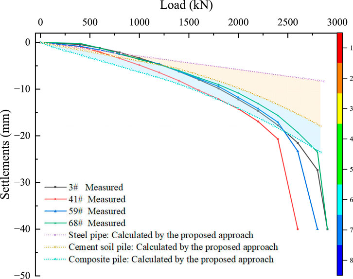
Figure 13. Comparison between the measured and computed results for a single pile in multilayered soils.
5 Conclusion
This paper presents a simplified analytical method to analyze the bearing characteristics of the new type inclined pile, which was composed of steel pipe pile and cemented soil constructed by synchronous and concentrically technique. The primary conclusion s are as follows:
1. The transfer functions to analyze the interactions between the steel pipe pile and the surrounding cemented soil, the interactions between the outer cemented soil pile and the surrounding natural soil are presented in this paper. The assumptions based on the excavation test results are reasonable applicable for the analysis of the new composite inclined pile.
2. The linear relationship can be used to simulate the contact behavior between the outer cemented soil pile and the surrounding soils, and the hyperbolic relationship can be used to describe the end resistance and displacement at the end of the cemented soil. The axial force and displacement of the steel pipe pile decrease substantially along the axial direction. The relative displacements between the steel pipe pile and surrounding cemented soils are mainly concentrated in the upper part of the composite pile section.
3. The total head (top) displacement of the new composite inclined pile consists of multiple components: axial compression of the steel pipe pile, shear deformation of the cemented soil along the pile shaft, relative displacement between the cemented soil and the surrounding soil, and end displacement of the cemented soil pile.
4. The proposed calculation method demonstrates good agreement with the results of engineering tests, validating its feasibility for analyzing and designing this new type of composite inclined pile.
Data availability statement
The original contributions presented in the study are included in the article/supplementary material, further inquiries can be directed to the corresponding author.
Author contributions
YJ-N: Writing – review and editing, Writing – original draft, Funding acquisition. WZJ: Writing – review and editing, Funding acquisition, Writing – original draft, Formal Analysis. ZK-C: Writing – review and editing, Data curation, Investigation. SS-Y: Writing – review and editing, Investigation, Methodology. MH-H: Project administration, Methodology, Writing – review and editing. WQ-H: Resources, Methodology, Writing – review and editing, Investigation.
Funding
The author(s) declare that financial support was received for the research and/or publication of this article. The work was supported by the Public Welfare Science and Technology Projects of Ningbo (Grant Number: 2024S079) and the National Natural Science Foundation of China (Grant No. 52478365).
Acknowledgments
These supports are gratefully acknowledged.
Conflict of interest
Author YJ-N was employed by Ningbo Rail Transit Group Co., Ltd.
Authors SS-Y and MH-H were employed by Ningbo Ningda Foundation Treatment Technology Co., Ltd.
Author WQ-H was employed by Zhejiang Hongchen Construction Co., Ltd.
The remaining authors declare that the research was conducted in the absence of any commercial or financial relationships that could be construed as a potential conflict of interest.
Generative AI statement
The author(s) declare that no Generative AI was used in the creation of this manuscript.
Any alternative text (alt text) provided alongside figures in this article has been generated by Frontiers with the support of artificial intelligence and reasonable efforts have been made to ensure accuracy, including review by the authors wherever possible. If you identify any issues, please contact us.
Publisher’s note
All claims expressed in this article are solely those of the authors and do not necessarily represent those of their affiliated organizations, or those of the publisher, the editors and the reviewers. Any product that may be evaluated in this article, or claim that may be made by its manufacturer, is not guaranteed or endorsed by the publisher.
References
Bao, X., Cheng, Z., Shen, J., Zhang, X., and Cui, H. (2023). Study on bearing capacity of reinforced composite pipe pile group in reclaimed stratum under vertical load. J. Mar. Sci. Eng. 11, 597. doi:10.3390/jmse11030597
Chen, C., Chen, S., Zhu, S., and Cai, H. (2023). Analysis on load transfer behaviors of equal-core stiffened deep mixed pile under flexible foundation. J. Hunan Univ. (Nat. Sci.) 50, 152–160. doi:10.16339/j.cnki.hdxbzkb.2023016
Coyle, H. M., and Reese, L. C. (1966). Load transfer for axially loaded piles in clay. J. Soil Mech. Found. Div. 92, 1–26. doi:10.1061/JSFEAQ.0000850
Dong, P., Chen, Z., and Qin, R. (2002). Use of concrete-cored DCM pile in soft ground. Chin. J. Geotech. Eng. 24, 204–207.
Dong, P., Qin, R., and Chen, Z. (2004). Bearing capacity and settlement of concrete-cored DCM pile in soft ground. Geotech. Geol. Eng. 22, 105–119. doi:10.1023/B:GEGE.0000013994.73567.cc
Du, G., Wang, A., Li, L., and Zhang, D. (2018). Calculation approach for lateral bearing capacity of single precast concrete piles with improved soil surrounds. Adv. Civ. Eng. 2018, 5127927. doi:10.1155/2018/5127927
Fleming, W. G. K. (1993). A new method for single pile settlement prediction and analysis. Géotechnique 43, 615–618. doi:10.1680/geot.1993.43.4.615
Gu, S., Shi, J., Wang, C., and Tan, Y. (2011). Theoretical study of core pile load transfer regularity of reinforced mixing pile. Rock Soil Mech. 32, 2473–2478. doi:10.16285/j.rsm.2011.08.050
Guo, Z. X., Yang, Z. H., and Wang, Z. L. (2006). Experimental study of load transfer behavior of rammed soil-cement piles. Rock Soil Mech. 27, 2020–2024. doi:10.16285/j.rsm.2006.11.032
Hu, L., and Pu, J. (2001). Experimental study on mechanical characteristics of soil-structure interface. Chin. J. Geotech. Eng. 23, 431–435. doi:10.1086/377276
Jamsawang, P., Bergado, D., Bandari, A., and Voottipruex, P. (2008). Investigation and simulation of behavior of stiffened deep cement mixing (SDCM) piles. Int. J. Geotech. Eng. 2, 229–246. doi:10.3328/IJGE.2008.02.03.229-246
Janbu, N. (1976). Static bearing capacity of friction piles. Proc. 6th Eur. Conf. Soil Mech. Found. Eng. 1, 479–488.
Jiu, Y., Gao, Y., Lei, F., Zhu, Y., and Zhang, Z. (2024). Nonlinear analysis of bearing characteristics of stiffened deep cement mixing piles under vertical loading. Buildings 14, 816. doi:10.3390/buildings14030816
Lee, C. Y. (1993). Settlement of pile groups—Practical approach. J. Geotech. Eng. 119, 1449–1461. doi:10.1061/(ASCE)0733-9410(1993)119:9(1449)
Lee, K. M., and Xiao, Z. R. (2001). A simplified nonlinear approach for pile group settlement analysis in multilayered soils. Can. Geotech. J. 38, 1063–1080. doi:10.1139/cgj-38-5-1063
Li, J., Deng, Y., Song, G., and Ling, G. (2009). Analysis of load-bearing mechanism of composite foundation of Plain concrete reinforced cement-soil mixing piles. Rock Soil Mech. 30, 181–185. doi:10.16285/j.rsm.2009.01.041
Li, J., Zhang, Y., Deng, Y., and Hua, X. (2014). Load transfer mechanism of composite pile composed of jet-mixing cement and PHC pile with core concrete. Chin. J. Rock Mech. Eng. 33 (Suppl. 1), 3068–3076. doi:10.13722/j.cnki.jrme.2014.s1.068
Liu, H., Ren, L., Zheng, H., and Xiao, Y. (2010). Full-scale model test on load transfer mechanism for jet grouting soil-cement-pile strengthened pile. Rock Soil Mech. 31, 1395–1401. doi:10.16285/j.rsm.2010.05.041
Poulos, H. G. (1988). Modified calculation of pile-group settlement interaction. J. Geotech. Eng. 114, 697–706. doi:10.1061/(ASCE)0733-9410(1988)114:6(697)
Randolph, M. F., and Guo, W. D. (1999). An efficient approach for settlement prediction of pile groups. Géotechnique 49, 161–179. doi:10.1680/geot.1999.49.2.161
Randolph, M. F., and Wroth, C. P. (1978). Analysis of deformation of vertically loaded piles. J. Geotech. Eng. Div. 104, 1465–1488. doi:10.1061/ajgeb6.0000729
Ren, L., Liu, X., and Wang, G. (2010). Simplified calculation and analysis of load transfer behavior for single JPP. Chin. J. Rock Mech. Eng. 29, 1279–1287.
Rui, K., Li, J., Huan, W., Yuan, X., and Dai, Y. (2018). Field test on ultimate bearing capacity of composite pile made up of jet-mixing cement and PHC Pile with Core Concrete. IOP Conf. Ser. Mater. Sci. Eng. 392, 022010. doi:10.1088/1757-899X/392/2/022010
Tang, M., Hu, H., Cui, J., Yang, X., and Chen, H. (2020). The vertical bearing mechanism of hybrid bored pre-stressed concrete cased piles. Int. J. Civ. Eng. 18, 293–302. doi:10.1007/s40999-019-00466-7
Voottipruex, P., Suksawat, T., Bergado, D. T., and Jamsawang, P. (2011). Numerical simulations and parametric Study of SDCM and DCM piles under full Scale axial and lateral loads. Comput. Geotech. 38, 318–329. doi:10.1016/j.compgeo.2010.11.006
Wang, C., Xu, Y. F., and Dong, P. (2013). Bearing capacity of concrete-cored DCM pile composite ground. Adv. Mater. Res. 712, 951–954. doi:10.4028/www.scientific.net/AMR.712-715.951
Wang, T., and Liu, J. (2008). Tests on influence of pile-soil-pile interaction. Chin. J. Geotech. Eng. 30, 100–105. doi:10.3901/JME.2008.10.294
Wang, J., Xia, M. Y., and Fu, D. M. (1998). Design and calculation of composite structure with H shaped steel and cemented-soil-pile. J. Tongji Univ. 26, 636–639.
Wang, Z. J., Xie, X. Y., and Wang, J. C. (2012). A new nonlinear method for vertical settlement prediction of a single pile and pile groups in layered soils. Comput. Geotech. 45, 118–126. doi:10.1016/j.compgeo.2012.05.011
Wang, A., Zhang, D., and Deng, Y. (2018). A simplified approach for axial response of single precast concrete piles in cement-treated soil. Int. J. Civ. Eng. 16, 1491–1501. doi:10.1007/s40999-018-0341-9
Wonglert, A., and Jongpradist, P. (2015). Impact of reinforced core on performance and failure behavior of stiffened deep cement mixing piles. Comput. Geotech. 69, 93–104. doi:10.1016/j.compgeo.2015.05.003
Wu, M. (2008). Study on vertically bearing behavior and reliability analysis of concrete-cored DCM pile. Tianjin, China: Tianjin University. Ph.D. Thesis.
Yu, J., Xu, S., Yang, X., Chen, Z., and Gong, X. (2020). Settlement calculation of composite foundation with concrete-cored DCM pile under rigid foundation. J. Cent. South Univ. (Sci. Technol.) 51, 2111–2120. doi:10.11817/j.issn.1672-7207.2020.08.007
Yu, J., Xu, J., Zhou, J., and Gong, X. (2022). Experimental study on frictional capacity of concrete-cemented soil interface of concrete-cored cemented soil column. China Civ. Eng. J. 55, 93–104. doi:10.1007/s11440-024-02283-2
Zhang, H., and Ma, H. (2022). Experimental study on the effect of pile-end soil on the pile load transfer law. Appl. Sci. 12, 6347. doi:10.3390/app12136347
Zhang, Q. Q., Zhang, Z. M., and He, J. Y. (2010). A simplified approach for settlement analysis of single pile and pile groups considering interaction between identical piles in multilayered soils. Comput. Geotech. 37, 969–976. doi:10.1016/j.compgeo.2010.08.003
Zhang, Y. G., Li, J. C., and Deng, Y. G. (2015). Field Test on soil compacting effect of composite pile made up of jet-mixing cement and PHC pile. Chin. J. Undergr. Space Eng. 11, 601–606.
Zhang, H., Zhao, Y., Wang, Z., and Liu, W. (2024). Calculation and analysis on load transfer behaviors of reamed precast concrete pile under core pile bearing. Chin. J. Geotech. Eng. doi:10.11779/CJGE20230745
Zhang, Y., Yang, S., Sang, S., Kong, L., Diao, H., Hao, Z., et al. (2024). Mechanical characteristics and application of cement-soil wrapped pile support structures for soil-rock combination pit in coastal area. Ocean. Eng. 301, 117491. doi:10.1016/j.oceaneng.2024.117491
Zhao, X., Wu, M., Chen, S., and Kong, D. (2010). Study on bearing behaviors of single axially loaded SDCM pile. Deep Found. Geotech. Situ Test., 277–284. doi:10.1061/41106(379)35
Zhou, M., Li, Z., Han, Y., Ni, P., and Wang, Y. (2022). Experimental study on the vertical bearing capacity of stiffened deep cement mixing piles. Int. J. Geomech. 22, 04022043. doi:10.1061/(ASCE)GM.1943-5622.0002355
Zhu, B., Wang, R., and Yang, M. (2020). Behavior and design of fore-batter propped retaining piles. Chin. J. Undergr. Space Eng. 16, 1763–1770.
Keywords: steel pipe pile, cemented soil, load transfer, calculation model, deformation, inclined composite pile
Citation: Jun-Neng Y, Zhong-Jin W, Kai-Chen Z, Shi-Yong S, Hong-Hui M and Qian-Hao W (2025) Experimental study and theoretical analysis for the synchronous-concentric inclined pile composed of steel pipe pile and cemented soil. Front. Earth Sci. 13:1660606. doi: 10.3389/feart.2025.1660606
Received: 06 July 2025; Accepted: 11 August 2025;
Published: 04 September 2025.
Edited by:
Xin Yin, City University of Hong Kong, Hong Kong SAR, ChinaReviewed by:
Pengju An, Ningbo University, ChinaLin Li, Chang’an University, China
Wenbo Tu, East China Jiaotong University, China
Copyright © 2025 Jun-Neng, Zhong-Jin, Kai-Chen, Shi-Yong, Hong-Hui and Qian-Hao. This is an open-access article distributed under the terms of the Creative Commons Attribution License (CC BY). The use, distribution or reproduction in other forums is permitted, provided the original author(s) and the copyright owner(s) are credited and that the original publication in this journal is cited, in accordance with accepted academic practice. No use, distribution or reproduction is permitted which does not comply with these terms.
*Correspondence: Wang Zhong-Jin, emhvbmdqaW5fd2FuZ0B6anUuZWR1LmNu