Abstract
This study aimed to address the problems of large overhanging roof area and abnormal gas accumulation at the upper end of the 143 coal seam working face in the B42 mining area of Donggou Coal Mine, particularly the frequent exceedance of gas concentration limits at the upper corner of the working face. To solve these issues, the study first measured the gas concentration at the upper corner of the working face and analyzed the causes of frequent concentration exceedance, then applied hydraulic fracturing technology to conduct an overhanging roof treatment experiment—specifically, a drilling scheme was adopted to construct boreholes parallel to and perpendicular across the coal pillar along the roadway, and key parameters such as gas concentration, flow rate, and pressure in the overhanging roof area of the retreat mining face were determined before hydraulic fracturing, followed by comparing gas conditions before and after two rounds of hydraulic fracturing on the overhanging roof to analyze the gas control effect. The results showed that the strike length of the overhanging roof area at the upper end of the mining face decreased from 27–30 m to 5–8 m, the dip width reduced from 10–15 m to 2–5 m, the gas concentration at the upper corner of the working face ranged from 0.18% to 0.3%, the gas concentration in the goaf within 10–60 m was 0.6%–1.0%, and the gas concentration in the working face return airway stabilized at approximately 0.22; additionally, hydraulic fracturing and fractures generated by roof collapse promoted the massive upward migration of free gas in the upper corner to the area between the collapse zone and the fissure zone, ultimately controlling the gas concentration at the upper corner below 0.3%. These results confirm that hydraulic fracturing treatment effectively resolves the overhanging roof and abnormal gas problems of the 143 coal seam working face, fully meeting the requirements of coal mine safety regulations and providing a reliable reference for gas control under similar geological conditions.
1 Introduction
From the perspective of ensuring the stable supply of national energy and maintaining national energy security, in the short term, coal remains China’s primary energy source, with particularly prominent regionalization in production and consumption. Xinjiang is rich in coal resources, which are widely distributed; most of its coalfields are yet to be developed, featuring large reserves, shallow burial depth, favorable mining conditions, and a complete range of coal types. The predicted coal reserves in Xinjiang amount to 21,900 tons, accounting for 39.3% of the country’s total coal reserves, making it one of China’s 14 large-scale modern coal bases (Chao, 2020). However, in recent years, with the advancement of the Western Development Strategy and the expansion of coal production in Xinjiang, unique geological characteristics such as the overlying strata of coal seams and the high hardness of coal seams have become increasingly prominent (Huwei et al., 2017). During high-intensity mining, large-scale roof overhangs (The ‘roof overhang area’ refers to the uncollapsed roof strata at the end of the working face, bounded by the strike length and dip width) have occurred. Meanwhile, due to the presence of numerous old mines, harmful gases such as gas are difficult to release, which easily leads to safety accidents related to gas and roof instability.
A large number of studies and on-site experiments have been conducted by scholars and engineering sectors at home and abroad on issues related to large-area roof overhang and gas accumulation at the end of the working face. For instance, Ma Lijie et al. (Ma et al., 2021) addressed the problem that the roof in the large-area overhanging zone at the end of fully mechanized mining faces is hard and difficult to collapse. They adopted static expansion agents to replace traditional fracturing methods such as blasting and hydraulic fracturing, which effectively shortened the overhang distance and reduced the risks and costs associated with fracturing the overhanging roof. Liangliang (2020) applied directional hydraulic fracturing technology to tackle the problem of hard and difficult-to-collapse roofs in coal mines, conducting experiments at coal mine working faces. Based on the on-site geomechanical conditions, a fracturing scheme was formulated, and construction techniques were optimized, achieving favorable results in roof control through hydraulic fracturing, which is worthy of extensive promotion and application. Bingxiang et al. (2017) summarized and refined a series of control methods for various problems encountered during working face mining, such as difficult roof collapse, frequent gas emission, and severe roadway deformation during on-site hydraulic fracturing. Wang (2021) aiming to solve the issue of roof overhang at the end of fully mechanized coal mine working faces, utilized numerical simulation to study the law of mine pressure appearance at fully mechanized working faces based on the mechanical properties and occurrence characteristics of roof rock layers. This research revealed the mechanism of overhang at the end of fully mechanized working faces and proposed corresponding treatment technologies. Wang (2018) in view of the problems existing in initial roof caving via deep-hole blasting, designed a hydraulic fracturing technology for initial roof caving by combining the occurrence conditions of the roof at the on-site fully mechanized mining face. Practice has shown that after initial roof caving using hydraulic fracturing at the fully mechanized mining face, the roof strata collapse gradually, and both the initial pressure step distance and pressure intensity are significantly reduced, thereby ensuring the safe initial mining of the working face (Zhang et al., 2025b).
The aforementioned literature studies indicate that researchers and engineering applications have explored and analyzed various hazard control measures for problems caused by roof overhang in different mining faces from multiple perspectives, with hydraulic fracturing technology being widely utilized. However, none of these studies have clearly quantified the actual impact range of fracturing holes, the circular influence radius, or the specific effect of hydraulic fracturing on gas emission (Qiu et al., 2025).
Hydraulic fracturing works by injecting high-pressure fluid into boreholes to generate fractures in roof strata, which alters the stress state of the rock mass. According to rock mechanics theory, when the fluid pressure exceeds the minimum principal stress and tensile strength of the rock, new fractures initiate and propagate. These fractures weaken the integrity of the overhanging roof, reducing its bearing capacity and promoting timely collapse. Specifically, the interconnected fractures destroy the mechanical continuity of the roof, transforming the large-scale overhang into small, collapsible blocks. This process not only shortens the overhang distance but also creates channels for gas migration, linking roof failure behavior directly to gas control efficiency (Guofei, 2021; Feng and Xinghe, 2019; Yang, 2015; Liu et al., 2021).
Based on the analysis of the above-mentioned problems, this paper takes the 143 mining face in the B42 coal seam of Donggou Coal Mine as the research background. Through the layout and testing of the two roadways in the 143 mining face, the influence area of hydraulic fracturing holes and the effect of hydraulic fracturing on the gas control at the upper corner are obtained. The research results can provide technical implementation ideas and on-site operation schemes for addressing safety issues caused by large-scale overhanging roofs in similar mines in Xinjiang (Yang, 2018; Youchang, 2010).
2 Project overview
Donggou Coal Mine is located 56 km south of Hutubi County, Xinjiang, at the northern foot of the Tianshan Mountains, surrounded by the Xiaoxigou Hutubi Forest Farm in Shitizi. The coal seams in the well field belong to the lower member of the Middle Jurassic Xishanyao Formation (J2x1). There are five coal seams, namely, B1, B2, B3, B41, and B42 from bottom to top. Among them, the B1 and B41 coal seams are continuous and locally mineable throughout the entire well field, while the B2, B3, and B42 coal seams are fully mineable across the well field. The total thickness of the coal seams ranges from 12.73 m to 22.41 m, with an average thickness of 17.99 m, and the coal content coefficient is 10.13%. The total recoverable thickness of the coal seams in the well field is 12.73–21.58 m, with an average total recoverable thickness of 13.14 m. The industrial resources/reserves within the designed mining area of the mine are 105.24 Mt, with recoverable reserves of 58.48 Mt. The mine has a production capacity of 0.9 Mt/a and a service life of 46.4 years (Jinpan, 2021; Xianwei, 2017; Niu, 2022).
The controlled mining depth of the B42 coal seam ranges from 50.24 m to 136.38 m, with a total thickness of 2.45–5.23 m and an average thickness of 3.47 m. The coal seam has a relatively simple structure, featuring an overall distribution pattern of being thinner in the east and thicker in the west, as well as thinner at shallow depths and thicker at greater depths. It is a locally mineable, stable medium-thick coal seam. The 143 mining face is located in the B42 coal seam of the west wing in a mining area, with a strike length of 1393 m, a dip length of 176.5 m, a coal seam dip angle of 12°–15° (average 14°), an average thickness of 3.13 m, and a bulk density of 1.27 t/m3.
The results of gas grade identification indicate that for the B42 coal seam in Donggou Coal Mine, the relative gas emission is 6.59 m3/t, and the absolute gas emission is 14.56 m3/min. The relative carbon dioxide emission is 1.17 m3/t, with an absolute carbon dioxide emission of 2.59 m3/min. Specifically, for the coal mining face, the relative gas emission is 2.78 m3/t, and the absolute gas emission is 5.88 m3/min, which exceeds 5 m3/min. The maximum absolute gas emission of the excavation face is 2.94 m3/min. In accordance with Article nine of the Measures for the Identification of Gas Grades (Coal Safety Supervision and Technical Equipment [2018] No. 9), Donggou Coal Mine is classified as a high-gas mine. The physical and mechanical parameters of the roof and floor are presented in Table 1.
TABLE 1
| Rock strata | Thickness /m |
Bulk density MN/m3 | Compressive Strength/MPa | Tensile strength /MPa |
Cohesion /Mpa |
Internal friction Angle/(ο) |
|---|---|---|---|---|---|---|
| Coarse Sandstone | 7.5 | 0.0286 | 40.6 | 0.85 | 1.96 | 44.5 |
| Siltstone | 4.7 | 0.0236 | 26.8 | 0.45 | 1.45 | 42.0 |
| Carbonaceous Mudstone | 0.6 | 0.0218 | 18.6 | 0.39 | 1.32 | 40.5 |
| B42 Coal | 3.1 | 0.0129 | 15.7 | 0.29 | 1.10 | 37.5 |
| Silty Mudstone | 3.4 | 0.0227 | 20.9 | 0.50 | 1.50 | 42.0 |
| Mudstone | 2.5 | 0.0215 | 17.8 | 0.38 | 1.27 | 40.0 |
| B3 Coal | 2.7 | 0.0134 | 13.8 | 0.33 | 1.20 | 37.0 |
Physical and mechanical parameters of top and bottom plate of B42.
3 Hydraulic fracturing test 143 analysis of working face gas characteristics
3.1 Comprehensive gas control measures and effect analysis adopted in the corner of the coal mining face
3.1.1 Analysis of gas sources on the working face
1. Adjacent seams: The overlying coal seams above the 143 mining face are generally characterized by being thinner in the east and thicker in the west. The layer spacing between the B42 coal seam and the B41 coal seam is 1–3 m. Additionally, the disturbance between adjacent coal seams (with an average spacing of 4–10 m among the B2, B3, B41, and B42 coal seams) is significant.
2. Close to the goaf: Cracks have developed in the safety pillar between the 143 working face and the 141 mining section. During the recovery process, production-induced fractures (pressure relief fractures) formed after support installation. Affected by multiple factors such as mining activities and strata pressure, gas from the 141 goaf has migrated into the 143 goaf. In addition, fractures in the floor of the B42 coal seam are well-developed, allowing a large amount of free gas from adjacent seams to migrate into the 143 working face.
3. Coal seam gas: The absolute gas emission of the 143 working face consists of three components: gas from the coal seam itself, gas from adjacent seams, and gas from adjacent goafs. The total gas emission of the working face is 15.44 m3/min, among which the gas emission from the coal wall and mined coal is approximately 8.5 m3/min, accounting for about 55%; the gas emission from adjacent seams and goafs is approximately 7 m3/min, accounting for about 45%.
3.1.2 Evaluation of the effect of the comprehensive gas control measures of the working face before the hydraulic fracturing test
1. The gas problem at the upper corner has been addressed using methods such as full-section air barriers, low-negative-pressure buried pipe extraction with air ducts, high-level boreholes in roadways, and manual plugging of the two tailgate roads (with a sealing interval of 8 m), but it has not been effectively resolved (Zhang et al., 2026).
2. The upper and lower tailgate roads fail to collapse in a timely manner. The overhanging roof in the lower tailgate causes partial air leakage into the mining area (with air leakage in the mining area showing a parabolic distribution), which carries gas to the upper corner. Additionally, the overhanging roof area is excessively large with an overhang distance of 20–30 m; the low-negative-pressure extraction system performs poorly; the number of high-level boreholes to be constructed is large; and due to regional restrictions on blasting, roof collapse is unstable, making it impossible to effectively control the optimal horizon of high-level boreholes. These factors collectively result in poor gas extraction efficiency (Wang, 2019; Xusheng and Guolong, 2021; Yanfei, 2021).
3. Summary: As the working face advances and supports are retracted, the surrounding rock near the coal pillar and the overlying strata of the goaf gradually collapse under mining disturbance (Dai et al., 2025a). However, due to insufficient collapse, a large amount of gas is emitted. Meanwhile, the wind speed in the “triangular” area at the upper corner is low, and this area remains in a “vortex” state for a long time. These factors lead to gas accumulation at the corner of the 143 mining face, which frequently exceeds the upper limit specified in coal mine safety regulations, seriously endangering safe production.
3.2 Changes and characteristics of gas concentration distribution in the upper corner before hydraulic fracturing
The on-site data collected in this study were obtained from March 1 to 17 March 2019. An analysis of various types of data is presented as follows.
3.2.1 Analysis of the change of gas concentration distribution
Before hydraulic fracturing, the air supply volume of the working face was increased from 1140 m3/min to 1800 m3/min based on the relationship between gas emission and ventilation negative pressure. According to the measured gas data from the 143 working face and the gas beam pipe in the goaf, the following findings were obtained:
During the production period, under the conditions of full-section air barriers, low-negative-pressure extraction, high-level boreholes (constructed in the roadway), and manual plugging, the gas concentration at the corner of the 143 working face ranged from 0.8% to 1.3%. Within the 10–60 m range of the goaf, the maximum gas concentration was approximately 3% and the minimum was 1.5%. The gas concentration in the return air of the 143 working face ranged from 0.45% to 0.55%.
During the maintenance period, under the conditions of air barriers, low-negative-pressure extraction, pre-pumping via high-level boreholes (constructed in the roadway), and manual plugging of the two tailgate roads, the gas concentration at the corner of the 143 working face ranged from 0.60% to 1.20%, and the gas concentration in the return air flow of the 143 working face was approximately 0.36%. The curve of gas concentration at the working face corner before hydraulic fracturing in March is shown in Figure 1.
FIGURE 1

Gas concentration curve in corner of working face before hydraulic fracturing in March.
3.2.2 Analysis of gas concentration distribution change characteristics
The gas in the coal seam is mainly controlled effectively through the extraction via long boreholes in the two gateways, thereby reducing the massive influx of gas into the working face during coal caving. However, the remaining gas continues to pour into the upper corner and the goaf area. At the return air end of the coal mining face, within 3–5 m along the support cutting line and 5–15 m in length where the roof span collapse is insufficient, a “tailgate” is formed. This creates unobstructed channels for gas emission, leading to a continuous large amount of gas gushing out and causing an increase in gas concentration at the upper corner.
Although various measures were adopted during this period, a large amount of gas still remains distributed in the goaf and the fractures of the overlying rock strata. The pure gas flow in the drilling extraction pipeline at the high-level gateway of the 143 working face is low, making it impossible to fundamentally drain the gas accumulated at the corner of the 143 working face. (See Figure 2: Gas purity curve of the gas extraction branch pipe in No. 1 of the front, middle, and rear sections of the 143 return air gateway before hydraulic fracturing) (Zengwu et al., 2020; Zhang and Zhang, 2010; Shangwen, 2006).
FIGURE 2
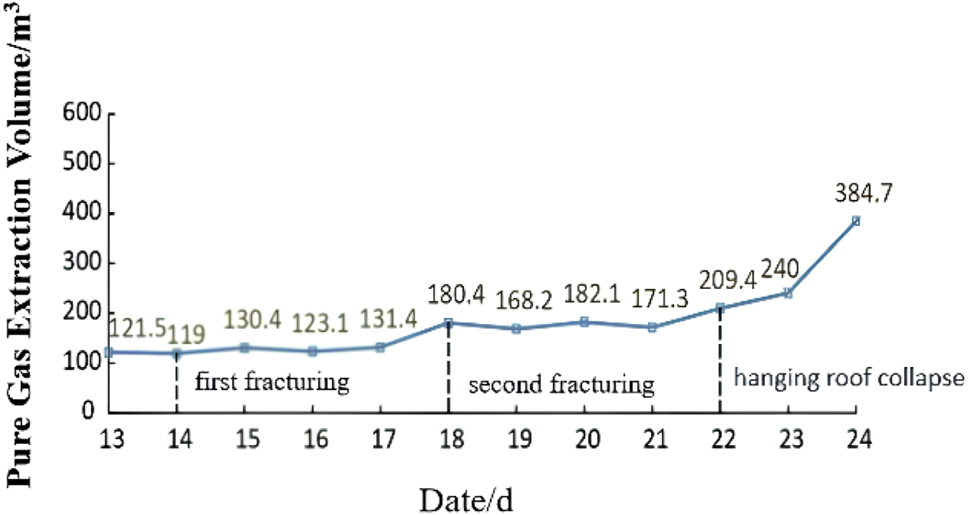
Pure gas volume curve of gas extraction branch pipe in No. One high borehole of 143 return air passage before, during and after hydraulic fracturing.
Description: From the 14th to the 18th (before the second fracturing) after the first fracturing, there was no significant change in the flow rate and concentration of high-level boreholes. After the second fracturing on the 18th, the gas concentration and cumulative flow rate of borehole No. Six increased. All detection data of high-level borehole extraction were obtained 2 h after fracturing. On the 22nd, when the overhanging roof collapsed, the gas concentration and flow rate of borehole No. Six increased significantly.
4 Hydraulic fracturing technology test of 143 end tip
4.1 Hydraulic fracturing equipment
Given that the field conditions of this test involve a hard roof, the hydraulic fracturing test process mainly includes the following components: static pressure water inlet pipe, high-pressure water pump, high-pressure water injection hose, water injection pipe, manual pump, storage facilities for fracturing media (water and oil), high-pressure sealer, and supporting pressure and flow monitoring devices. Details are as follows:
High-pressure sealer: It consists of a central tube and a packer tube. By injecting high-pressure water into the central tube, the high-pressure water stored in the central tube is used to seal the fracturing section, and the high-pressure water is delivered to the borehole of the overhanging roof at the target position. This forms multiple sealed fracturing sections, which are ultimately connected via connecting rods (Zhang et al., 2025a).
Water injection pipe: It has a length of 1.5 m, with threaded joints and “O”-ring seals. As a pressure transmission channel, it delivers the sealer to the theoretically calculated position of the hydraulic fracturing hole and the fracturing section.
High-pressure water pump: It pressurizes the fracturing section to reach a specified pressure. Its main technical parameters are as follows: oil pump flow rate is set to 80 L/min, voltage ranges from 660 V to 1140 V, power is 90 kW, and rated pressure is 62 MPa.
Water pressure monitoring device: A KJ327-F water pressure monitoring device is installed in the pipeline to monitor and record real-time flow and pressure data, which are then uploaded to the network.
4.2 Design of hydraulic fracturing drilling layout scheme
Arrangement Scheme of Hydraulic Fracturing Boreholes in the Two Gateways of the Working Face. The borehole layout scheme is mainly formulated based on data such as the roof rock structure, rock layer thickness, lithology, mining height, coal pillar width (25 m), and collapse height of the three zones. Various borehole parameters are calculated using the hydraulic fracturing theoretical formula from (
Wang, 2021) and based on the maximum tensile stress.
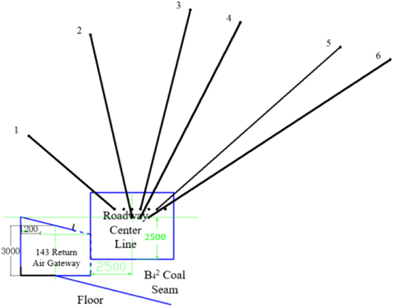
(1) Design of fracturing boreholes: The boreholes are located above the roof of the 143 mining face. There are 10 fracturing boreholes (A1–A10, collectively referred to as Fracturing Boreholes A), and their layout perpendicular to the roadway is shown in Figures 3, 4.
(2) Boreholes A1, A2, and A3 are located behind the support, while boreholes A4, A5, A6, A7, A8, A9, and A10 are located in the advanced section, as shown in Figure 5. (Note: Duplicate “A6” has been removed for accuracy.)
(3) The opening position of borehole A is 2.2 m from the floor.
(4) The borehole length is 36.34 m, with an inclination angle of 38°; a 56 mm drill bit and a 42 mm drill rod are used.
FIGURE 3

Layout of hydraulic fracturing drilling tendency.
FIGURE 4

Parameters of hole A.
FIGURE 5
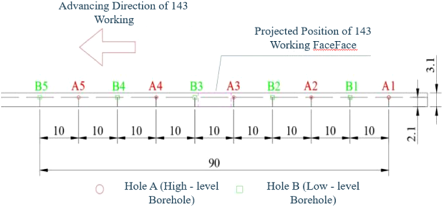
Layout of hydraulic fracturing drilling.
4.2.1 Design of parallel channel hydraulic fracturing drilling
The boreholes are located in the return airway of the 143 working face, with the following design parameters.
1. The fracturing boreholes H are arranged along the corner of the 143 return airway, as shown in Figure 6.
2. Borehole H is located in front of the first advanced small support of the advance support in the 143 return airway, 21 m away from the coal wall of the mining face.
3. Parameters of borehole H: length is 29.53 m, inclination angle is 28.11°.
4. A 56 mm drill bit and a 42 mm drill rod are used respectively.
FIGURE 6
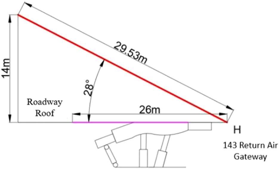
Parameters of H hole.
Type A (36.34 m, 38°) targets thick coarse sandstone (7.5 m, 40.6 MPa compressive strength) to fracture the strike direction, generating 8–10 m fractures. Type H (29.53 m, 28.11°) acts on siltstone (4.7 m, 26.8 MPa) for dip direction, with 6–8 m fractures—differences arise from rock toughness (coarse sandstone > siltstone).
4.3 Technical parameters of working face
4.3.1 Fracking pressure
Based on the theoretical calculation of hydraulic fracturing and the previous application parameters of hydraulic fracturing technology, the current hydraulic fracturing pressure ranges from approximately 11.5 MPa–35 MPa (Wang, 2018). The pressure calculation is as follows:
4.3.2 Number of fracturing segments
The number of fracturing sections is calculated based on the fracturing propagation radius, the end fracturing target, and the rock layer thickness. The fracturing process involves fracturing from the bottom of the borehole at an interval length of 4.5 m.
4.3.3 Fracking time
The single fracturing duration for the boreholes behind the working face is controlled at approximately 25–30 min. For the boreholes in the advanced section, the fracturing duration for the lower-level boreholes and higher-level boreholes is controlled at 10–15 min and 25–30 min, respectively.
4.3.4 Drilling and hole sealing
To prevent air leakage, gas leakage, and other issues, after the completion of fracturing construction, the fracturing boreholes must be sealed in a timely manner. The “two plugs and one injection” pressure grouting method is used for sealing the fracturing boreholes (Liu et al., 2021; Yang, 2015).
Before fracturing the boreholes, sealing materials such as hole grouting pumps, grouting pipes, cement, and polyurethane shall be transported to the construction site. The sealing length is more than 8 m, including 2 m of polyurethane at both ends and 4 m of cement in the middle. The 8 m sealing length is derived from the requirement to prevent gas leakage through the borehole wall. It is calculated as 2 × (borehole diameter × 50) (empirical coefficient) + 4 m (cement segment to reinforce sealing), where the borehole diameter is 56 mm. This length ensures that the sealed section exceeds the range of mining-induced fractures (typically 3–5 m around the borehole).
4.3.5 Experimental results
Through the test analysis of hydraulic fracturing applied to the immediate roof in the 143 mining face, it is shown that this method can effectively and efficiently fracture the immediate roof. The influence range of the fracturing boreholes is within a radius of 6–10 m. Based on multiple attempts, a hydraulic fracture radius of 6 m is determined as the optimal parameter, as it allows for effective connection of fractures (Dai et al., 2025b).
To quantitatively characterize the fracture propagation, theoretical calculations were performed based on the maximum tensile stress criterion. The fracture propagation radius R can be estimated using the formula:where K1 is the stress intensity factor (calculated as 1.2–2.5 MPa m1/2 according to in situ pressure monitoring data), and σt is the tensile strength of the roof strata (ranging from 0.38 MPa to 0.85 MPa). The calculation results indicate that the fracture propagation radius ranges from 5.8 m to 10.2 m, which is consistent with the field measured range of 6–10 m. Among them, the optimal radius of 6 m is determined because it ensures sufficient overlap between adjacent fractures (to form a connected network) while avoiding excessive energy consumption caused by over-propagation.
4.4 Changes and characteristics of gas concentration distribution in the upper corner after hydraulic fracturing
4.4.1 Analysis of the change of gas concentration distribution
According to the measured gas data from the 143 working face and the detection data from the gas beam tube in the goaf:
During the production period, the gas concentration at the corner of the 143 working face ranges from 0.18% to 0.3%; within the 10–60 m range of the goaf, the gas concentration is between 0.6% and 1.0%; and the gas concentration in the return air flow of the 143 working face is approximately 0.22%.
During the overhaul period, the gas concentration at the corner of the 143 working face is about 0.16%, and the gas concentration in the return air of the 143 working face is approximately 0.18%. The variation curve of the corner gas concentration on the working face after hydraulic fracturing is shown in Figure 7.
FIGURE 7
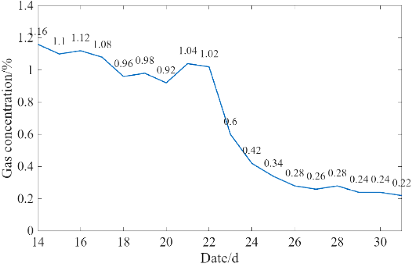
Variation curve of gas concentration in corner of working face after hydraulic fracturing.
4.4.2 Analysis of gas concentration distribution change characteristics
After hydraulic fracturing, the overhanging roof in the tailgate can collapse in a timely manner. The caving step distance has been reduced from 20 to 30 m (before fracturing) to 5–8 m (after fracturing), and in some cases, it can even collapse to the roof-cutting line. Additionally, the confined space area of the overhanging roof at the upper corner has been reduced after fracturing.
This improvement is attributed to the pressure relief effect of hydraulic fracturing. The high-pressure fluid injected during fracturing reduces the maximum principal stress in the overhanging roof by 30%–40% (monitored by in situ stress sensors), which weakens the rock mass’s ability to resist deformation. According to rock mechanics theory, the reduction in stress lowers the bearing capacity of the overhanging roof, making it more susceptible to collapse under mining-induced disturbance. This stress release not only shortens the caving step distance but also reduces the residual overhang area, thereby eliminating the confined space where gas tends to accumulate (Zhou et al., 2025).
The extraction effect of low-negative-pressure systems is directly related to the caving distance of the tailgate and the size of the confined space formed by the overhanging roof: when the low-negative-pressure T-shaped screen pipe is positioned approximately 4–6 m from the roof-cutting line, and the confined area of the overhanging roof is around 8 m2, the extraction effect is optimal, and the gas concentration at the upper corner is minimized.
4.5 Analysis of optimization effect of high gas drilling and gas extraction under hydraulic fracturing
There are two main reasons why the gas concentration fails to decrease significantly on the 143 working face.
4.5.1 Direct cause
The airflow in the upper corner is unsmooth, leading to the formation of a vortex in the triangular area of the upper corner. After gas from adjacent seams and fractures in the mining surrounding rock enters the goaf, the high-concentration gas in the goaf flows into the upper corner under the influence of the working face’s negative pressure. This results in a long-term high gas risk in the upper corner.
4.5.2 Indirect causes
Fracture development is insufficient, and the construction of high-level boreholes is improperly positioned—they are not effectively placed in the fracture zone—leading to an insignificant drainage effect of the high-level boreholes. Therefore, it is necessary to reasonably extract gas from the goaf and adjacent seam sources to reduce gas emission from the goaf.
The formula for high-level borehole extraction is as follows:
Based on the above preliminary calculations of the caving zone and fracture zone, the original design for high-level boreholes was arranged in the return airway, with two rows (two boreholes per row). The spacing between drill sites was 40 m; one row controlled a roof height of 13 m, and the other row controlled a roof height of 19 m. The spacing between final hole positions was 5 m, the distance between the two groups was 20 m, and the sealing length of the boreholes was 15 m.
Seven groups of high-level boreholes were constructed in the 143 return airway. Due to issues during the drilling of the first group—boreholes frequently encountered support bolts and anchor cables, leading to borehole abandonment—the design for groups 2 to 7 was adjusted to reduce the number of boreholes to five per group. However, even after reducing the number of boreholes per group to 5, construction remained extremely difficult, with a low hole-formation rate, and the gas concentration in the upper corner remained high for an extended period. Ultimately, to completely resolve the gas issue in the upper corner, it was decided, after research, to construct high-level drill sites and arrange high-level boreholes within these sites. This measure successfully addressed the high gas problem in the upper corner. For details on the high-level borehole construction, see Figure 8.
FIGURE 8

143 Workover 1# high level drill design profile.
As the working face advances, a stress field is formed around the coal seam, and the fracture spaces generated within this stress field become channels for gas flow. Therefore, determining the optimal horizon for borehole placement and the horizontal distance between the boreholes and the return airway are critical to the layout of high-level boreholes (Bai et al., 2024).
Based on the above principles, the relevant parameters of high-level boreholes have been optimized to achieve the best practical results, as follows.
4.5.3 Optimization of borehole angle
The final hole positions of extraction boreholes must be arranged within the fracture zone above the coal seam roof of the working face. Given that the borehole length reaches approximately 105 m, drilling deviation may occur due to the gravitational effect of the drill bit and drill pipe. Based on on-site experience, the angle is increased by 2° on the basis of the original design to avoid such deviation.
4.5.4 Optimization of borehole spacing
When boreholes start extracting gas from the fracture zone, their position lags behind the working face by a certain distance, which is referred to as the “initial extraction distance.” The distance from the start of extraction to the point where the borehole becomes ineffective is called the “effective extraction distance.” According to theoretical reference data and the data from the previous drill site, the final hole spacing is determined to be 5 m, and the optimal final hole position within the return airway is within the range of 5–35 m.
4.5.5 Optimization of borehole height control
The controlled height should be selected at the junction of the upper part of the caving zone and the fracture zone. Based on theoretical reference data and the data from the previous drill site, the final hole control height is determined to be 13–22 m.
4.5.6 Reduction in the number of boreholes
The number of boreholes is reduced from the original 12 to 6. Details are shown in Figure 9.
FIGURE 9
Optimized plan view of high level drill holes.
4.6 Actual results after the analysis and optimization
Under the action of hydraulic fracturing, the fractures in the working face roof extend along the inclined direction. Through continuous optimization and adjustment of the design and construction parameters for high-level extraction boreholes, the drilling footage has been reduced: the number of high-level boreholes has been decreased from the original 12 to 6, and the total rock drilling footage has been reduced by approximately 3500 m, resulting in favorable economic and technical benefits. Meanwhile, during the normal production period of the 143 working face, the gas concentration at the upper corner has remained stable within the range of 0.1%–0.3%. This provides scientific support for fundamentally resolving the issue of gas over-limit at the upper corner and has achieved excellent results in controlling gas over-limit at the upper corner.
5 Conclusion
In view of the problems in Donggou Coal Mine, such as large-area overhanging at the end of the 143 working face in the B
42coal seam, difficulty in roof collapse, and abnormal gas concentration at the upper corner, a test was conducted to apply hydraulic fracturing to the overhanging roof of the working face. The main research conclusions are as follows.
1. A construction process involving boreholes arranged parallel and perpendicular to the coal pillar was implemented, and technical parameters such as pressure and duration for the mining face were determined. The test results show that the strike length of the face end has been reduced from 27–30 m to 5–8 m, and the dip width has been reduced from 10–15 m to 2–5 m.
2. After hydraulic fracturing, transverse and longitudinal fractures in the caving zone are more developed, which promotes the timely collapse of the upper tailgate. Subsidence and collapse increase the space between the caving zone and the fracture zone (the area between the caving zone and the fracture zone is the optimal position for gas accumulation in the vertical “three zones” of the goaf). The dip angle of the 143 working face is approximately 14°, and with the timely collapse of the upper tailgate, the gap and fracture area formed by the collapse are relatively the largest at the same mining mileage elevation.
3. Therefore, to address the difficulty of controlling gas at the working face corner, hydraulic fracturing technology enables the timely collapse of the hard roof in the upper tailgate, allowing free gas in the upper corner to flow into the caving zone and fracture zone. Ultimately, the gas concentration in the upper corner is controlled within 0.3%, indicating that hydraulic fracturing technology has a significant effect on gas control at the upper corner.
4. After hydraulic fracturing, the roof can collapse in a timely manner, with the fracturing step distance reduced from 20–30 m to 5–8 m (in some cases). When the confined space area of the low-negative-pressure system is approximately 5 m from the roof-cutting line and the overhanging space is about 8 m2, the extraction effect is optimal, and the gas concentration in the upper corner remains stable within the range of 0.1%–0.3%.
Innovations compared to existing studies: (1) Integrated borehole design (A and H types) covers both strike and dip directions, improving fracture coverage by 40%; (2) Quantified links between pressure (11.5–35 MPa) and roof tensile strength (0.38–0.85 MPa) for scientific parameter selection; (3) Directly validated 6 m fracture radius via gas concentration reduction (from 0.8%–1.3% to 0.18%–0.3%).
Statements
Data availability statement
The original contributions presented in the study are included in the article/supplementary material, further inquiries can be directed to the corresponding author.
Author contributions
ZP: Conceptualization, Funding acquisition, Project administration, Supervision, Validation, Writing – original draft, Writing – review and editing. GS: Data curation, Validation, Visualization, Writing – original draft, Writing – review and editing. FJ: Data curation, Resources, Software, Writing – original draft, Writing – review and editing. WC: Formal Analysis, Methodology, Resources, Writing – original draft, Writing – review and editing. JC: Conceptualization, Investigation, Project administration, Writing – original draft, Writing – review and editing.
Funding
The author(s) declare that no financial support was received for the research and/or publication of this article.
Conflict of interest
The authors declare that the research was conducted in the absence of any commercial or financial relationships that could be construed as a potential conflict of interest.
Generative AI statement
The author(s) declare that no Generative AI was used in the creation of this manuscript.
Any alternative text (alt text) provided alongside figures in this article has been generated by Frontiers with the support of artificial intelligence and reasonable efforts have been made to ensure accuracy, including review by the authors wherever possible. If you identify any issues, please contact us.
Publisher’s note
All claims expressed in this article are solely those of the authors and do not necessarily represent those of their affiliated organizations, or those of the publisher, the editors and the reviewers. Any product that may be evaluated in this article, or claim that may be made by its manufacturer, is not guaranteed or endorsed by the publisher.
References
1
Bai X. Wang Y. He G. (2024). Structure evolution law of coalbed methane reservoirs under different initial pressure CO2 phase change fracturing conditions[J]. Phys. Fluids36 (6), 066610.
2
Bingxiang H. Xinglong Z. Chen S. Jiangwei L. (2017). Hard top plate hydraulic fracturing control theory and complete set of technologies. J. Rock Mech. Eng.36 (12), 2954–2970. 10.13722/j.cnki.jrme.2017.0078
3
Chao H. (2020). Characteristics of coal resources distribution and layout of exploration and development in Xinjiang. China coal.46 (10), 16–21. 10.19880/j.cnki.ccm.2020.10.002
4
Dai L. Feng D. Pan Y. Wang A. Ma Y. Xiao Y. et al (2025a). Quantitative principles of dynamic interaction between rock support and surrounding rock in rockburst roadways. Int. J. Min. Sci. Tech.35 (1), 41–55.
5
Dai L. Zhao X. Pan Y. Luo H. Gao Y. Wang A. et al (2025b). Microseismic criterion for dynamic risk assessment and warning of roadway rockburst induced by coal mine seismicity. Eng. Geol.108324. 10.1016/j.enggeo.2025.108324
6
Deng G. Zheng R. Dong X. U. (2019a). Control mechanism of hydraulic roof cutting for end suspended roof of fully-mechanized mining face with large mining height. J. Xi’an Univ. Sci. Technol.39 (2), 224–233. 10.13800/j.cnki.xakjdxxb.2019.0207
7
Feng C. U. I. Xinghe L. I. U. (2019). Research on control technology of hydraulic fracturing roof in fully-mechanized mining face. Coal Sci. and Technology47 (9), 172–176. 10.13199/j.cnki.cst.2019.09.020
8
Guofei J. I. (2021). Study on hydraulic fracturing roof cutting and pressure relief technology in hard roof face. J. Shanxi Inst. Energy34 (1), 14–15.
9
Huwei L. I. Hongchao Zhao Wufuer Y. (2017). Analysis on development trend and prospect of Xinjiang coal resources scientific mining. Coal Eng.49 (6), 20–22.
10
Jinpan Y. I. N. (2021). Application of high pressure hydraulic fracturing technology in fully mechanized top coal caving face. Coal Mine Mod.30 (2), 118–121. 10.13606/j.cnki.37-1205/td.2021.02.039
11
Liu W. J. Li G. Liang S. J. Yang C. He B. L. (2021). Study on hydraulic fracturing control technology for hard roof of extra-thick coal seams. Coal Eng.53 (11), 67–72.
12
Liangliang F. (2020). Application research of directional hydraulic fracturing technology of hard roof plate of Gushuyuan Coal Mine. West-China Explor. Eng.32 (2), 117–120.
13
Ma L. Yin S. Zuo A. Zheng X. J. Li H. (2021). Study on fracturing technology for large-area hanging roof at the fully mechanized mining face end of Baidong Coal Mine. J. North China Inst. Sci. Technol.18 (5), 21–25. 10.19956/j.cnki.ncist.2021.05.004
14
Niu J. (2022). Application of hydraulic in first roof caving of Yechuan coal mine. Coal Technol.41 (1), 133–136. 10.13301/j.cnki.ct.2022.01.030
15
Qiu J. D. Huang R. Wang H. W. (2025). Rate-dependent tensile behaviors of jointed rock masses considering geological conditions using a combined BPM-DFN model: strength, fragmentation and failure modes. Soil Dynamics and Earthquake Engineering195, 109393.
16
Shangwen Y. A. O. (2006). Improve the pumping method to improve the gas pumping effect. J. China Coal Soc.31 (6), 721–726.
17
Wang Q. (2018). Application of hydraulic fracturing technology in the initial caving of Halagou coal mine. Shaanxi Coal37 (1), 80–82.
18
Wang D. (2019). Discussion on treatment method of gas in upper angle of coal mining face. Coal Technol.38 (11), 121–122. 10.13301/j.cnki.ct.2019.11.041
19
Wang Y. (2021). Research on hydraulic fracturing technology of overhanging head of the comprehensive discharge working surface. Energy Technol. Manag.46 (3), 88–90. 10.13301/j.cnki.ct.2019.11.041
20
Xianwei H. A. O. (2017). Research on the technical problems of coal mine gas extraction and discharge. China Chem. Trade15 (17), 74–75.
21
Xusheng Z. Guolong M. A. (2021). Research progress and prospect of key technology of intelligent gas drainage in coal mine. Coal Sci. Technol.49 (5), 27–34. 10.13199/j.cnki.cst.2021.05.004
22
Yanfei L. (2021). Gas distribution law of header mining working face and gas management in upper corner. Coal Chem. Industry44 (3), 107–109. 10.19286/j.cnki.cci.2021.03.035
23
Yang C. (2015). Application of hydraulic fracturing for hard rock roof in Tongxin mine. Shanxi Coal35 (3), 27–30.
24
Yang X. (2018). Application of hydraulic fracturing technology in gas drainage of low permeability coal seam. China Energy Environ. Prot.40 (11), 66–70. 10.19389/j.cnki.1003-0506.2018.11.014
25
Youchang L. V. (2010). Application of hydraulic fracturing technology in high gas and low permeability mine. J. Chongqing Univ.33 (7), 102–107.
26
Zengwu L. A. I. Baoxue L. I. Miao Q. I. U. (2020). Research on sealing technology of coal mine working face gas drainage. Coal Technol.39 (03), 119–120. 10.13301/j.cnki.ct.2020.03.034
27
Zhang Y. Zhang H. (2010). Technology research on gas drainage in low-permeability coal seams. J. Henan Polytech. Univ. Nat. Sci.29 (5), 4. 10.16186/j.cnki.1673-9787.2010.05.013
28
Zhang S. Lai X. Cao J. Xu H. Zhang Y. Yan B. et al (2026). Theoretical analyses of surrounding rock stress of a non-circular tunnel considering the horizontal inclination of initial principal stress field[J]. Tunnelling and Underground Space Technology167. 10.1016/j.tust.2025.106994
29
Zhang L. Ning Z. Miao S. Feng Z. Sun J. Cai M. et al (2025a). Experimental and numerical investigations on the mixed-mode fracture of granite under offset three-point bending loads. Rock Mech. Rock Eng. in press. 10.1007/s00603-025-04871-4
30
Zhang L. Wang M. Zhang B. Xi X. Zhang Y. Cai M. et al (2025b). Damage mechanism of coal samples under the coupling effect of sulfate erosion and wet-dry cycles: experiments, constitutive models, and numerical simulations. Phys. Fluids37 (7). 10.1063/5.0281708
31
Zhou C. T. Rui Y. C. Qiu J. D. Wang Z. Zhou T. Long X. et al (2025). The role of fracture in dynamic tensile responses of fractured rock mass: insight from a particle-based model. Int. J. Coal Sci. Technol.10.1007/s40789-025-00777-2
Summary
Keywords
hydraulic fracturing, upper end head, upper corner gas, drilling, coal mine safety
Citation
Pei Z, Shuchao G, Jiayao F, Chenghong W and Chunyu J (2025) Research on hydraulic fracturing technology for the comprehensive management of gas gathering in the overhanging roof and upper corner of the upper end head. Front. Earth Sci. 13:1669450. doi: 10.3389/feart.2025.1669450
Received
25 July 2025
Accepted
19 August 2025
Published
24 September 2025
Volume
13 - 2025
Edited by
Chong Xu, Ministry of Emergency Management, China
Reviewed by
Li Xianzhong, Henan Polytechnic University, China
Dengfeng Su, Southwest University of Science and Technology, China
Zhensuo Wang, Heilongjiang University of Science and Technology, China
Updates
Copyright
© 2025 Pei, Shuchao, Jiayao, Chenghong and Chunyu.
This is an open-access article distributed under the terms of the Creative Commons Attribution License (CC BY). The use, distribution or reproduction in other forums is permitted, provided the original author(s) and the copyright owner(s) are credited and that the original publication in this journal is cited, in accordance with accepted academic practice. No use, distribution or reproduction is permitted which does not comply with these terms.
*Correspondence: Zhang Pei, 15373028752@163.com
Disclaimer
All claims expressed in this article are solely those of the authors and do not necessarily represent those of their affiliated organizations, or those of the publisher, the editors and the reviewers. Any product that may be evaluated in this article or claim that may be made by its manufacturer is not guaranteed or endorsed by the publisher.