 Ke Li1
 Rui Yang
- 1CCCC Second Harbor Engineering Company Ltd., Wuhan, China
- 2Department of Civil and Environmental Engineering, University of Strathclyde, Glasgow, United Kingdom
Introduction: Lattice-shaped diaphragm walls (LSDWs) are increasingly used in bridge foundations and foundation pit enclosures due to their high vertical and horizontal load-bearing capacity. Unlike conventional diaphragm walls that mainly support vertical loads, LSDWs are predominantly subjected to horizontal forces during excavation. However, the lateral bending behavior of their joints—particularly perforated cross-plate joints (PCPJs)—remains insufficiently studied. This paper aims to investigate the lateral bending performance of single- and double-cross PCPJs, a critical joint type in LSDWs.
Methods: An experimental program was conducted involving eight sets of PCPJ specimens and one non-jointed wall segment. Four-point bending tests were carried out to analyze the influence of the steel plate perforation ratio on the load–displacement response and ultimate bearing capacity. Typical failure modes and mechanisms were identified, and a calculation method for the lateral bending capacity of PCPJs was proposed.
Results: The lateral bending failure of PCPJs was characterized by separation at the web–lower flange steel–concrete interface, fracture of the concrete dowel, and tensile cracking at the end of the steel plate flange. The bending capacities during the elastic stage reached 25.5% and 44.9% of the ultimate load for single- and double-cross PCPJs, respectively. The double-cross PCPJ exhibited higher lateral bending capacity than the single-cross type—approximately 1.6 times under the same perforation ratio—though still lower than the non-jointed segment. Additionally, lateral bearing capacity correlated positively with perforation ratio, with double-cross joints showing greater sensitivity to this parameter.
Discussion: The proposed calculation method for lateral bending capacity showed good agreement with experimental values, with deviations ranging from −2.16% to 6.20%, demonstrating its reliability. These findings provide important insights into the structural performance of PCPJs and offer a valuable reference for the design and application of LSDWs in similar engineering applications.
1 Introduction
A lattice-shaped diaphragm wall (LSDW) comprises front walls, rear walls, side walls that connect the ends of the front and rear walls, and internal partition walls. LSDWs offer a large wall-soil contact area and exhibit high vertical bearing capacity (Wu et al., 2020). Moreover, their overall bending resistance, horizontal bearing capacity, and seismic performance are significantly superior to those of pile group foundations (Japan Association of Diaphragm Wall, 2001; Wu et al., 2016a). These advantages have contributed to the growing adoption of LSDWs in bridge foundations and excavation support structures (Li W. et al., 2024; Li Z. et al., 2024).
Due to the construction characteristics of diaphragm walls, panel joints are an inevitable feature of LSDWs. However, prior research has predominantly focused on the overall stress performance of LSDWs and the wall-soil interaction mechanism, with limited attention given to the behavior of joints (Japan Association of Diaphragm Wall, 2001; Wu et al., 2016a; Li W. et al., 2024; Li Z. et al., 2024). Furthermore, unlike conventional diaphragm walls that primarily bear loads along the depth direction of the soil layer, LSDWs exhibit a distinct principal force direction. In LSDWs, the length-to-depth ratio is typically less than 1/3 (Cheng et al., 2012; Fu, 2022; Wu et al., 2016b; Zhou et al., 2011), resulting in a unidirectional plate configuration where the depth direction constitutes the long side and the horizontal direction serves as the primary load-resisting axis. Therefore, when soil excavation is involved, the LSDW joint must withstand greater lateral loads than vertical loads, which is a key reason why LSDWs typically adopt rigid joints (Wang et al., 2024). Joints can be categorized into rigid and flexible joints based on their ability to transmit bending moments and shear forces. The recommended rigid joints include I-shaped or cross-shaped perforated steel plate joints and rebar socket joints (JGJ 120-2012, 2012). However, the rigidity of these joints targets conventional diaphragm walls rather than LSDWs. In particular, more common perforated cross-plate joints (PCPJs) have rarely been studied in LSDWs.
Under horizontal loads, PCPJs are subjected to bending moments. Based on the mechanical behavior of steel-concrete composite structures, the lateral bending capacity of PCPJs may be influenced by the bond strength between the steel plates and concrete, as well as the performance of the concrete dowel. The bond strength between steel plates and concrete can be evaluated using push-out, pull-out, and splitting tests (Soh et al., 1999; Lee et al., 2011; Trad et al., 2024). Majdi et al. (Majdi et al., 2014), through pull-out tests, investigated thin-walled corrugated steel embedded in concrete with varying concrete strengths and established a bilinear bond-slip model by presenting the corresponding overall bond-slip curves. Walter et al. (Oguejiofor and Hosain, 1994) studied the normal stress-crack opening relationship at the steel-concrete interface via wedge-shaped splitting tests. They reported that the failure of the steel-concrete interface exhibited quasi-brittle characteristics. However, research on concrete dowels has focused mainly on the shear characteristics of perforated steel plate shear keys. Oguejiofor et al. (Al-Darzi et al., 2007; Ahn et al., 2010; Kim et al., 2018) derived a formula for calculating the shear bearing capacity of perforated steel plate shear keys through push-out test fitting. However, owing to the presence of transverse rebar, the shear mechanism and shear capacity of perforated steel plate shear keys are different from those of perforated steel plates. Wang (Wang et al., 2022) compared shear keys with and without transverse rebar through experiments and reported that the shear of concrete dowel dominated the failure of shear keys without transverse rebar, whereas the shear keys with transverse rebar were dominated by rebar. Moreover, the ultimate shear stiffness of the shear keys with transverse rebar was 2.12 times greater than that in the case without transverse rebar. Chen et al. (Chen et al., 2016a; Chen et al., 2016b) studied the vertical shear behavior of conventional diaphragm wall PCPJs through shear tests and numerical simulations. The results indicated that the perforation ratio influences the bearing capacity of PCPJs, the shear strength of the concrete, and the stiffness of the steel plates. The shear bearing capacity of perforated steel plate shear keys was found to be 1.8 to 4.4 times greater than that of PCPJs, and the existing shear bearing capacity formulas applicable to the former were inadequate for the latter, necessitating targeted modifications. In summary, the limited existing research on PCPJs has primarily focused on shear bearing capacity. Although factors potentially affecting the lateral bending capacity of PCPJs—such as steel-concrete interfaces and concrete dowels—have been explored, the specific mechanisms through which these factors influence bending performance remain unclear.
This study focused on the Fuchi Ship Lock project, the first in China to implement an LSDW as the lock wall. Nine sets of scaled four-point bending tests, with a similitude ratio of 1:3, were conducted on single-cross and double-cross PCPJs within the LSDW to investigate the influence of the steel plate perforation ratio on the lateral bending bearing capacity of PCPJs. The lateral bending failure mechanisms of PCPJs were identified, and a corresponding method for calculating the bending bearing capacity was proposed. The computed results aligned well with the experimental data, offering a valuable reference for the design of PCPJs in LSDWs.
2 Project background
The Fuchi Ship Lock chamber features a composite lock wall structure comprising an upper hollow box retaining wall and a lower LSDW. The LSDW measures 21.6 m in height, 144.4 m in length, and 1.2 m in thickness. The net spacing between the front and rear walls is either 10 m or 8.35 m. The diaphragm wall panels consist of various configurations, including I-shaped, L-shaped, T-shaped, and Z-shaped panels, with lengths ranging from 5.3 m to 11.7 m, as illustrated in Figure 1a. The diaphragm wall penetrates 5 m into the bedrock, with a 1.8 m penetration below the karst cave, as shown in Figure 1b.
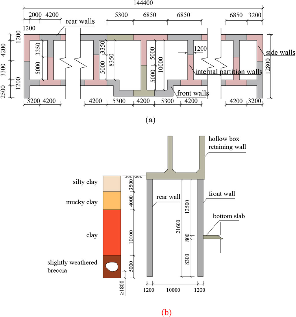
Figure 1. Structural diagrams of the diaphragm wall (unit: mm). (a) LSDW plan. (b) Lock wall elevation.
The joints between the front and rear walls employ a single-cross PCPJ configuration, characterized by a 20 mm-thick cross steel plate flange, a 16 mm-thick web plate, and 32 mm-diameter horizontal and vertical rebars. The horizontal rebars of the primary panel are welded to the steel plate through equal-leg angle steel, with a 150 mm spacing between the reinforcement cages of the primary and secondary panels. Both panels have a flange length of 800 mm. The flange is perforated with eight rows of square holes, each measuring 120 mm × 120 mm, with a net spacing of 60 mm between holes. The joints of the lattice wall employ a double-cross PCPJ configuration. The double-cross steel plate flange lengths are 430 mm for the primary panel and 800 mm for the secondary panel, with a net spacing of 300 mm between the flanges in the panel width direction. The horizontal rebars of the primary panel are welded to the steel plate using connecting plates. Additionally, a stiffening plate is installed every 1,000 mm between the connecting plate and the web plate. All other structural details are consistent with those of the single-cross PCPJ, as illustrated in Figure 2.
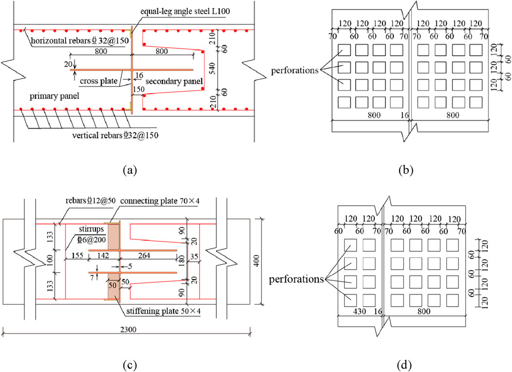
Figure 2. PCPJ construction drawings (unit: mm). (a) Schematic of a single-cross PCPJ. (b) Elevation of a single-cross PCPJ. (c) Schematic of a double-cross PCPJ. (d) Elevation of a double-cross PCPJ.
3 Experimental overview
3.1 Experimental design and parameters
Based on the background of the Fuchi Ship Lock project, single- and double-cross PCPJs with a vertical length of 1 m. A 1:3 scale ratio was adopted in accordance with the similarity theory for structural model tests. Geometric dimensions were scaled down by 1/3. Material properties were kept consistent with the prototype: the concrete strength grade C30 and steel elastic modulus matched the prototype materials, ensuring strength equivalence. The main rebar had a diameter of 12 mm and a spacing of 50 mm. The effect of the vertical reinforcement in the prototype was not considered in this study. Stirrups with a diameter of 6 mm and a spacing of 200 mm were provided and arranged to avoid the region of the cross steel plate. The steel plate flange and web had thicknesses of 7 mm and 5 mm, respectively. The vertical reinforcement was neglected in the test because the experiment focused on the lateral bending behavior of the joints, and the vertical reinforcement contributes minimally to lateral bending resistance. Both the single- and double-cross PCPJs were connected to the main reinforcement bars by welding with equal-leg angle steel, as illustrated in Figure 3.
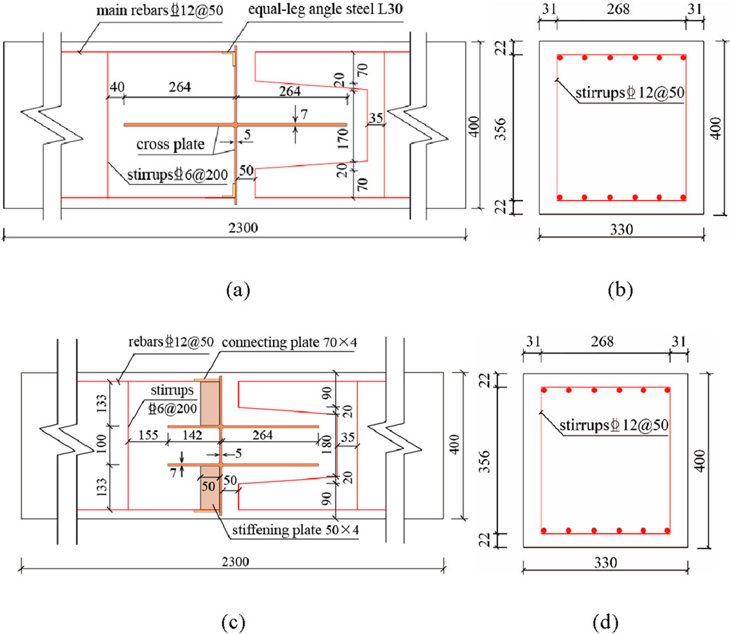
Figure 3. Specimen diagrams (unit: mm). (a) Elevation of a single-cross PCPJ specimen (b) Section of a single-cross PCPJ specimen. (c) Elevation of a double-cross PCPJ specimen. (d) Section of a double-cross PCPJ specimen.
A total of 9 specimens were prepared for the experiment, among which the r-1 specimen was a comparative non-joint specimen. Its main rebar had a diameter of 12 mm and a spacing of 50 mm, and its stirrups had a diameter of 6 mm and a spacing of 200 mm. The steel plate opening size for the secondary panel of the PCPJs was 40 mm × 40 mm. The number of openings in the primary panel remained consistent with the design, while the secondary panel included 20, 16, 8, and 0 openings for specimens s-1 to s-4 and d-1 to d-4, respectively. The dimensions of the steel plates are provided in Figure 4. The perforation ratio is defined as the ratio of the open area in the secondary panel to the total area of the steel plate flange. Accordingly, the perforation ratios for specimens s-1 to s-4 and d-1 to d-4 were 38.4%, 30.7%, 15.3%, and 0%, respectively.
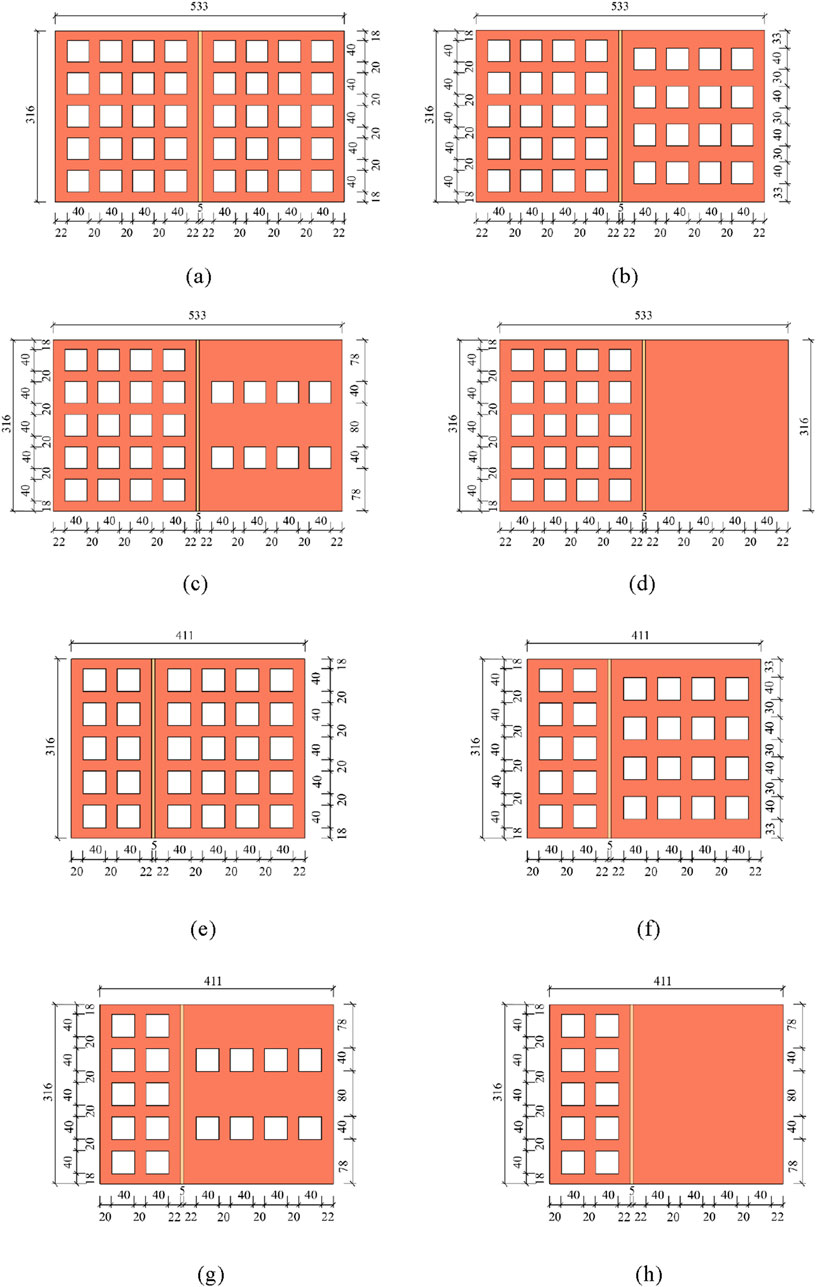
Figure 4. Flange dimension diagrams of the cross steel plate specimens (unit: mm). (a) Steel plate openings of specimen s-1. (b) Steel plate openings of specimen s-2. (c) Steel plate openings of specimen s-3. (d) Steel plate openings of specimen s-4. (e) Steel plate openings of specimen d-1. (f) Steel plate openings of specimen d-2. (g) Steel plate openings of specimen d-3. (h) Steel plate openings of specimen d-4.
3.2 Loading plan and layout of measuring points
The experiment utilized a 100 t multichannel servo loading system, which applied a load to the specimen via a distributing beam with a 700 mm spacing between loading points. Two hinge supports with spacings of 2,100 mm were arranged at the bottom of the specimen, as shown in Figures 5a,b.
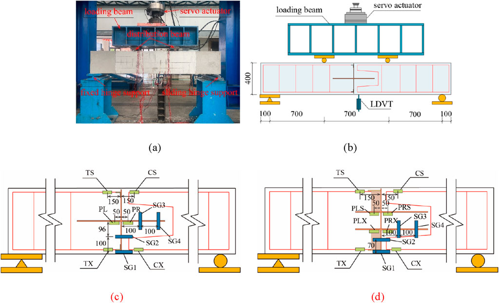
Figure 5. Specimen loading device and layout of the measuring points (unit: mm). (a) Experimental loading device. (b) Loading schematic. (c) Layout of measuring points for single-cross PCPJ specimens. (d) Layout of measuring points for double-cross PCPJ specimens.
The r-1 specimen was tested as a reinforced beam, representing a rigid joint with substantial bending capacity. The load increment for this specimen was set at 1 t per step. In contrast, the bending capacity of perforated cross-plate joints is significantly lower than that of the reinforced beam, with a load increment of 0.1 t per level for s-1–s-4 and d-1–d-4. After each load was held for 120 s and data stability was achieved, the next level of load was applied until the load on the actuator decreased.
The displacement sensor of the r-1 specimen was arranged in its mid-bottom, whereas the displacement sensors of the s-1–s-4 and d-1–d-4 specimens were arranged slightly right of the mid-bottom. The r-1 specimen was not equipped with strain gauges, whereas the s-1–s-4 and d-1–d-4 specimens were equipped with steel strain gauges (TS, CS, TX, CX) in the rebar area adjacent to the steel plate. One steel plate strain gauge (PL, PR) was installed on each side of the lower flange of the single-cross steel plate, adjacent to the web plate. The strain gauge arrangement for the double-cross steel plates followed the same configuration as the single-cross case, with gauges designated as PLS, PRS, PLX, and PRX. A total of four concrete strain gauges were employed: two (SG1 and SG2) were arranged horizontally at the lower part of the specimen to monitor the plain concrete between the steel plate and the M-shaped reinforcement bars; the remaining two gauges (SG3 and SG4) were positioned vertically on the right side, covering the right steel plate flange, as illustrated in Figures 5c,d.
4 Analysis of experimental results
4.1 Test phenomena and failure modes
The failure modes of the specimens are shown in Figure 6. The failure mode of the r-1 specimen is a typical failure mode of an under-reinforced beam. In the failure of single-cross PCPJ specimens, cracking initiates in the secondary panel, with a through-crack extending from the bottom of the specimen along the steel plate web to the end of the steel plate flange. This forms an L-shaped crack path that rotates 90° clockwise. Additional vertical or diagonal cracks appear at the end of the steel plate flange, as illustrated in Figures 6a–e. The failure mode of the double-cross PCPJ specimens is similar to that of the single-cross specimens, with a through-crack propagating from the specimen base along the steel plate web to the end of the lower flange, where diagonal cracks are also observed, as shown in Figures 6f–i.
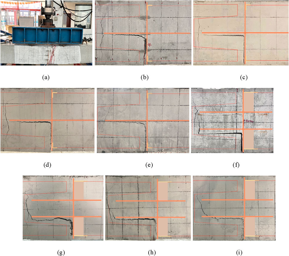
Figure 6. Specimen failure patterns. (a) Specimen r-1. (b) Specimen s-1. (c) Specimen s-2. (d) Specimen s-3. (e) Specimen s-4. (f) Specimen d-1. (g) Specimen d-2. (h) Specimen d-3. (i) Specimen d-4.
Here, we take s-1 as an example to explain the test phenomenon in the single-cross PCPJ loading process. First, initial cracks appear on the concrete surface near the lower steel plate web of the specimen (Figure 7a). As the load increases, the steel-concrete interface at the bottom of the specimen separates (Figure 7b). Lateral cracks develop near the interface between the lower surface of the steel plate flange and the adjacent concrete, extending toward the end of the flange (Figure 7c). Upon failure, the lower web of the steel plate detaches entirely from the concrete, forming a smooth splitting surface (Figure 7d). Complete separation occurs at the steel-concrete interface beneath the steel plate flange, accompanied by fracture of the concrete dowel within the flange opening and the formation of vertical cracks at the flange end (Figures 7e,f).
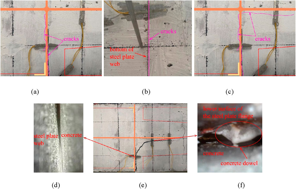
Figure 7. Typical test phenomena in a single-cross steel plate specimen. (a) Initial cracks. (b) Bottom cracks. (c) Cracks propagation. (d) Web-concrete interface. (e) Failure pattern. (f) Steel-concrete interface beneath the steel plate flange.
The test phenomena of the double-cross d-1 specimen during the loading process are similar to those of the single-cross s-1 specimen. The core difference is that failure of the flange steel-concrete interface occurs on the lower surface of the lower flange, and the fracture position of the concrete dowel is inside the lattice hole of the lower flange as shown in (Figures 8a–f).
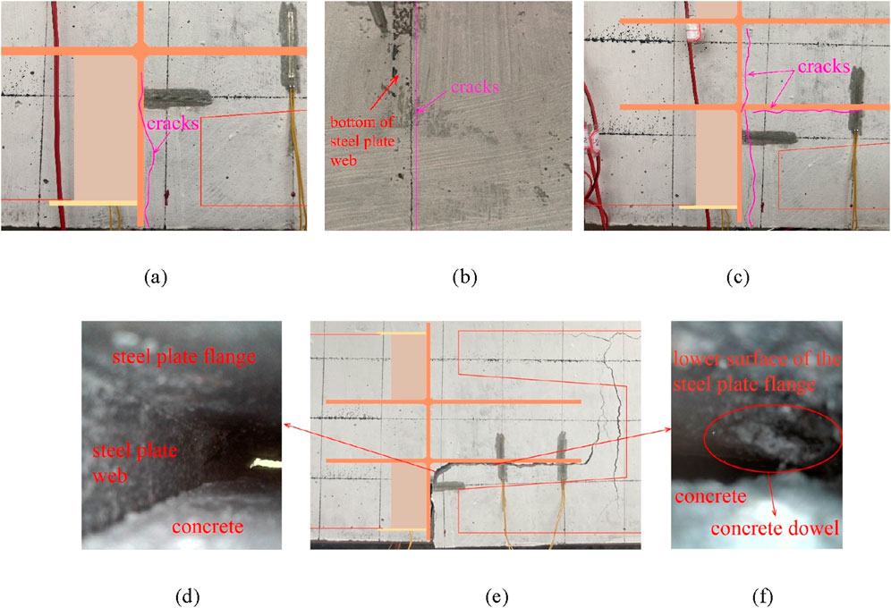
Figure 8. Typical test phenomena in a double-cross steel plate specimen. (a) Initial cracks. (b) Bottom cracks. (c) Cracks propagation. (d) Web-concrete interface. (e) Failure pattern. (f) Steel-concrete interface beneath the steel plate flange.
4.2 Analysis of load-vertical displacement curves
The PCPJ loading process in the four-point bending test can be divided into four stages: elastic, elastoplastic, failure descending, and residual, as shown in Figure 9a. The measured values of the critical loads for adjacent stages are denoted as
1. Elastic stage (OA): During this stage, the load displacement curve is almost a straight line, the specimen does not show any cracks, and no slip exists between the cross steel plate and the concrete.
2. Elastoplastic Stage (AB): This stage begins with the onset of separation at the steel plate-concrete interface near the bottom of the specimen, marked by a distinct step-like inflection point on the load-displacement curve. As the applied load increases, the lower web of the steel plate progressively detaches from the concrete, eventually leading to complete separation. Concurrently, the lower surface of the steel plate flange (the lower flange) begins to separate from the concrete. During this process, the slope of the load-displacement curve gradually decreases, continuing until the specimen reaches its ultimate bearing capacity.
3. Failure descending stage (BC): significant separation occurs between the steel plate and the concrete, with the separation surface forming an L shape that rotates clockwise by 90°. Moreover, the concrete dowel fractures in the hole of the steel plate flange (lower flange), resulting in vertical or diagonal tensile cracks near the flange end, and the specimen’s bearing capacity rapidly decreases.
4. Failure residual stage (CD): The width of the cracks in the concrete increases, and the measured mid-span deflection rapidly increases until the bearing capacity of the specimen becomes stable.
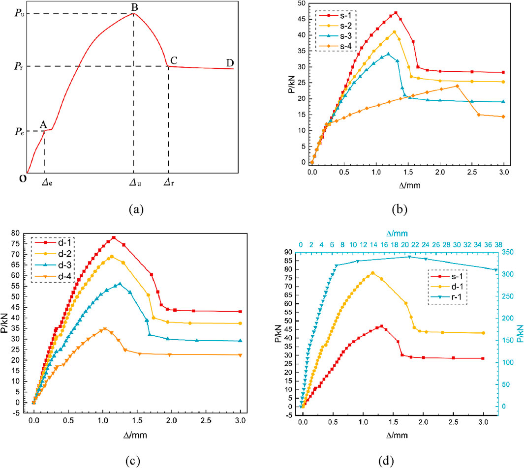
Figure 9. Load–displacement curves. (a) Typical load-displacement curves of PCPJs specimens. (b) Load-displacement curves of single PCPJs specimens. (c) Load-displacement curves of double PCPJs specimens. (d) Load-displacement curves of s-1, d-1 and r-1.
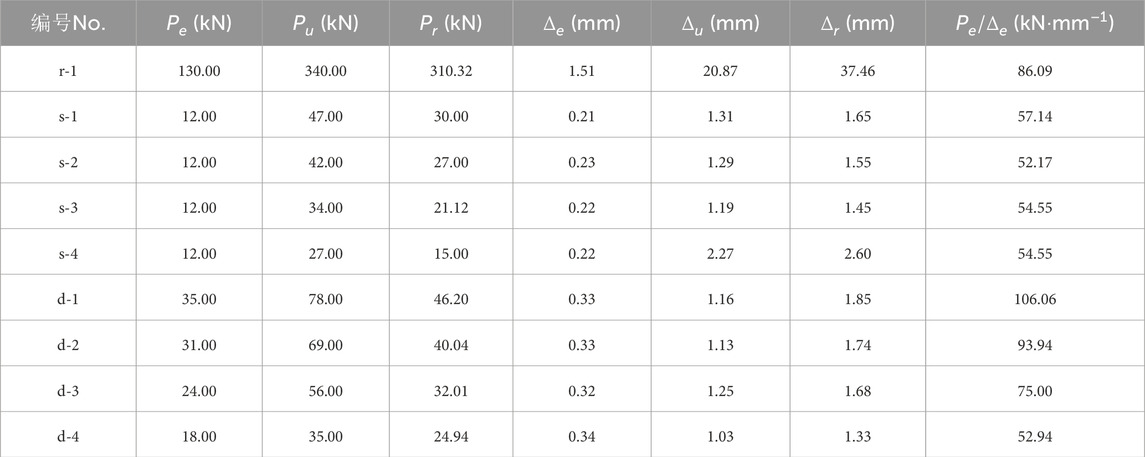
Table 1. Test results of the PCPJ lateral bending bearing capacity.
Figure 9 and Table 1 show that, compared with those of the nonperforated steel plate, with increasing perforation ratio, the bending capacities of the single-cross PCPJs increase by 41.67%, 70.83%, and 95.83%, respectively, whereas the bending capacities of the double-cross PCPJs increase by 60.0%, 97.14%, and 122.86%, respectively. This finding indicates that an increase in the perforation ratio can significantly improve the lateral bending capacity of joints, and the improvement is greater in the double-cross PCPJ case. The reason is that the concrete dowel has a greater bending contribution than the steel-concrete interface.
The bearing capacity ratios between the double-cross PCPJs and the single-cross PCPJs are 1.66, 1.68, 1.65, and 1.30 from high to low perforation ratios. These results reveal that double-cross PCPJs exhibit a greater bearing capacity than single-cross PCPJs, with an average of 1.57 times that of single-cross PCPJs. This is because the lower flange of the double-cross steel plate is further away from the neutral axis, where the bending contribution of the steel-concrete interface and concrete dowel is more significant.
The stiffness and
The
4.3 Steel plate strain analysis
The load-steel plate strain curves of each specimen in the elastic and elastoplastic stages are shown in Figure 10.
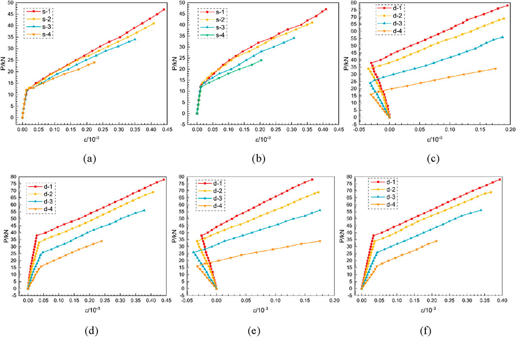
Figure 10. Load-steel plate strain curves. (a) PL. (b) PR. (c) PLS. (d) PLX. (e) PRS. (f) PRX.
As shown in Figure 10, the load-steel plate strain curves exhibit bilinear characteristics, and the load corresponding to the inflection point is almost the same as the
At a given load level, the load is
The maximum stress of the steel plate is 91 MPa, and the entire loading process is in the elastic stage.
4.4 Concrete strain analysis
The strains of the concrete in the elastic and elastoplastic stages are shown in Figure 11. The strain overflow in the figure is caused by the development of cracks in the concrete, leading to the fracture of the strain gauges.
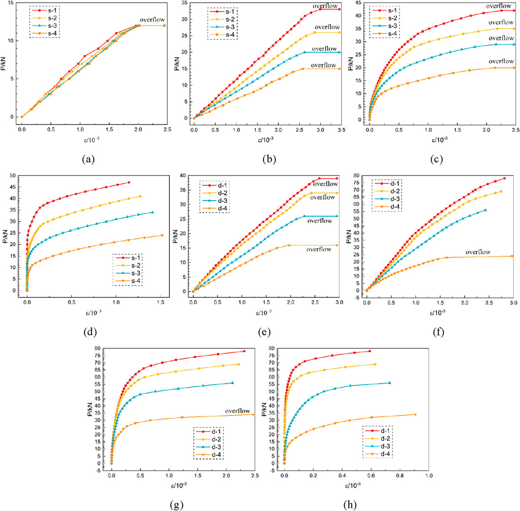
Figure 11. Load-concrete strain curves. (a) Single-cross steel plate SG1. (b) Single-cross steel plate SG2. (c) Single-cross steel plate SG3. (d) Single-cross steel plate SG4. (e) Double-cross steel plate SG1. (f) Double-cross steel plate SG2. (g) Double-cross steel plate SG3. (h) Double-cross steel plate SG4.
Figure 11 shows that under the same load increment, the strain slopes of SG2, SG3, and SG4 increase with increasing perforation ratio, indicating that the concrete dowel can delay the development of steel-concrete interface cracks. The strains recorded by SG4 do not exceed the measurement range, indicating that the steel plate flange does not fully detach from the concrete at the point of ultimate bearing capacity. Additionally, the load corresponding to the strain overflow of SG1 aligns with the transition point to the elastoplastic stage, confirming that the end of the elastic stage is marked by the separation of the lower web of the steel plate from the concrete.
Under identical loading conditions and with the same number of steel plate openings, the strains recorded by SG1–SG4 in double-cross PCPJs are lower than those observed in the single-cross PCPJ specimens. This can be attributed to the greater distance between the lower flange of the double-cross PCPJ and the neutral axis, as well as the tensile forces acting on the upper flange, which help to delay the separation of the interface between the lower flange steel plate and the concrete.
5 Calculation method for bending bearing capacity
5.1 Failure mechanisms
According to the experimental phenomena and data, the lateral bending failure mechanisms of the PCPJs are as follows:
1. The normal bonding strength at the steel-concrete interface is lower than the bonding strength between concrete aggregates. Under the action of bending moments, the lower web of the steel plate progressively detaches from the surrounding concrete. As a result, the neutral axis gradually shifts upward from the mid-height of the specimen, ultimately subjecting the cross steel plate flange to tensile forces.
2. When the steel plate flange-concrete region is subjected to bending and tensile forces, the strains in the steel plate and the concrete are equal. However, due to the elastic modulus of the steel plate being about seven times that of the concrete, the resulting stress difference is primarily resisted by two components: the tangential stress at the steel-concrete interface of the steel plate flange, and the shear resistance provided by the concrete dowel within the flange opening. As the stress differential increases, the concrete dowel undergoes shear failure, and the concrete begins to slide relative to the lower surface of the steel plate flange. This continues until the tangential cohesion at the interface reaches its maximum, at which point the corresponding bending moment defines the ultimate bearing capacity.
3. As the relative sliding between the concrete and the lower surface of the steel plate flange continues to increase, the tangential cohesion at the steel-concrete interface decreases. Concurrently, cracking develops in the concrete at the end of the flange, resulting in a rapid decline in bearing capacity until a stable residual value is achieved.
5.2 Simplified calculations and assumptions
We simplify the bearing capacity into the sum of two parts. Part I separates the steel plate web and the concrete, considering only the influence of the normal stress at the interface between the steel plate web and the concrete. Part II involves the separation between the lower surface of the steel plate flange and the concrete, as well as the tensile cracking of the concrete at the flange end. Considering the end section of the steel plate flange as the object of analysis, equilibrium is achieved through the combined effects of concrete stress, steel-concrete interface stress at the flange, and rebar stress, as illustrated in Figure 12. Due to the detachment of the steel plate web from the concrete, the stress level in the concrete beneath the flange (lower flange) is relatively low and therefore excluded from the analysis.
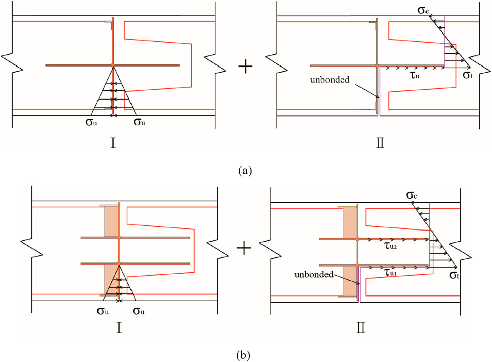
Figure 12. Simplified bearing capacity calculation models. (a) Single-cross PCPJ. (b) Double-cross PCPJ.
The following simplifications and assumptions are used when calculating the bearing capacity:
1. The influence of the differential biting force between the steel plate flange and the concrete on the bearing capacity of Part I is not considered.
2. The normal stress at the interface between the steel plate flange and the concrete is neglected.
3. The end section of the Part II flange is assumed to satisfy the plane section hypothesis.
4. When a PCPJ reaches its ultimate state, the biting force between the flange (lower flange) and the concrete attains its maximum value, and the stress distribution in the compressive and tensile zones of the concrete section is triangular.
5.3 Calculation method
The bearing capacity
The Part I bearing capacity
where
The simplified stress-strain distribution of Part II is shown in Figure 13.
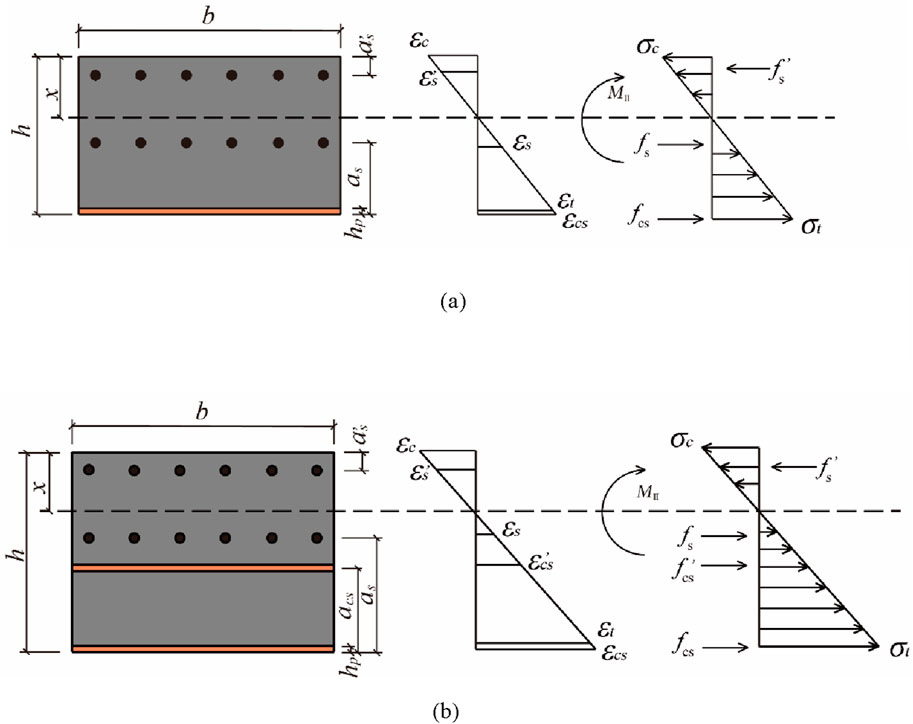
Figure 13. Stress-strain distribution maps of the failure sections. (a) Single-cross PCPJ. (b) Double-cross PCPJ.
The strain
where
The maximum tensile strain
where
The strain
where
he strain
where
The maximum compressive strain
For a double-cross PCPJ, the strain
The ultimate biting force
where
where
For a double-cross PCPJ, the biting force
The tensile and compressive rebar forces
where
The resultant force
where
The resultant force of the concrete in the compression zone is calculated according to Equations 19–24.
where
According to the force equilibrium condition, the height
The moment
The bearing capacity
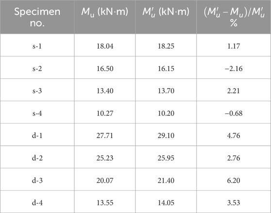
Table 2. Comparison of the calculated and tested bending bearing capacities.
According to Table 2, the relative error between the calculated and experimental values falls within a range of −2.16%–6.20%. The small discrepancies stem from three main factors: (1) Simplified assumptions in the calculation model, such as neglecting differential biting forces at the steel-concrete interface and assuming triangular stress distribution in concrete, which slightly underestimates compressive zone contributions. (2) Material property variability: Concrete tensile strength in tests varied from the design value, affecting dowel shear resistance. (3) Measurement errors in strain gauges and displacement sensors, contributing to minor deviations in ultimate load recording. Overall, the errors are within acceptable limits, validating the model’s reliability.
6 Conclusion and discussion
This study focused on the PCPJs of the first LSDW ship lock wall constructed in China. Scaled four-point bending tests were conducted to investigate the lateral bending performance and failure mechanisms of PCPJs across varying perforation ratios. Based on the observed failure mechanisms, a calculation method for determining the lateral bending bearing capacity of PCPJs was developed. The conclusions are as follows:
1. The lateral bending failure mode of the PCPJs manifested as follows: (a) The separation of the steel-concrete interface between the cross steel plate web and the flange (lower flange), with the separation interface forming an L shape rotated clockwise by 90°; (b) the concrete dowel between the holes of the cross steel plate flange (lower flange) broke, causing tensile cracks in the end concrete.
2. The load-displacement curve of the PCPJ under lateral bending moments can be divided into four distinct stages: elastic, elastoplastic, descending, and residual. The bending capacities of the single- and double-cross PCPJs (with a perforation ratio of 38.3%) in the elastic stage were 25.5% and 44.9% of the ultimate bearing capacity, respectively, whereas the bending capacities in the residual stage were 63.8% and 59.2% of the ultimate bearing capacity, respectively. Throughout all four stages, the steel plates and bars of the joints were in the elastic stage.
3. The lateral bending capacity of the double-cross PCPJ was greater than that of the single-cross PCPJ; however, both were lower than that of the non-joint segment. The ultimate bearing capacities of the single- and double-cross PCPJs, with a perforation ratio of 38.3%, were 13.8% and 22.9% of the ultimate capacity of the non-joint segment, respectively. For double-cross PCPJs with perforation ratios of 0%, 15.3%, 30.7%, and 38.4%, their lateral bending capacities were 1.30, 1.65, 1.68, and 1.66 times greater than those of single-cross PCPJs, respectively.
4. The lateral bending capacity of the PCPJs was positively correlated with the perforation ratio of the steel plate. Relative to PCPJ with a perforation ratio of 0%, single-cross PCPJ with perforation ratios of 15.3%, 30.7%, and 38.4% increased its bearing capacity by 25.9%, 55.6%, and 74.1%, respectively. In comparison, the bearing capacity of the double-cross PCPJ increased by 60.0%, 97.1%, and 122.9%, respectively.
5. The lateral bending capacity of PCPJs comprises the combined contributions of the web plate and the flange. Calculation formulas for the bending bearing capacity of each component were established. The deviation between the sum of the calculated values and the experimental results ranged from −2.16% to 6.20%.
Compared to conventional diaphragm walls, LSDWs have greater requirements for the transverse bearing capacity of their joints. The research findings of this paper provide a reliable design basis and an important reference for the practical application of PCPJs in LSDWs. The primary factors that influence the lateral bending capacity of PCPJs include the strength of the steel-concrete interface, the ratio of perforations, concrete shear strength, and the arrangement of the web. Modifying these factors can improve the lateral bending capacity of these joints. These results support the use of perforated cross-shaped steel plate joints in LSDWs, especially in situations where LSDWs primarily bear horizontal loads, such as in lock gate walls, dry dock walls, and foundation pit retaining structures.
Scaled model physical tests serve as an effective method for investigating the lateral bearing mechanism of perforated cross-plate joints (PCPJs); however, they exhibit significant limitations compared to actual engineering projects, primarily stemming from size effects that impact critical mechanical behaviors. These inherent size-dependent limitations manifest in three key aspects: (1) The bond strength at the steel-concrete interface displays size dependence, where smaller specimens tend to overestimate bond strength, potentially inflating the measured bearing capacity of the joints. (2) Concrete shear strength exhibits a decreasing trend with increasing specimen size, meaning that the 1:3 scale adopted in the tests may lead to an overestimation of dowel shear resistance when compared to full-scale prototypes. (3) Additionally, transverse axial forces which are present in full-scale LSDWs due to soil pressure were not simulated in the scaled tests, resulting in conservative measurements of structural stiffness. To address these size-related discrepancies and refine the analytical model, future full-scale tests and long-term field monitoring are necessary to account for these size-dependent effects comprehensively. Additionally, the tests did not account for the transverse axial forces acting on the joints, which may have resulted in overly conservative test outcomes. In the future, conducting full-scale model tests along with on-site measured data is expected to refine the research findings and enhance the reliability of the conclusions.
Data availability statement
The original contributions presented in the study are included in the article/supplementary material, further inquiries can be directed to the corresponding author.
Author contributions
KL: Writing – original draft. RY: Resources, Supervision, Validation, Writing – review and editing. WT: Data curation, Formal Analysis, Investigation, Writing – review and editing. QH: Methodology, Resources, Writing – review and editing. QK: Methodology, Supervision, Writing – original draft.
Funding
The author(s) declare that financial support was received for the research and/or publication of this article. The financial support from the Hubei Natural Science Foundation Youth Project (Grant No. 2024AFB409) and the National Natural Science Foundation of China (Grant No. 42462029) are acknowledged and appreciated.
Conflict of interest
Authors KL, RY, WT, and QK were employed by CCCC Second Harbor Engineering Company Ltd.
The remaining author declares that the research was conducted in the absence of any commercial or financial relationships that could be construed as a potential conflict of interest.
The handling editor TQ declared a past co-authorship with the author QH.
Generative AI statement
The author(s) declare that no Generative AI was used in the creation of this manuscript.
Any alternative text (alt text) provided alongside figures in this article has been generated by Frontiers with the support of artificial intelligence and reasonable efforts have been made to ensure accuracy, including review by the authors wherever possible. If you identify any issues, please contact us.
Publisher’s note
All claims expressed in this article are solely those of the authors and do not necessarily represent those of their affiliated organizations, or those of the publisher, the editors and the reviewers. Any product that may be evaluated in this article, or claim that may be made by its manufacturer, is not guaranteed or endorsed by the publisher.
References
Ahn, J., Lee, C., Won, J., and Kim, S. (2010). Shear resistance of the perfobond-rib shear connector depending on concrete strength and rib arrangement. J. Constr. Steel. Res. 66 (10), 1295–1307. doi:10.1016/j.jcsr.2010.04.008
Al-Darzi, S., Chen, R., and Liu, Y. (2007). Finite element simulation and parametric studies of perfobond rib connector. Am. J. Appl. Sci. 4 (3), 122–127. doi:10.3844/ajassp.2007.122.127
Chen, J., Wang, J., Qiao, P., Hou, Y., and Gu, Q. (2016a). Shear bearing of cross-plate joints between diaphragm wall panels – I: model tests and shear behaviour. Mag. Concr. Res. 68 (17), 902–915. doi:10.1680/jmacr.15.00325
Chen, J., Hou, Y., Wang, J., and Qiao, P. (2016b). Shear bearing of cross-plate joints between diaphragm wall panels – II: numerical analysis and prediction formula. Mag. Concr. Res. 68 (20), 1025–1039. doi:10.1680/jmacr.15.00326
Cheng, Q., Wu, J., Song, Z., and Wen, H. (2012). The behavior of a rectangular closed diaphragm wall when used as a bridge foundation. Front. Struct. Civ. Eng. 6, 398–420. doi:10.1007/s11709-012-0175-5
Fu, Z. (2022). “A case study on determining the optimal supporting structure scheme in deep excavation in river channels by 3D FEM analysis,” in 2022 8th international conference on hydraulic and civil engineering: deep space intelligent development and utilization forum (ICHCE) (Xi’an, China), 804–817. doi:10.1109/ICHCE57331.2022.10042635
GB50010 (2010). Code for design of concrete structures. Beijing, China: China Architecture and Building Press. (In Chinese).
Japan Association of Diaphragm Wall (2001). Outlook of underground continuous wall foundation, found (In Japanese). Eng. 29 (1), 60–65. Available online at: https://ndlsearch.ndl.go.jp/books/R000000004-I5625364 (Accessed January 01, 2001).
JGJ 120-2012 (2012). Technical specification for retaining and protection of building foundation excavations. Beijing, China: China Architecture and Building Press. (In Chinese).
Kim, S., Han, O., Kim, K., and Park, J. (2018). Experimental behavior of double-row Y-type perfobond rib shear connectors. J. Constr. Steel. Res. 150, 221–229. doi:10.1016/j.jcsr.2018.08.012
Lee, Y., Joo, Y., Lee, T., and Ha, D. (2011). Mechanical properties of constitutive parameters in steel–concrete interface. Eng. Struct. 33 (4), 1277–1290. doi:10.1016/j.engstruct.2011.01.005
Li, W., Tao, Q., Li, C., Wang, X., Gong, W., and Dai, G. (2024a). In-Situ experimental study of closed-diaphragm wall foundations for cross-sea suspension bridges. Mar. Sci. Eng. 12 (12), 2304. doi:10.3390/jmse12122304
Li, Z., Zhao, G., Zhang, Y., Hao, Z., Niu, K., and Liu, R. (2024b). Numerical modelling of sand liquefaction via a weakly coupled approach between lattice spring and discrete element methods. Comput. Geotech. 172, 106461. doi:10.1016/j.compgeo.2024.106461
Majdi, Y., Hsu, C., and Punurai, S. (2014). Local bond–slip behavior between cold-formed metal and concrete. Eng. Struct. 69, 271–284. doi:10.1016/j.engstruct.2014.03.025
Oguejiofor, E., and Hosain, M. (1994). A parametric study of perfobond rib shear connectors. Can. J. Civ. Eng. 21 (4), 614–625. doi:10.1139/l94-063
Soh, C., Chiew, S., and Dong, Y. (1999). Damage model for concrete-steel interface. J. Eng. Mech. 125 (8), 979–983. doi:10.1061/(ASCE)0733-9399(1999)125:8(979)
Song, J., Wang, W., Su, S., Ding, X., Luo, Q., and Quan, C. (2020). Experimental study on the bond-slip performance between concrete and a corrugated steel plate with studs. Eng. Struct. 224, 111195. doi:10.1016/j.engstruct.2020.111195
Trad, M., Bitar, I., Grange, S., and Richard, B. (2024). A multiscale steel–concrete interface model for structural applications. Structures 68, 107137. doi:10.1016/j.istruc.2024.107137
Wang, X., Liu, Y., Lu, Y., and Li, X. (2022). Shear transfer mechanism of perforated web connection for concrete encased steel structures. Eng. Struct. 252, 113418. doi:10.1016/j.engstruct.2021.113418
Wang, J., Xiong, W., and Cai, C. (2024). Flexural performance of rigid joints for diaphragm walls: experimental investigation and numerical analysis. Case Stud. Constr. Mater. 20, e02936. doi:10.1016/j.cscm.2024.e02936
Wu, J., Cheng, Q., Wen, H., Li, Y., Zhang, J., and Wang, L. (2016a). Comparison on the horizontal behaviors of lattice-shaped diaphragm wall and pile group under static and seismic loads. Shock Vib. 2016, 1–17. doi:10.1155/2016/1289375
Wu, J., Cheng, Q., Wen, H., Wang, L., Li, Y., and Zhang, J. (2016b). A load transfer approach to rectangular closed diaphragm walls. Geotech. Eng. 169 (6), 509–526. doi:10.1680/jgeen.15.00156
Wu, J., Naggar, M., Cheng, Q., Wen, H., Li, Y., and Zhang, J. (2020). Iterative load transfer procedure for settlement evaluation of lattice-shaped diaphragm walls in multilayered soil. Comput. Geotech. 120, 103409. doi:10.1016/j.compgeo.2019.103409
Xue, X., Hu, S., Qi, H., and Shan, C. (2022). Study on the normal bonding performance of the steel-concrete interface. Eng. Mech. 39 (5), 65–74. (In Chinese). doi:10.6052/j.issn.1000-4750.2021.03.0182
Yoshitake, I., Uno, T., Scanlon, A., and Hamada, S. (2011). Simplified test of cracking strength of concrete element subjected to pure shear. J. Mater. Civ. Eng. 23 (7), 999–1006. doi:10.1061/(ASCE)MT.1943-5533.0000259
Keywords: lattice-shaped diaphragm wall, perforated cross-plate joint, four-point bending test, bending bearing capacity, calculation method
Citation: Li K, Yang R, Tu W, Hu Q and Kong Q (2025) Lateral bending behavior and calculation of perforated cross-plate joints in lattice-shaped diaphragm walls. Front. Earth Sci. 13:1674671. doi: 10.3389/feart.2025.1674671
Received: 28 July 2025; Accepted: 28 August 2025;
Published: 17 September 2025.
Edited by:
Tongming Qu, Hong Kong University of Science and Technology, Hong Kong SAR, ChinaReviewed by:
Xin Han, Inner Mongolia University of Science and Technology, ChinaYi Yang, Dalian Jiaotong University, China
Copyright © 2025 Li, Yang, Tu, Hu and Kong. This is an open-access article distributed under the terms of the Creative Commons Attribution License (CC BY). The use, distribution or reproduction in other forums is permitted, provided the original author(s) and the copyright owner(s) are credited and that the original publication in this journal is cited, in accordance with accepted academic practice. No use, distribution or reproduction is permitted which does not comply with these terms.
*Correspondence: Rui Yang, eXJfc3dqdHVAb3V0bG9vay5jb20=