 Junghee Son1,2
 In Gul Hwang1,2*
- 1Department of Geological Science, University of Science and Technology, Daejeon, Republic of Korea
- 2Petroleum and Future Energy Research Center, Resource Exploration and Development Research Division, Korea Institute of Geoscience and Mineral Resources, Daejeon, Republic of Korea
This study presents a remarkably well-preserved funnel-shaped fluid-escape structure exposed within the Hakcheon–Chogok Megaturbidite of the Doumsan fan-delta, Southeast Korea. Detailed sedimentological observations indicate that the structure represents a clastic dyke complex formed through multiple, discrete fluidization events. These events are inferred to have been triggered by repeated instantaneous loadings associated with mass-transport processes at the base of steeply inclined (15°–30°) depositional slopes during fan-delta evolution. A key factor controlling the formation and evolution of the structure was the localized enrichment and infiltration of fine-grained sediments (<0.25 mm) in both the lower conglomeratic unit (pebble-rich conglomerate) and the overlying sand–mud unit (coarse sandstone to mudstone). This spatial variation facilitated selective infiltration between the two units, producing localized low-permeability barriers that promoted overpressure buildup and vertical fluid migration. Cross-cutting relationships and compositional contrasts among internal dyke-like structures define at least three distinct phases of fluidization: (Phase I) initial propagation of dendritic granule-rich dykes, stabilized by effective infiltration of fine-grained sediments; (Phase II) intrusion of fine sand-rich dykes accompanied by ductile deformation and conduit instability due to insufficient wall infiltration; and (Phase III) lateral migration of faint, medium sand-dominated pipes that crosscut earlier structures and generated massive sand bodies. Despite this lateral migration and instability, the left margin displays a sharp boundary and narrow fluidization halo, indicating localized infiltration along the dyke wall. The occurrence of fine-depleted pipes in the lower unit is interpreted to record partial fluidization and elutriation that redistributed fine particles along pre-existing pathways. This redistribution is interpreted to have reinforced previously fluidized zones and promoted subsequent fluidization at similar positions. These results demonstrate that the spatial distribution and dynamics of fine-grained sediments critically governed overpressure development, conduit morphology, and internal asymmetry of the funnel-shaped structure, providing new insights into sediment–fluid interactions and the formation of large-scale clastic intrusions within coarse-grained turbiditic systems.
1 Introduction
Fluid-escape structures are widespread in sedimentary rocks deposited in various depositional environments such as proximal parts of deep-sea fans, prodeltas, areas adjacent to channel (e.g., braided stream systems), aeolian sand seas, and glacial settings (Lowe, 1975; Allen, 1982; Postma, 1983; Netoff and Shroba, 2001; van der Meer et al., 2009; Hurst et al., 2011; Pisarska-Jamroży and Weckwerth, 2013; Ravier, 2024). These fluid-escape structures were traditionally attributed to consolidation-related processes such as: (1) seepage, in which increasing grain-to-grain stresses lead to the collapse of an unstable grain framework; (2) liquefaction, wherein particles are temporarily suspended in pore fluids and settle under the influence of fluid motion; and (3) fluidization, where particles are lifted and transported by upward movement of fluid flow (Lowe, 1975). In contrast, Allen (1982) emphasized that liquidization, which encompasses liquefaction and fluidization, plays a critical role in generating distinctive water-escape structures. More recent studies, however, have increasingly regarded fluidization as the primary process for generating various types of fluid-escape structures, including clastic dykes, sills, extrudites, and upward-widening structures such as conical-, funnel-, and saucer-shaped forms (Huuse et al., 2004; Chen et al., 2009; Hurst et al., 2011; Ross et al., 2011; Cartwright and Santamarina, 2015; Pisarska-Jamroży et al., 2019). Such structures are frequently identified in seismic data with kilometer-scale lateral extent and thickness of several seconds and have thus been interpreted as potential migration pathways or reservoirs for hydrocarbons (Dixon et al., 1995; Hurst et al., 2003; Hurst and Cartwright, 2007). Consequently, a number of studies have focused on understanding their formation processes (Hurst et al., 2011, and references therein).
Despite increasing interest in fluidization-related fluid-escape structures, the mechanisms responsible for the formation of funnel-shaped structures, characterized by upward-widening geometry, remain poorly understood. On seismic data, their formation was inferred from the rapid ascent of pore-fluid pressure associated with fracture networks or polygonal faults (Cartwright and Santamarina, 2015). Field data show that the funnel-shaped structures contain brecciated limestone fragments, similar to those of surrounding rock. These structures were interpreted as dykes formed by upward movement of fluidized sediment through a narrow conduit, which was gradually widened by the erosive capacity of the intruding fluidized sediments (Chen et al., 2009). On the other hand, Goździk and van Loon (2007) concluded that the upward-widening structures are related to downward-narrowing cracks filled with surface sediments. In sand-box experiments, however, the formation of funnel-shaped structures—typically surrounded by inward-dipping layers and massive at the center—was interpreted as the result of fluid expulsion exceeding lithostatic pressure (Nermoen et al., 2010). Although these previous studies provide important insights, the formation processes of upward-widening, funnel-shaped structures remain insufficiently constrained by field data.
In this study, we present a detailed analysis of an exceptionally well-preserved funnel-shaped structure exposed in a large-scale subaqueous gravity-flow deposit of the Doumsan fan-delta in the Pohang-Youngduk Basin, Southeast Korea. This structure provides a rare opportunity to examine how subtle variations in fine-grained sediment content and their redistribution during fluidization influenced fluid flow and sediment mobility. Recent carbonate–siliciclastic research (e.g., Yazdanpanah et al., 2025) has demonstrated that even subtle variations in microfacies and early diagenetic alteration can exert a significant control on pore-system evolution and fluid migration. Such insights provide a useful conceptual framework for evaluating how localized textural heterogeneity and fine-grained sediment infiltration may have influenced overpressure generation and conduit development within coarse-grained turbiditic settings like the Doumsan fan-delta. Based on detailed outcrop observations of internal sedimentary structures and grain-size distributions, the structure is interpreted to have formed through multiple, discrete fluidization events. In particular, we investigate how localized enrichment and infiltration of fine-grained sediments contributed to the development of overpressure, conduit morphology, and structural asymmetry during multiphase fluidization.
The main objectives of this study are threefold: (1) to describe in detail the internal architecture and composition of a well-preserved funnel-shaped fluid-escape structure exposed in the Doumsan fan-delta; (2) to reconstruct its multiphase formation history by integrating field-scale cross-cutting relationships with grain-size variations; and (3) to assess how the infiltration and redistribution of fine-grained sediments influenced overpressure buildup, conduit stability, and the final asymmetry of the structure. The novelty of this research lies in its integrated field-based approach that deciphers discrete fluidization events within a coarse-grained turbiditic system, emphasizing that dynamic permeability barriers formed by particle infiltration, rather than static lithological boundaries, controlled the evolution of large-scale clastic dykes.
2 Geological setting
The Miocene Pohang-Youngduk Basin, located in the southeastern part of the Korean Peninsula (Figure 1A), was formed by pull-apart style extension during the back-arc opening of the Ulleung Basin (Yoon and Chough, 1995). The basin was filled by non-marine to deep-marine sediments (more than 1 km thick), originating from six fan-delta systems along the western margin of the basin (Hwang et al., 1995). The Doumsan fan-delta, the largest among them, shows an entire spectrum of basin margin facies including alluvial fan, braided stream, submarine Gilbert-type top-, fore-, and toe-sets, prodelta, slope apron, and basin plain environments (Hwang et al., 1995). Extensive sedimentological mapping and analyses of 21 deep cores from the fan-delta revealed a four-stage evolutionary history controlled by tectonic subsidence and sediment supply (Hwang et al., 1995; Hwang et al., 2021; Figure 1B). During the initial stage (Stage 1), the fan-delta commences in a shallow marine environment. Subsequent syndepositional tectonic subsidence and high-rate of sediment supply resulted in the progradation of a high-gradient foreset (>30°), during Stage 2. In the Stage 3, the fan-delta experienced abrupt decrease in coarse-grained sediment supply, resulting in the thick accumulation of fine-grained sediments on steeply inclined foreset (15° ∼ 30°), base of slope, prodelta, and basin plain environments. As a result, frequent large-scale slope failures occurred (Chough et al., 1990). During the Stage 4, sediment supply from the alluvial feeder system ceased and the fan-delta was draped by thick hemipelagic mudstones.
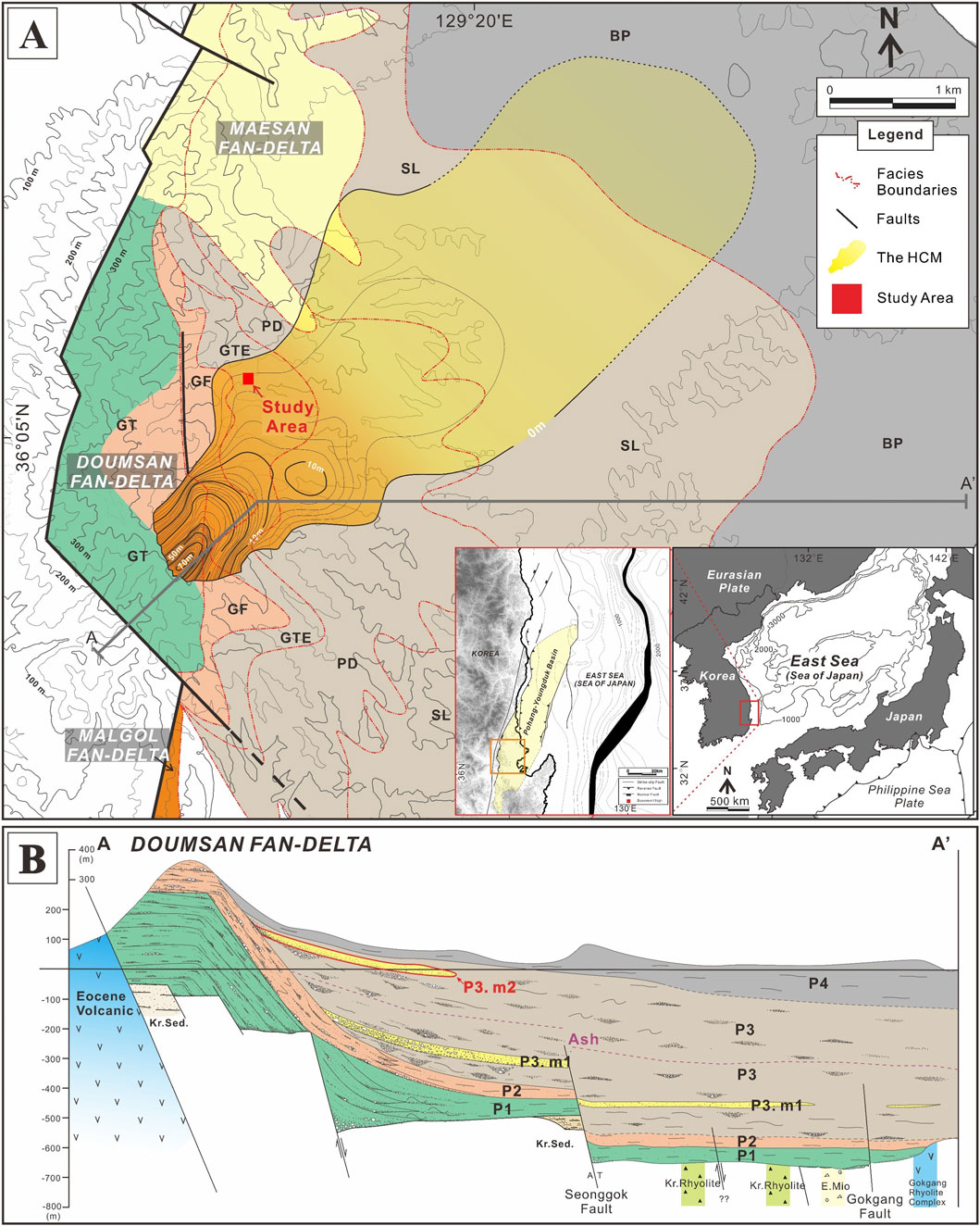
Figure 1. Geologic map of the Pohang-Youngduk Basin and adjacent areas (modified from Son et al., 2024). (A) Sedimentary facies map of the Doumsan fan-delta and adjacent area in the Pohang-Youngduk Basin. For location see the inset (Orange box). The location of the Pohang-Youngduk Basin is indicated in the inset (enlarged red box) (GT: Gilbert-type topset and alluvial fan, GF: Gilbert-type foreset, GTE: Gilbert-type toeset, PD: Prodelta, SL: Slope apron, and BP: Basin plain). Note the location of the study area at the boundary between the steeply inclined foreset (GF) and toeset (GTE). (B) Cross-section of the Pohang-Youngduk Basin. For location see (A). The cross-section shows the relationship between the steeply-inclined Doumsan fan-delta and the Hakcheon-Chogok Megaturbidite (P1: Stage P1 deposits, P2: Stage P2 deposits, P3: Stage P3 deposits and P4: Stage P4 deposits, Ash: Ash layer, P3.m1: the Pohang Megaturbidite, P3.m2: the Hakcheon-Chogok Megaturbidite).
The funnel-shaped structure occurs in a large-scale subaqueous gravity flow deposit, named the Hakcheon-Chogok Megaturbidite (HCM; Son et al., 2024), that was deposited during the Stage 3. This gravity flow deposit is exposed across the fan-delta from the foreset to the prodelta regions (Figure 1A). The HCM outcrop is over 70 m thick in the proximal part, and less than 4 m thick in the distal part, and laterally extends for about 6 km (Son et al., 2024; Figure 2). The megaturbidite is composed of three units; (1) matrix-supported cobble-to pebble-conglomerate, (2) clast-supported pebble-rich conglomerate, and (3) coarse sandstone to mudstone units in ascending order (Figure 2). The HCM was derived from a giant slope failure on the upslope part of the foreset and experienced various kinds of flow transformation, including cohesive debris flows, gravelly high-density turbidity currents as well as high- and low-density turbidity currents (Son et al., 2024).
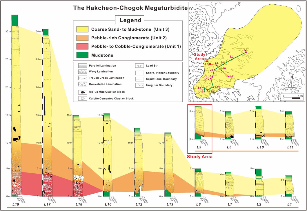
Figure 2. Schematic columnar logs of the HCM. Note downslope (green line) and lateral (orange line) variation in the pebble-to cobble-conglomerate (Unit 1), pebble-rich conglomerate (Unit 2), and coarse sandstone to mudstone (Unit 3) (modified from Son et al., 2024).
3 Methods
Sedimentological properties were carefully described along a valley of the Doumsan fan-delta, including bed thickness, grain size, depositional and erosional structures, post-depositional deformation structures, bed geometry, sorting, and clast shape. Correlation of individual depositional units was made by tracing each unit along the valley. To examine the relationship between the spatial distribution of fine-grained sediments and the localized occurrence of the funnel-shaped structure, grain-size analysis was conducted. A total of 19 samples were collected from the lower unit (the pebble-rich conglomerate; L1_LC, L2_LC, and L3_LC), the three divisions of the upper unit (the coarse sandstone to mudstone; L1_ML, L1_PLM, L1_PLFU, L2_ML, L2_PLM, L2_PLFU, L3_ML, L3_PLM, and L3_PLFU) (Figure 3A), three parts of the funnel-shaped structure (W1–W6), and the pillar-type structure (W7) (Figure 3B).
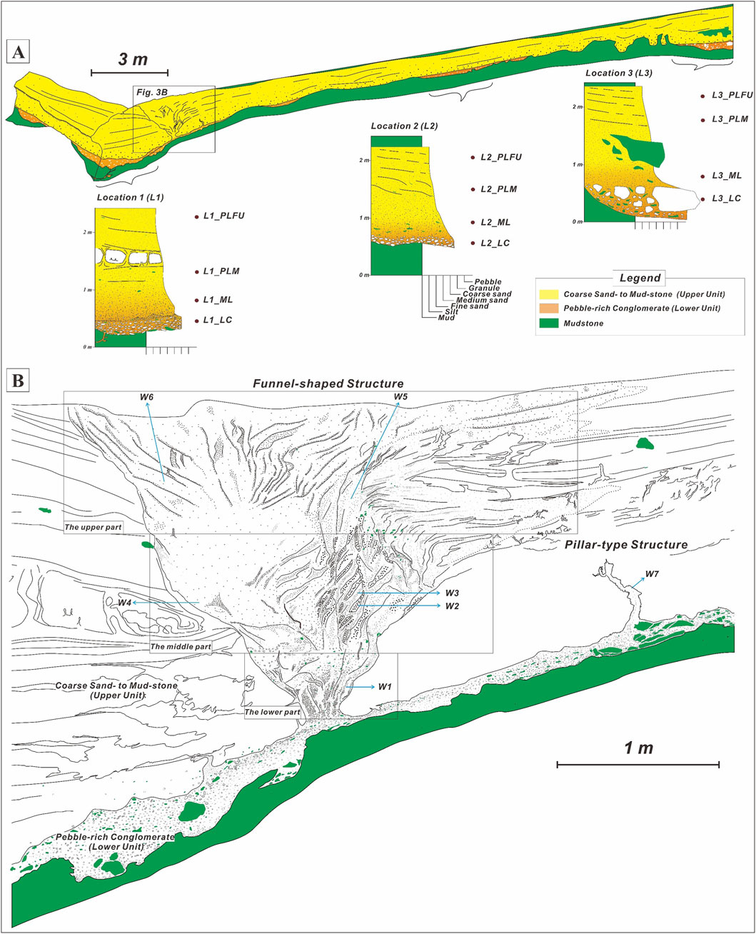
Figure 3. (A) Simplified sketch of outcrop and columnar logs, including the fluid-escape structures. Sample locations for grain size analysis was designated (see Table 1). (B) Detailed sketch of funnel-shaped fluid-escape structure. The funnel-shaped structure can be divided into three parts: lower, middle, and upper parts. Sample locations for grain size analysis was also designated (see Table 2).
Pretreatment was performed with hydrogen peroxide to remove organic matter and to reduce flocculation of the fine-grained sediments. Grain-size analyses were conducted using a combination of dry-sieving and pipette methods. Sand fractions (>0.063 mm) were separated using standard ASTM D422 procedures (ASTM International, 2007) at 1-phi intervals, whereas finer fractions (<0.063 mm) were analyzed by the pipette method following Syvitski (1991). In this study, grain-size fractions follow the Wentworth (1922) scale: gravel (64–2.0 mm), sand (2.0–0.063 mm), silt (0.063–0.004 mm), and clay (<0.004 mm). The cumulative-frequency curves were plotted on a phi scale, and statistical parameters, including mean grain size (Mz), sorting (σᵢ), skewness (Sk), and kurtosis (Kg), were calculated using the formulas of Folk and Ward (1957). Each sample was measured in triplicate, and deviations within ± 0.1 phi were accepted as analytical uncertainty. Grain-size data were processed and plotted using GRADISTAT v9.1 (Blott and Pye, 2001), which implements the Folk & Ward (1957) graphic method. Mean grain-size (Mz) values obtained with the software were identical to those calculated manually, confirming reproducibility. Standard-deviation (SD) values representing variability among samples were 0.155 mm for the Hakcheon–Chogok Megaturbidite (Table 1) and 0.031 mm for the fluid-escape structures (Table 2).
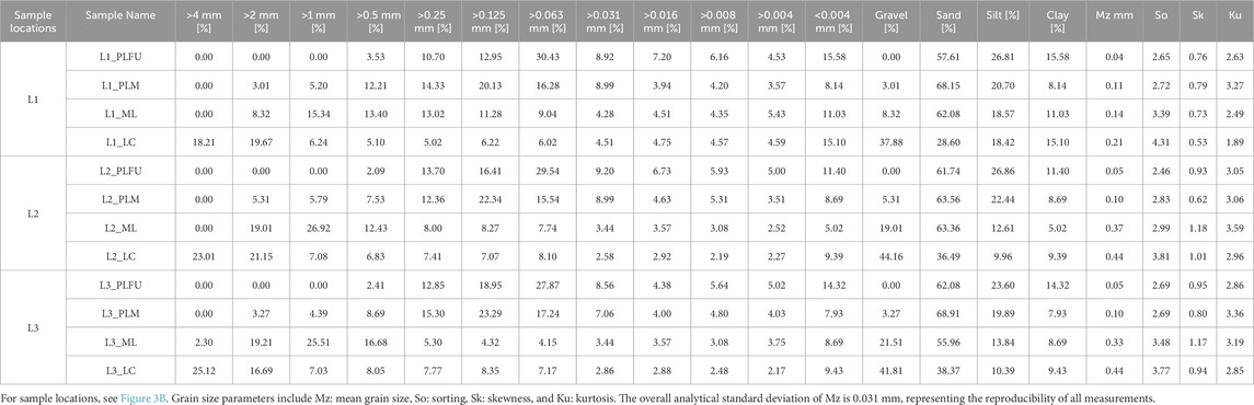
Table 1. Grain size distribution of the fluid-escape structures.
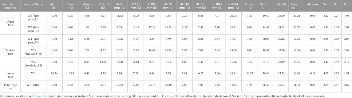
Table 2. Grain size distribution of the Hakcheon-Chogok Megaturbidite.
In addition, thin sections and scanning electron microscope (SEM) images were used to investigate the internal distribution and microfabric of fine-grained sediments in the fluid-escape structures. SEM imaging was conducted using a JEOL JSM-6610LV at the Korea Basic Science Institute (KBSI), Cheongju, Korea.
4 Results
4.1 Deposit characteristics
The measured outcrop section that includes the funnel-shaped structure occurs near the base of slope in the fan-delta, beyond the high-gradient foreset (Figure 1A). In this location, the outcrop section is encased in homogeneous mudstone and laterally extends about 50 m along a valley wall (Figure 3A). Notably, the funnel-shaped structure is laterally restricted to the left part of the outcrop, whereas the right part shows no evidence of fluidization-related deformation. Based on grain size, the measured outcrop deposits are divided into two units: a pebble-rich conglomerate and a coarse sandstone to mudstone unit, in ascending order (Figure 3A). These deposits were interpreted to have been deposited rapidly by a gravelly high-density turbidity current (Son et al., 2024).
The lower unit, the pebble-rich conglomerate, rests on homogeneous mudstone with sharp or truncated lower boundaries (Figure 4B). The conglomerate unit is generally several decimeters to 1 m thick (Figure 3A). This unit shows variable lateral continuity, either extending more than 10 m laterally along the scar surface or pinching out above the meter-scale scar surface. In the measured section, this unit shows more pronounced discontinuity with concave-up and -down lower and upper boundaries (Figure 3A). These conglomerates are composed of clast-supported pebble clasts with subordinate amount of cobble- and boulder-sized clasts (max. 1.2 m in long axis). The matrix consists of poorly-sorted granule to sand, but in some parts, particularly where the funnel-shaped structure occurs, the matrix changes into poorly-sorted sand, showing lateral variation in the proportion of fine-grained sediment. In the left part of the measured section, the unit directly underlies and connects to the funnel-shaped structure (Figure 4A). Fine-depleted, laterally or sub-vertically inclined pipe-like structures are also present (Figure 4C).
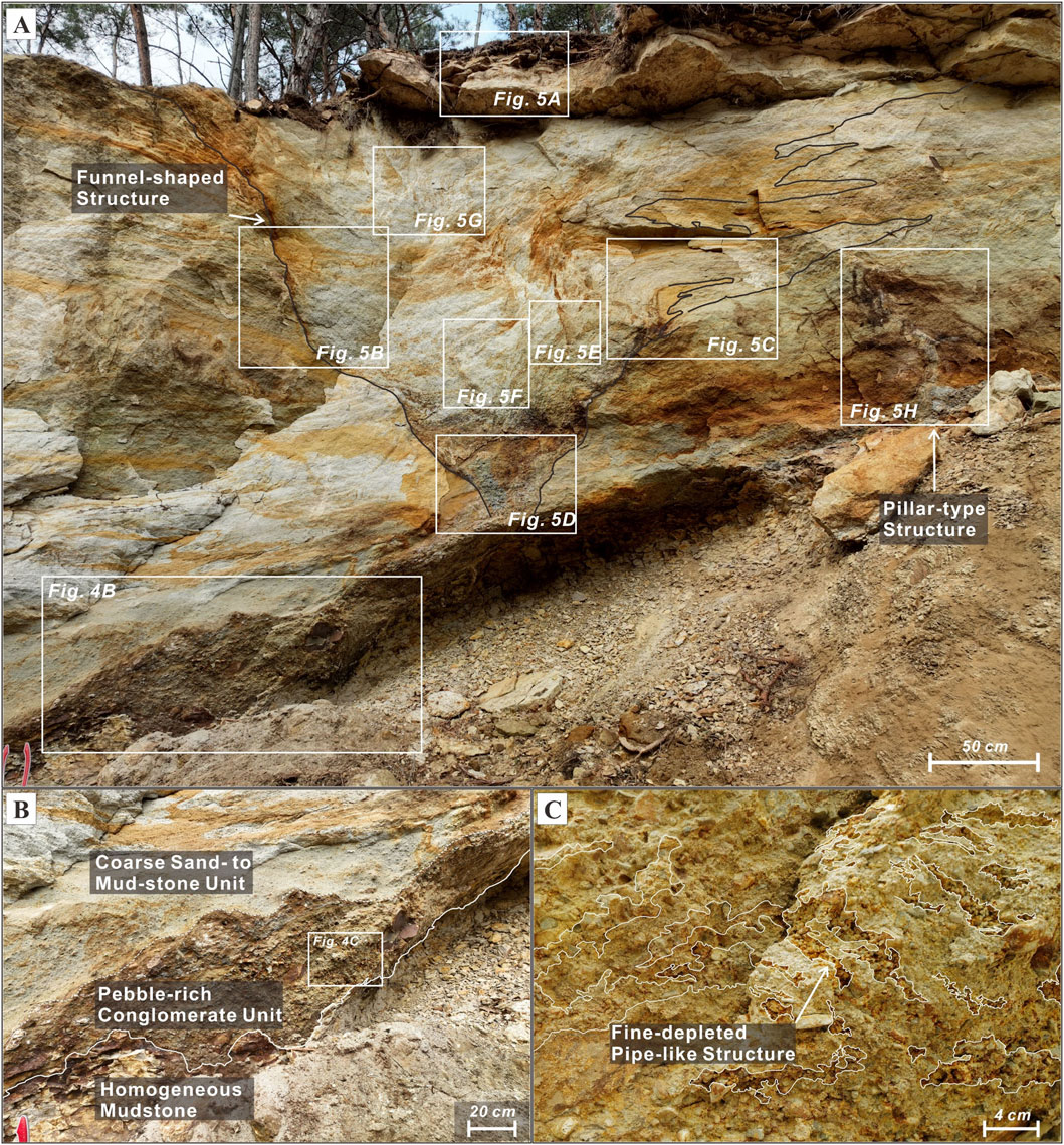
Figure 4. Photographs showing the fluid-escape structures and their relationship between the surrounding host and underlying parent rocks. (A) Overview of the fluid-escape structures in the measured section of the HCM. (B) The pebble-rich conglomerate unit beneath the fluid-escape structures and the coarse sandstone to mudstone unit surrounding these structures. For location, see (A). (C) The fine-depleted pipe-like structure occurring in the pebble-rich conglomerate. For location see (B).
The upper unit, the coarse sandstone to mudstone unit, overlies either the pebble-rich conglomerate with a transitional boundary or the homogeneous mudstone with sharp or erosional boundary (Figure 3A). The coarse sandstone to mudstone unit is laterally continuous. This unit ranges in thickness from 1 m to 4 m and is thickest on the left part of measured section where the fluid-escape structures occur (Figure 3A). This unit generally consists of massive coarse sand division (Bouma divisions: Ta) at the base, laminated medium sand division (Tb) in the middle, and laminated fine sand division (Td) at the top (Figure 3A). Locally, soft-sediment deformation features such as convoluted layers (Tc) are observed within this unit (Figure 3A). In the left part of the outcrop, this unit surrounds the funnel-shaped structure (Figure 4A), and in some areas, it is overlain by homogeneous mudstones (Te) (Figure 3A).
4.2 Spatial variation of the fine-grained sediments
Grain-size analysis was conducted to explore variations in sediment composition across the measured section. This section presents the spatial trends in fine-grained sediment content, particularly focusing on the lateral differences between the left and right parts of the outcrop. In the lower unit (L1_LC, L2_LC, and L3_LC, for location of samples, see Figure 3A), the mean grain size of the matrix ranges from 0.21 mm to 0.44 mm. The particles of the lower unit are divided into four grain size components, gravel, sand, silt, and clay, with relative percentages ranging from 38%–44%, 29%–38%, 9%–18% and 9%–15%, respectively (Table 1). In the left part, where the fluid-escape structures occur, the mean grain size of the matrix within the lower unit decreases to 0.21 mm, accompanied by an increase in ≤ silt-sized grains to ∼34% (Table 1).
As mentioned above, the upper unit consists of three divisions: the massive coarse sand, the laminated medium sand, and the laminated fine sand divisions, in ascending order. The massive sediment divisions (L1_ML, L2_ML, and L3_ML) are composed of gravel, sand, silt, and clay, with relative percentages ranging from 8%–22%, 56%–63%, 13%–19%, and 5%–11%, respectively (Table 1). Their mean grain sizes range from 0.14 mm to 0.37 mm. In the left part, the mean grain size decreases to 0.14 mm as the content of < medium sand fraction (<0.25 mm) drastically increases to ∼50%. Also, the laminated medium sand divisions (L1_PLM, L2_PLM, and L3_PLM) in the middle part consist of gravel (3%–5%), sand (64%–69%), silt (20%–22%), and clay (8%–9%). Although the mean grain size in the left part increases slightly from 0.10 mm to 0.11 mm, the variation is negligible compared to that of underlying massive division (Table 1). In the upper part, the laminated fine sand divisions (L1_PLFU, L2_PLFU, and L3_PLFU) are composed of three components: sand (58%–62%), silt (24%–27%), and clay (11%–16%). Their mean grain sizes range from 0.04 mm to 0.05 mm corresponding to coarse silt (Table 1).
These results reveal a pronounced lateral enrichment of fine-grained sediments, particularly silt and clay, toward the left part of the measured section, where the fluid-escape structures are concentrated. This spatial trend suggests that the formation and localization of the fluid-escape structures are closely linked to variations in fine-grained sediment content, which likely influenced the permeability and rheological behavior of the conglomerate and the overlying sand–mud succession.
4.3 The fluid-escape structures
Meter-scale fluid-escape structures are exclusively observed in the left part of measured outcrop section (Figure 3A). The meter-scale fluid-escape structures intrude the overlying coarse sandstone to mudstone unit and clearly intersect the primary sedimentary structures. Based on their morphology, the fluid-escape structures are divided into two distinct types; the funnel-shaped and the pillar-type structures (Figure 3B).
4.3.1 The funnel-shaped structure
The funnel-shaped structure has a height of 2.3 m. The width is 0.4 m at the base, increasing to 2.4 m at the top (Figure 3B). The base of the funnel-shaped structure occurs just above the inner facies boundary between the pebble-rich conglomerate and the coarse sandstone to mudstone (Figure 4A). The top of the funnel-shaped structure is mostly eroded; however, in some parts, it is overlain by silty layer with deformed boundary (Figure 5A). The funnel-shaped structure is bounded by sub-vertical margins that discordantly intersect primary sedimentary structures of the surrounding sediments with different geometries on the left and right margins (Figure 3B). The left margin is sub-vertical with inclination of approximately 45° from the base to the top and displays a sharp truncated geometry with smooth and jagged shapes (Figure 5B). Outer parts of the left margin are partly surrounded by deformed sand deposits with a maximum width of 0.02 m, showing small-scale flame structures (Figure 5B). The right margin is also sub-vertically inclined with a truncated geometry from the base to 1.1 m high. Outer part of the right margin is represented by deformed massive sandstone (max. width: 0.08 m; Figure 5C). The right margin vertically changes into sub-vertically curved laminae or softly deformed sediment folds (Figure 5C).
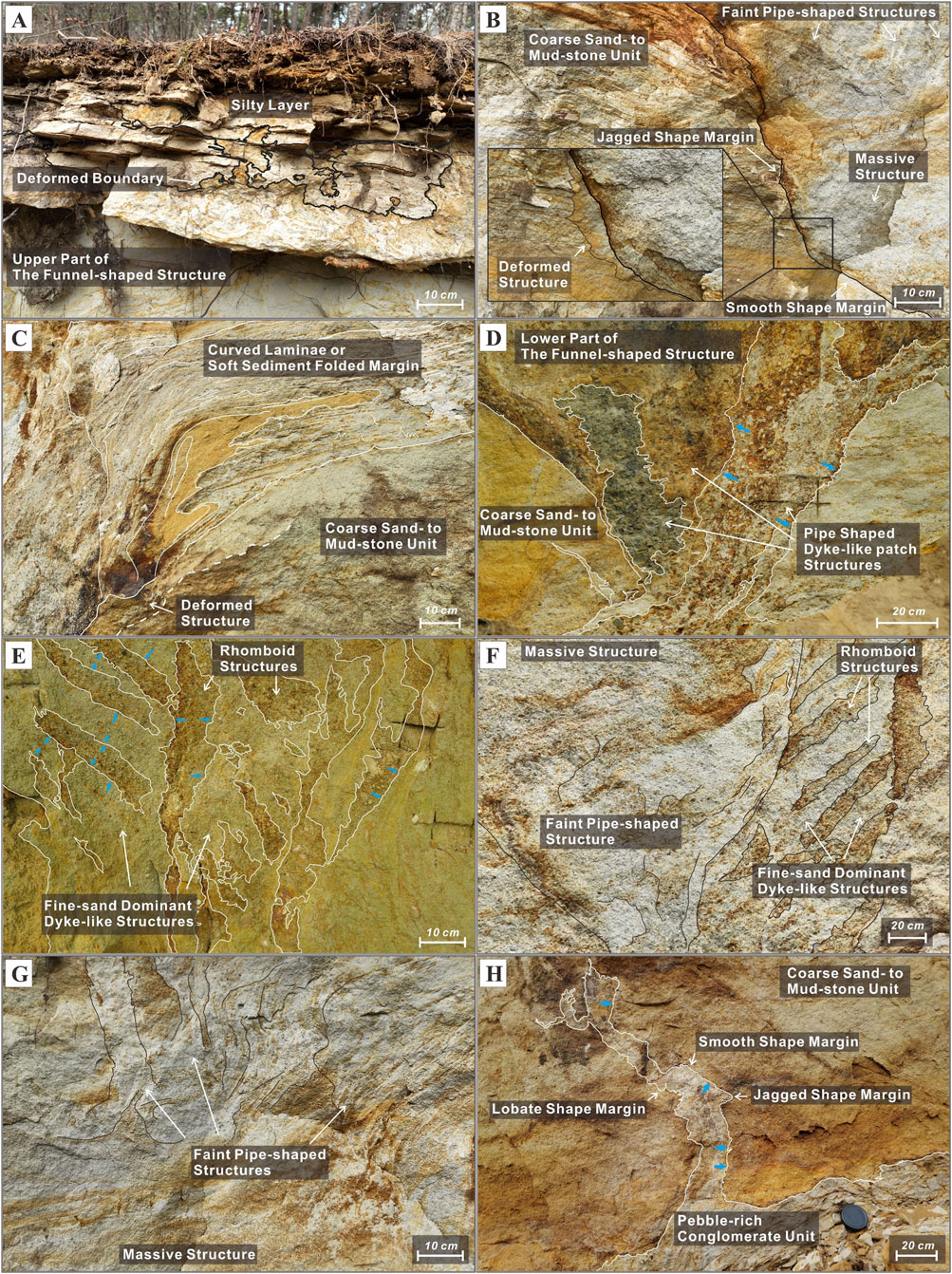
Figure 5. Photographs illustrating the internal structures and geometries of the funnel-shaped structure in (A–G) and the pillar-type structure in (H). For locations, see Figure 4A. (A) The upper part of the funnel-shaped structure overlying silty layer with deformed boundary. (B) The left margin of the funnel-shaped structure showing sharp truncated geometries with smooth and jagged shapes. Deformed sand deposits with small flame structures occur locally along the outer margin. (C) The right margin of the funnel-shaped structure showing a combination of truncated and softly deformed geometries. (D) The lower part of the funnel-shaped structure containing three distinct, vertically-oriented, pipe-shaped dyke-like patch structures intruding into the overlying unit. Blue arrows indicate the direction of lateral grading. (E) The middle part of the funnel-shaped structure showing cross-cutting relationships between granule-dominated rhomboid structures and fine-sand-dominated dendritic or pipe-shaped structures. Both structures display lateral grading (blue arrows). (F) The faint pipe-shaped structure intersecting both rhomboid and dendritic dyke-like structures in the middle part of the funnel-shaped structure. (G) The faint pipe-shaped structures in the upper part of the funnel-shaped structure, showing the cross-cutting relationship between them. Some structures show massive internal textures. (H) The pillar-type structure, which trifurcates into three segments near the top. The margin displays a combination of brittle deformation (smooth and jagged shapes) and ductile deformation (lobate shape). Lateral grading is observed in some segments (blue arrows).
The funnel-shaped structure is filled with pebble-to clay-sized sediments which are similar in grain size and composition to the clasts or matrix of the pebble-rich conglomerate just below the funnel-shaped structure. A notable internal feature is the presence of vertically or sub-vertically oriented dyke-like patch structures, which are usually bounded by sharp contacts with prominent difference in grain size. These dyke-like patch structures commonly show cross-cutting relationships (Figure 3B). Based on the size, shape, and composition of the dyke-like patch structures, the funnel-shaped structure can be subdivided into three parts: the lower, middle, and upper parts.
The lower part of the funnel-shaped structure gradually widens from 0.4 m at the base to 0.9 m at the top (Figure 3B). This part is composed of more than three dyke-like patch structures (Figure 4D). The width of the individual dyke-like patch structures ranges from 0.05 m to 0.15 m with height ranging from 0.1 m to 0.3 m. The dyke-like patch structures are represented by vertically or sub-vertically inclined pipe shape (Figure 5D). Prominent cross-cutting relationships are observed among them (Figure 5D). Each dyke-like patch structure contains more than 20 wt% gravel (
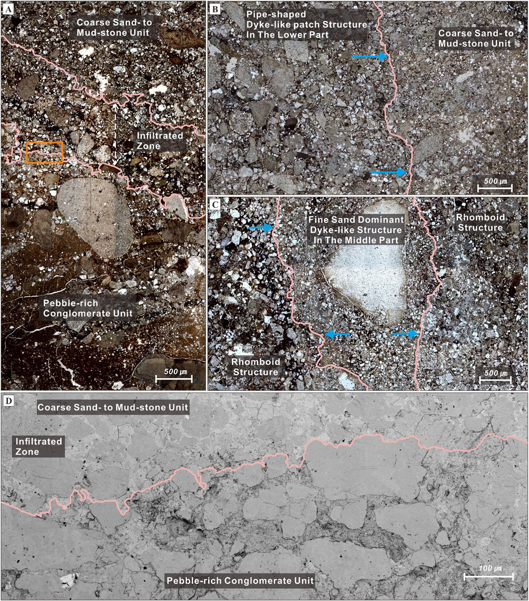
Figure 6. Photomicrographs (A–C) and Scanning Electron Microscope image [SEM; (D)] of boundaries between the parent and host rocks, and internal dyke-like patch structures. (A) The boundary between the pebble-rich conglomerate (the parent rock) and the coarse sandstone to mudstone (the host rock), showing fine-grained sediment accumulations in infiltrated zone. (B) The pipe-shaped dyke-like patch structures in the lower part of the funnel-shaped structure, intersecting the host rock (the coarse sandstone to mudstone unit). The pipe-shaped structure shows lateral grading pattern (blue arrows). (C) The cross-cutting relationship between the rhomboid dyke-like structures and the pipe- or dendritic-shaped structures in the middle part of the funnel-shaped structure. Note lateral grading in the pipe fill (blue arrows). (D) SEM image of the boundary between the pebble-rich conglomerate and the coarse sandstone to mudstone. For location see (C).
The width of the middle part increases from 0.9 m at the base to 2 m at the top (Figure 3B). This part contains more than 20 dyke-like patch structures. Most dyke-like patch structures have a width of approximately 0.1 m; some larger structures with a maximum width of 0.3 m also occur. The height ranges from 0.05 m to 0.5 m. They show rhomboid, vertically inclined pipe, or dendritic shapes on the right side (Figure 5E). In contrast, faint pipe-shaped structures dominate the left side (Figure 5F). On the right, the rhomboid-shaped structures are mainly composed of coarse-grained sediments ranging from coarse to medium sand with less than 5 wt% gravel (
In the upper part of the funnel-shaped structure, the width increases from 2 m at the base to 2.9 m at the top (Figure 3B). This part contains more than 40 dyke-like patch structures, which have an average width of approximately 0.02–0.03 m (max. 0.4 m) with heights ranging from 0.02 m to 0.3 m. On the left side of this part, these structures are represented by vertically or sub-vertically inclined faint pipe shapes (Figure 5G). On the right side, however, vertically inclined pipe- and curved string shapes are predominant (Figure 3B). On the left, the faint pipe-shaped structures are composed mainly of medium to fine sand (ca. 30 wt%), with ca. 20 wt% clay (Table 2). Most faint pipe-shaped structures are not connected to the faint pipes of the middle part (Figure 5G). In contrast, the vertical pipe and curved string-shaped structures are connected to the fine sand-dominant pipe- or dendritic-shaped structures of the middle part (Figure 3B). They show similar compositions to the pipe- or dendritic-shaped structures of the middle part (Table 2).
4.3.2 Interpretation
The discordant cross-cutting relationships between the funnel-shaped structure and the primary sedimentary structures of the overlying coarse sandstone to mudstone unit indicate that the funnel-shaped structure was formed after the deposition of the Hakcheon-Chogok Megaturdibite (Figure 4A). The compositional similarity between the infill of the funnel-shaped structure and the clast and matrix of the underlying pebble-rich conglomerate suggests that the source sediments originated from the underlying conglomerate. Thus, the pebble-rich conglomerate is interpreted as the parent rock, supplying remobilized sediments into the funnel-shaped structure, whereas the coarse sandstone to mudstone unit is considered the host rock (cf. Hurst et al., 2011). The presence of fine-depleted pipe-like structures in the parent rock implies elutriation of fine particles, which is characteristic of partial fluidization (Lowe, 1975) (Figure 4C). Therefore, the funnel-shaped structure is interpreted to have formed by upward migration of a fluid-sediment mixture (Lowe, 1975; Hurst et al., 2011), rather than by downward sediment infill into tectonically generated fissures (cf. Goździk and van Loon, 2007).
The margins of the funnel-shaped structure vary with deformation style, exhibiting truncated geometries; smooth and jagged shapes (Figure 5B), and soft sediment deformed geometries; curved laminae or softly deformed fold shapes (Figure 5C). The truncated geometries may have formed by brittle deformation of the host rocks, whereas the soft sediment deformed geometries likely reflect a ductile deformation style (c.f. Dodd et al., 2020). These contrasting deformation styles in the margins of fluid-escape structure were attributed to variations in the rheological properties of the host material surrounding the fluid-escape structure. Proposed controlling factors include: (1) lithological heterogeneity of the host material, such as impermeable mudstones interbedded with thin sandstones (Hurst et al., 2011); (2) lithification by compaction over time (Dodd et al., 2020); and (3) infiltration of fine-grained sediments that plug pore spaces and alters sediment behavior (Lowe, 1975; Mount, 1993; Ross et al., 2011). In the case of the funnel-shaped structure, the host rocks surrounding the funnel-shaped structure comprise sand deposits that originated from a single giant turbidite. The lithological heterogeneity is inadequate for the explanation for the contrasting deformation styles in the margins of funnel-shaped structure. Also, the deformed sand deposits that appear as massive or flame-like features, surrounding parts of both margins, are interpreted as halo structures, a term used by Mount (1993), and are thought to have formed by the lateral infiltration of fluids and fine-grained sediments radiating outward from the central fluidized conduit. These halos suggest that the host sediment was sufficiently soft to permit such infiltration during fluidization. Therefore, we infer that fine-grained sediment infiltration, by altering the rheological behavior of the host sediment, was the primary controlling factor in producing the contrasting deformation styles along the margins of the funnel-shaped structure, rather than lithification or sediment heterogeneity.
The cross-cutting relationships between the internal dyke-like patch structures within the funnel-shaped structure indicate that the funnel-shaped structure underwent multiple fluidization events (Peterson, 1968; Hurst et al., 2003; van der Meer et al., 2009; Phillips et al., 2013). The presence of three dyke-like patch structures in the lower part of the funnel-shaped structure suggests that the fluidization events occurred at least three times (Figure 5D). Furthermore, based on the cross-cutting relationship and compositional differences between the internal dyke-like patch structures of the middle part, the dyke-like structures can be divided into three groups: (1) Rhomboid-shaped structures, dominated by granule, (2) Dendritic/pipe-shaped structures, composed of fine sand, and (3) Faint pipe-shaped structures, composed of medium sand. This succession of intrusive features is interpreted as the result of three distinct phases of clastic dyke intrusion, reflecting episodic fluidization events that progressively overprinted earlier structures. These well-preserved dyke-like structures often exhibit lateral grading patterns (Figures 5D,E) consistent with experimental studies on fluidization pipes lined with fine-grained sediments (Mount, 1993; Ross et al., 2011). The lateral grading is closely associated with the infiltration of fine-grained sediments into the dyke walls. These infiltrations likely played a role in stabilizing the dyke geometries, preventing their lateral migration and thereby inhibiting the development of massive sand bodies (cf. Ross et al., 2011).
4.3.3 The pillar-type structure
The pillar-type structure is approximately 1 m high, with width ranging from 0.05 m to 0.1 m. This structure is surrounded by the coarse sandstone to mudstone unit and is directly connected to the underlying pebble-rich conglomerate (Figure 5H). The pillar-type structure cuts discordantly through the primary sedimentary structures of the coarse sandstone to mudstone units. The pillar-type structure is curved, but it trifurcates into three distinct pipes near the upper part of the structure (Figures 3B, 5H). The curved margins show various deformation styles such as smooth, jagged, or lobate shapes (cf. Dodd et al., 2020) (Figure 5H).
The pillar-type structure is filled with fine to very fine sand (ca. 40 wt%), silt (ca. 30 wt%), with a small amount of clay (ca. 11 wt%, Table 2). A negligible amount of gravel (ca. 1 wt%) and rip-up mud clasts also occur in the lower boundary between the pillar-type structures and the underlying pebble-rich conglomerate (Figure 5H). The internal structure is predominantly massive. However, in some intervals, especially where the margins of pillar-type structure are smooth or jagged, showing a lateral grain-size grading is observed, transitioning from coarse sand at the center to silt at the margin. In contrast, the margins with lobate shapes generally lack a clearly developed lateral grading pattern (Figure 5H).
4.3.4 Interpretation
The cross-cutting relationship between the pillar-type structure and the primary sedimentary structure of the host rock indicates that this structure was formed after the deposition of the HCM. Direct connection between the pillar-type structure and the underlying pebble-rich conglomerate indicates that the conglomerate acted as a parent rock supplying materials into the structure. The curved margins of the pillar-type structure may represent examples of ptygmatic folding associated with post-fluidization compaction of soft host successions (Kane, 2010; Hurst et al., 2011). The right margin shows truncated deformation types (smooth and jagged shapes) with a brittle deformation style. On the other hand, the left margin shows soft deformation type (lobate shapes) with a ductile deformation style (c.f. Dodd et al., 2020). As mentioned above, the contrasting deformation styles in the margins of fluid-escape structure are interpreted as the effect of infiltration of the fine-grained sediments, by which the rheological properties of the right margin are likely to change into more impermeable than those of the left margin. In this study, the effect is also evidenced by lateral grading patterns that are identified at the brittlely deformed margin (Figure 5H).
The infill of the pillar-type structure consists of mud to granule (Table 2). The sediments are similar to the matrix and clasts of the parent rock, but have more clay to silt grade sediments than that of the matrix of the parent rock (Table 2). The variation in sediment compositions is likely related to the elutriation of fine particles during the upward movement of fluidized material (Lowe, 1975; Hurst et al., 2011). Within a closed system, where the clastic dyke was not connected to the paleo-seafloor, the upwelling fluid-sediment mixture created space for vertical propagation. When pore pressure dropped below the confining stress, the propagation ceased, leading to the accumulation of fine particles within the dyke (Dodd et al., 2020). Coarse particles, which are less likely to be elutriated, were likely to be trapped in the proximal part. The abrupt grain freezing likely contributed to the massive internal structure observed in the pillar-type structure (Jonk, 2010). The trifurcation observed in the upper part of the structure is interpreted to represent an early-stage fluidized conduit that split into three paths during propagation, possibly due to localized variations in sediment strength or pore pressure. Overall, the pillar-type structure is interpreted to have formed by a single, relatively short-lived fluidization event compared to the funnel-shaped structure.
5 Discussions
5.1 The influences of spatial variation in fine-grained sediments on the formation of the funnel-shaped structure
The localized occurrence of fluid-escape structures in the left part of the measured section coincides with the spatial enrichment of fine-grained sediments within both the parent and host rocks. Nichols et al. (1994) experimentally demonstrated that even in the absence of a pre-existing impermeable layer between the parent and host rocks, fine-grained sediments from the underlying parent rocks can ascend and infiltrate the overlying host rocks by passing through their pore space. This infiltration process itself may generate a localized impermeable barrier, effectively trapping fluids and promoting conditions that facilitate fluidization. This infiltration process is most effective when the grain size of the parent sediments is less than approximately 15% of the diameter of the host sediment grains. Conversely, when the parent grains are smaller than 8% of the host grain size, they can freely migrate through the host’s pore network (Nichols et al., 1994). In our observations, the mean grain size of the massive coarse sand unit in the host rock decreases sharply from 0.33 mm on the right part of the measured section to 0.14 mm on the left part, accompanied by an increase in the proportion of fine-grained sediments (<0.25 mm), including fine sand, silt, and clay (Table 1). Under these conditions, the ideal grain size for infiltration from the parent rock ranges from medium to fine silt (approximately 0.021 mm–0.011 mm). This range matches our grain-size analysis near the funnel-shaped structure, where the weight fractions of medium to fine silt-sized grains are nearly twice as high as in other locations (Table 2). Furthermore, the presence of a fine-grained sediment-enriched zone within the interparticle spaces of the massive coarse sand division in the host rock, immediately overlying the parent rock (Figures 6A,D), provides evidence for substantial infiltration of fine-grained sediments into the host rock. These observations support the interpretation that infiltration of fine-grained sediments into the host rock led to the formation of a localized, impermeable barrier. This barrier likely contributed to the development of an overpressure zone beneath it, facilitating the formation of the funnel-shaped fluid-escape structure.
The infiltration of fine-grained sediments can also occur during episodes of fluidization within clastic dykes (Lowe, 1975; Mount, 1993; Mörz et al., 2007; Ross et al., 2011). Experimental study by Ross et al. (2011) demonstrated that such infiltration into the dyke wall plays a critical role in controlling the stability of clastic dykes, as indicated by the formation of fine-grained linings along dyke walls. This observation supports our interpretation that sufficient infiltration of fine-grained sediments during fluidization contributed to the stability and preservation of clastic dykes (Figures 5D,E, 6B,C). A similar phenomenon was described by Mount (1993), who reported fine-grained sediment linings, referred to as fluidization haloes, around the outer margins of central pipes. The extent of these haloes depends on infiltration of fine-grained sediments into the pipe wall, which can reduce lateral permeability. A relatively thin halo may therefore indicate more effective infiltration of fine-grained sediments into the pipe’s wall. This interpretation is consistent with our observation that the deformed sand structure along the left margin of the funnel-shaped structure, where brittle deformation is observed, is thinner (0.02 m; Figure 5B) than the deformed structure on the right margin (0.08 m; Figure 5C), which displays a brittle-to-ductile deformation. Sufficient infiltration of fine-grained sediments into the clastic dyke wall on the left margin during fluidization is interpreted to have restricted lateral fluid leakage and maintained upward fluid pressure, thereby promoting more efficient vertical fluid migration. In contrast, insufficient infiltration of fine-grained sediments into the right margin may have allowed more frequent fluid leakage, leading to deformation styles more typical of ductile response.
Furthermore, previous studies have shown that during fluidization, fine-grained sediments not only infiltrate into host deposits or dyke walls, but also undergo significant mobilization within the parent rock itself, accompanied by elutriation of fine particles such as clays, silts, and fine-grained quartz and feldspar (Lowe, 1975). Such elutriation, referred to as the partial fluidization, may cause redistribution of the fine-grained sediments through the elutriation pipes (Lowe, 1975). These pipes exhibit sedimentological fabrics that have been cleared of fine particles, while the overall grain framework remains intact (Lowe, 1975; Roche et al., 2001; Hurst et al., 2011). Such characteristics are analogous to those observed in the fine-depleted pipes, which frequently occur in the parent rock (Figure 4C). Therefore, the presence of fine-depleted pipes in the parent sediments suggests that redistribution of fine-grained particles by elutriation has taken place. Based on experimental study of grain-displacive gas migration through fine-grained sediments, Sun and Santamarina (2019) observed that repeated fluid injections tend to follow similar pathways. This suggests that elutriated fine-grained sediments may also migrate along these routes, supplying previously fluidized zones and promoting subsequent fluidization through re-infiltration into the host sediments. In particular, the localized enrichment of elutriated clay particles may have enhanced the cohesiveness of the infiltrated layer, potentially inhibiting its break-up and promoting overpressurization within the parent sediment. The cohesiveness of the infiltrated layer is influenced by its clay content. Nichols et al. (1994) suggested cohesion begins to inhibit erosion and break-up when the clay content exceeds 15 wt%. Similarly, Lupini et al. (1981) reported that significant effects on soil strength appear when clay content reaches around 20 wt%. In our study, the clay content of the parent rock near the funnel-shaped structure is 15.1 wt% (Table 1). The content of clay is also likely to have increased due to the influx of easily elutriated clays (Lowe, 1975; Roche et al., 2001). The clay’s cohesiveness is considered to have influenced the initial stage of fluidization, while subsequent behavior was likely governed by the concentration of elutriated clays.
In summary, localized enrichment of fine-grained sediments likely promoted selective infiltration into overlying host sediments, forming discrete, low-permeability barriers. These barriers are interpreted to have enhanced the development of overpressure zones and contributed to the preservation of fluid-escape structures such as clastic dykes. Moreover, elutriated fine-grained materials from the parent rock may have been redistributed along or near previously fluidized pathways, forming additional impermeable layers in those zones. In particular, the accumulation of clay-rich material may have increased the cohesiveness of the infiltrated zone, which would have suppressed fluid escape and facilitated the development of localized overpressure.
Recent experimental and field studies (Pisarska-Jamroży and Weckwerth, 2013; Pisarska-Jamroży et al., 2019; Ravier, 2024) have further demonstrated that small-scale variations in grain size, sorting, and the associated cohesion and permeability exert a fundamental control on the localization and geometry of water- and fluid-escape structures. These studies show that subtle textural heterogeneities and fine-grained barriers can confine overpressure and promote discrete fluidization events, a mechanism consistent with the multiphase development and margin asymmetry observed in this study.
Although the formation of localized low-permeability zones in this study is primarily attributed to fine-grained infiltration, similar processes of porosity reduction can also occur through early diagenetic reactions. Varkouhi et al. (2020), Varkouhi et al. (2024) showed that silica diagenesis and associated pore-water chemistry shifts can enhance sealing efficiency by promoting precipitation of opal-CT and clay minerals within pore spaces. Such diagenetic modification, superimposed on mechanically infiltrated layers, could further stabilize semi-impermeable barriers and contribute to the persistence of overpressure conditions during successive fluidization episodes.
5.2 Possible triggering events
Previous studies have suggested that the multiple fluidization events may be triggered by earthquake-related seismicity (Obermeier, 1996; Bonini, 2019), rapid migration of fluid (Massari et al., 2001; Wattrus et al., 2003; Davies et al., 2006; Dodd et al., 2020), or instantaneous loading (Postma, 1983; Jonk et al., 2007; Jonk, 2010; van der Meer et al., 2009; Hurst et al., 2011; Phillips et al., 2013). Earthquakes exert direct shear stress on unconsolidated sediments, significantly increasing pore fluid pressure within the unconsolidated sediments (Obermeier, 1996; Bonini, 2019). Such seismic shaking can induce extensive soft-sediment deformation, including clastic dyke formation, up to 15–20 km from the epicenter. The spatial distribution of clastic dykes in seismically active areas is thus considered a key indicator of seismic triggering (Obermeier, 1996). This criterion is consistent with the spatial distribution of the liquefaction-induced structures that occurred by the 2017 Pohang Earthquake (Gihm et al., 2018) in this study area. However, it is inadequate to explain the distribution of the funnel-shaped structure because the funnel-shaped structure occurs limitedly at the base of slope.
Another possible mechanism is the rapid migration of fluids into unconsolidated sediments beneath impermeable layers. Such rapid fluid movement under shallow burial conditions can be driven by processes such as the formation of polygonal faults in mudstones (Wattrus et al., 2003), the release of bound water during mineralogical phase changes (for example, opal A to CT; Davies et al., 2006; Varkouhi et al., 2020; Varkouhi et al., 2024), and the generation or migration of hydrocarbons (Dodd et al., 2020). Pulsed fluid influxes can elevate pore pressure and induce sediment-fluid expulsion. In this study, however, the underlying massive and homogeneous mudstones beneath coarse sand bodies suggest that the polygonal faulting or mineralogical phase transitions are unlikely. Furthermore, rapid migration of fluid by hydrocarbon generation is improbable due to the absence of an active hydrocarbon system in the Pohang–Youngduk Basin. Comparable cyclic processes of pressure accumulation and episodic fluid release have been documented in structurally confined gas reservoirs, where fault reactivation and transient sealing alternately control permeability and overpressure evolution (Asghari et al., 2025). Even without pronounced tectonic reactivation, similar cyclic feedbacks between transient sealing and pressure buildup could have operated in the Doumsan fan-delta, contributing to the observed multiphase fluidization.
Finally, instantaneous loading can be caused by glacier retreat or advance (van der Meer et al., 2009; Phillips et al., 2013), and mass-transports (Postma, 1983; Jonk et al., 2007). These events tend to occur periodically or repeatedly (Flemings et al., 2008; Phillips et al., 2013) and their sudden loadings can restrictively exert pressure on the unconsolidated sediments, giving rise to the formation of localized clastic dykes (Lowe, 1975; Postma, 1983; van der Meer et al., 2009; Hurst et al., 2011). In this study, instantaneous loading is considered to be the most plausible triggering event for the formation of the funnel-shaped structure. Glacial loading is unlikely, because the funnel-shaped structure occurred at the base of slope (Figure 1A; Gilbert-type toeset), where paleontological data suggest upper to lower bathyal environments (Kim, 1990). Furthermore, the megaturbidite was deposited on steeply inclined (15° to 30°) foreset, toeset, slope apron and basin plain environment during the Stage 3 of fan-delta evolution. In these settings, frequent mass-transport events such as slides, slumps, and sediment dumping have been well documented (Chough et al., 1990; Hwang et al., 1995; Hwang et al., 2021; Son et al., 2024). Postma (1983) observed that fluid-escape structures generated by mass-transport are particularly abundant in pebbly sediments deposited at the base of steep slopes where the slope angle ranges from 10° to 25°. Similarly, Lowe (1975) reported that well-developed fluid-escape structures commonly form at the base of slope settings within deep-sea fan systems. This relationship between steep depositional slopes and fluid-escape structures at the base of foreset is consistent with our findings (Figure 1A). Therefore, we interpret that the funnel-shaped structure was triggered by rapid development of overpressure due to instantaneous loadings at the base of slope. These loading conditions were most likely generated by frequent mass-transport events, as documented in the steep depositional slopes of the Doumsan fan-delta system (Chough et al., 1990; Hwang et al., 1995; Son et al., 2024). The observed association between steep slope geometries and mass-transport-prone deposits provides a plausible physical mechanism for instantaneous loading and the development of overpressure.
5.3 Multiphase fluidization of the funnel-shaped structure
The internal architecture of the funnel-shaped structure, characterized by cross-cutting dyke-like patches with varied grain sizes and morphologies, reflects a multiphase fluidization history. This evolution is interpreted as the result of repeated instantaneous loading events at the base of slope, which initiated overpressure generation and sediment-fluid mobilization in the underlying parent rock. During each loading episode, likely related to mass-transport deposition, fluid and sediment were mobilized upward. These mixtures infiltrated the overlying host sediment, where fine-grained particles accumulated and formed localized low-permeability zones. These infiltration zones effectively acted as impermeable barriers, trapping fluid and sediment beneath them (Figure 7A). Alternatively, initial infiltration and overpressure may have been promoted by rapid deposition of the gravelly high-density flow itself. Such flows are known to contain significant amounts of interstitial pore fluid upon deposition, and their rapid burial can delay dewatering, allowing for short-term fluid entrapment and upward fluid migration (Lowe, 1982; Talling et al., 2021).
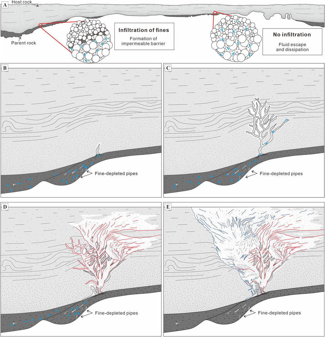
Figure 7. Step-wise evolution model for the funnel-shaped structure. (A) Cross-section showing the parent (dark gray parts: pebble-rich conglomerate) and host (light gray part: coarse sandstone to mudstone) deposits. Insets illustrate sediment grain frameworks with fine-grained particles and fluid (blue) infiltrating interstitial pore spaces. On the left side, selective infiltration promotes the formation of a localized impermeable barrier. In contrast, on the right side, lack of infiltration leads to dissipation of pore fluid. (B) Selective fluidization, forming a clastic dyke. Partial fluidization results in the lateral transport of a mixture of fluids (blue) and fine-grained sediments, forming fine-depleted pipes that act as initial migration pathways. These conduits are likely reactivated and reused during subsequent partial fluidization events. (C) Initial fluidized dyke propagated as a dendritic form. Repeated partial fluidization episodes cause localized enrichment of fine-grained sediments within the previously fluidized dykes or adjacent parent rock. (D) The accumulation of fine-grained sediments forms local impermeable barriers, resulting in re-overpressurization zones. During the second phase of fluidization (red lines), propagation pathways are influenced by the degree of fine-grained sediment infiltration into dyke walls. Where infiltration was sufficient, dykes propagated upward and intersected earlier dykes, producing rhomboid-shaped granule structures. Where infiltration was insufficient, dyke conduits became unstable and deformed into soft-sediment folds or curved string-like geometries. (E) In the third phase of fluidization (blue lines), insufficient infiltration of fine-grained material into the dyke walls led to lateral migration of unstable conduits. This resulted in the formation of faint pipe-shaped dyke-like structures and massive internal sand bodies, particularly toward the left margin of the funnel-shaped structure.
Subsequent loading events then reactivated overpressure in these confined zones, initiating further fluidization and contributing to the formation of a vertically and laterally complex network of clastic dykes. The observed sedimentary structures and cross-cutting relationships within the funnel-shaped structure are consistent with at least three distinct phases of fluidization, described below.
5.3.1 Phase I: initial fluidization and dyke propagation
In the first phase, fluid pressure within the parent rocks exceeded the vertical stress imposed by overlying strata, initiating the upward migration of a sediment-fluid mixture (cf. Dodd et al., 2020; Figure 7B). The mobilized mixture, composed of granule to clay-sized particles, propagated through newly formed conduits. During this process, fine-grained particles infiltrated the surrounding host sediment, forming low-permeability margins that helped sustain internal fluid pressure by reducing lateral leakage (Mount, 1993; Ross et al., 2011). The morphology of the pillar-type structure, characterized by trifurcation (Figure 5H), suggests that the early-stage fluidized dyke may have taken a dendritic form (Figure 7C). The absence of granules in the upper part of the funnel-shaped structure implies that this dendritic pipe did not fully extend upward. Once the internal pressure dissipated, the propagation of the fluidized dykes ceased, and their porosity decreased relative to the parent sediments. This reduction in porosity is attributed to the tighter grain packing and increased fine-grained sediment content (Hurst et al., 2011). The higher content of fine-grained sediments observed within the funnel-shaped structure relative to its parent unit is interpreted as a key factor influencing the post-fluidization rheological behavior. This increase is likely the result of “mechanical memory,” where fine-grained sediments and fluids migrate along the pre-established pathways during successive fluidization events (cf. Sun and Santamarina, 2019).
5.3.2 Phase II: re-fluidization and dyke overprinting
In the second phase, additional loading by frequent mass-transport depositions and continued fine-grained sediment accumulation within the previously fluidized dykes or parent sediment likely led to renewed overpressure (Figure 7D). This overpressure is interpreted to have initiated along the outer edge of the dendritic dyke structure formed during Phase I, particularly at the right margin of the funnel-shaped structure. At this location, renewed fluidization was not accompanied by sufficient infiltration of fine-grained material into the dyke wall. As a result, structural stability was reduced, and a brittle deformation boundary that formed during the first phase was subsequently overprinted by a ductile deformation zone in its upper part. This vertical transition from brittle to ductile deformation reflects the weakening of the dyke wall due to insufficient infiltration of fine-grained sediments.
As fluidization proceeded, expulsion of fine sand-rich sediments occurred along dendritic pathways from previously fluidized parent rock. These fine sand-rich dykes intersected and truncated both the granule-rich dykes formed during Phase I and the soft-deformation zones formed during the early stage of Phase II, segmenting the earlier coarse-grained dykes into isolated rhomboid-shaped patches (Figure 5E). The geometry of these fine sand-rich dykes evolved upward, transitioning from vertical or sub-vertical pipe-like forms in the lower part to curved, string-like morphologies in the upper part of the funnel-shaped structure (Figure 3B). This transition suggests that infiltration of fine-grained sediments into the dyke wall during the second fluidization phase was insufficient to maintain stability of conduit, resulting in the lateral propagation and deformation of the dyke margins (Figure 7D).
5.3.3 Phase III: pipe migration
The third phase is marked by the development of faint pipe-shaped structures composed primarily of medium sand, which intersect earlier fine sand-rich dykes and granule-rich dyke in the left part of the funnel-shaped structure (Figure 5F). These faint pipe-shaped structures likely resulted from insufficient infiltration of fine-grained sediments into the dyke walls. This deficiency may have produced unstable conduits that migrated laterally during fluidization (cf. Ross et al., 2011). This lateral migration obliterated pre-existing structures and generated massive sand bodies in the left part of the funnel-shaped structure (Figure 7E). The increased abundance of massive structure near the left of the funnel-shaped structure suggest that pipe migration may have occurred toward the left. Although many earlier features were erased during this phase, preserved cross-cutting relationships among the faint pipe-shaped structures in the upper part confirm that multiple fluidization events occurred.
Despite this lateral migration and instability, the margin structure on the left exhibits a contrasting characteristic. Notably, the left margin displays a sharp boundary and a relatively narrow fluidization halo compared to the right (Figures 5B,C). Such halos are typically formed by fluid leakage into the host sediments (Mount, 1993). This observation appears contradictory at first, given the instability inferred from the massive structures nearby. However, we interpret that fine-grained sediment infiltration during this phase was spatially variable. While the central parts of the faint pipes remained unstable due to insufficient wall reinforcement, the outer margin of the funnel-shaped structure on the left likely experienced localized and concentrated infiltration of fine-grained material. This enhanced infiltration may have confined fluid flow laterally, suppressing leakage into the host sediment and forming a sharp, well-defined boundary with a thin halo.
The limited vertical extent of the third-phase fluidization is evidenced by the presence of a partially deformed silty layer in the upper part of the funnel-shaped structure. This silty unit likely acted as a mechanical barrier, preventing the fluidized conduits from breaching the uppermost sedimentary cap during this stage.
6 Conclusions
This study presents a detailed sedimentological analysis of an exceptionally well-preserved funnel-shaped fluid-escape structure within the Hakcheon-Chogok Megaturbidite in the Doumsan fan-delta, Southeast Korea. The structure is interpreted as a clastic dyke complex formed through multiple discrete fluidization events. Its formation was closely associated with repeated instantaneous loadings at the base of slope triggered by mass-transport processes along steeply inclined depositional slopes during the fan-delta evolution.
A key factor governing the formation and evolution of the structure was the localized enrichment of fine-grained sediments (<0.25 mm) in both the parent (conglomerate) and host (sand–mud succession) rocks. Selective infiltration of these fine-grained materials produced low-permeability barriers that trapped pore fluids and promoted localized overpressure accumulation. Such infiltration into dyke walls enhanced conduit stability, whereas insufficient infiltration caused lateral migration and deformation of fluidized material, generating massive sand bodies. In addition, the presence of fine-depleted pipes in the parent rock indicates partial fluidization and redistribution of fine particles through elutriation. These elutriated sediments likely re-infiltrated along pre-existing pathways, thereby reinforcing earlier barriers and facilitating recurrent fluidization at similar locations.
Based on the internal cross-cutting relationships and sedimentary compositions of the dyke-like structures, three distinct fluidization phases were identified: Phase I involved the initial upward migration of fluidized granule-to clay-sized sediments, forming dendritic granule-rich dykes stabilized by fine-grained infiltration into dyke walls. Phase II was marked by renewed fluidization from the same source, producing fine sand-rich dykes that intersected earlier dykes and soft-deformation zones. During this phase, insufficient sediment infiltration into dyke walls resulted in laterally unstable and curved pipe structures, accompanied by ductile sediment deformation along dyke margins. Phase III was characterized by lateral migration of medium sand-dominated pipes that crosscut and obliterated earlier structures. Although pipe conduits in this phase were laterally unstable, the sharp left margin and narrow halo are interpreted to result from localized fine-grained infiltration, which confined lateral fluid flow and enhanced boundary definition.
This study reveals that fine-grained sediment redistribution and infiltration dynamically control permeability evolution and overpressure maintenance during the formation of fluid-escape structure. These findings provide a new process-based framework for understanding multiphase fluidization, demonstrating that transient fine-grained barriers, rather than fixed lithologic boundaries, govern the initiation, recurrence, and asymmetry of clastic dyke complexes in subaqueous slope environments.
Data availability statement
The original contributions presented in the study are included in the article/supplementary material, further inquiries can be directed to the corresponding author.
Author contributions
JS: Data curation, Investigation, Conceptualization, Visualization, Writing – original draft, Formal Analysis. IH: Writing – review and editing, Supervision.
Funding
The authors declare that financial support was received for the research and/or publication of this article. This work was supported by the Basic Research Program of the Korea Institute of Geoscience and Mineral Resources (GP 2025-028) funded by the MSIT of the Republic of Korea, the Korea Institute of Energy Technology Evaluation and Planning (KETEP), Ministry of Trade, Industry & Energy, Republic of Korea (No. 20212010200010), and the Korea Agency for Infrastructure Technology Advancement (KAIA) grant funded by the Ministry of Land, Infrastructure and Transport (No. RS-2022-00143541).
Acknowledgments
The authors sincerely thank the reviewers for their constructive comments and insightful suggestions, which greatly improved the clarity and quality of this manuscript.
Conflict of interest
The authors declare that the research was conducted in the absence of any commercial or financial relationships that could be construed as a potential conflict of interest.
Generative AI statement
The authors declare that no Generative AI was used in the creation of this manuscript.
Any alternative text (alt text) provided alongside figures in this article has been generated by Frontiers with the support of artificial intelligence and reasonable efforts have been made to ensure accuracy, including review by the authors wherever possible. If you identify any issues, please contact us.
Publisher’s note
All claims expressed in this article are solely those of the authors and do not necessarily represent those of their affiliated organizations, or those of the publisher, the editors and the reviewers. Any product that may be evaluated in this article, or claim that may be made by its manufacturer, is not guaranteed or endorsed by the publisher.
References
Allen, J. (1982). Sedimentary structures, their character and physical basis volume 1. Amsterdam: Elsevier.
Asghari, M., Yazdanpanah, S., Varkouhi, S., Kadkhodaie, A., and Kianoush, P. (2025). Geohazard impact and gas reservoir pressure dynamics in the zagros fold-thrust belt: an environmental perspective. Geosystems Geoenvironment 4 (2), 100362. doi:10.1016/j.geogeo.2025.100362
ASTM International (2007). ASTM D422-63(2007)e2, standard test method for particle-size analysis of soils. West Conshohocken, PA: ASTM International.
Blott, S. J., and Pye, K. (2001). GRADISTAT: a grain size distribution and statistics package for the analysis of unconsolidated sediments. Earth Surf. Process. Landforms 26 (11), 1237–1248. doi:10.1002/esp.261
Bonini, M. (2019). Seismic loading of fault-controlled fluid seepage systems by great subduction earthquakes. Sci. Rep. 9, 11332. doi:10.1038/s41598-019-47686-4
Cartwright, J., and Santamarina, C. (2015). Seismic characteristics of fluid escape pipes in sedimentary basins: implications for pipe genesis. Mar. Petroleum Geol. 65, 126–140. doi:10.1016/j.marpetgeo.2015.03.023
Chen, J., van Loon, A. J. T., Han, Z., and Chough, S. K. (2009). Funnel-shaped, breccia-filled clastic dykes in the late Cambrian chaomidian formation (shandong province, China). Sediment. Geol. 221, 1–6. doi:10.1016/j.sedgeo.2009.09.006
Chough, S. K., Hwang, I. G., and Choe, M. Y. (1990). The Miocene doumsan fan-delta, southeast Korea; a composite fan-delta system in back-arc margin. J. Sediment. Res. 60, 445–455. doi:10.1306/212F91BA-2B24-11D7-8648000102C1865D
Davies, R. J., Huuse, M., Hirst, P., Cartwright, J., and Yang, Y. (2006). Giant clastic intrusions primed by silica diagenesis. Geology 34, 917–920. doi:10.1130/g22937a.1
Dixon, R., Schofield, K., Anderton, R., Reynolds, A., Alexander, R., Williams, M., et al. (1995). Sandstone diapirism and clastic intrusion in the tertiary submarine fans of the bruce-beryl embayment, quadrant 9, UKCS. Geol. Soc. Lond. Spec. Publ. 94, 77–94. doi:10.1144/gsl.sp.1995.094.01.07
Dodd, T. J., McCarthy, D. J., and Clarke, S. M. (2020). Clastic injectites, internal structures and flow regime during injection: the sea Lion injectite System, north falkland basin. Sedimentology 67, 1014–1044. doi:10.1111/sed.12672
Flemings, P., Long, H., Dugan, B., Germaine, J., John, C., Behrmann, J., et al. (2008). Pore pressure penetrometers document high overpressure near the seafloor where multiple submarine landslides have occurred on the Continental slope, offshore Louisiana, Gulf of Mexico. Earth Planet. Sci. Lett. 269, 309–325. doi:10.1016/j.epsl.2007.12.005
Folk, R. L., and Ward, W. C. (1957). Brazos river bar [texas]; A study in the significance of grain size parameters. J. Sediment. Petrology 27 (1), 3–26. doi:10.1306/74d70646-2b21-11d7-8648000102c1865d
Gihm, Y. S., Kim, S. W., Ko, K., Choi, J.-H., Bae, H., Hong, P. S., et al. (2018). Paleoseismological implications of liquefaction-induced structures caused by the 2017 pohang earthquake. Geosciences J. 22, 871–880. doi:10.1007/s12303-018-0051-y
Goździk, J., and van Loon, A. J. T. (2007). The origin of a giant downward directed clastic dyke in a kame (bełchatów mine, central Poland). Sediment. Geol. 193, 71–79. doi:10.1016/j.sedgeo.2006.02.008
Hurst, A., and Cartwright, J. (2007). “Relevance of sand injectites to hydrocarbon exploration and production,” in Sand injectites: implications for hydrocarbon exploration and production. Editors A. Hurst, and J. Cartwright (Tulsa, Oklahoma: AAPG memoir), 87, 1–19.
Hurst, A., Cartwright, J., Huuse, M., Jonk, R., Schwab, A., Duranti, D., et al. (2003). Significance of large-scale sand injectites as long-term fluid conduits: evidence from seismic data. Geofluids 3, 263–274. doi:10.1046/j.1468-8123.2003.00066.x
Hurst, A., Scott, A., and Vigorito, M. (2011). Physical characteristics of sand injectites. Earth-Science Rev. 106, 215–246. doi:10.1016/j.earscirev.2011.02.004
Huuse, M., Duranti, D., Steinsland, N., Guargena, C. G., Prat, P., Holm, K., et al. (2004). Seismic characteristics of large-scale sandstone intrusions in the Paleogene of the south Viking graben, UK and Norwegian north Sea. Geol. Soc. Lond. Memoirs 29, 263–278. doi:10.1144/gsl.mem.2004.029.01.25
Hwang, I. G., Chough, S. K., Hong, S. W., and Choe, M. Y. (1995). Controls and evolution of fan delta systems in the Miocene pohang basin, SE Korea. Sediment. Geol. 98, 147–179. doi:10.1016/0037-0738(95)00031-3
Hwang, I. G., Son, J., and Cho, S. (2021). Event stratigraphy of yeonil group, Pohang basin: based on correlation of 21 deep cores and outcrop sections. J. Geol. Soc. Korea 57, 649–678. doi:10.14770/jgsk.2021.57.5.649
Jonk, R. (2010). Sand-rich injectites in the context of short-lived and long-lived fluid flow. Basin Res. 22, 603–621. doi:10.1111/j.1365-2117.2010.00471.x
Jonk, R., Duranti, D., Hurst, A., Parnell, J., and Fallick, A. (2007). Aqueous and petroleum fluids associated with sand injectites hosted by lacustrine shales from the oil-shale group (dinantian), Midland valley, Scotland. Sand injectites: implications for hydrocarbon exploration and production. Editors A. Hurst, and J. Cartwright (Tulsa, Oklahoma: AAPG memoir), 87, 265–274. doi:10.1306/1209870m873267
Kane, I. A. (2010). Development and flow structures of sand injectites: the hind sandstone member injectite complex, Carboniferous, UK. Mar. Petroleum Geol. 27, 1200–1215. doi:10.1016/j.marpetgeo.2010.02.009
Kim, W. H. (1990). Significance of early to middle Miocene planktonic foraminiferal biostratigraphy of the E-core in the pohang Basin, Korea. J. Paleontol. Soc. Korea 6 (2), 144–164.
Lowe, D. R. (1975). Water escape structures in coarse-grained sediments. Sedimentology 22, 157–204. doi:10.1111/j.1365-3091.1975.tb00290.x
Lowe, D. R. (1982). Sediment gravity flows: II. Depositional models with special reference to the deposits of high-density turbidity currents. SEPM J. Sediment. Res. 52 (1), 279–297. doi:10.1306/212F7F31-2B24-11D7-8648000102C1865D
Lupini, J. F., Skinner, A. E., and Vaughan, P. R. (1981). The drained residual strength of cohesive soils. Géotechnique 31, 181–213. doi:10.1680/geot.1981.31.2.181
Massari, F., Ghibaudo, G., D'alessandro, A., and Davaud, E. (2001). Water-upwelling pipes and soft-sediment-deformation structures in lower Pleistocene calcarenites (salento, southern Italy). Geol. Soc. Am. Bull. 113, 545–560. doi:10.1130/0016-7606(2001)113<0545:wupass>2.0.co;2
Mörz, T., Karlik, E. A., Kreiter, S., and Kopf, A. (2007). An experimental setup for fluid venting in unconsolidated sediments: new insights to fluid mechanics and structures. Sediment. Geol. 196, 251–267. doi:10.1016/j.sedgeo.2006.07.006
Mount, J. F. (1993). Formation of fluidization pipes during liquefaction: examples from the uratanna formation (lower Cambrian), South Australia. Sedimentology 40, 1027–1037. doi:10.1111/j.1365-3091.1993.tb01378.x
Nermoen, A., Galland, O., Jettestuen, E., Fristad, K., Podladchikov, Y., Svensen, H., et al. (2010). Experimental and analytic modeling of piercement structures. J. Geophys. Res. Solid Earth 115. doi:10.1029/2010jb007583
Netoff, D. I., and Shroba, R. R. (2001). Conical sandstone landforms cored with clastic pipes in glen canyon National recreation Area, southeastern Utah. Geomorphology 39, 99–110. doi:10.1016/s0169-555x(00)00096-9
Nichols, R. J., Sparks, R. S. J., and Wilson, C. J. N. (1994). Experimental studies of the fluidization of layered sediments and the formation of fluid escape structures. Sedimentology 41, 233–253. doi:10.1111/j.1365-3091.1994.tb01403.x
Obermeier, S. F. (1996). Use of liquefaction-induced features for paleoseismic analysis—an overview of how seismic liquefaction features can be distinguished from other features and how their regional distribution and properties of source sediment can be used to infer the location and strength of Holocene paleo-earthquakes. Eng. Geol. 44, 1–76. doi:10.1016/s0013-7952(96)00040-3
Peterson, G. L. (1968). Flow structures in sandstone dikes. Sediment. Geol. 2, 177–190. doi:10.1016/0037-0738(68)90024-9
Phillips, E., Everest, J., and Reeves, H. (2013). Micromorphological evidence for subglacial multiphase sedimentation and deformation during overpressurized fluid flow associated with hydrofracturing. Boreas 42, 395–427. doi:10.1111/j.1502-3885.2012.00261.x
Pisarska-Jamroży, M., and Weckwerth, P. (2013). Soft-sediment deformation structures in a Pleistocene glaciolacustrine delta and their implications for the recognition of subenvironments in delta deposits. Sedimentology 60 (3), 637–665. doi:10.1111/j.1365-3091.2012.01354.x
Pisarska-Jamroży, M., Belzyt, S., Börner, A., Hoffmann, G., Hüneke, H., Kenzler, M., et al. (2019). The sea cliff at dwasieden: soft-sediment deformation structures triggered by glacial isostatic adjustment in front of the advancing Scandinavian ice sheet. DEUQUA Spec. Publ. 2, 61–67. doi:10.5194/deuquasp-2-61-2019
Postma, G. (1983). Water escape structures in the context of a depositional model of a mass flow dominated conglomeratic fan-delta (abrioja formation, Pliocene, Almeria basin, SE Spain). Sedimentology 30, 91–103. doi:10.1111/j.1365-3091.1983.tb00652.x
Ravier, E. (2024). Physical characteristics of hydrofracture systems and their fills in glacial sediments. Sediment. Geol. 463, 106593. doi:10.1016/j.sedgeo.2024.106593
Roche, O., Druitt, T. H., and Cas, R. A. (2001). Experimental aqueous fluidization of ignimbrite. J. Volcanol. Geotherm. Res. 112, 267–280. doi:10.1016/s0377-0273(01)00246-3
Ross, J. A., Peakall, J., and Keevil, G. M. (2011). An integrated model of extrusive sand injectites in cohesionless sediments. Sedimentology 58, 1693–1715. doi:10.1111/j.1365-3091.2011.01230.x
Son, J., Cho, S., and Hwang, I. G. (2024). The hakcheon-Chogok megaturbidite in the Miocene Pohang-Youngduk Basin, SE Korea: high-gradient slope failure probably triggered by a giant tsunami wave. Geosciences J. 28, 301–318. doi:10.1007/s12303-024-0004-6
Sun, Z., and Santamarina, J. C. (2019). Grain-displacive gas migration in fine-grained sediments. J. Geophys. Res. Solid Earth 124, 2274–2285. doi:10.1029/2018jb016394
Syvitski, J. P. (1991). Principles, methods, and application of particle size analysis, 388. Cambridge: Cambridge University Press.
Talling, P. J., Clare, M. A., Hughes Clarke, J., Pope, E. L., Hunt, J., and Lintern, D. (2021). Subaqueous sediment density flows: depositional processes and deposit types. Sedimentology 68 (9), 2208–2259. doi:10.1111/sed.12808
van der Meer, J. J., Kjær, K., Krüger, J., Rabassa, J., and Kilfeather, A. (2009). Under pressure: clastic dykes in glacial settings. Quat. Sci. Rev. 28, 708–720. doi:10.1016/j.quascirev.2008.07.017
Varkouhi, S., Tosca, N. J., and Cartwright, J. A. (2020). Pore-water chemistry: a proxy for tracking the signature of ongoing silica diagenesis. J. Sediment. Res. 90 (9), 1037–1067. doi:10.2110/jsr.2020.56
Varkouhi, S., Tosca, N., Cartwright, J., Guo, Z., Kianoush, P., and Jurkowska, A. (2024). Pore water chemical constraints on petrophysical shifts following biosilica diagenesis. Geochem. Perspect. Lett. 32, 39–45. doi:10.7185/geochemlet.2440
Wattrus, N. J., Rausch, D., and Cartwright, J. (2003). Soft-sediment deformation in Lake Superior: evidence for an immature polygonal fault system? Geol. Soc. 216, 323–334. doi:10.1144/gsl.sp.2003.216.01.21
Wentworth, C. K. (1922). A scale of grade and class terms for clastic sediments. J. Geol. 30 (5), 377–392. doi:10.1086/622910
Yazdanpanah, S., Arjomand, E., Rahmani, R., Maleki, R., and Kianoush, P. (2025). Biostratigraphy and microfacies analysis of the jahrum Formation in the interior Fars Province, folded Zagros Region, SW Iran. Solid Earth Sci. 10 (2), 100241. doi:10.1016/j.sesci.2025.100241
Keywords: fluid-escape structure, funnel-shaped structure, hydrofracture, infiltration, discrete fluidization, clastic dyke complexes
Citation: Son J and Hwang IG (2025) Funnel-shaped fluid-escape structure: a clastic dyke complex formed by multiple, discrete fluidizations. Front. Earth Sci. 13:1677667. doi: 10.3389/feart.2025.1677667
Received: 01 August 2025; Accepted: 07 November 2025;
Published: 01 December 2025.
Edited by:
Ángel Puga-Bernabéu, University of Granada, SpainReviewed by:
Pooria Kianoush, Islamic Azad University South Tehran Branch, IranMalgorzata Pisarska Jamrozy, Uniwersytet im Adama Mickiewicza w Poznaniu Instytut Geologii, Poland
Copyright © 2025 Son and Hwang. This is an open-access article distributed under the terms of the Creative Commons Attribution License (CC BY). The use, distribution or reproduction in other forums is permitted, provided the original author(s) and the copyright owner(s) are credited and that the original publication in this journal is cited, in accordance with accepted academic practice. No use, distribution or reproduction is permitted which does not comply with these terms.
*Correspondence: In Gul Hwang, aWdod2FuZ0BraWdhbS5yZS5rcg==