 Adam Wójcicki
- Polish Geological Institute-National Research Institute, Warsaw, Poland
This study builds on the findings of the CCUS ZEN project by focusing on the local storage options of one of the value chains considered in that study, located in the region of northern Poland. Storage options include potential sites in saline aquifers, both onshore and offshore, which have already been screened, selected and evaluated in previous domestic and European projects. The reservoir and caprock parameter data from the literature has been harmonised and validated. The associated uncertainties, knowledge gaps and risks have also been addressed. The standard CSLF methodology for estimating volumetric (static) storage capacity and the Monte Carlo method were used. The storage efficiency factor was then estimated using data on CO2 injection simulations from the literature. Taken together, these steps go beyond the evaluations carried out in previous projects for these sites. The study shows that deploying and developing such a relatively immature value chain necessitates the integration of technical and non-technical elements, such as legal, social, and policy frameworks. Its focus is specifically on using the local potential for CO2 storage as an alternative and supplementary measure to shipping. For CCUS planning in Central Europe, it is important that the value chain includes a CO2 import-export terminal in the Port of Gdańsk. This terminal will eventually be connected to offshore and onshore storage sites via pipelines. The value chain could also be expanded to connect more emission sources and storage sites. This could potentially form part of future regional and pan-European CO2 storage and CCS infrastructure.
1 Introduction
In the context of the industry’s decarbonisation efforts, there has been significant research and development in CCS/CCUS technologies. Numerous studies have been conducted worldwide over the past few decades to assess the potential for CO2 storage and to explore source-to-sink scenarios. A number of regional and case studies were conducted in Europe as part of the GESTCO (Christensen and Larsen, 2004), EU GeoCapacity (Vangkilde-Pedersen et al., 2009), NORDICCS (Anthonsen et al., 2014; Lothe et al., 2016), CO2StoP project (Poulsen et al., 2015) and STRATEGY CCUS (Veloso, 2021) projects. These studies included an assessment of CO2 storage potential, site screening and preliminary selection, and an evaluation that took into account associated uncertainties. Standardized methodologies and data on specific countries, provided by project partners, were used for these studies. They also explored source-to-sink scenarios. Research in this field has been conducted in numerous domestic and European projects in Poland (e.g., van Bergen et al., 2003; Tarkowski et al., 2006; Willscher et al., 2008; Tarkowski et al., 2009; Dziewińska et al., 2010; Michna and Papiernik, 2012; Wójcicki and Pacześna, 2013; Wójcicki et al., 2014; Wójcicki et al., 2021; Klimkowski et al., 2015; Lubaś et al., 2015; Urych and Smoliński, 2019; Urych et al., 2022; Luboń, 2020; 2021; Szott and Miłek, 2021; Śliwińska et al., 2022; Wojnicki et al., 2023; Miecznik et al., 2025). Nooraiepour et al. (2025) recently summarised studies on CO2 storage for Poland. As CCS/CCUS technologies continue to advance, the development of CCS/CCUS value chains is increasingly focusing on the integration of industrial emitters with transport and storage hubs and networks (e.g., GCCSI, 2024).
In the CCUS ZEN (Zero Emission Network to facilitate CCUS uptake in industrial clusters) project studies on the development of the CCS/CCUS value chains were carried out. These studies involved integrating clusters of industrial emitters with transport networks and storage hubs in saline aquifers in the regions of the Baltic Sea and the Mediterranean Sea. The CCUS developments in the North Sea region were used as the best practice for the development of new CCUS value chains in both these less developed regions (CCUS ZEN, 2025; Lothe et al., 2025). The CCUS ZEN project considered one of the value chains, which included emission sources in northern Poland, as well as local transport and storage options (Lothe et al., 2025; Wójcicki, 2025).
This paper focuses on the storage part of the value chain, where data from literature have been harmonized and validated. The uncertainties, knowledge gaps, and risks related to the use of storage sites in saline aquifers that were screened, selected, and evaluated in previous domestic and European projects are addressed. Chapter 1.1 briefly characterises the value chain, and Chapter 1.2 presents the geological background, focusing on the storage potential within a broader context. Chapter 2 focuses on knowledge gaps and uncertainties related to the standard volumetric storage capacity assessment used in the CCUS ZEN project and this study. Chapter 3 evaluates storage potential and discusses related uncertainties and sensitivities. This evaluation uses standard Monte Carlo and volumetric storage capacity assessment methodologies and literature. In Chapter 4, risks and barriers pertaining to the implementation of the value chain, particularly the storage part, are discussed.
1.1 The value chain
There are 27 emitters in the area with a capacity of at least 0.1 Mtpa each (Figure 1; Wójcicki, 2025). The total capacity is around 22.7 Mtpa. These facilities include refineries, chemical plants, paper and pulp mills, cement production sites and lime kilns, as well as energy industry installations. Excluding old coal-fired energy installations, 16 installations remain, with a total capacity of 14.8 Mtpa (Table 1). The CCUS ZEN value chain in northern Poland is linked to the scope of the ECO2CEE Project of Common Interest (PCI) on CO2 terminal in the Port of Gdańsk (Figure 1; Orlen, 2024), as two of these emission sources are also considered in the PCI. In the initial phase of the ECO2CEE project, which is scheduled to run until 2030, the focus will be on integrating the transport of captured CO2 by rail from two locations (marked in blue in Figure 1) within the value chain to the terminal: the Orlen Płock refinery (1 Mtpa) and the Holcim cement plant (1 Mtpa; Orlen, 2024). Carbon dioxide delivered to the terminal by rail will be transported by sea and stored in geological structures beneath the North Sea.
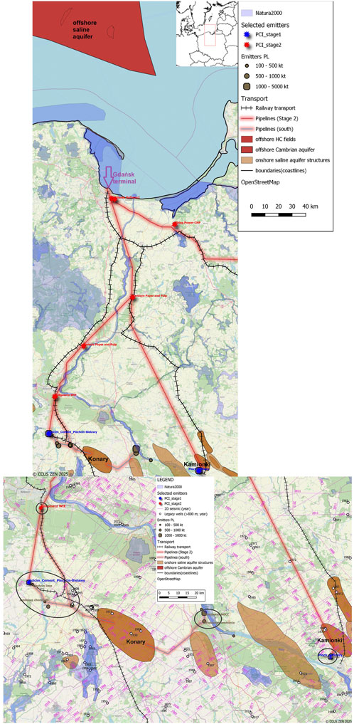
Figure 1. The possible integration of the value chain into the next stage of the PCI project (based on Wójcicki, 2025; the southernmost part is enlarged at the bottom). The labelled emitters (in the subclusters encircled) and structures are preferred components of the value chain.
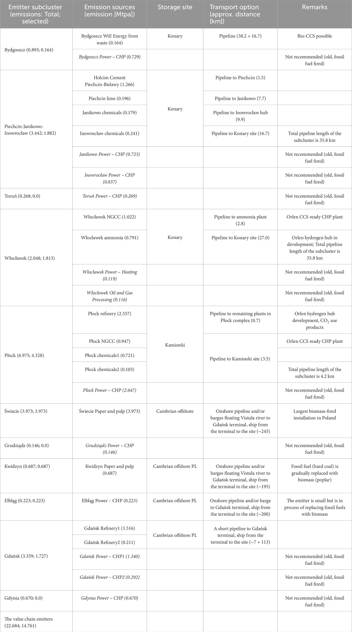
Table 1. The proposed storage and transport options for the value chain subclusters (after Wójcicki, 2025). Figure 1 shows the locations.
However, there is significant storage potential in the region, particularly in the onshore and offshore saline aquifers, which is likely to be sufficient to store CO2 emissions from local sources. Depending on the timeframe, emitter and storage site locations, and volumes of captured carbon dioxide, transport options might include railway, pipelines and/or ship/barge delivery (Gravaud et al., 2023). The current legal framework in Poland allows permits for CO2 storage to be applied for only in an offshore area (The Ordinance, 2014). However, Article 11 of the Helsinki Convention currently prohibits the storage of CO2 under the Baltic Sea seabed, and is to be amended (Wammer Østgaard, 2024). The revision of the regulation allowing onshore CO2 storage in Poland is to be published soon. Regulations on onshore CO2 transport, particularly those relating to the construction and operation of CO2 pipelines, are currently being drafted. It is therefore proposed that the next stages of the PCI project include additional CO2 emitters from the value chain (see Figure 1). At the same time, it is proposed that the original concept of the PCI be supplemented and enhanced by the introduction of additional transport and storage options.
1.2 Geological background with focus on storage potential
The reservoirs and relevant caprocks of the considered onshore saline aquifer structures are within Lower to Middle Jurassic and Cretaceous formations (Dziewińska et al., 2010; Wójcicki et al., 2014). The Lower to Middle Jurassic formations cover more than half of Poland’s territory. They are the easternmost part of the Central European Basin System (CEBS; Pieńkowski and Schudack, 2008) and consist of several regional complexes primarily made up of lacustrine, fluvial, shallow marine and deltaic sandstones. These sandstones have usually good reservoir properties. The reservoirs are accompanied by several regional caprock complexes, primarily composed of claystones, mudstones and shales of marine origin. The CEBS includes similar (though not always contemporary) reservoir and caprock formations, present in northern Germany, Denmark, the Netherlands and as far as eastern France, northern Switzerland and parts of England (Pieńkowski and Schudack, 2008). Regional formations of black shales, resulting from marine anoxic events, have the potential to serve as reliable caprocks. For instance, the Lower Toarcian Posidonia shales and their equivalents, which are present in a large part of the CEBS (Pieńkowski and Schudack, 2008; Hesselbo and Pieńkowski, 2011; Pieńkowski, 2015) are of proven very low permeability (Ladage, 2016). The Cretaceous formations considered in the value chain comprise Lower Cretaceous reservoirs, which are primarily made up of sandstones of shallow marine and deltaic origin. The caprock formation comprises thick sequences of Upper Cretaceous limestone, marly limestone, opoka, mudstone and claystone (Dziewińska et al., 2010). These are all of shallow marine or carbonate shelf origin. Similar formations, though not always contemporary, are present in parts of Poland, northern Germany and Denmark (Voigt and Wagreich, 2008; Ladage, 2016; Hjelm et al., 2020).
Another storage option within the value chain is the offshore Cambrian saline aquifer in the north-eastern part of Poland’s Baltic Sea sector. This contains several relatively small hydrocarbon fields. The reservoirs (Semyrka et al., 2010) are primarily composed of Middle Cambrian sandstones of shallow marine, clastic origin, while the caprock comprises a thick, claystone-shale-carbonate sequence of Upper Cambrian, Ordovician, and Silurian rocks of marine origin. The aquifer is part of the Cambrian sandstone formation, which can be found in the south-eastern Baltic Sea and the surrounding land areas (Nilsson, 2014; Vernon et al., 2013; Mortensen and Sopher, 2021). The primary seal of the Cambrian sandstone reservoir is the Alum Shale Formation, or equivalent formations of the Upper Cambrian and Lower Ordovician periods, which are proven to have very low permeability (Poprawa, 2020; Schulz et al., 2021).
2 Method, materials and knowledge gaps
2.1 Emission sources and transport options
The inventory of industrial emission sources was completed in the CCUS ZEN project (Ringstad et al., 2023; Lothe et al., 2024; 2025; CCUS ZEN website). The Polish part of the pan-European database provided by one of the project partners (ENDRAVA) was verified, updated and amended using data from the European Union Registry (European Commission, 2025), previous projects (e.g., Tarkowski et al., 2009; Wójcicki et al., 2014) as well as company websites and press releases. The relevant information on the emitters in the studied region is included in Table 1.
The transport routes presented in Figure 1 have been drawn using the CCUS ZEN GIS project (Ringstad et al., 2023; Gravaud et al., 2023). The GIS included the publicly available existing gas pipeline and railway routes, as well as nature protected areas. These features have been taken into consideration when drawing the proposed transport routes. According to Ho et al. (2024), the rail transport of liquefied carbon dioxide is safer than onshore pipeline and truck transport when the number of incidents in the US between 2003 and 2023 is considered. The volume of CO2 released in railway incidents per year is also over sixty times smaller than in pipelines. However, it should be noted that rail transport is used for smaller amounts of CO2 over shorter distances than pipelines. The adaptation of legacy gas pipelines was excluded from this study. It was assumed that using the existing pipeline routes would make designing the new ones easier. Neither the CCUS ZEN project nor this study considered the technical specifications of new pipelines for the value chain. However, to avoid pipeline corrosion, the CO2 stream must not contain any significant quantities of certain admixtures, particularly water, as well as SOx, O2, NOx and H2S, which could form corrosive acids and solutions. Danish Energy Agency (2024), the Northern Lights project specifications require that the CO2 stream delivered to the pipeline eventually includes: H2O ≤ 30 ppm, O2 ≤ 10 ppm, SOx ≤ 10 ppm, NOx ≤ 10 ppm and H2S ≤ 9 ppm.
2.2 Storage potential
In the CCUS ZEN project, potential storage sites that had been screened and selected in previous European and national projects within the considered regions were described and evaluated (Lothe et al., 2024; 2025). This evaluation was focused particularly on saline aquifers, which are the option with the highest storage potential. This included indicating the maturity of the storage site capacity evaluation, as defined by Akhurst et al. (2021). The standard CSLF methodology for the volumetric (static) storage capacity assessment of saline aquifers (after Vangkilde-Pedersen et al., 2009) was applied using the following formula:
where:
MCO2: regional or trap aquifer storage capacity,
A: area of regional or trap aquifer,
h: average thickness of regional or trap aquifer,
NG: average net to gross ratio of regional or trap aquifer,
ϕ: average reservoir porosity of regional or trap aquifer,
ρCO2r: CO2 density at reservoir conditions,
Seff: storage efficiency factor.
For regional saline aquifers, the recommended storage efficiency factor is approximately 2%. For traps, the recommended storage efficiency values for semi-closed low-quality and open high-quality reservoirs are between 3% and 40%, respectively (Vangkilde-Pedersen et al., 2009). This factor implicitly considers the effects of non-reducible water saturation, and likely capillary trapping, in addition to structural and hydrodynamic trapping. Thus, it is equivalent to the US Department of Energy methodology (Goodman et al., 2011), which uses injection simulation results and related uncertainties to estimate the factor.
A similar approach was applied in the recent study on CO2 storage potential in Denmark (Hjelm et al., 2020), but the modified storage efficiency factor excluding reservoir volume below the spill point and the CO2-water contact was considered. Furthermore, the Monte-Carlo simulation method was employed to assess the capacity uncertainty range. Bachu (2015) highlighted that the CSLF approach might lack reliability unless it is validated by CO2 injection simulations for the storage site’s lifetime and beyond (dynamic storage capacity). Recent CSLF studies (CSLF, 2019; CSLF, 2021) emphasize the importance of validating the approach using injection simulations and field injection data. In addition to the structural, stratigraphic, hydrodynamic and capillary trapping mechanisms, they also recommend considering the dissolution and solubility, as well as the mineral trapping, mechanisms to ensure the safe storage of CO2 in the storage complex. It should be noted that different time scales apply to the respective mechanisms, depending on the storage complex’s lithology. For example, the mineral trapping mechanism is negligible in the short term in sandstone reservoirs, which are considered in this study. On the other hand, mineral CO2 trapping is a dominant, relatively short-term storage mechanism in saline aquifers in mafic basaltic formations because these rocks are composed of highly reactive minerals such as plagioclase, wollastonite, pyroxene, and olivine (Al Maqbali et al., 2023). Another story is the in situ CO2-EOR operation involving the interaction of fluids within an oil field (Hussain et al., 2021). In this process, temperature controls the rate at which a CO2-generating chemical agent hydrolyses, as well as the solubility of CO2 in the oil and water phases (Hussain et al., 2023).
The most recent reports from the International Energy Agency’s Greenhouse Gas R&D Programme (IEAGHG, 2024; 2025) summarise and discuss current global developments in the field of safety evaluation of CO2 geological storage in saline aquifers. They emphasise the importance of evaluating the containment of the storage site, taking into account factors such as seal capacity, hydraulic fractures, fault sealing and overpressure caused by CO2 injection in the models, as well as the integrity of new and legacy wells. Large-scale CO2 storage requires modelling the capacity and integrity of the storage complex over the long term, at both local and larger scales. This involves considering multiple reservoirs, caprocks and faults in the local area and beyond (Gilmore et al., 2022; Kivi et al., 2022). Seal capacity assessment involves more than measuring capillary breakthrough pressure, wettability, and the impact of injected CO2 temperature (Espinoza and Santamarina, 2017). Knowledge of in situ stress is crucial and can be obtained through borehole geomechanical testing. Together with well logging, laboratory testing of rock samples, and seismic interpretation, borehole geomechanical testing can provide input for geomechanical modeling (Thompson et al., 2022). Another important factor is the long-term impact of geochemical reactions between CO2, brine, and caprock on sealing mechanisms. In some cases, these reactions may improve the sealing properties of the caprock (Yang et al., 2020). Minerals that are particularly susceptible to dissolution include calcite, olivine, pyroxene, anorthite, and berthierine (Watson, 2012). The presence of existing faults or fractures, which form during or after the injection period, may expedite geochemical reactions and caprock disintegration due to CO2 flow (Dean et al., 2020; IEAGHG, 2024). The complexity of the interaction between chemical, mechanical, hydraulic, and thermal aspects, as presented above, requires a comprehensive modeling approach to address caprock integrity during long-term CO2 storage (IEAGHG, 2024). This approach may involve coupling or sequencing the modelled processes (Alsayah and Rigby, 2023; Yong et al., 2019).
In this study the standard CSLF methodology for the volumetric (static) storage capacity assessment of saline aquifers was used as well. The structures considered in this study were screened, selected and evaluated in previous domestic and European projects (Tarkowski et al., 2009; Vangkilde-Pedersen et al., 2009; Dziewińska et al., 2010; Wójcicki et al., 2014; Poulsen et al., 2015; Lothe et al., 2025), in which the same methodologies for assessing volumetric storage capacity were employed. The selection of suitable structures in saline aquifers was based on the guidelines set out by Chadwick et al. (2008). Chadwick et al. (2008) state that the key geological indicators for determining the suitability of a storage site include caprock efficacy, reservoir efficacy and properties. The caprock efficacy considers such parameters as the lateral continuity, thickness and capillary breakthrough pressure of rocks deemed to be sufficiently impermeable. In this study, data from literature, including the results of these previous projects and other publications, have been harmonised and validated. The relevant results of the reservoir simulations (Luboń, 2020; Luboń, 2021; Wojnicki et al., 2023) were used to estimate the storage efficiency factor in the volumetric storage capacity assessment. Chapter 2.1 presents information and data on the capillary breakthrough pressure of Jurassic and other Mesozoic caprocks in the Polish Basin, as well as the permeabilities of caprock analogs. The data range of the capillary breakthrough pressure is consistent with the values assumed in the reservoir simulations of Luboń (2020), Luboń (2021). Chapter 2.1 also discusses laboratory experiments and long-term geochemical simulations of the brine-rock-CO2 system, which were conducted using rock samples from Mesozoic aquifers and caprocks from the Polish Basin. The results suggest that the contribution of mineral trapping to storage capacity is significant only over timeframes measured in thousands of years. Therefore, this mechanism was not considered in the storage efficiency factor in this study. The results also suggest that the long-term impact of geochemical reactions on the reservoir and caprock sealing properties is not significant. However, there are no published results from geomechanical modelling of sites with similar geological conditions. Furthermore, there are no relevant simulations that take into account the interaction between the chemical, mechanical, hydraulic and thermal aspects of storage complexes during and after injection.
Standard Monte Carlo method was used with the simulation tool built in the open source Gnumeric software (Baudais et al., 2012). Simple distributions available in the software were used as input for the simulations, i.e., a normal distribution was assumed for all parameters except porosity, which was lognormal. The estimated uncertainty ranges correspond to ±3 standard deviations from the mean values of the parameter distributions. The CSLF formula presented above was implemented in the simulation tool. To achieve stable and sufficient statistical representation of both input distribution and result output, 10,000 iterations were calculated for each simulation.
Therefore, the general conclusion is that the sites considered in this study are quite immature according to the standards defined by Akhurst et al. (2021). In other words, the findings of this study may help plan the appraisal phase. The recent developments in storage safety evaluation should be considered during the appraisal and characterisation phases. Due to concerns raised by stakeholders about the safety of CO2 storage, the issue of the long-term integrity of the seal should be addressed during the appraisal and characterisation phases.
2.3 Review of knowledge about seal quality and storage complex reactivity relevant to the considered storage sites
2.3.1 Seal quality
According to the literature, the primary seal permeability is generally assumed to be in the micro- to nano-Darcy range. However, a value that is too low could cause excessive pressure (Bachu, 2015; Espinoza and Santamarina, 2017; Rackley and Rackley, 2017). Therefore, the practical range of this parameter could be 0.0001–0.005 mD. However, these values are below the accuracy of the mercury porosimetry method, which was commonly used for samples from legacy wells.
Such low permeabilities have been particularly measured on gas-bearing shale samples where methods employing various gases instead of mercury are used (Schulz et al., 2021). Methods of determining the capillary breakthrough pressure of caprock samples at simulated reservoir conditions (Soomro et al., 2025) generally rely on similar assumptions. Therefore, both permeability and capillary breakthrough pressure values were determined in laboratory experiments for a limited number of fine-grained caprock samples in the Polish national project. These experiments suggest that the capillary breakthrough pressures of the main (onshore) caprocks in the Polish basin exceed 25% of the relevant reservoir pressures. In other words, the capillary pressures are within the range of 2.6–7.2 MPa at a reservoir depth of 1–2 km, with a pressure close to the hydrostatic pressure (Smulski et al., 2013). The measured permeabilities of these caprocks are in the micro-Darcy range. This means that they make a good containment provided there is no faulting. Studies on Posidonia shale of Lower Jurassic in Germany, which is an equivalent of one of principal caprocks in the Polish basin, also suggest the permeability in the micro-Darcy range (Ladage, 2016). The measured permeabilities of the Upper Cambrian-Ordovician shales, which form the caprock for the Middle Cambrian aquifer in the Baltic basin, are even one order of magnitude lower (Poprawa, 2020; Schulz et al., 2021). This means they could make even better containment.
2.3.2 Geochemical analyses and modelling
Tarkowski and Wdowin (2011) carried out laboratory experiments on the interactions between injected CO2, rocks and brines, using rock samples from Lower Cretaceous and Lower Jurassic sandstone reservoirs and carbonate caprocks from the Polish Basin. The experiments did not significantly worsen the reservoir properties of the rocks. These likely slightly improved the sealing capacity of the caprocks. Several studies have carried out long-term geochemical simulations of the brine-rock-CO2 system in Jurassic sandstone reservoirs and claystone caprocks, based on laboratory analyses and experiments (e.g., Tarkowski et al., 2011; Labus et al., 2014). According to these findings, the disintegration of kaolinite slightly increases the reservoir’s porosity at the start of the 20,000-year modeling period. Then, the precipitation and crystallisation of carbonate minerals decrease porosity, which remains relatively unchanged for the rest of the period. During this time, kaolinite, chalcedony and quartz recrystallise. In the caprock, plagioclase dissolution is followed by beidellite and gibbsite crystallisation, then by carbonate minerals and kaolinite crystallisation. During the 20,000-year modeling period, it was estimated that trapping in carbonate minerals (dawsonite, calcite, siderite, and dolomite) could sequester up to 12 kg of CO2 per cubic meter of formation in reservoirs and up to 15.4 kg of CO2 per cubic meter of caprock. These processes do not significantly impair the properties of the reservoir rocks and may even slightly enhance the sealing properties of the caprock (Tarkowski et al., 2011; Labus et al., 2014).
The results of these studies are broadly consistent with existing knowledge of the mineral composition of the reservoirs in question, particularly with regard to the presence of reactive minerals (Kozłowska and Kuberska, 2014). In Jurassic sandstone reservoirs, calcite appears as a small admixture in the cement that binds the matrix of clay minerals and larger grains together. This cement typically consists of quartz, siderite, and ankerite. The grains are mostly composed of quartz and alkali feldspar and occasionally contain plagioclase and mica.
3 Results
3.1 Onshore CO2 storage options
The southern part of the value chain area (Figure 1), where two ECO2CEE emitters and several others are located, contains several saline aquifer structures in Jurassic and Lower Cretaceous sandstones of good reservoir quality. These structures were screened, selected, and evaluated in previous domestic and European projects.
Published data on the results of reservoir tests of Lower and Middle Jurassic sandstones, and Lower Cretaceous sandstones, carried out using formation testers, are available for several wells located within the area (Dembowska and Marek, 1985; Feldman-Olszewska, 2007; Feldman-Olszewska, 2008). Brine yields of 0.9–14.96 m3/h were reported in the Lower Jurassic sandstones, 3.55–30 m3/h in the Middle Jurassic, and around 30 m3/h in the Lower Cretaceous. These results confirm the quality of reservoirs. In the SSE part of the area, gas and oil shows have been observed in the Jurassic and Cretaceous formations. No meaningful overpressure is observed within these reservoirs.
The estimated volumetric storage capacities of these structures, calculated in several projects using the CSLF methodology (Tarkowski et al., 2009; Dziewińska et al., 2010; Wójcicki et al., 2014; Poulsen et al., 2015; Ringstad et al., 2023), are significantly exceeding the possible demand of all emitters of the local cluster (Table 1), i.e., the estimated volumetric capacity of all the onshore structures shown in Figure 1 is within the approximate range of 1.5–2 Gt. Due to the proximity of the emitters and potential storage sites, the development of storage and transport infrastructure could be relatively cost-effective in this area.
Two saline aquifer structures, Konary and Kamionki, have been identified as potential storage sites within the value chain. Both structures are located in close proximity to CO2 emitter subclusters (see Figure 1). There are no protected areas or major settlements above the structures, nor are there any conflicting activities above the storage complex. At the fully industrial stage of the value chain, transport via new onshore pipelines is proposed. In the event of the pilot injection or at the preliminary stage, railway or road transport might be a viable option. Depending on the particular emitters and emitter subclusters in question, the estimated length of pipeline sections in the southern part of the region ranges from 4.2 to 38.2 km (Table 1). The Konary structure is proposed as the storage site for three nearby subclusters. One is located to the west and incorporates the Holcim cement plant, which is included in the first stage of the ECO2CEE PCI project. Another is located north-west, and the last is to the east of the structure (Figure 1). The Kamionki structure is proposed for use as the storage site for the nearby emitter subcluster, which includes, among other elements, the Orlen Płock refinery. The refinery is scheduled to be in the first stage of the ECO2CEE PCI.
3.1.1 The Konary structure
The Konary structure is a brachyanticline that was formed above a Zechstein salt pillow. It encompasses a multi-reservoir Jurassic aquifer (Figures 2A,B). This aquifer consists of sandstones from the Lower Aalenian, Upper Toarcian, Pliensbachian, and Sinemurian periods. These sandstones are separated by seals or aquitards. However, the Lower Aalenian-Upper Toarcian reservoir exceeds the CO2 supercritical range at the structure’s summit (Luboń, 2020; Wójcicki et al., 2014; Figures 2B–D), so only Pliensbachian and Sinemurian reservoirs are considered. The primary caprock/seal consists of Lower Toarcian black shales (i.e., claystones and mudstones), while the additional seals comprise Bajocian and Upper Aalenian claystones and mudstones, as well as Bathonian claystones (Figure 2B).
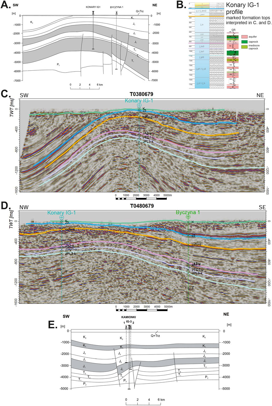
Figure 2. (A) A schematic geological section of the Konary structure (after Dziewińska et al., 2010). (B) The stratigraphic and lithologic profile of the Konary IG-1 borehole to the floor of Jurassic (Geoportal CBDG Boreholes, 2025b) and reservoir and caprock interpretation (Feldman-Olszewska, 2013). (C,D) Interpretation of seismic sections of the Konary structure (after Kijewska, 2024). The time range corresponds to a depth of 0–2,500 m below sea level. The terrain elevation is approximately 80–90 m above sea level. (E) A schematic geological section of the Kamionki structure (after Dziewińska et al., 2010).
The structure was drilled by two legacy wells with well logs in 1973 and 1984 (Figure 1) and explored by over twenty 2D seismic lines (in the 1970-90s) of varied quality. These lines were shot for hydrocarbon prospecting in far deeper Permian formations. Due to concerns regarding data quality and coverage, it should be noted that there are potential risks related to trapping efficiency, closure and caprock. According to the legacy seismic survey, no faults were identified within the caprock. However, there is one close to the NE edge of the structure, according to Dziewińska et al. (2010) (Figure 2A). In a recently completed project by the state geological survey, a few legacy seismic lines were reprocessed and reinterpreted (Kijewska, 2024; see Figures 2C,D). Although no visible faults were detected, the quality of the legacy seismic data was insufficient to detect small faults within the structure’s summit. Additionally, the amplitude of the structure in the north-west (Figure 2D) raises the question of whether the closure and structural trapping efficiency are sufficient.
The values and uncertainty ranges of reservoir and caprock parameters presented in Table 2 have been assumed based on legacy data and information available for the structure or structures and formations in similar geological conditions (same or equivalent formation and depositional environment, similar depth range and diagenesis stage). The area was assumed after Wójcicki et al. (2014), where it was estimated using legacy seismic maps. The cumulative thickness of the Pliensbachian-Sinemurian aquifers and their net-to-gross ratio were estimated using profiles and correlations of boreholes within and near the structure, as presented by Feldman-Olszewska (2013), Feldman-Olszewska et al. (2010), Feldman-Olszewska et al. (2012) and Dziewińska et al. (2010). The effective porosity was estimated using the results of laboratory measurements of rock samples taken from boreholes within and near the structure, as well as the results of laboratory measurements and well logging interpretations of boreholes located further away, but in similar geological conditions (Feldman-Olszewska, 2013; Feldman-Olszewska et al., 2010; Feldman-Olszewska et al., 2012; Kozłowska and Kuberska, 2014). Similarly, the representative permeability was estimated. This is not included in the CSLF formula (Vangkilde-Pedersen et al., 2009), but it indicates reservoir quality and injectivity. The CO2 density was estimated using an online calculator, based on the estimated mean pressure and temperature within the Pliensbachian-Sinemurian aquifer at the top of the structure. For the mean pressure estimation, hydrostatic pressure was assumed, as well as the depth after the legacy seismic maps and borehole profiles within the structure. The temperature was estimated using data from the geothermal atlas by Górecki (2006). In the estimation of storage efficiency factor, concerns raised by Bachu (2015) were taken into account. That is to say, such parameter should be validated by reservoir simulations. However, the availability, quality and usability of these simulations is limited in our case.
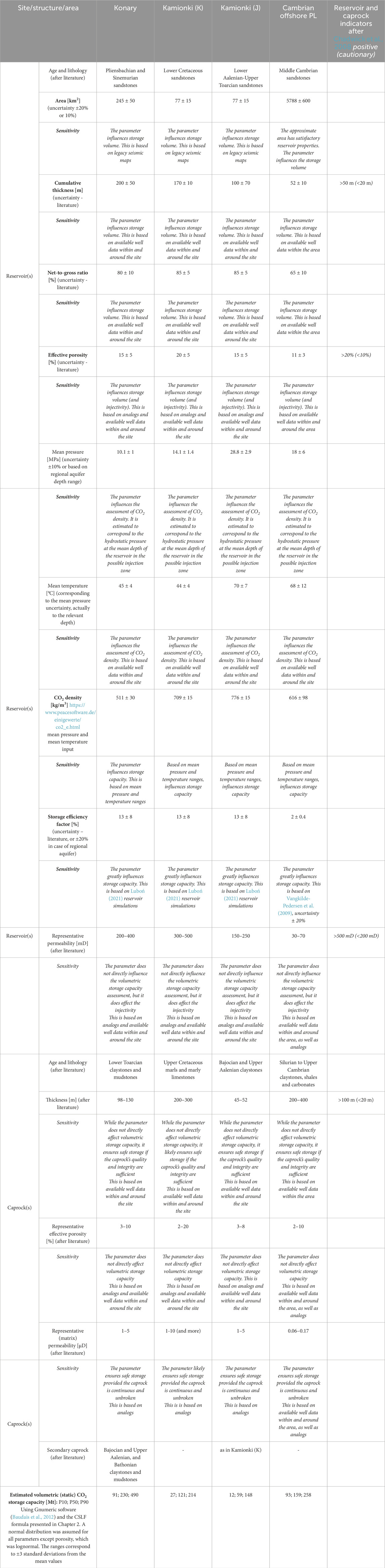
Table 2. Storage options, relevant parameters and sensitivities. The parameters indicated in bold have been used in the Monte Carlo simulation.
Recently, Luboń (2020), Luboń (2021) carried out injection simulations based on a simple geological model of the reservoir and data from one legacy well. The author calculated the single injection well storage capacity of the Pliensbachian reservoir at the summit of the structure (no deeper than 1000 m b.s.l.) to be between 10.2–15.5 Mt, depending on the assumed capillary pressure at the top of the reservoir and assumed faulting, and up to 49.9 Mt when the pressure parameter is not taken into consideration. The former values correspond to a storage efficiency factor range of 4.23%–6.44% (average 5%; Luboń, 2021), while the latter most likely corresponds to a factor of around 20.8%. These values were assumed as the uncertainty range in Table. Urych et al. (2022) conducted injection simulations in a Jurassic saline aquifer structure in northwestern Poland under similar geological conditions. These were hydraulic models based on clay content, porosity, and permeability data from boreholes within and near structures, similar to case studies of the national project (Wójcicki et al., 2014). However, rather than assessing the maximum safe dynamic storage capacity, they assumed the amount of CO2 injected per well and globally. Therefore, these simulations cannot be used to estimate the storage efficiency factor.
Caprock was not included in Luboń (2020), Luboń (2021) model, and its parameters are not included in the CSLF formula. However, they are critical to evaluating the structure. The available caprock data and information presented in Table 2 includes lithology, thickness, and representative permeability and porosity. Information on the thickness and lithology of the caprock within and around the structure comes from Feldman-Olszewska (2013) and Feldman-Olszewska et al. (2010), Feldman-Olszewska et al. (2012). So does porosity where also data from boreholes located further away, but in similar geological conditions were taken into account because of limited availability of such data within and around the structure. Due to the relatively low accuracy of available laboratory measurements of the permeability of rock samples from legacy wells within and around the structure (Feldman-Olszewska, 2013), data from analogs is assumed (Ladage, 2016; Smulski et al., 2013).
The inputs of the Monte Carlo simulations were based on similar assumptions as in Hjelm et al. (2020). The standard methodology of the open-source software (Baudais et al., 2012) and the standard CSLF formula (Vangkilde-Pedersen et al., 2009) were used. A simple sensitivity analysis is included in Table 2. It shows that uncertainty in the storage efficiency factor has the greatest influence on the calculated volumetric storage capacity. The simulations provided an assessment of the storage capacity (Table 2) corresponding to the emissions of the nearby industrial installations (total: 3.859 Mtpa) over a period of between 24 and 127 years (median: 60 years).
3.1.2 The Kamionki structure
The Kamionki structure comprises two reservoirs: the Lower Cretaceous sandstones (the primary) and the Lower Aalenian-Upper Toarcian (the backup) sandstones (Dziewińska et al., 2010; Feldman-Olszewska et al., 2012; Wójcicki et al., 2014; Figure 2E). The caprock is a thick sequence of Upper Cretaceous marls and marly limestones.
The structure was drilled by three legacy wells in 1972, 1973 and 1987 (see Figures 1, 2E) and explored by over twenty 2D seismic lines (in the 1970-90s) of varied quality. There are potential risks associated with trapping efficiency, closure and caprock integrity. The structure in Figure 2E appears to have a low amplitude. However, the section is close to three legacy wells located near the northeast tip of the structure (see Figure 1). As the Upper Cretaceous caprock is mostly composed of carbonate minerals, its sealing effect depends on the chemical reaction between dissolved CO2 and the rock. The entire sequence is around 1,000 m thick, but the section above the Lower Cretaceous reservoir, which is 200–300 m thick and has a higher clay content, is assumed to provide an adequate seal. This may be the case if the sequence makes a continuous or composite confining system, as discussed by Bump et al. (2023).
No (digital) geological models of the structure or injection simulations have been carried out. The reservoir and caprock parameters presented in Table 2 were assumed similarly as in the case of Konary structure (after Wójcicki et al., 2014; Geoportal CBDG boreholes, 2025a; Feldman-Olszewska, 2013; Feldman-Olszewska et al., 2010; Feldman-Olszewska et al., 2012; Dziewińska et al., 2010; Ladage, 2016; Smulski et al., 2013). The same uncertainty range for the storage efficiency factor was therefore assumed as in the Konary structure. Similarly, a simple sensitivity analysis is included in Table 2. It shows that uncertainty in the storage efficiency factor has the greatest influence on the calculated volumetric storage capacity.
Monte Carlo simulations provided an assessment of the storage capacity of the Lower Cretaceous reservoir (Table 2) corresponding to the emissions of the nearby industrial installations (total: 4.328 Mtpa) over a period ranging from 6 to 49 years (median: 28 years). The Lower Aalenian-Upper Toarcian reservoir, which is located much deeper, has a storage capacity of approximately half that of the previous one.
3.2 Offshore CO2 storage options
Approximately 120 km north of the Port of Gdańsk, there is an offshore Cambrian saline aquifer with likely satisfactory reservoir properties (Wójcicki and Pacześna, 2013; Gravaud et al., 2023), containing a couple of mature and relatively small hydrocarbon fields in the north-eastern part of the Polish sector of the Baltic Sea (see Figure 1). The aquifer is part of the mid-Baltic Dalders monocline, which extends from the Swedish to the Latvian sector. According to the international Bastor 2 project, the Dalders monocline could have a substantial volumetric storage capacity of up to 1.9 Gt (Nilsson, 2014; Vernon et al., 2013). However, it should be noted that this assessment may be overestimated if taking into consideration relatively low porosities and permeabilities of the relevant formations in Polish and adjacent Swedish sector of the Baltic Sea (Semyrka et al., 2010; Mortensen and Sopher, 2021). It is probable that the storage capacity of the Polish part will be inadequate to accommodate the emissions of all 16 selected emitters in the region. However, it may be sufficient for five of the northernmost emitters (Table 1; Figure 1; Wójcicki, 2025).
Should the regional Cambrian offshore aquifer in the Polish sector of the Baltic Sea be utilised as the storage site, it will be necessary to develop the necessary offshore infrastructure there, preferably integrated with the CO2 terminal in the Port of Gdańsk. The CO2 captured by the northernmost emitters could be transported to the prospective offshore aquifer in several ways. It could be transported by rail or by barge along the Vistula River, or it could be transported onshore via new pipelines to the future CO2 terminal in the Port of Gdańsk (Table 1). The transportation of liquefied CO2 from the Port of Gdańsk terminal to the offshore storage site under the Baltic Sea could be facilitated by ship or new undersea pipeline.
The reservoir rock of the aquifer is composed of Middle Cambrian sandstones, which are of mediocre to average porosity and permeability (Table 2). The reservoir is covered by a caprock made of a thick sequence of Upper Cambrian to Silurian claystones, shales and carbonates. The storage complex, which comprises the reservoir and the caprock, has been thoroughly explored in areas where hydrocarbon fields have been discovered and developed. However, little of this data has been published. The offshore Middle Cambrian saline aquifer is characterised in Table 2 using data and information from the following sources: Mortensen and Sopher (2021); Nilsson (2014); Semyrka et al. (2010); Vernon et al. (2013); and Wójcicki and Pacześna (2013). The area of the regional aquifer in the Polish sector that has satisfactory porosity and permeability is considered. The parameters of its Upper Cambrian–Silurian caprock are estimated using data from the following sources: Kuberska et al. (2021); Podhalańska et al. (2020); Poprawa (2020); and Schulz et al. (2021). It should be noted that, in the case of caprock permeability, data from analogs is assumed (Poprawa, 2020; Schulz et al., 2021). A simple sensitivity analysis is included.
According to the recently published results of CO2 injection simulations into the aquifer (Wojnicki et al., 2023), its dynamic capacity is approximately 150 Mt. Monte Carlo simulations provided a similar assessment of the volumetric storage capacity of the Middle Cambrian reservoir (Table 2) corresponding to the emissions of the five northernmost industrial installations (total: 6.61 Mtpa) over a period of between 14 and 39 years (median: 24 years).
4 Discussion
There are many challenges to the development of the value chain, including regulatory, social, financial and technical issues.
4.1 The regulatory issues
Regulatory challenges include national regulations on onshore storage and transport, which are currently being drafted, as well as international regulations on offshore storage.
4.1.1 Onshore CO2 storage
The regulations on onshore storage are to be announced soon for public consultations. The general legal framework of EU Directive 2009/31/EC on the geological storage of carbon dioxide (EUR-Lex, 2018) was adopted in Poland in 2013 and updated in 2023 as an amendment to the Geological and Mining Law (Galos, 2024). However, the law states that an ordinance issued by the permitting authority (i.e., the Ministry of Climate and the Environment) should determine the areas in which underground carbon dioxide storage complexes can be located. This means areas where potential CO2 storage sites can be explored and characterised, and where storage permits can be applied for. The ordinance, issued in 2014 (The Ordinance, 2014), does not determine any onshore areas, only one offshore area. The permitting authority has recently completed an amendment to the ordinance including onshore areas, which is to be announced for public consultation soon. After these regulations are adopted, the exploration and characterisation of potential storage sites can begin. Then, applications for storage permits can be submitted (Galos, 2024). An application for a storage permit should include documentation on the characterisation and assessment of the potential storage complex and the surrounding area, as well as the monitoring plans. Polish regulations on these issues are consistent with Annexes I and II of EU Directive 2009/31/EC (EUR-Lex, 2018; Galos, 2024). The application also requires the full environmental impact assessment procedure, which may be the key hurdle.
4.1.2 Offshore CO2 storage and the Helsinki Convention
Current national regulations permit the storage of CO2 in the relevant part of the Baltic Sea (The Ordinance, 2014).
However, Article 11 of the Helsinki Convention recommends banning CO2 storage under the Baltic Sea. CO2 storage is classified as “dumping” under the 2014 Helsinki Convention (The Helsinki Convention, 2014), i.e., “the deliberate disposal at sea or into the seabed of waste or other matter from ships, other man-made structures at sea or aircraft,” which is forbidden under Article 11. However, Article 11 already includes an exception for dumping. This issue could therefore be resolved through amending the article to create a new exception, as recommended by the relevant working groups of the Baltic Marine Environment Protection Commission (HELCOM) and subject to agreement by the relevant governments (Wammer Østgaard, 2024). The Call for tender: legal analysis of CCS in accordance with the Helsinki Convention was announced in September 2025 for this purpose (HELCOM, 2025). In parallel, the analysis of environmental and cumulative impacts and risks of Carbon Capture and Storage (CCS) in the Baltic Sea context is being conducted by the relevant working group (information from the author’s personal communication with the national ministry). Both analyses are to be presented to the relevant government bodies of the Baltic Sea countries for decision by mid-2026.
4.2 Potential social acceptance barriers for onshore storage
The next important issue is therefore the acceptance of large-scale onshore underground storage by local communities, given the current lack of knowledge about carbon capture and storage (CCS) technology and the potential fear surrounding it. Over a decade ago, a large-scale CCS project involving the utilisation of an onshore saline aquifer structure, as well as a public awareness campaign, was developed in Poland (Bełchatów). However, it was subsequently cancelled, as were several other similar European projects at the time (ECA, 2018). In the EU research project SiteChar (Kaiser et al., 2013; Brunsting et al., 2015), local communities and authorities in areas where CO2 storage in depleted gas fields is being considered were approached, interviewed, and informed about CCS technologies. The feedback was generally positive. In the research project Agastor (Wojakowski et al., 2024; Wojakowski et al., 2022) in area in NW Poland where CO2 and natural gas storage in saline aquifer structures is being considered local communities and authorities were approached. The feedback was mixed. While negative attitudes were correlated with lack of knowledge about the technology, acceptance may increase if the benefits to the community are emphasized. A nationwide survey presented in a report by the NGO WiseEuropa (Giers, 2024) indicates that the general population has a low level of knowledge about CO2 storage and that misinformation is prevalent in public opinion.
Therefore, the government, research institutions, and NGOs must be involved in disseminating knowledge about this topic again. Such an information and communication campaign must address several barriers (Giers, 2024). These include the relative lack of public knowledge about CO2 storage and the visible benefits it could bring to local communities where it is developed. The well-known NIMBY (Not In My Back Yard) phenomenon is important and can be partly explained by misinformation in the mainstream and social media, or by honest information that is too technical and a low level of trust in state institutions and big industry. Another barrier is the lack of any large-scale CO2 injection installations in operation in Poland. Currently, there is only one small-scale acid gas injection installation in a depleted gas field (Lubaś et al., 2020). There is a discrepancy between the high level of support for capturing CO2 and the low level of support for storing it (except in areas where hydrocarbons are produced).
4.3 Financial issues
The ECO2CEE Project of Common Interest, which is the seed part of the value chain, entails transporting carbon dioxide from two emitters (the Orlen Płock refinery and the Holcim cement plant) to the terminal in the Port of Gdańsk by rail until 2030. This is then followed by sea transport to storage sites beneath the North Sea (Orlen, 2024). The project is applying for European Union funding dedicated to infrastructure projects (European Commission, 2023) and must prevail in the competitive process. Construction of the industrial-scale capture unit at the Holcim cement plant is underway as part of the Go4ECOPlanet project. The project has received co-financing from the EU Innovation Fund for the full-chain solution (European Commission, 2022).
Following a review of potential locations for extending the ECO2CEE PCI in Poland beyond 2030, it was proposed that emitters located between the Port of Gdańsk terminal and the two initial emitters could be considered. At the same time, it is proposed that the original PCI concept be supplemented and enhanced with additional transport and local storage options. It is recommended that new pipeline construction be prioritised as a more long-term solution, with the understanding that this may be more cost-effective than other options such as rail, barge or ship transport. According to Nooraiepour et al. (2025), the operational costs of transporting CO2 by ship to the North Sea might be up to three times higher than by onshore pipeline (i.e. 30 vs 10 € per tonne).
4.4 Technical issues
One of the major risks to the further development of the value chain relates to the suitability of local storage options, a topic that this paper focuses on. Unlike hydrocarbon fields, the issue with saline aquifer structures is that the available legacy data is often insufficient or of poor quality for making investment decisions regarding the development of storage sites. Data on reservoir parameters is sparse and well-logging data calibrated with laboratory data is rarely available. There is usually even less data available on caprocks. Therefore, this study also used data on structures and formations in similar geological conditions - i.e., the same or equivalent formation and depositional environment, depth range, and diagenesis stage - to estimate the values and uncertainty ranges of the parameters in question. As shown in the case of one of the analysed structures, the quality of legacy seismic data may be insufficient for reliable assessment of caprock integrity.
Though these structures appear adequate for local storage in the value chain, according to this study based on limited and not always reliable data, their suitability, storage complex integrity, and storage capacity must be proven through exploration and site characterisation campaigns. This must be done using new models and injection simulations with new and legacy data that has been reprocessed and reinterpreted where necessary. Due to stakeholders’ particular concern about the long-term integrity of the seal, this issue must be addressed in light of current global developments in this field. As highlighted in the IEAGHG (2024) report, the geomechanical characterisation of the storage complex should be conducted using well logging and laboratory analyses, as well as modelling of the geochemical processes related to CO2-brine-rock interactions during and after injection. Ideally, coupled hydraulic, mechanical and chemical modelling should be used to evaluate the long-term integrity of the seal (IEAGHG, 2024). This generally aligns with the modelling requirements for the dynamic behaviour of CO2 storage, as set out in Annex 1 of the EU Directive 2009/31/EC on the geological storage of carbon dioxide (EUR-Lex, 2018) and included in the relevant Polish legislation (Galos, 2024).
It should be noted that the scope of this study includes the harmonisation and validation of different data from the literature on the considered storage sites in saline aquifers, including previous domestic and European projects in this area. Table 3 presents the most important risks and knowledge gaps related to the evaluation of these sites and should be addressed at the appraisal stage. The results of this stage, which integrates new seismic surveys and boreholes with legacy data, will confirm or refute their suitability. If the results are positive, the next step is site characterisation, which, together with previously collected data, will provide the information necessary for applying for a storage permit.

Table 3. Key risks and knowledge gaps pertaining to the evaluation of the considered storage options (based on Veloso, 2021).
4.5 The impact of these challenges on the feasibility of the value chain
The lack of onshore storage regulations in Poland is having a critical impact on the development of the value chain. The same applies to the Helsinki Convention’s ban on offshore storage under the Baltic Sea. Exploration and characterisation of the potential onshore storage sites cannot begin until the relevant regulations have been implemented. Offshore storage permits cannot be granted until the ban on storage underneath the Baltic Sea is lifted. At this moment, the only feasible option is storage underneath the North Sea, provided the CO2 terminal in Gdańsk is built.
Potential social acceptance barriers for onshore storage could not only prevent the granting of storage permits, but also the exploration and characterisation of potential storage sites. In order to increase public awareness, the government, research institutions and NGOs must collaborate on an information and communication campaign to address concerns related to CO2 onshore storage among the general population and local communities. This has to be done before field works begin and storage permits are applied for. Otherwise, gaining social acceptance for onshore CO2 storage could be problematic.
In terms of financial issues, it is important that the initial phase of the value chain, which includes the construction of two first industrial-scale capture installations (at the cement plant and the refinery) and CO2 import and export terminal, relies on financial support from European Union programmes. The appraisal and characterisation of potential storage sites is not as expensive as the above-listed capital expenditures and is the responsibility of the interested stakeholders, who may also apply for EU funding. Further development of the value chain would require state aid. This includes the addition of capture units in other industrial installations and transport infrastructure, such as pipeline networks and hubs, as well as the possible enlargement of storage infrastructure. The relevant national strategies and legal framework are not yet ready.
To prove the suitability and safety of using local storage, site appraisal and characterisation are necessary. This applies both to potential onshore and offshore storage sites. Safe storage scenarios seem to be feasible at onshore sites, which enclose multi-layered reservoir and caprock sequences. However, the subsequent caprock evaluation and storage complex models may restrict the storage capacity that can be safely utilised. In such a case, additional structures located near the ones under consideration must be evaluated, appraised, characterised and developed. Offshore storage involves a regional saline aquifer, which is better explored than onshore structures, albeit unevenly. However, the storage capacity that can be safely utilised may be restricted by the caprock evaluation and storage complex modelling following the site characterisation.
5 Summary
In the CCUS ZEN project, one of the value chains under consideration included emission sources located in the region of northern Poland. The value chain is closely linked to the scope of the ECO2CEE Project of Common Interest (PCI) on CO2 import-export terminal in the Port of Gdańsk. In the initial phase of the ECO2CEE project, the focus is on integrating railway transportation for CO2 captured in two installations within the examined value chain. The carbon dioxide, once delivered to the terminal, will be transported by ship and stored beneath the North Sea. However, there is significant local storage potential within the region and its immediate vicinity, both onshore and offshore. It is therefore proposed that the original concept of the PCI be supplemented with additional CO2 emitters of the value chain and enhanced by the introduction of additional transport and local storage options. The volumetric (static) capacities of the storage sites in the value chain are calculated taking into consideration available data on CO2 injection simulations and caprock quality. Due to the limited legacy data available, information for structures in analogous geological conditions is also utilised to estimate the values and uncertainty ranges of the parameters in question. Although the estimated volumetric capacities seem adequate for the potential demand of the value chain, they should be verified using new field data, new geological models and injection simulations. The regulatory, social, financial and technical challenges, and their impact on the feasibility of the value chain, are discussed.
6 Conclusion
Utilising the local CO2 storage options has the potential to expand the value chain of the ECO2CEE Project of Common Interest in northern Poland beyond its original scope. In conjunction with the proposed transport infrastructure, onshore and/or offshore storage options in the region have the potential to supplement and enhance the original concept of the PCI, which is based on the CO2 import-export terminal in the Port of Gdańsk.
The implementation of this solution is contingent on the completion of several key processes. Firstly, the adoption of national regulations on onshore CO2 storage and transport is essential. Secondly, any potential barriers to the social acceptance of onshore CO2 storage should be overcome. Thirdly, the issue of the ban on CO2 storage under the Baltic Sea, as set out in Article 11 of the Helsinki Convention, needs to be resolved. Last but not least, funding for the initial phase and further development must be secured.
Although there is no published government-backed CCS roadmap for Poland yet, work on this is in progress. However, a couple of published documents address this issue, and their conclusions are consistent with the findings of this study on the use of CCS technologies for the decarbonisation of industrial installations and the utilisation of local CO2 storage potential. Firstly, the policy and financing roadmap proposed by the NGO WiseEuropa (Laskowski and Giers, 2024) states that heavy industry sectors in Poland, such as cement, chemicals and steel, must use CCS technologies in order to fulfil the EU’s decarbonisation goals and remain competitive in the market over the next few decades. They recommend developing long-term decarbonisation strategies and policies, facilitating state aid and completing the regulatory framework, as well as eliminating barriers and implementing financial mechanisms to support the deployment of CCS. Secondly, in its factsheet on prospects of CCS development in Poland, the Clean Energy Task Force (Busch et al., 2024) emphasises the need to utilise local CO2 potential to decarbonise key industrial sectors. The rationale is that transporting all captured CO2 to the North Sea for storage would make Polish industries less competitive due to high transport costs and the geographical distribution of emitters. The CATF also recommends using Polish onshore CO2 storage potential to fulfil the needs of neighbouring countries.
As this paper does not focus on the feasibility of developing the value chain, but rather on the possibilities of utilising local CO2 storage potential, a general roadmap for achieving this goal can be proposed. It should be noted that such activities do not constitute a research project, but could be the responsibility of interested stakeholders. Let us assume that the onshore storage regulations in Poland are adopted by the mid-2026 and that they cover the area in question. In this case, the stakeholder can prepare and submit to the permitting authority a geological work plan for seismic surveys (2D, then 3D) and appraisal well(s) drilling at the potential storage site (Galos, 2024). An environmental impact report approved by the relevant authority may be required, particularly if drilling is planned in a protected area. The drilling operation plan must be approved by the relevant mining authority. Before the work plan can be finalised, a detailed inventory of legacy seismic and well logging data, laboratory analyses and drilling cores must be compiled. This will inform the planning of new surveys, drilling and laboratory experiments on new and legacy core samples, as well as the reprocessing of legacy seismic data. It could take a couple of months to complete the work plan, and a similar amount of time could be required for approval by the permitting authority. Therefore, if no environmental impact report is required, fieldwork could begin by the end of 2026 at the earliest. In parallel, the reprocessing of selected legacy seismic lines should commence, as should laboratory analyses of the petrophysical and geomechanical parameters of the legacy reservoir and caprock samples. A geological-parametric model of the storage complex will then be constructed using new and legacy data, and any other relevant information. The site characterisation could take a couple of years (till 2028–2029). This includes dynamic modelling in the storage complex. Such characterisation is required when applying for the storage permit, along with monitoring plans and a full environmental impact assessment. The latter could also take a couple of years. According to the current Polish legal framework (Galos, 2024), pilot CO2 injection is permitted during the site development phase, once a storage permit has been granted. Assuming the ban on CO2 storage under the Baltic Sea is resolved by mid-2026, a similar timeline and process could be adopted for offshore storage.
This study builds on the findings of the CCUS ZEN project by focusing on the local storage options of one of the value chains considered in that study (Lothe et al., 2025). The CCUS project used developments in CCUS around the relatively mature North Sea region as a model for developing new CCUS value chains in currently underdeveloped areas such as the Baltic Sea region. This study shows that deploying and developing such a relatively immature value chain requires integrating technical and non-technical aspects, including legal, social and policy frameworks. It focuses specifically on the use of local CO2 storage potential as an alternative and supplementary measure to shipping, potentially forming part of future regional and pan-European CO2 storage and CCS infrastructure.
Data availability statement
The original contributions presented in the study are included in the article/supplementary material, further inquiries can be directed to the corresponding author.
Author contributions
AW: Writing – original draft, Writing – review and editing.
Funding
The author(s) declare that financial support was received for the research and/or publication of this article. The research has been supported by the CCUS ZEN project of the Horizon Europe programme (grant. no. 101075693, coordinator SINTEF, Norway) financed by the CINEA.
Conflict of interest
The author declares that the research was conducted in the absence of any commercial or financial relationships that could be construed as a potential conflict of interest.
Generative AI statement
The author(s) declare that no Generative AI was used in the creation of this manuscript.
Any alternative text (alt text) provided alongside figures in this article has been generated by Frontiers with the support of artificial intelligence and reasonable efforts have been made to ensure accuracy, including review by the authors wherever possible. If you identify any issues, please contact us.
Publisher’s note
All claims expressed in this article are solely those of the authors and do not necessarily represent those of their affiliated organizations, or those of the publisher, the editors and the reviewers. Any product that may be evaluated in this article, or claim that may be made by its manufacturer, is not guaranteed or endorsed by the publisher.
References
Akhurst, M., Kirk, K., Neele, F., Grimstad, A., Bentham, M., and Bergmo, P. (2021). Storage readiness levels: communicating the maturity of site technical understanding, permitting and planning needed for storage operations using CO2. Int. J. Greenh. Gas. Control 110, 103402. doi:10.1016/j.ijggc.2021.103402
Al Maqbali, Q., Hussain, S., Mask, G., and Wu, X. (2023). “Numerical simulation of in-situ CO2 mineralization in mafic basaltic formations in southwest Oklahoma,” in Paper presented at the SPE Oklahoma City oil and gas symposium, Oklahoma City, Oklahoma, USA, April 2023. doi:10.2118/213084-MS
Alsayah, A., and Rigby, S. P. (2023). Coupled multiphase flow, geochemical, and geomechanical modelling of the impact of shale interlayers on CO2 migration. Geoenergy Sci. Eng. 229, 212101. doi:10.1016/j.geoen.2025.214011
Anthonsen, K. L., Aagaard, P., Bergmo, P. E., Gislason, S. R., Lothe, A. E., Mortensen, G. M., et al. (2014). Characterisation and selection of the Most prospective CO2 storage sites in the Nordic Region. Energy Procedia 63, 4884–4896. doi:10.1016/j.egypro.2014.11.519
Bachu, S. (2015). Review of CO2 storage efficiency in deep saline aquifers. Int. J. Greenh. Gas Control 40, 188–202. doi:10.1016/j.ijggc.2015.01.007
Baudais, E., Breit, K., Canty, T., Custer, A., Dassen, R., Goldberg, R., et al. (2012). The gnumeric manual, version 1.12 – advanced analysis, GNOME documentation project. Available online at: https://help.gnome.org/users/gnumeric/stable/sect-advanced-analysis-simulation.html.en.
Brunsting, S., Mastop, J., Kaiser, M., Zimmer, R., Shackley, S., Mabon, L., et al. (2015). CCS acceptability: social site characterization and advancing awareness at prospective storage sites in Poland and Scotland. Oil and Gas Sci. Technol. – Rev. IFP Energies nouvelles 70 (4), 767–784. doi:10.2516/ogst/2014024
Bump, A. P., Bakhshian, S., Ni, H., Hovorka, S. D., Olariu, M. I., Dunlap, D., et al. (2023). Composite confining systems: rethinking geologic seals for permanent CO2 sequestration. Int. J. Greenh. Gas Control 126, 103908. doi:10.1016/j.ijggc.2023.103908
Busch, A., Alles, S., Gensterblum, Y., Prinz, D., Dewhurst, D. N., and Raven, CATF (2024). Carbon capture and storage in Poland. Harnessing Poland’s potential for carbon capture and storage. Clean. Air Task Force Factsheet. Available online at: https://cdn.catf.us/wp-content/uploads/2024/04/26092017/ccs-poland-fact-sheet.pdf.
CCUS ZEN (2025). Accelerating the deployment of CCUS throughout Europe. Available online at: https://ccuszen.eu/.
Chadwick, R. A., Arts, R., Bernstone, C., May, F., Thibeau, S., and Zweigel, P. (2008). Best practice for the storage of CO2 in saline aquifers, 14. Keyworth, Nottingham: British Geological Survey Occasional Publication No.
Christensen, N. P., and Larsen, M. (2004). Assessing the European potential for geological storage of CO2: the GESTCO project. GEUS Bull. 4, 13–16. doi:10.34194/geusb.v4.4770
CSLF (2019). Improved pore space utilisation: current status of techniques. Available online at: https://fossil.energy.gov/archives/cslf/sites/default/files/documents/Task-Force-on-Improved-Pore-Space-Utilisation_Final-Report.pdf.
CSLF (2021). Carbon sequestration technology roadmap, 1–69. Available online at: https://fossil.energy.gov/archives/cslf/sites/default/files/documents/CSLF_Tech_Roadmap_2021_final.pdf.
Danish Energy Agency (2024). Technology data – carbon capture, transport and storage. Available online at: https://ens.dk/node/3446.
Dean, M., Snippe, J., Busch, A., Fink, R., Hursyt, S., Lidstone, A., et al. (2020). Final report of the DETECT project. Available online at: https://geoenergy.hw.ac.uk/wp-content/uploads/DETECT-Project-Final-Report-for-ACT-website-24.02.2021.pdf.
J. Dembowska, and S. Marek (1985). Gostynin IG-1/1a, Gostynin IG-3, Gostynin IG-4, Żychlin IG-3 (Warszawa: Wydawnictwa Geologiczne), 60, 302. PGI-NRI (the borehole report in Polish).
Dziewińska, L., Marek, S., Tarkowski, R., and Uliasz-Misiak, B. (2010). Potential geological structures to CO2 storage in the Mesozoic Polish Lowlands (characteristics and ranking). Stud. Rozpr. i Monogr. IGSMiE PAN 164, 1–138. Available online at: https://www.researchgate.net/publication/280774308_Potencjalne_struktury_geologiczne_do_skladowania_CO2_w_utworach_mezozoiku_Nizu_Polskiego_charakterystyka_oraz_ranking.
ECA (2018). Demonstrating carbon capture and storage and innovative renewables at commercial scale in the EU: intended progress not achieved in the past decade. Special report. Available online at: https://www.eca.europa.eu/Lists/ECADocuments/SR18_24/SR_CCS_EN.pdf.
Espinoza, D. N., and Santamarina, J. C. (2017). CO2 breakthrough – caprock sealing efficiency and integrity for carbon geological storage. Int. J. Greenh. Gas Control 66, 218–229. doi:10.1016/j.ijggc.2017.09.019
EUR-Lex (2018). Directive 2009/31/EC of the European Parliament and of the Council of 23 April 2009 on the geological storage of carbon dioxide and amending Council directive 85/337/EEC, European Parliament and Council directives 2000/60/EC, 2001/80/EC, 2004/35/EC, 2006/12/EC, 2008/1/EC and regulation (EC) no 1013/2006 (text with EEA relevance). Official Journal of the European Union L 140/114, 5/6/2009, current consolidated version: 24/12/2018.
European Commission (2022). Innovation Fund Projects. Available online at: https://climate.ec.europa.eu/eu-action/eu-funding-climate-action/innovation-fund/innovation-fund-projects_en.
European Commission (2023). The Union list of Projects of Common Interest and Projects of Mutual Interest. Available online at: https://energy.ec.europa.eu/system/files/2023-11/Annex%20PCI%20PMI%20list.pdf.
European Commission (2025). Union registry. Available online at: https://climate.ec.europa.eu/eu-action/eu-emissions-trading-system-eu-ets/union-registry_en#a-single-eu-registry.
A. Feldman-Olszewska (2007). Ciechocinek IG 2. Profile głębokich otworów wiertniczych, 117, 133. Available online at: https://www.pgi.gov.pl/oferta-inst/wydawnictwa/serie-wydawnicze/profile-otworow-pig/6125-zeszyt-117-2007-a8211-ciechocinek-ig-2.html.
A. Feldman-Olszewska (2008). Brześć Kujawski IG 1, IG 2, IG 3. Profile głębokich otworów wiertniczych, 125, 320. Available online at: https://www.pgi.gov.pl/oferta-inst/wydawnictwa/serie-wydawnicze/profile-otworow-pig/6117-zeszyt-125-2008-a8211-brzepujawski-ig-1-ig-2-ig-3.html.
Feldman-Olszewska, A. (2013). “Korelacje międzyotworowe – Jura w rejonie Kujaw (crosswell correlations – Jurassic period in the Kuyavia region),” in Assessment of formations and structures suitable for safe CO2 storage (in Poland) including the monitoring plans. The project task report 1. Editors A. Wójcicki, S. Nagy, J. Lubaś, J. Chećko, and R. Tarkowski, 282–296. Available online at: https://skladowanie.pgi.gov.pl/twiki/pub/CO2/WynikiPrac/I-3.pdf.
Feldman-Olszewska, A., Adamczak, T., and Szewczyk, J. (2010). Geological characterization of the reservoir and seal levels in the Zaosie and Jeżów structures as a candidate site for CO2 storage on the basis of the data from deep boreholes. Biul. Państwowego Inst. Geol. 439 (1), 17–28. Available online at: https://geojournals.pgi.gov.pl/bp/article/view/28847.
Feldman-Olszewska, A., Adamczak-Biały, T., and Becker, A. (2012). Characterization of the Jurassic and Triassic reservoirs and seals from north Mazovia as a candidate site for CO2-storage based on data from deep boreholes. Biul. Państwowego Inst. Geol. 448 (1), 27–46. Available online at: https://geojournals.pgi.gov.pl/bp/article/view/29091.
Galos, K. (2024). Prawo geologiczne i górnicze - zmiana ustawy: aspekty prawne podziemnego składowania dwutlenku węgla (the geological and mining law – the amendment: legal aspects of underground storage of carbon dioxide). Pap. Present. at CCUS.pl Conf. Warsaw, Pol. 1-2 Febr., 2024. Available online at: https://ccus.pl/uthistag/2024/02/0102_MKiS_KG.pdf.
GCCSI (2024). Global status of CCS 2024. Collab. Net Zero Future. Available online at: https://www.globalccsinstitute.com/wp-content/uploads/2024/10/Global-Status-Report-6-November.pdf.
Geoportal CBDG Boreholes (2025a). Konary IG-1. Available online at: https://otworywiertnicze.pgi.gov.pl/details/23255 (Accessed September 18, 2025).
Geoportal CBDG Boreholes (2025b). Kamionki IG-3. Available online at: https://otworywiertnicze.pgi.gov.pl/details/13143 (Accessed September 18, 2025).
Giers, M. (2024). Akceptacja społeczna technologii CCUS w polsce (social acceptance of CCUS technologies in Poland). WiseEuropa, 34pp. Rep. CCUS.pl Res. Proj. (in Polish with an English summary). Available online at: https://wise-europa.eu/wp-content/uploads/2024/11/Akceptacja-spoleczna-technologii-CCUS-w-Polsce.pdf.
Gilmore, K. A., Sahu, C. K., Benham, G. P., Neufeld, J. A., and Bickle, M. J. (2022). Leakage dynamics of fault zones: experimental and analytical study with application to CO2 storage. Journal of Fluid Mechanics 931, A31. doi:10.1017/jfm.2021.970
Goodman, A., Hakala, A., Bromhal, G., Deel, D., Rodosta, T., Frailey, S., et al. (2011). U.S. DOE methodology for the development of geologic storage potential for carbon dioxide at the national and regional scale. International Journal of Greenhouse Gas Control 5 (4), 952–965. doi:10.1016/j.ijggc.2011.03.010
W. Górecki (2006). Atlas of geothermal resources of Mesozoic formations in the Polish Lowlands (AGH University of Science and Technology in Krakow. Ministry of Environment). Available online at: https://kse.agh.edu.pl/uploaded/AGH-Atlas_Geotermalny_Mezozoiku-2006.pdf.
Gravaud, I., Shogenova, A., Shogenov, K., Sousa, L.-H., Wójcicki, A., Lothe, A. E., et al. (2023). D1.2 identification of promising CCUS value chains in the two ZEN regions for further analyses in WP3. E. U. Horizon Europe CCUS ZEN. Available online at: https://zenodo.org/records/14393008.
HELCOM (2025). Call for tender: legal analysis of CCS in accordance with the Helsinki Convention. Available online at: https://helcom.fi/about-us/vacancies/call-for-tender-legal-analysis-of-ccs-in-accordance-with-the-helsinki-convention/.
Hesselbo, S., and Pieńkowski, G.(2011). Stepwise atmospheric carbon-isotope excursion during the Toarcian Oceanic anoxic event (early Jurassic, Polish Basin). Earth and Planetary Science Letters 301, 365–372. doi:10.1016/j.epsl.2010.11.021
Hjelm, L., Lyng Anthonsen, K., Dideriksen, K., Møller Nielsen, C., Nielsen, L. H., and Mathiesen, A. (2020). Capture, storage and use of CO2 (CCUS) evaluation of the CO2 storage potential in Denmark (GEUS report). Available online at: https://www.geus.dk/Media/637847556390112103/Evaluation%20of%20the%20CO2%20storage%20potential%20in%20Denmark_2020_46.pdf.
Ho, A., Giannopoulos, D., Pilorge, H., and Psarras, P. (2024). Opportunities for rail in the transport of carbon dioxide in the United States. Front. Energy Res., Sec. Carbon Capture, Utilization and Storage 11, 1343085–2023. doi:10.3389/fenrg.2023.1343085
Hussain, S., Wu, X., and Ben, S. (2021). “Numerical mechanistic study of in-situ CO2 EOR – Kinetics and recovery performance analysis,” in Paper presented at the SPE annual technical conference and exhibition, Dubai, UAE, September 2021. doi:10.2118/206292-MS
Hussain, S., Ahmed, Z., Zakir, M. M., Iqbal, M., Wu, J. J., and Wu, X. (2023). “Role of temperature on the performance of in-situ CO2 EOR,” in Paper presented at the SPE/PAPG Pakistan section annual technical symposium and exhibition, islamabad, Pakistan. doi:10.2118/219495-MS
IEAGHG (2025). “Reviewing the implications of unlikely but potential CO2 migration to the surface or shallow subsurface”. doi:10.62849/2025-01
Kaiser, M., Zimmer, R., Brunsting, S., Mastop, J., and Pol, M. (2013). Development of CCS projects in Poland. How to communicate with the local public?. Energy Procedia 51, 267–273. doi:10.1016/j.egypro.2014.07.031
Kijewska, S. (2024). “Interpretacja danych sejsmicznych, struktura konary (interpretation of seismic data, konary structure),” in Ocena stopnia szczelności oraz charakterystyka geologiczna i geomechaniczna wybranych struktur Na potrzeby podziemnego magazynowania i składowania substancji na obszarze Niżu polskiego (assessment of impermeability and geological and geomechanical characteristics of selected structures for the purposes of underground storage and disposal of substances in the Polish lowlands). PGI-NRI. Domestic project report (in Polish), chapter 7.1.2. Editors A. Wójcicki, and M. Adamuszek, 322–331. Available online at: https://skladowanie.pgi.gov.pl/twiki/pub/Magazyny/WebHome/Raport_koncowy_Tom_I.pdf.
Kivi, I. R., Makhnenko, R. Y., Oldenburg, C. M., Rutqvist, J., and Vilarrasa, V. (2022). Multi-layered systems for permanent geologic storage of CO2 at the gigatonne scale. Geophysical Research Letters 49 (24), e2022GL100443. doi:10.1029/2022GL100443
Klimkowski, Ł., Nagy, S., Papiernik, B., Orlic, B., and Kempka, T. (2015). Numerical simulations of enhanced gas recovery at the załęcze gas field in Poland confirm high CO2 storage capacity and mechanical integrity. Oil and Gas Science and Technology – Rev. IFP Energies nouvelles. 70, 655–680. doi:10.2516/ogst/2015012
Kozłowska, A., and Kuberska, M. (2014). Diageneza a porowatość piaskowców jury dolnej na Niżu Polskim. Biuletyn Państwowego Instytutu Geologicznego 458, 39–60. doi:10.5604/08676143.1113229
Kuberska, M., Sikorska-Jaworowska, M., Kozłowska, A., and Podhalańska, T. (2021). Petrographic characteristics of the Ordovician and Silurian deposits in the Baltic Basin (N Poland) and their relevance for unconventional hydrocarbon accumulations. Geological Quarterly 65 (3), 44. doi:10.7306/gq.1613
Labus, K., Tarkowski, R., and Wdowin, M. (2014). Modeling gas–rock–water interactions in carbon dioxide storage capacity assessment: a case study of Jurassic sandstones in Poland. Int. J. Environ. Sci. Technol. 12, 2493–2502. doi:10.1007/s13762-014-0652-6
Ladage, S. (2016). Schieferöl und Schiefergas in Deutschland Potenziale und Umweltaspakte. BGR report. Available online at: https://www.bgr.bund.de/DE/Themen/Rohstoffe/Downloads/Downloads_EN/Abschlussbericht_13MB_Schieferoelgaspotenzial_Deutschland_2016.pdf?__blob=publicationFile&v=1.
Laskowski, K., and Giers, M. (2024). Poland’s heavy industry decarbonisation, policy and financing roadmap. WiseEuropa. Available online at: https://wise-europa.eu/wp-content/uploads/2024/06/Poland_Roadmap-ENG-1.pdf.
Lothe, A. E., Bergmo, P. E. S., Emmel, B. U., and Mortensen, G. M. (2016). “CO2 storage capacity estimates for a Norwegian and a Swedish aquifer using different approaches - from theoretical volumes, basin modelling to reservoir models,” in Geologic carbon sequestration: understanding reservoir concepts. Editor T. N. Singh (Springer International Publishing), 98–117.
Lothe, A. E., Gravaud, I., Ringstad, C., Falck da Silva, E., Skagestad, R., Shogenova, A., et al. (2024). “A framework for regional high-level technical screening of promising CCUS value chains,” in 17th International Conference on Greenhouse Gas Control Technologies. Available online at: https://papers.ssrn.com/sol3/papers.cfm?abstract_id=5068864.
Lothe, A. E., Gravaud, I., Ringstad, C., Falck da Silva, E., Skagestad, R., Shogenova, A., et al. (2025). A framework for regional high-level technical screening of promising CCUS value chains. Front. Earth Sci. Sec. Georeservoirs 13-2025, 1641951. doi:10.3389/feart.2025.1641951
Lubaś, J., Szott, W., and Wójcicki, A. (2015). Wspomaganie wydobycia ropy naftowej i gazu ziemnego z polskich złóż z wykorzystaniem CO2 i jego równoczesną sekwestracją – enhanced oil and gas recovery from Poland’s hydrocarbon reservoirs by CO2 injection with simultaneous CO2 sequestration. Biuletyn Państwowego Instytutu Geologicznego 465, 45–46. doi:10.5604/08676143.120172
Lubaś, J., Szott, W., Lętkowski, P., Gołąbek, A., Miłek, K., Warnecki, M., et al. (2020). Long-term sequestration process in the Borzęcin structure – observation evidence of the injected acid gas migration and possible leakage. Prace Naukowe Inst. Nafty i Gazu 230.
Luboń, K. (2020). CO2 storage capacity of a deep aquifer depending on the injection well location and cap rock capillary pressure. Gospodarka Surowcami Mineralnymi – Mineral Resources Management 36 (2), 173–196. doi:10.24425/gsm.2020.132557
Luboń, K. (2021). Influence of injection well location on CO2 geological storage efficiency. Energies 14, 8604. doi:10.3390/en14248604
Michna, M., and Papiernik, B. (2012). Analiza elementów ryzyka geologicznego rejonu Suliszewo-Radęcin W kontekście składowania CO2 — analysis of geological risk elements in the Suliszewo-Radęcin area from the point of view of carbon dioxide storage. Biuletyn Państwowego Instytutu Geologicznego, nr 448, 81–86. Available online at: https://geojournals.pgi.gov.pl/bp/article/view/29095/20763.
Miecznik, M., Tyszer, M., Sowiżdżał, A., Pierzchała, K., Pająk, L., and Gładysz, P. (2025). Numerical modeling of potential CO2-Fed enhanced geothermal system (CO2-EGS) in the gorzów block, Poland. Energies 18 (18), 4825. doi:10.3390/en18184825
Mortensen, G., and Sopher, D. (2021). Geologisk lagring av koldioxid i sverige och i grannländer – status och utveckling (SGU report). Available online at: https://resource.sgu.se/dokument/publikation/rr/rr202104rapport/RR2104.pdf.
Nilsson, P. A. (2014). CCS in the Baltic Sea Region – Bastor 2 final summary report. Elforsk report 14, 50. Available online at: https://energiforskmedia.blob.core.windows.net/media/19832/ccs-in-the-baltic-sea-region-final-summary-report-elforskrapport-2014-50.pdf.
Nooraiepour, M., Dąbrowski, K., Masoudi, M., Kuczyński, S., Song, Z., Lothe, A. E., et al. (2025). Geological CO2 storage in Poland: review of sequestration potential, policy development, and socio-economic factors. EarthArXiv August, 2025. doi:10.31223/X5SB34
Orlen (2024). “ORLEN S.A. – implementing CCS through ECO2CEE project,” in Baltic Carbon Forum 2024. Available online at: https://baltic-carbon-forum.com/2024/wp-content/uploads/2024/10/00.01.pdf.
Pieńkowski, G. (2015). Geological storage of carbon dioxide (CCS) is safe – geological evidence. Przegląd Geologiczny 63, 48–54. Available online at: https://geojournals.pgi.gov.pl/pg/article/view/27522.
Pieńkowski, G., Schudack, M. E., Bosák, P., Enay, R., Feldman-Olszewska, A., Golonka, J., et al. (2008). “Jurassic,” in The geology of central Europe volume 2: Mesozoic and Cenozoic. Editor T. McCann (The Geological Society of London) (co-ordinators). doi:10.1144/CEV2P.2
Podhalańska, T., Feldman-Olszewska, A., Roszkowska-Remin, J., Janas, M., Pachytel, R., Głuszyński, A., et al. (2020). Prospective zones of unconventional hydrocarbon reservoirs in the Cambrian, Ordovician and Silurian shale formations of the East European craton marginal zone in Poland. Geological Quarterly 64 (2), 342–376. doi:10.7306/gq.1540
Poprawa, P. (2020). Lower Paleozoic oil and gas shale in the Baltic-Podlasie-Lublin Basin (Central and Eastern Europe) – a review. Geological Quarterly 64 (3), 515–566. doi:10.7306/gq.1542
Poulsen, N., Holloway, S., Neele, F., Smith, N. A., and Kirk, K. (2015). “CO2StoP final report, assessment of CO2 storage potential in Europe,” in European commission contract no ENER/C1/154-2011-SI2.611598. GEUS report 2014/56. Available online at: https://energy.ec.europa.eu/publications/assessment-co2-storage-potential-europe-co2stop_en.
Rackley, S. A., and Rackley, S. A. (2017). Carbon capture and storage. Elsevier. doi:10.1016/C2015-0-01587-8
Ringstad, C., Falck da Silva, E., Skagestad, R., Heyn, R., Biragnet, C., Frykman, P., et al. (2023). D1.1 High-level regional mapping of CO2 emission sources, utilization industry and infrastructure in the Baltic Sea and Mediterranean Sea regions. E. U. Horizon Europe CCUS ZEN. Available online at: https://zenodo.org/records/14392847.
Schulz, H.-M., Yang, S., Schovsbo, N. H., Rybacki, E., Ghanizadeh, A., Bernard, S., et al. (2021). The Furongian to Lower Ordovician alum shale formation in conventional and unconventional petroleum systems in the Baltic Basin – a review. Earth-Science Reviews 218, 103674. doi:10.1016/j.earscirev.2021.103674
Semyrka, G., Jarzyna, J., Pikulski, L., Kamierczuk, M., and Semyrka, R. (2010). Reservoir parameters of lithostratigraphic successions of the lower Paleozoic strata in the Polish part of the Baltic region based on laboratory studies and well logs. Geological Quarterly 54, 227–240. Available online at: https://gq.pgi.gov.pl/article/view/7570.
Śliwińska, A., Strugała-Wilczek, A., Krawczyk, P., Leśniak, A., Urych, T., Chećko, J., et al. (2022). Carbon capture utilisation and storage technology development in a region with high CO2 emissions and low storage potential – a case study of Upper Silesia in Poland. Energies 15 (12), 4495. doi:10.3390/en15124495
Smulski, R., Nagy, S., and Klimkowski, Ł. (2013). “Zagadnienia stanu technicznego i szczelności otworów - badania laboratoryjne skał o niskiej przepuszczalności, określenie ciśnienia progowego skał uszczelniających (laboratory testing of low-permeability rocks and determining the threshold pressure of sealing rocks),” in Assessment of formations and structures suitable for safe CO2 storage (in Poland) including the monitoring plans. The project task report 1. Editors A. Wójcicki, S. Nagy, J. Lubaś, J. Chećko, and R. Tarkowski, 135–148. Available online at: https://skladowanie.pgi.gov.pl/twiki/pub/CO2/WynikiPrac/I-7.pdf.
Soomro, A. N., Anioł, Ł., Kudasik, M., Dąbrowski, K., and Nagy, S. (2025). Comparative analysis of capillary threshold pressure measurement techniques: mercury intrusion porosimetry vs. innovative measuring tool for carbon storage. Frontiers in Energy Research (Sec. Carbon Capture, Utilization and Storage) 13, 1518424. doi:10.3389/fenrg.2025.1518424
Szott, W., and Miłek, K. (2021). Analysis of reservoir fluid migration in the process of CO2 sequestration in a partially depleted gas reservoir. Energies 14 (19), 6398. doi:10.3390/en14196398
Tarkowski, R., and Wdowin, M. (2011). Petrophysical and mineralogical research on the influence of CO2 injection on Mesozoic reservoir and caprocks from the Polish Lowlands. Oil Gas Sci. Technol. – Rev. IFP Energies nouvelles 66 (1), 137–150. doi:10.2516/ogst/2011005
Tarkowski, R., Uliasz-Misiak, B., and Królik, W. (2006). “Deep geological structures as sites to CO2 storage in Poland,” in Paper presented at the 8th International Conference on Greenhouse Gas Technologies (GHGT-8) trondheim, Norway, 19th–22nd June 2006.
Tarkowski, R., Uliasz-Misiak, B., and Wójcicki, A. (2009). GHGT-9 CO2 storage capacity of deep aquifers and hydrocarbon fields in Poland – EU GeoCapacity project results. Energy Procedia 1, 2671–2677. doi:10.1016/j.egypro.2009.02.035
Tarkowski, R., Wdowin, M., and Labus, K. (2011). Results of mineralogic-petrographical studies and numerical modeling of water-rock-CO2 system of the potential storage site within the Bełchatów area (Poland). Energy Procedia 4, 3450–3456. doi:10.1016/j.egypro.2011.02.270
The Helsinki Convention (2014). Convention on the protection of the marine environment of the Baltic Sea area. Available online at: https://helcom.fi/wp-content/uploads/2019/06/Helsinki-Convention_July-2014.pdf.
The Ordinance (2014). Ordinance of the Minister of the Environment of September 3, 2014 on areas where the location of an underground carbon dioxide storage complex is allowed. Available online at: https://dziennikustaw.gov.pl/D2014000127201.pdf.
Thompson, N., Andrews, J. S., Wu, L., and Meneguolo, R. (2022). Characterization of the in-situ stress on the Horda platform – a study from the Northern Lights Eos well. International Journal of Greenhouse Gas Control 114, 103580. doi:10.1016/j.ijggc.2022.103580
Urych, T., and Smoliński, A. (2019). Numerical modeling of CO2 migration in saline aquifers of selected areas in the Upper Silesian coal Basin in Poland. Energies 12, 3093. doi:10.3390/en12163093
Urych, T., Chećko, J., Magdziarczyk, M., and Smoliński, A. (2022). Numerical simulations of carbon dioxide storage in selected geological structures in north-western Poland. Front. Energy Res. 10, 827794. doi:10.3389/fenrg.2022.827794
van Bergen, F., Pagnier, H. J. M., van der Meer, L. G. H., van den Belt, F. J. G., Winthaegen, P. L. A., and Westerhoff, R. S. (2003). “Development of a field experiment of CO2 storage in coal seams in the Upper Silesian Basin of Poland (recopol),” in Book: proceedings of the 6th international conference on greenhouse gas control technologies 1-4 October 2002 (Kyoto, Japan). doi:10.1016/B978-008044276-1/50091-X
Vangkilde-Pedersen, T., Anthonsen, K. L., Smith, N., Kirk, K., Neele, F., Meer van der, B., et al. (2009). GHGT-9 assessing European capacity for geological storage of carbon dioxide – the EU GeoCapacity project. Energy Procedia 1, 2673–2670. doi:10.1016/j.egypro.2009.02.034
F. M. L. Veloso (2021). Maturity level and confidence of storage capacities estimates in the promising regions, 125. EU H2020 STRATEGY CCUS project 837754. Available online at: https://brgm.hal.science/hal-04171609v1.
Vernon, R., O’Neill, N., Pasquali, R., and Nieminen, M. (2013). Screening of prospective sites for geological storage of CO2 in the southern Baltic Sea (Bastor project report). Available online at: https://publications.vtt.fi/pdf/technology/2013/T101.pdf.
Voigt, S., Wagreich, M., Surlyk, F., Walaszczyk, I., Uličný, D., Čech, S., et al. (2008). “Cretaceous,” in The geology of central Europe volume 2: Mesozoic and Cenozoic. Editor T. McCann (The Geological Society of London). doi:10.1144/CEV2P.3
Wammer Østgaard, L. (2024). “CCS under the London protocol and the Helsinki Convention: status,” in Baltic Carbon Forum 2024. Available online at: https://baltic-carbon-forum.com/2024/wp-content/uploads/2024/10/00.01-2.pdf.
Watson, M. N. (2012). Natural CO2 accumulations as analogues for CO2 geological storage and CO2-induced diagenesis in the Otway Basin, Australia. Australian School of Petroleum: The University of Adelaide. Available online at: https://core.ac.uk/download/18173652.pdf.
Willscher, B., Tarkowski, R., Uliasz-Misiak, B., and Wójcicki, A. (2008). EU GeoCapacity – towards a Europe GIS of emittants and storage sites. Zeitschrift für Geologische Wissenschaften 36, 302–320. Available online at: http://www.zgw-online.de/en/media/303-084.pdf.
Wojakowski, D., Langhelle, O., Assadi, M., and Nagy, S. (2022). “Public acceptance of CCS/CCUS technology in onshore areas in NW Poland,” in Paper presented at the Baltic Carbon Forum 2022 in Kaunas, Lithuania, October 13-14, 2022. doi:10.21595/bcf.2022.22935
Wojakowski, D., Klimkowski, Ł., and Stopa, M. (2024). Communicating CC(U)S and UGS technologies: the case of deliberative group interviews in north-western Poland. International Journal of Greenhouse Gas Control 134, 104111. doi:10.1016/j.ijggc.2024.104111
Wójcicki, A. (2025). Development of CCUS value chain scenarios in northern Poland. Advances in Carbon Capture Utilization and Storage 3 (1), 1–11. doi:10.21595/accus.2025.24676
Wójcicki, A., and Pacześna, J. (2013). “Storage potential of Poland (the Baltic Basin),” in Paper presented at the CO2 capture and storage in the Baltic Sea countries workshop. Available online at: http://www.cgseurope.net/UserFiles/file/Espoo%20workshop%202013/presentations/05_Storage%20Potential%20in%20Poland_Wojcicki.pdf.
Wójcicki, A., Nagy, S., Lubaś, J., Chećko, J., and Tarkowski, R. (2014). Assessment of formations and structures suitable for safe CO2 storage (in Poland) including the monitoring plans (summary). PGI-NRI, warsaw. Available online at: https://skladowanie.pgi.gov.pl/twiki/pub/CO2/WebHome/seq-summ.pdf;thereportsontheprojecttasksinPolishavailableat:https://skladowanie.pgi.gov.pl/twiki/bin/view/CO2/WynikiPrac.
Wójcicki, A., Jarosiński, M., and Roman, M. (2021). The estimation of CO2 storage potential of a gas-bearing shale succession at the early stage of reservoir characterization: a case study from the Baltic Basin (Poland). Geological Quarterly 65 (1), 3. doi:10.7306/gq.1571
Wojnicki, M., Cicha-Szot, R., Cygnar, H., Leśniak, G., Olszewska, K., Topór, T., et al. (2023). Perspectives of the offshore CCS development in the Polish EEZ on a Baltic Sea: insights from ongoing preliminary research for pilot CO2 injection. Baltic Carbon Forum 2, 4–5. doi:10.21595/bcf.2023.23574
Yang, G., Ma, X., Feng, T., Yu, Y., Yin, S., Huang, M., et al. (2020). Geochemical modelling of the evolution of caprock sealing capacity at the shenhua CCS demonstration project. Minerals 10 (11), 1009. doi:10.3390/min10111009
Yong, W. P., Azahree, A. I., Ali, S. S. M., Azuddin, F. J., and Amin, S. M. (2019). “A new modelling approach to simulate CO2 movement and containment coupled with geochemical reactions and geomechanical effects for an offshore CO2 storage in Malaysia,” in SPE europec featured at 81st EAGE conference and exhibition.
Keywords: CCUS ZEN project, value chain development, CO2 storage in saline aquifer, caprock quality, Central European Basin System, Baltic Sea
Citation: Wójcicki A (2025) CO2 storage options in development of CCUS value chain scenarios in northern Poland. Front. Earth Sci. 13:1679609. doi: 10.3389/feart.2025.1679609
Received: 04 August 2025; Accepted: 10 October 2025;
Published: 11 November 2025.
Edited by:
Muhammad Hammad Rasool, Universiti Teknologi PETRONAS, MalaysiaReviewed by:
Mohammad Nooraiepour, University of Oslo, NorwaySadam Hussain, The University of Texas at Austin, United States
Alessia Conti, National Research Council (CNR), Italy
Copyright © 2025 Wójcicki. This is an open-access article distributed under the terms of the Creative Commons Attribution License (CC BY). The use, distribution or reproduction in other forums is permitted, provided the original author(s) and the copyright owner(s) are credited and that the original publication in this journal is cited, in accordance with accepted academic practice. No use, distribution or reproduction is permitted which does not comply with these terms.
*Correspondence: Adam Wójcicki, YXdvamNpQHBnaS5nb3YucGw=