 Yu Zhong
 Yongtao Zhang1
- 1CCCC Second Harbor Engineering Co., Ltd., Wuhan, China
- 2CCCC Wuhan Harbour Engineering Design & Research Company Ltd., Wuhan, China
Coral islands and reefs serve as the sole land-based foundations in the open ocean, and their unique engineering characteristics pose significant challenges for cross-sea bridge construction. This study focused on the China-Maldives Friendship Bridge to investigate the load-bearing mechanisms and construction techniques of pile foundations on coral islands and reefs. Field and laboratory tests on coral reef debris and reef limestone yielded a method to evaluate the compactness of coral reef debris using dynamic penetration test (DPT) blow count. Different classification methods were employed to perform engineering classification and evaluation of the coral reef debris and reef limestone strata. Shear tests on the coral reef debris-pile interface and model tests on driven steel pipe piles clarified the mechanism underlying low pile side friction resistance in coral reef debris strata, while a modified formula for calculating side friction resistance was provided. Shear tests of reef limestone-concrete interfaces with different surface morphologies, combined with field pile testing, yielded recommended mobilization coefficient (c2) of side friction resistance for cast-in-place piles in reef limestone strata. A hydraulic automatic opening and closing chuck for driven piles, a large cantilever guiding frame system with a fuse mechanism, and specialized drilling heads for cast-in-place piles, were developed to ensure pile construction quality.
1 Introduction
The ocean’s abundant resources have made marine development a strategic priority for coastal countries worldwide. The 21st century has therefore been termed the “Century of the Ocean” (Chortis et al., 2020; Lin et al., 2019; Yu et al., 2014). Cross-sea bridges provide critical connections between coastal cities, the mainland, and remote islands, and their construction has important implications for marine resource development. Natural coral reef islands are the sole land foundations in the open ocean, and their physical and mechanical properties differ substantially from those of typical geological settings (Zhong et al., 2020; Gao and Ye, 2023). Moreover, the complex and exposed open-sea environment presents major challenges for the construction of cross-sea island-connecting bridges.
Given their high load-bearing capacity and reliability, pile foundations remain a competitive choice for cross-sea bridges (Shan and Wang, 2000; Höppner and Boley, 2022; Ho et al., 2022; Xu et al., 2023; Schmüdderich et al., 2020). However, pile foundation construction in coral reef regions faces multiple challenges. Carter et al. (1988) reported that the pile foundations installed for the North Rankin A oil and gas platform in Australia exhibited actual load-bearing capacities significantly below their design values. Furthermore, the unique depositional patterns and karstic characteristics of reef limestone also promote occurrences of “pile slippage” during driving (Ghazali et al., 1988; King and Lodge, 1988; Lu and Luo, 2016; Zhou, 2014).
To address geotechnical challenges in coral reef settings, several studies have defined the unique characteristics of reef geology. Coral reef strata are predominantly distributed in tropical and subtropical marine regions. They feature a typical dual-layer structure: an upper layer of coral reef debris and a lower layer of reef limestone with occasional soft-hard interbedded layers (Wang, 2001; Beger et al., 2014). Coral reef strata and their physical-mechanical properties, along with the load-bearing mechanisms of pile foundations, have been studied through theoretical analysis, field investigations, and laboratory testing. Clark and Walker (1997) and Wang et al. (1997) found through field investigations and experiments that coral reef strata experienced complex biological sedimentary evolution and diagenesis, resulting in high porosity, fragility, and compressibility (Nansha Integrated Scientific Expedition Team and Chinese Academy of Sciences, 1992). Zhu et al. (2016) and Wan et al. (2018) identified the cementation components of reef limestone as granular calcite, biogenic microcrystals, and acicular aragonite, which have low strength and contain extensive dissolution pores. Yao et al. (2024) examined the shear behavior of coral sand and found substantial differences across particle sizes. The engineering properties of coral reef rock-soil masses remain unclear. Jiang (2009) revealed low side friction resistance for driven piles in coral sand strata through model tests. However, large-scale model test validation is challenging, and calculation methods for side friction resistance in driven steel pipe piles within coral sands remain undeveloped. Additionally, C2 used for cast-in-place piles in terrigenous strata are not applicable to coral reef strata, and research on their load-bearing mechanisms is limited. Nevertheless, the engineering behavior of coral reef soils and rock masses is still poorly constrained. Consequently, studies on techniques for constructing cross-sea bridges on coral reef substrates are limited (Xu et al., 2022; Liu et al., 2021; Qin et al., 2019), and focused research is needed to bridge this knowledge gap.
This study focused on the China-Maldives Friendship Bridge to investigate the causes of low side friction resistance in driven piles and the cementation behavior of cast-in-place pile interfaces through a combination of laboratory tests, model tests, and mechanism analyses. It examined pile foundation load-bearing mechanisms and develops improved equipment for driven steel pipe piles and cast-in-place piles in coral reef strata to enable safe and efficient construction. This research provides a theoretical and practical foundation for the construction of cross-sea bridges in coral reef geological formations and offers scientific value and practical significance.
2 Physical and mechanical properties of coral reef strata
Coral reef strata, formed through marine biological sedimentation, differ significantly from conventional terrigenous sediments. Existing design and construction techniques often overlook their unique and complex engineering properties. Therefore, it is necessary to study their classification and physical-mechanical parameters to provide fundamental data for bridge foundation design and construction in coral reef strata. Therefore, field samples were collected and tested to study the characteristics of coral reef strata.
2.1 Classification of coral reef soils
2.1.1 Classification of coral debris
Coral reef debris is categorized into four types based on particle size distribution: coral gravel, coral sand, coral silt, and coral mud. Coral sand is specifically defined as material where particles larger than 0.075 mm account for more than 50% of the total mass. Coral sand is specifically defined as material where particles larger than 0.075 mm account for more than 50% of the total mass.
Static load tests and heavy cone dynamic penetration tests were conducted at 47 selected test sites. As illustrated in Figure 1, the DPT blow count (N63.5) for coral soil exhibited a strong linear relationship with the characteristic value of foundation load-bearing capacity (fak): fak = kN63.5, where the k-value for coral debris is approximately 36.5. Additionally, the compaction degrees of coral sand were categorized based on dynamic penetration test results, as summarized in Table 1.
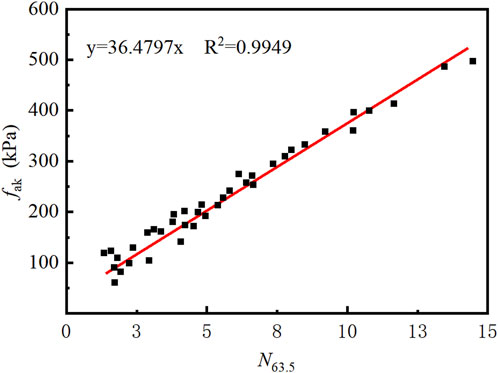
Figure 1. Relationship between DPT blow count and foundation load-bearing capacity.

Table 1. Classification of coral sand compaction degrees.
2.1.2 Classification of reef limestone
The compressive strength of reef limestone is primarily influenced by coral species, rock structure, and the degree and type of cementation, where the cementation degree is the most significant factor. Therefore, the degree of cementation is employed as the classification standard for assessing the engineering properties of reef limestone. Table 2 categorizes reef limestone into five types: strong cementation, relatively strong cementation, moderate cementation, weak cementation, and very weak cementation. The compaction degree of the rock is related to porosity, which in turn is correlated with the velocity of P-waves. Table 3 provides classifications of reef limestone compaction degree based on P-wave velocity or porosity. In cases where evaluations based on P-wave velocity and porosity are inconsistent, the results based on P-wave velocity take precedence.
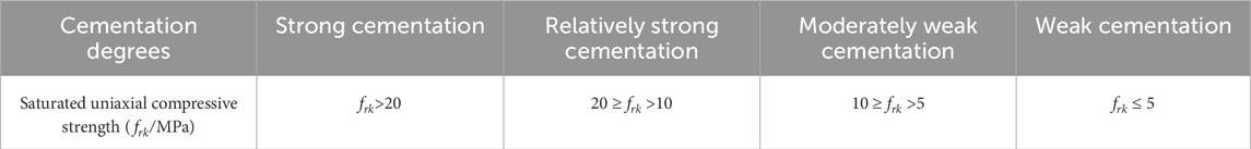
Table 2. Classification of reef limestone cementation degrees.
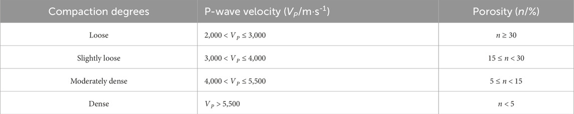
Table 3. Classification of reef limestone compaction degrees.
2.2 Physical and mechanical properties of coral sand
The surface layer of coral islands and reefs is typically composed of coral sand, which can be divided into five types based on particle size: coral gravel sand, coarse sand, medium sand, fine sand, and silty sand. Laboratory triaxial shear tests and lateral earth pressure coefficient tests were performed to analyze the mechanical behaviors of these sand types.
Triaxial tests on coral sand revealed that shear bands consistently formed after shear failure, as depicted in Figure 2. This failure mode differs from the “dilation” failure observed in terrigenous siliceous sand. Table 4 summarizes the shear strength parameters for various coral sand types obtained from triaxial tests. Sands with larger particle sizes exhibited higher peak and residual strengths. The ratio of peak strength to residual strength across the five types of coral sand ranged from 0.63 to 0.83.
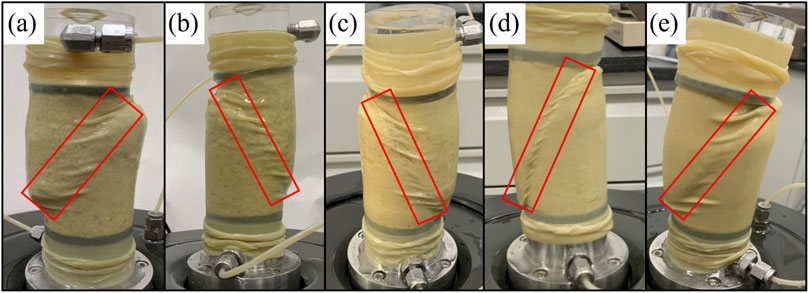
Figure 2. Shear failure modes of coral sand. (a) Gravel sand. (b) Coarse sand. (c) Medium sand. (d) Fine sand. (e) Silty sand.

Table 4. Strength parameters of different sand types.
The lateral earth pressure coefficient (K0) refers to the ratio of horizontal principal stress to vertical stress for soil consolidated under conditions without lateral deformation. K0 tests were performed on coral sand samples in both dry and saturated states to analyze the relationship between horizontal and vertical stresses, as illustrated in Figures 3a,b. Coral silty sand exhibited the highest K0 value, ranging from 0.31 to 0.33, while other coral sand types showed K0 values between 0.22 and 0.31. The K0 values in saturated coral sand samples were slightly higher than those in dry samples, while the K0 value remained consistent across different depths.
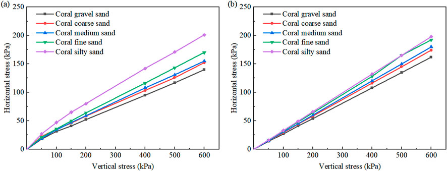
Figure 3. Vertical stress-horizontal stress relationship curves for coral sand. (a) Dry state. (b) Saturated state.
3 Pile foundation load-bearing mechanism in coral reef strata
Bridge foundations typically consist of driven steel pipe piles and cast-in-place concrete piles. The study focused on the vertical load-bearing capacity characteristics of driven steel pipe piles in coral sand strata and cast-in-place concrete piles in reef limestone strata.
3.1 Side friction resistance load-bearing mechanism of driven steel pipe piles in coral sand strata
The physical and mechanical properties of coral sand differ significantly from those of traditional quartz sand. This results in lower load-bearing efficiency of driven steel pipe piles in this stratum. Direct shear tests and model tests were conducted to analyze the side friction resistance load-bearing mechanism for driven piles in coral sands, and the calculation method for side friction resistance of steel pipe piles in coral sand strata was modified.
3.1.1 Interface shear tests
Interface shear tests were conducted between coral reef debris and steel piles under constant normal stiffness conditions, as illustrated in Figure 4. Results indicated that during the initial shear stage, shear strain increased significantly while normal stress decreased sharply. As shear continued, normal stress stabilized. As a result, the sample demonstrated a general tendency towards shear contraction. This behavior was attributed to the relative sliding between steel pipe piles and coral sand, which caused particle overturning, fragmentation, and redistribution. This reorganization filled voids, reduced lateral pressure around the pile, and limited the development of side friction resistance.

Figure 4. Shear contraction behavior of coral reef debris.
3.1.2 Model tests of driven steel pipe piles
Model tests were conducted to investigate the distribution of pile side friction resistance in coral reef strata and evaluate the interaction between coral sand and steel pipe piles. The samples used in the model tests were sourced from the uncemented coral medium sand in Maldives, characterized by a uniformity coefficient (Cu) of 4.87 and a curvature coefficient (Cc) of 0.9, which indicates poorly graded sand. The model box used in this study was a cylindrical structure with a diameter of 2 m and a height of 3 m. The model piles were designed as steel pipe piles with a maximum outer diameter of 0.25 m and a length of 2.0 m. As illustrated in Figures 5a,b, the testing system consisted of a loading plate, a transmission column, a confining pressure loading jack, and an actuator. Eight loading levels were established at 24 kPa, 36.5 kPa, 49 kPa, 74 kPa, 99 kPa, 124 kPa, 174 kPa, and 224 kPa to investigate the ultimate side friction resistance of driven piles and its distribution under varying effective vertical stress conditions.

Figure 5. Driven pile model test. (a) Schematic diagram of the model. (b) Model test photo.
The variation in side friction resistance of piles embedded in quartz sand under different effective vertical stress conditions was calculated based on the model test results for driven piles using the recommended methods from the American Petroleum Institute (API) standards (Institute, 2000). These results were then compared with those obtained from coral medium sand, as depicted in Figure 6. Both types of strata exhibited a parabolic distribution of pipe side friction resistance. Coral sand exhibited a lower pile side friction resistance of approximately 17.5 kPa, which is 21.4% of the pile side friction resistance in quartz sand. This is close to the 27% observed in Jiang’s experimental results (King and Lodge, 1988). The stress conversion showed that the ultimate side friction resistance for coral sand corresponded to an embedding depth of approximately 9.3 m, while for quartz sand, it was about 25 m. This difference was primarily attributed to higher internal friction angle and cohesion in coral sand, which led to an arching effect during deformation and consequently resulted in smaller increments in lateral pressure.
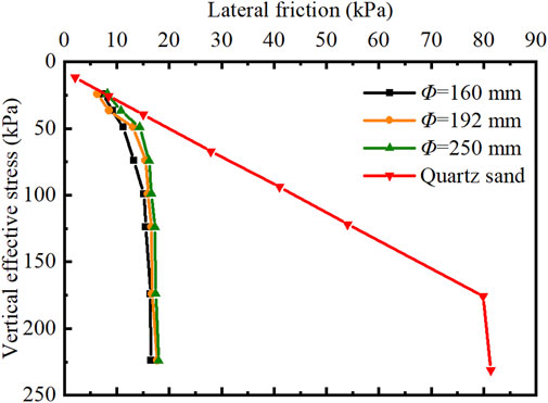
Figure 6. Distribution of pile side friction resistance.
3.1.3 Calculation method for side friction resistance of driven steel pipe piles in coral sand strata
Currently, there is no effective method for calculating side friction resistance of pile foundations in coral reef strata in China. Internationally, the recommended methods from API standards are typically used, which only modify parameters such as the lateral pressure coefficient (k), the friction angle (δ) between the soil and the pile wall, the ultimate unit side friction resistance (fmax), and the ultimate unit end resistance (qmax) (Institute, 2000). However, these methods do not account for the unique properties of coral sand, which makes them unsuitable for calculating pile side friction resistance in coral sand strata. The distribution of side friction resistance for driven piles was simplified to a “triangle + rectangle” configuration based on the model test results. A calculation method for side friction resistance of driven steel pipe piles in coral reef strata was proposed based on API standards, as indicated in Equation 1.
where
The study selected 32 protective tubes of the China-Maldives Friendship Bridge as the research subjects and conducted in situ high-strain testing on the pile foundations, as depicted in Figure 7. The proposed calculation method for side friction resistance in coral reef strata was applied to evaluate the side load-bearing capacity of driven piles in the China-Maldives Friendship Bridge. The computation results were compared with the field test results, as illustrated in Figure 8. The average error between the two was 10.3%. Additionally, the theoretical values were consistently lower than the measured values. This indicates that the calculation method proposed in this study is conservative and validates the rationality of the modified calculation approach.

Figure 7. High-strain hammer test on pile foundations.
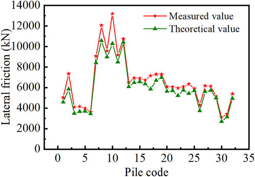
Figure 8. Comparison of theoretical and measured friction resistance.
3.2 Vertical load-bearing mechanism of cast-in-place piles in reef limestone strata
The vertical load-bearing capacity of cast-in-place piles in reef limestone strata primarily depends on the mechanical characteristics of the pile-rock interface and the rock strength. Currently, research on the mechanical response of reef limestone is still in its infancy, and there is a lack of systematic studies on its cementation strength and mechanical properties at the micro-scale. Additionally, there are currently no constitutive models applicable to reef limestone. The unclear failure mechanisms at the pile-reef limestone interface, along with insufficient consideration of factors such as interface morphology, have prevented a thorough understanding of the load-bearing mechanism of cast-in-place piles. Moreover, there is currently no calculation method for determining the load-bearing capacity of cast-in-place piles in reef limestone strata.
3.2.1 C2 of cast-in-place piles in reef limestone strata
The influence mechanism of clean-water borehole wall morphology and the interface condition between reef limestone and cast-in-place piles on the c2 has not been thoroughly investigated. The borehole walls depicted in the reef limestone detection images were simplified into seven different casting interface morphologies, as illustrated in Figure 9. Shear tests were conducted on the reef limestone-concrete interface to investigate the impact of borehole wall morphology on side friction resistance.

Figure 9. Shear test of reef limestone-concrete interface.
The average shear strength of all serrated pile interfaces was calculated and compared with that of straight piles, as depicted in Figure 10. The average shear strengths at both the straight pile and serrated interfaces were found to be comparable under different normal stress conditions, with values of approximately 2.6 MPa. This suggested that the filling state of the interface had a more significant effect on shear strength than the interface morphology. The saturated uniaxial compressive strength of the reef limestone samples ranged from 5.8 to 7.5 MPa. The c2 is defined as the ratio of side friction resistance to saturated uniaxial compressive strength of the pile-side rock, and serves as an important indicator of the efficiency of side friction resistance. Shear tests indicated that the c2 for the embedded segments of cast-in-place piles in reef limestone strata ranged from 0.33 to 0.43, which is significantly higher than the recommended value of 0.05 for terrestrial rocks as specified in the standard (Zhou, 2014). Hence, the differences in the c2 between cast-in-place piles in reef limestone and terrestrial rock strata should be considered in the design process.

Figure 10. Shear strength of straight pile interfaces and average shear strength of serrated interfaces.
3.2.2 Calculation method for cast-in-place piles in limestone strata
The “Specifications for Design of Foundation of Highway Bridges and Culverts” (Zhou, 2014) specifies the formula for calculating the allowable axial compressive capacity of a single rock-socketed bored pile, which is expressed in Equation 3.
where [Ra] is the allowable vertical load-bearing capacity of a single pile (kN); c1 denotes the mobilization coefficient of end friction resistance depending on various factors such as rock integrity; Ap is the cross-sectional area of the pile end (m2); frk represents the standard saturated uniaxial compressive strength of the rock at the pile end (kPa); c2i is the mobilization coefficient of side friction resistance for the ith rock layer determined by rock integrity and compaction degree; u refers to the perimeter of the pile shaft within each soil or rock layer (m); hi indicates the thickness of the pile embedded in each rock layer (m); m is the number of rock layers, li is the thickness of each coral reef layer (m); qsj is the standard side friction resistance for the ith soil layer surrounding the pile (kPa); and n is the number of soil layers.
The study of the side friction resistance mechanism of cast-in-place piles in reef limestone strata and the porous characteristics of reef limestone highlighted a necessity to modify the c2. Field tests were conducted using the self-balancing method to determine the ultimate side friction resistance of cast-in-place piles in reef limestone at the bridge site, as illustrated in Figure 11. As depicted in Table 5, field test results revealed that the ratio of measured ultimate side friction resistance to the saturated uniaxial compressive strength of the pile-side rock ranged from 0.05 to 0.11, with localized values up to 0.128. Terrestrial limestone typically exhibits c2 values varying between 0.024 and 0.04 (CCCC Highway Consultants Co. and Ltd, 2007). The c2 value for clean-water boreholes in reef limestone is approximately 2–3 times that in terrestrial limestone, yet remains lower than the values obtained from laboratory shear tests for rock-socketed segments. This is likely because laboratory reef limestone samples are finely processed with minimal damage, whereas on-site drilling produces unavoidable damage to borehole wall rock layers. Moreover, design code-recommended values are established through extensive practical applications and include safety factors. Therefore, during the design phase, the c2 value for rock-socketed segments of cast-in-place piles in reef limestone can be appropriately increased based on the rock’s integrity and mechanical properties. A recommended range for the c2 is 0.05–0.11.
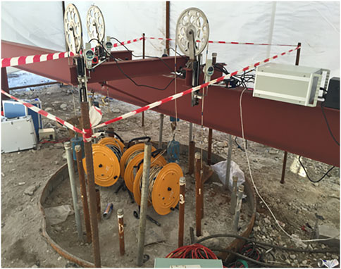
Figure 11. Field self-balancing pile test.
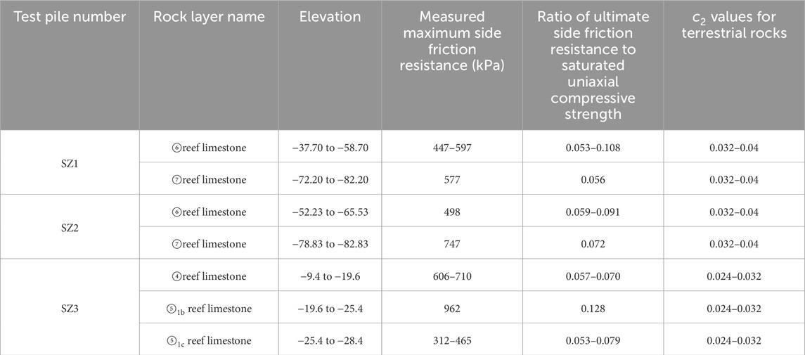
Table 5. Measured c2 from pile testing.
4 Construction techniques and equipment development for driven steel pipe piles in coral debris strata
4.1 Construction techniques and equipment development for driven steel pipe piles in coral debris strata
For offshore bridge projects, the construction of driven steel pipe piles is affected by ocean currents and waves, which can result in low accuracy in pile positioning and increased construction safety risks. Furthermore, the presence of cavities or weak layers in the coral reef strata poses a risk of “pile slippage” during installation. Figure 12 illustrates the developed guide frame equipped with hydraulic automatic opening and closing chuck, which effectively mitigates safety risks associated with excessive swaying during the hoisting of the steel casing. The cantilever guiding frame system with a fuse mechanism can prevent impact on the guiding frame by triggering the fuse in case of “pile slipping.” These methods ensured that the installation precision of steel pipe piles under ocean current and wave conditions met the necessary standards (as depicted in Figure 13): planar displacement <25 cm and inclination <0.5%.
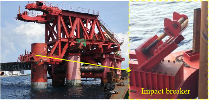
Figure 12. Guide frame with hydraulic automatic opening and closing chuck and impact breaker.
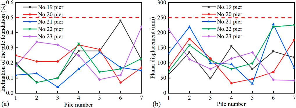
Figure 13. Precision of pile installation. (a) Inclination of the pile foundation. (b) Planar displacement of the pile foundation.
4.2 Construction techniques and equipment development for cast-in-place piles in reef limestone strata
The porous and heterogeneous characteristics of reef limestone strata pose challenges to traditional drilling methods for cast-in-place piles, including excessive hole enlargement and significant deviations in vertical alignment. Clean-water drilling experiments have established control parameters for various coral reef strata, which ensure safe and efficient drilling. The detailed control parameters are presented in Table 6. The methods for controlling borehole diameters, such as extended barrel drilling for circular cuts and tooth-cutting drill bits for hard-soft interbedded reef limestone strata, were employed to mitigate borehole wall collapse and address the prevalence of voids in coral reef strata. These approaches effectively controlled hole enlargement. Additionally, modifications to rotary and reverse circulation drill bits ensured high-quality drilling in hard-soft interbedded reef limestone strata. The modified drilling equipment can be seen in Figures 14a,b. This resulted in a vertically smooth borehole wall morphology, as illustrated in Figures 14c,d.
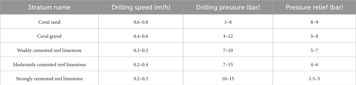
Table 6. Control parameters for clean-water rotary drilling.
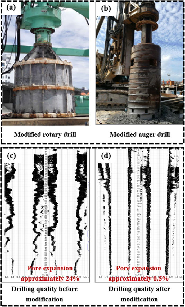
Figure 14. The modified drilling equipment and a comparison of its effects. (a) Modified rotary drill. (b) Modified auger drill. (c) Drilling quality before modification. (d) Drilling quality after modification.
5 Engineering applications
The China-Maldives Friendship Bridge (see Figure 15) is located in the North Malé Atoll of the Maldives. It spans the Gaadhoo Koa Strait and connects three adjacent islands: Malé Island, Airport Island, and Hulhumalé Island. The total route length is 2.0 km, where the bridge segment measures 1.39 km. The main bridge is a six-span hybrid beam rigid frame bridge with a length of 760 m. Piers 19 to 23 of the main bridge utilize variable cross-section steel pipe composite pile foundations. The diameters of steel casings range from 3.2 m to 3.6 m, and the maximum length of the cast-in-place piles is 110 m. The Maldives islands are surrounded by open waters with strong ocean currents, high waves, and long periods, which present significant challenges to construction.

Figure 15. The China-Maldives friendship bridge.
Relevant research findings and technologies have been successfully applied in the design and construction of the pile foundations and superstructure of the China-Maldives Friendship Bridge. The load-bearing mechanism of pile foundations under coral reef geological conditions has been defined. The developed hydraulic automatic opening and closing chuck guide frame with a fusing mechanism allows for driven pile placement with a planar displacement of less than 25 cm and an inclination of less than 0.5%. The construction technique for cast-in-place piles in soft-hard interbedded reef limestone strata results in a verticality error of less than 0.5%. By applying these cross-sea bridge construction technologies, the project team improved efficiency and ensured successful project execution.
6 Conclusion and suggestions
This study addressed construction challenges for cross-sea bridges on coral reef substrates. Additionally, we proposed an engineering classification system for coral reef soils and rock masses exhibiting binary sedimentation fabrics through theoretical analysis, field investigations, and laboratory experiments. The load-bearing mechanisms and construction techniques of pile foundations in coral reef strata were explored. The findings have been applied in the China-Maldives Friendship Bridge. The main conclusions are as follows:
1. The engineering properties of coral reef soils and rock masses differed markedly from those of typical rock and soil types. The coral debris strata can be categorized according to particle size distribution, while their engineering compactness should be determined from dynamic penetration test results. Furthermore, the static lateral earth pressure coefficient (K0) of various coral sands varied significantly, with values ranging from 0.22 to 0.33.
2. The construction of driven piles in coral sand strata resulted in fragmentation and redistribution of coral sand particles. This led to lower pile side friction resistance of approximately 17.5 kPa, which is about 21.4% of that found in quartz sand. A calculation formula for side friction resistance of driven piles in coral sand strata was proposed based on the model test results.
3. Seven simplified casting interface shear characteristics at the reef limestone-pile interface were analyzed. The recommended range for the c2 of cast-in-place piles embedded in reef limestone strata is between 0.05 and 0.11, which is 2–3 times that observed in terrestrial limestone.
4. A hydraulic automatic opening and closing chuck guide frame system with a fusing mechanism was developed. Additionally, methods for controlling borehole diameters, such as extended barrel drilling for circular cuts and tooth-cutting drill bits for hard-soft interbedded reef limestone strata, were proposed. These advancements enhance both the efficiency and quality of pile foundation construction in coral strata.
Data availability statement
The original contributions presented in the study are included in the article/supplementary material, further inquiries can be directed to the corresponding author.
Author contributions
YuZ: Conceptualization, Project administration, Writing – original draft. YoZ: Formal Analysis, Methodology, Supervision, Writing – review and editing. CY: Data curation, Investigation, Writing – original draft. FJ: Data curation, Investigation, Writing – original draft. PC: Resources, Validation, Writing – review and editing.
Funding
The author(s) declare that financial support was received for the research and/or publication of this article. This work was supported by Hubei Provincial Natural Science Foundation of China (Grant No. 2023AFB508).
Conflict of interest
Authors YuZ, YoZ, CY, FJ, and PC were employed by CCCC Second Harbor Engineering Co., Ltd.
Author YuZ was employed by CCCC Wuhan Harbour Engineering Design & Research Company Ltd.
Generative AI statement
The author(s) declare that no Generative AI was used in the creation of this manuscript.
Any alternative text (alt text) provided alongside figures in this article has been generated by Frontiers with the support of artificial intelligence and reasonable efforts have been made to ensure accuracy, including review by the authors wherever possible. If you identify any issues, please contact us.
Publisher’s note
All claims expressed in this article are solely those of the authors and do not necessarily represent those of their affiliated organizations, or those of the publisher, the editors and the reviewers. Any product that may be evaluated in this article, or claim that may be made by its manufacturer, is not guaranteed or endorsed by the publisher.
References
Beger, M., Sommer, B., Harrison, P. H., Smith, S. D., and Pandolfi, J. M. (2014). Conserving potential coral reef refuges at high latitudes. Divers. Distributions 20 (3), 245–257. doi:10.1111/ddi.12140
Carter, J. P., Johnston, I. W., and Fahey, M. (1988). Triaxial testing of north rankin calcarenite. Proceeding of the international conference on calcareous sediments. Perth, Rotterdam: Balkema Publishers, 515–530.
CCCC Highway Consultants Co., Ltd. (2007). JTG D63-2007 code for design of ground base and foundation of highway bridges and culverts. Beijing: China Communications Press.
Chortis, G., Askarinejad, A., Prendergast, L., Li, Q., and Gavin, K. (2020). Influence of scour depth and type on p-y curves for monopiles in sand under monotonic lateral loading in a geotechnical centrifuge. Ocean. Eng. 197, 106838. doi:10.1016/j.oceaneng.2019.106838
Clark, A. R., and Walker, B. F. (1997). A proposed scheme for the classification and nomemclature for use in the engineering description on Middle Eastern sedimentary rocks. Géotechnique 27 (1), 93–99. doi:10.1680/geot.1977.27.1.93
Gao, R., and Ye, J. H. (2023). Mechanical behaviors of coral sand and relationship between particle breakage and plastic work. Eng. Geol. 316, 107063. doi:10.1016/j.enggeo.2023.107063
Ghazali, F. M., Sotiropoulos, E., and Mansour, O. A. (1988). Large-diameter bored and grouted piles in marine sediments of the Red Sea. Can. Geotechnical J. 25 (4), 826–831. doi:10.1139/t88-090
Ho, H. M., Malik, A. A., Kuwano, J., Brasile, S., Tran, T. V., and Mazhar, M. A. (2022). Experimental and numerical study on pressure distribution under screw and straight pile in dense sand. Int. J. Geomech. 22 (9), 04022139. doi:10.1061/(asce)gm.1943-5622.0002520
Höppner, R., and Boley, C. (2022). Erkenntnisse zum tragverhalten von fertigschraubpfählen unter axialer belastung. Bautechnik 99 (9), 656–664. doi:10.1002/bate.202200030
Institute, A. P. (2000). Recommended practice for planning, designing and constructing fixed offshore platforms (RP 2A-WSD).
Jiang, H. (2009). Research on bearing behavior of pile foundations in calcareous sand. Wuhan: University of the Chinese Academy of Sciences Institute of Rock and Soil Mechanics.
King, R., and Lodge, M. (1988). North west shelf development—The foundation engineering challenge. Proceeding of the international conference on calcareous sediments. Perth, Rotterdam: Balkema Publishers, 555–564.
Lin, X., Zhang, J., Wang, R., Liu, W., and Zhang, Y. (2019). Scour around a mono-pile foundation of a horizontal axis tidal stream turbine under steady current. Ocean. Eng. 192, 106571. doi:10.1016/j.oceaneng.2019.106571
Liu, H. F., Zhu, C. Q., Wang, R., Cui, X., and Wang, T. (2021). Characterization of the interface between concrete pile and coral reef calcarenite using constant normal stiffness direct shear test. Bull. Eng. Geol. Environ. 80, 1757–1765. doi:10.1007/s10064-020-02039-8
Lu, J. C., and Luo, H. (2016). Enhineering geological characteristic and evaluation for construction site of cross-sea bridge in male-airport island. Constr. Des. Eng. 5, 71–74. doi:10.13616/j.cnki.gcjsysj.2016.05.017
Nansha Integrated Scientific Expedition Team and Chinese Academy of Sciences (1992). Quaternary coral reef geology of the yongshu reef, nansha islands. Beijing: China Ocean Press.
Qin, W., Dai, G. L., and Ma, L. Z. (2019). In-situ static loading tests of prestressed high strength concrete (PHC) pile in coral strata. Rock Soil Mech. 40, 381–389. doi:10.16285/j.rsm.2019.0149
Schmüdderich, C., Shahrabi, M. M., Taiebat, M., and Alimardani Lavasan, A. (2020). Strategies for numerical simulation of cast-in-place piles under axial loading. Comput. Geotech. 125, 103656. doi:10.1016/j.compgeo.2020.103656
Shan, H. G., and Wang, R. (2000). Development of study on pile in calcareous sand. Rock Soil Mech. 21 (3), 299–304. doi:10.16285/j.rsm.2000.03.027
Wan, Z. H., Dai, G. L., and Gong, W. M. (2018). Enhanced mechanism of post-grouting pilein coral-reef limestone formations. Rock Soil Mech. 39 (2), 467–473. doi:10.16285/j.rsm.2017.1124
Wang, G. (2001). Sedimentology of coral reef areas in the South China Sea. Beijing: China Ocean Press.
Wang, R., Song, C. J., and Zhao, H. T. (1997). Coral reef engineering geology of nansha islands. Beijing: Science Press.
Xu, X. L., Lei, X., and Wang, T. L. (2022). Experimental study on shear mechanical properties of pile-coral sand interface. Chin. J. Undergr. Space Eng. 18, 1891–1897+1905.
Xu, M., Zhang, F., Ni, P., and Mei, G. (2023). Load–settlement behaviour of membrane-confined grouted pile: experimental and analytical study. Acta Geotech. 18 (5), 2777–2793. doi:10.1007/s11440-022-01711-5
Yao, T., Cao, Z. W., and Li, W. (2024). On the mechanical behaviour of a coral silt from the South China Sea. Géotechnique, 1–14. doi:10.1680/jgeot.24.00012
Yu, K. F., Zhang, G. X., and Wang, R. (2014). Studies on the coral reefs of the South China Sea: from global change to oil-gas exploration. Adv. Earth Sci. 29 (11), 1287–1293.
Zhong, Y., Wang, R., and Li, Q. (2020). Physical and engineering characteristics of reef limestone: a review. Sci. Technol. 38, 57–70.
Zhou, Y. (2014). Teoretical analysis and experimental studies on residual stress of jacked open-ended concrete pipe piles. Hangzhou: Zhejiang University.
Keywords: coral reef, bridge engineering, pile foundation, load-bearing mechanism, construction equipment
Citation: Zhong Y, Zhang Y, Yu C, Ji F and Chen P (2025) Construction techniques for cross-sea bridges in coral reef and island environments. Front. Earth Sci. 13:1707062. doi: 10.3389/feart.2025.1707062
Received: 17 September 2025; Accepted: 16 October 2025;
Published: 29 October 2025.
Edited by:
Tongming Qu, Hong Kong University of Science and Technology, ChinaCopyright © 2025 Zhong, Zhang, Yu, Ji and Chen. This is an open-access article distributed under the terms of the Creative Commons Attribution License (CC BY). The use, distribution or reproduction in other forums is permitted, provided the original author(s) and the copyright owner(s) are credited and that the original publication in this journal is cited, in accordance with accepted academic practice. No use, distribution or reproduction is permitted which does not comply with these terms.
*Correspondence: Yu Zhong, emhvbmd5dTEyMTZAMTYzLmNvbQ==