 Longqing Zou1
 Shaoping Deng
- 1Shale Gas Exploration and Development Department, CNPC Chuanqing Drilling Engineering Company Limited, Chengdu, Sichuan, China
- 2Institute for Disaster Management and Reconstruction, Sichuan University, Chengdu, China
- 3Institute of New Energy and Low-Carbon Technology, Sichuan University, Chengdu, China
Wellbore blockage is a significant challenge hindering the efficient production of shale gas in the Sichuan-Chongqing region. To enable precise unblocking, it is crucial to understand the physical and mechanical properties of these complex downhole deposits. This study conducted a comprehensive analysis of blockage samples retrieved from a shale gas well in the Weiyuan area. We employed X-ray diffraction (XRD), scanning electron microscopy with energy-dispersive X-ray spectroscopy (SEM-EDS), and thermogravimetric analysis (TG-DTG) to characterize the samples’ composition, microstructure, and thermal behavior. The results identified the blockage as a complex mixture primarily composed of quartz, Fe3O4, BaSO4, rock cuttings, and rubber particles. Furthermore, artificial blockage samples were fabricated under simulated downhole stress conditions (1–45 MPa) to evaluate their mechanical properties. Tests revealed that both compressive and shear strength increased with the forming stress. Based on the acquired mechanical parameters, a mechanical model was established to predict the pressure differential required to dislodge a blockage by wellhead pressurization. The model indicates that for blockages longer than half the pipe diameter (L > D/2), the required pressure becomes impractically high, rendering this method ineffective and necessitating combined unblocking strategies. This research provides a scientific basis for optimizing unblocking techniques and ensuring the safe, efficient development of shale gas resources.
1 Introduction
In recent years, as shale gas exploration and development intensifies in the Sichuan-Chongqing region, production from typical blocks such as Weiyuan and Changning has continuously increased (Bao et al., 2025). However, this rapid development has been accompanied by increasingly frequent and severe wellbore blockage incidents, which now pose a significant threat to production efficiency and continuity (Xie, 2025; Wang, 2018; Li et al., 2024). The root of this issue lies in the nature of hydraulic fracturing itself—a process involving complex well architectures and the use of substantial volumes of downhole materials, including drilling mud, fracturing fluids, proppants, and bridge plugs. Inevitably, these operations lead to incomplete drill-out and flowback, proppant flowback, and the infiltration of shale fragments into the wellbore (Yuan et al., 2024; Yang et al., 2024; Li L. et al., 2025). When not promptly removed, these materials accumulate, forming obstructions that impair gas extraction and can ultimately result in full-scale production shutdowns (Ye et al., 2025).
Wellbore blockages are complex heterogeneous mixtures formed under downhole conditions through interrelated physical and chemical processes. They exhibit considerable diversity in type, size, and physical properties (Yang et al., 2025). Effective remediation, therefore, requires a comprehensive strategy that considers the blockage composition, physicochemical characteristics, location, and formation mechanism to select an appropriate unblocking technology. Current remediation methods are broadly categorized as physical, chemical, or hybrid physical-chemical techniques (Li X. et al., 2025; Zhang et al., 2025). Among these, hybrid approaches have emerged as the leading trend, as their synergistic action enhances unblocking efficiency, boosts production recovery, and reduces operational costs (Zou et al., 2024).
Despite these advancements, a significant gap remains in current practices. Existing methods predominantly prioritize chemical agent selection based on compositional analysis, with physical interventions playing a secondary role. Consequently, the intrinsic physical and mechanical properties of the blockages themselves have received comparatively limited attention (AlQuraishi et al., 2024; Peng et al., 2021; Lu et al., 2025). This oversight is compounded by a practical challenge: retrieving representative, in-situ blockage samples is inherently difficult. Specimens brought to the surface are often loose, poorly consolidated, and unrepresentative of their downhole state (Wang et al., 2021; Tan, 2022), making it difficult to accurately characterize their key mechanical parameters. This creates a persistent obstacle to optimizing unblocking technologies.
Since the fundamental objective of unblocking is to fracture or displace the obstruction to restore wellbore access, mechanical properties—such as strength and elastic modulus—are critical. These parameters not only dictate the effectiveness of physical disruption methods but also contain valuable insights into the blockage’s formation history and internal structure. A thorough understanding of these properties is therefore essential for developing targeted, efficient remediation strategies and for optimizing overall shale gas production.
To address these challenges, this study focuses on blockage samples recovered from a shale gas well in the Weiyuan area. We conducted a systematic laboratory investigation to determine their composition, microstructure, and macro-mechanical behavior. The relationship between their deformation, failure characteristics, and mechanical parameters was rigorously analyzed. Furthermore, the derived data were used to establish an idealized mechanical model for physical unblocking. The findings of this research are expected to provide a scientific basis for optimizing downhole remediation strategies and enhancing the safety and efficiency of shale gas production.
2 Materials and methods
2.1 Materials
The blockage samples collected for this study were obtained from flowback operations in a shale gas well located in the Weiyuan area, Sichuan, China. Initial visual inspection indicated that the material was generally loose and soil-like in appearance. However, optical microscopy revealed distinct differences from conventional soil. As shown in Figure 1, microscopic examination identified numerous small, uniformly shaped yellow spheres, along with occasional larger metallic chips, rubber particles, and flaky yellow solids, all adhered to or mixed with abundant brownish, clay-like material.

Figure 1. The wellbore blockages under microscope: (a) The morphology of blockages, (b) Quartz and rubber and (c) Coating and metal fragments.
Given the nature of hydraulic fracturing in shale gas wells, flowback solids commonly include proppant quartz sand, rock cuttings, casing coatings, and bridge plug debris (Gao et al., 2016). Based on these characteristics, the regularly shaped spheres of consistent size were preliminarily identified as quartz sand. The metallic chips, which exhibited clear ferromagnetic properties, are likely iron scraps derived from casing wear. The irregular rubber particles are inferred to originate from bridge plugs, while the bright, curved flaky yellow solids are consistent with casing coating material. The adhering brownish soil-like substance is interpreted as rock cuttings.
To further verify the composition of the observed materials, X-ray diffraction (XRD) analysis was performed on the blockage samples using a Rigaku SmartLab diffractometer. The measurement was conducted over a 2θ range of 5°–85° with a step size of 0.02° and a scanning speed of 1°/min. The resulting diffraction pattern is shown in Figure 2.
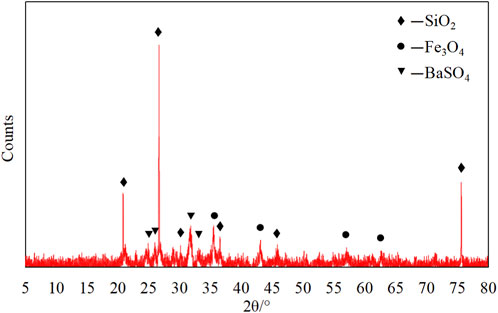
Figure 2. XRD patterns of wellbore blockages.
The XRD results indicate the presence of quartz (peaks at 20.9°, 26.7°, and 75.6°), Fe3O4 (peaks at 35.5° and 43.1°), and BaSO4 (peaks at 26.5° and 31.6°). Among these, the quartz diffraction peaks are the most prominent, consistent with the abundant quartz sand visually observed in the samples. The Fe3O4 is attributed to casing wear, while the BaSO4 may originate either from dislodged casing coating (Zhang et al., 2019) or from barite additives used in drilling fluids (Ibrahim et al., 2017).
2.2 Test specimens
To evaluate the physical and mechanical properties of the loosely aggregated blockage material, a compaction molding method—analogous to artificial core preparation techniques—was employed to simulate the downhole condition of the blockages (Bai et al., 2023; Song et al., 2019). As illustrated in Figure 3, the material was placed into a mold and subjected to varying stress levels for a specified duration. After compaction, the samples were retrieved for mechanical testing, including compressive and shear strength measurements.
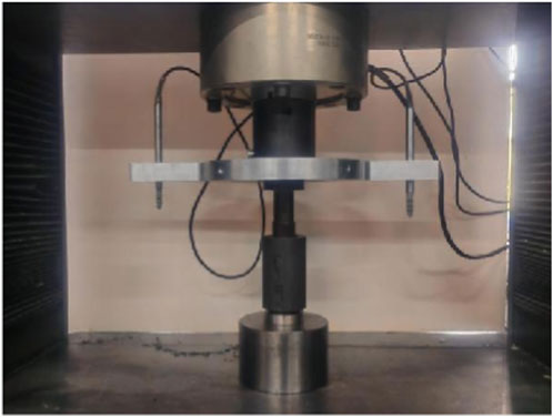
Figure 3. The sample production process.
Due to uncertainties regarding the actual downhole location and in-situ environment of the blockages, the applied stress conditions were estimated based on regional shale gas well data (Wang, 2023; He et al., 2025). Assuming a hydrostatic pressure regime with a maximum vertical depth of 4,000 m and a fracturing fluid density of 1.1 g/cm3, the maximum hydrostatic pressure was calculated to be 45 MPa. Accordingly, four stress levels—1, 15, 30, and 45 MPa—were selected to represent different possible depths, each maintained for a 6-h loading period. For each condition, three cylindrical samples with dimensions of φ25 × 50 mm were prepared for compressive strength tests, and three with dimensions of φ25 × 25 mm for shear strength tests.
2.3 Test methods
2.3.1 Compressive and shear strength tests
Upon completion of the artificial blockage samples, they were immediately demolded and subjected to macroscopic mechanical testing to accurately determine their mechanical properties. The compressive strength test was conducted under displacement control at a loading rate of 0.2 mm/min. The load–displacement curve was recorded throughout the test until sample failure occurred. The peak load from this curve was taken as the compressive strength of the sample, calculated using Equation 1. The average value from three replicate tests was reported.
Where
The shear strength of the blockage samples was determined using the direct shear method, with displacement control at a loading rate of 0.5 mm/min. The load–displacement curve was continuously recorded until specimen failure. The peak load was adopted as the shear strength, computed according to Equation 2. Results are presented as the average of three tests.
In the equation:
2.3.2 Thermogravimetric analysis
To quantitatively evaluate the influence of different components within the blockage material—whose exact composition was initially unknown—thermogravimetric analysis (TGA) was employed. The analysis was performed using a NETZSCH STA 449 F5 simultaneous thermal analyzer under an argon atmosphere. Prior to testing, the blockage samples were thoroughly crushed. The temperature was programmed to increase from 80 °C to 1,200 °C at a constant heating rate of 5 °C/min. The derivative thermogravimetric (DTG) curve was subsequently derived from the obtained TG data.
2.3.3 Scanning electron microscopy
SEM was utilized to examine the micro-morphology and structure of the blockage samples, as well as to analyze their elemental composition. Observations were carried out using a Hitachi SU8230 cold field emission scanning electron microscope, which was equipped with an Oxford Instruments X-Max 80 EDS detector for energy-dispersive X-ray spectroscopy (EDS). Sample preparation involved drying, crushing, magnetic separation, and subsequent platinum coating to ensure conductivity and image clarity.
3 Results and discussion
3.1 Mechanical properties
3.1.1 Compressive strength
The compressive strength test results for the artificial blockage samples are summarized in Table 1 and Figure 5, with photographs of the post-test specimens shown in Figure 4. As expected, both the sample density and compressive strength exhibit a clear increasing trend with higher applied stress levels during sample preparation. Correspondingly, the slope of the force-displacement curve prior to the peak—representing the compressive elastic modulus—also increased significantly.

Table 1. The compressive strength of artificial blockages.
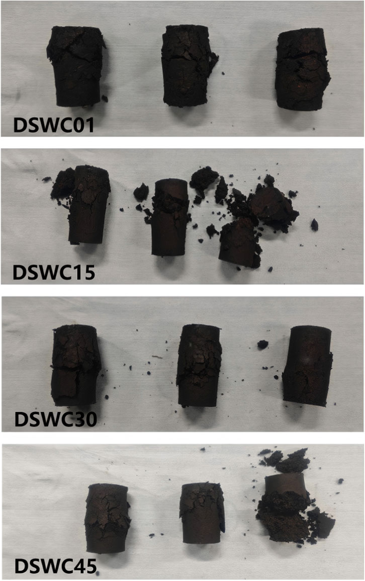
Figure 4. The artificial wellbore blockages after the compressive strength test.
It is noteworthy that despite the identical preparation and testing procedures employed, the measured strength exhibited considerable variability, as indicated by an increasing coefficient of variation. Post-test analysis suggests that this scatter is likely attributable to the rebound effect of large rubber particles embedded in the samples. These particles deform under compressive load but rapidly rebound upon stress release. This rebound behavior becomes more pronounced at higher stress levels, frequently leading to sample deformation and cracking, thereby resulting in a reduction of the measured compressive strength.
3.1.2 Shear strength
The direct shear test results for the artificial blockage samples are provided in Table 2 and Figure 5, with post-test specimens illustrated in Figure 6. Similar to the compressive strength results, the shear strength demonstrates a pronounced and consistent increase with rising stress levels. The shear elastic modulus, derived from the pre-peak slope of the force–displacement curve, also rose significantly.
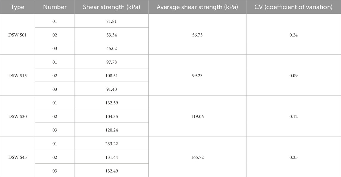
Table 2. The shear strength of artificial blockages.
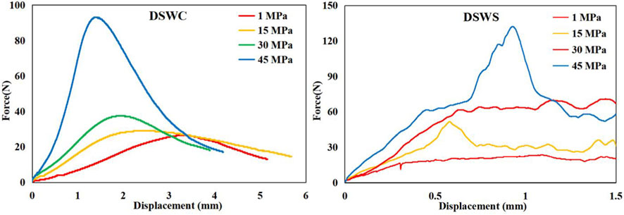
Figure 5. The force-displacement curves of compressive strength (left) and shear strength (right) of artificial blockages.
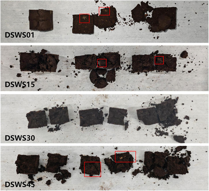
Figure 6. The artificial wellbore blockages after the shear strength test.
A higher degree of data scatter was observed at both the lowest and highest stress levels. This variability is attributed to the presence of rubber particles, which act as significant defects along the shear plane under extreme stress conditions—particularly when they rebound or are poorly bonded to the surrounding matrix. For instance, in samples exhibiting relatively low shear strength such as DSWS45-02 (Figure 6), large rubber particles were identified on both sides of the fracture interface, as highlighted within the red boxes. The shear force–displacement curves exhibited multiple peaks; however, the samples were considered to have failed completely at the first peak. The subsequent residual force is attributed to frictional resistance along the uneven failure surface between the separated sample halves.
Based on the Mohr-Coulomb failure criterion, the shear strength parameters of the blockage material were determined as follows: cohesion c = 56.73 kPa and internal friction angle φ = 17.03°.
3.2 Microscopic morphology
Under SEM observation, well-defined, coarse quartz particles were clearly identified within the blockage material, with numerous irregular aggregates adhering to their surfaces, as shown in Figure 7a. Meanwhile, the majority of the blockage material exhibited irregular morphologies, as illustrated in Figure 7b, necessitating EDS analysis for precise compositional identification.
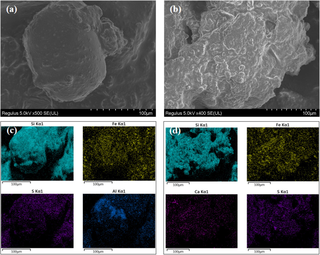
Figure 7. SEM (a,b) and EDS (c,d) image of the blockages: (a) Quartz particles, (b) Rock debris, (c) The distribution of different elements on quartz particles and (d) The distribution of different elements on rock debris.
EDS results indicated a significant presence of silicon. While this is partly attributable to quartz sand, it may also originate from clay minerals such as illite or montmorillonite present in rock cuttings, as supported by the concurrent detection of substantial aluminum and calcium oxides. In addition, the surfaces of quartz and other particulate matter were extensively covered with fine debris, which could not be identified morphologically. EDS analysis of these fine particles revealed high iron oxide content and considerable sulfur. Given the low X-ray count rates (CPS) for sodium and barium, the detected sulfur is likely derived from pyrite in the formation or from reactions between hydrogen sulfide and the casing (Liu et al., 2019; Dai et al., 2025).
3.3 Component analysis by TG-DTG
Figure 8 and Table 3 present the results of the thermogravimetric analysis. The DTG curves show three distinct peaks at approximately 250 °C, 400 °C, and 850 °C which are indicative of different decomposition stages within the wellbore blockage material. By integrating these findings with SEM observations and other analytical results, it is possible to infer the substances corresponding to each peak.
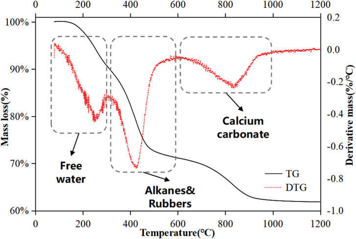
Figure 8. The TG-DTG curves of blockages.
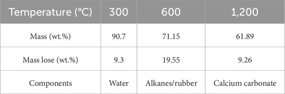
Table 3. The results of the TG test.
The initial mass loss of 9.3 wt.% below 300 °C is primarily attributed to the evaporation of free water and the removal of chemically bound water from minerals and corrosion products such as rust (Yan et al., 2013; Li et al., 2016). As the temperature increases to 600 °C, a significant mass reduction of 19.55 wt.% occurs, which corresponds to the decomposition of organic components. These may include residual oils, fracturing fluid additives—for instance, alkanes like hexadecane and tetracosane (Zhang et al., 2021; Jameel et al., 2017)—and rubber particles from bridge plugs.
Beyond 600 °C, the rate of mass loss decreases noticeably. A broad DTG peak around 850 °C, accompanied by a mass loss of 9.26 wt.%, is likely due to the decomposition of carbonate and clay minerals—such as calcium carbonate and chlorite—present in the drilled cuttings (Zhuang et al., 2025; Bloise et al., 2016). When the temperature exceeds 1,000 °C, the decomposition process becomes very slow, as the remaining residue consists mainly of highly stable oxides like Fe2O3, CaO, SiO2, and Al2O3.
4 Mechanical modeling of wellbore unblocking
For pre-existing wellbore blockages, applying wellhead pressure to restore flow represents the most straightforward remediation approach. Utilizing the mechanical parameters obtained from earlier experiments, we developed a mechanical model (Figure 9) to estimate the pressure differential required to dislodge a blockage using this method.
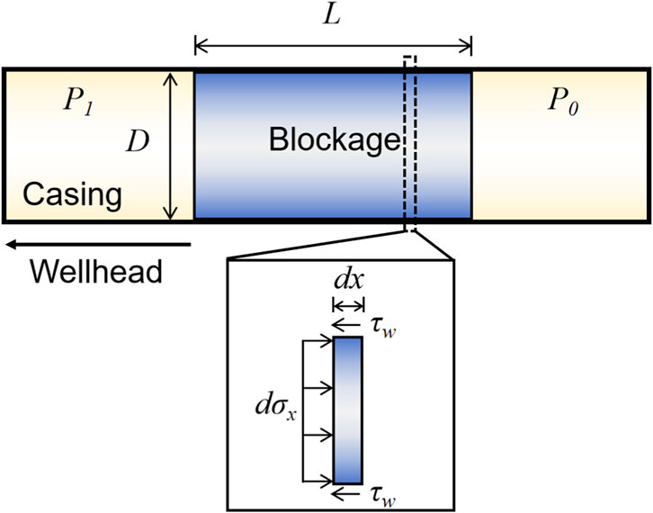
Figure 9. Mechanical model of the blockage in the casing.
The model considers a cylindrical plug of length L fully obstructing a straight pipe of inner diameter D. It incorporates the cohesion c, internal friction angle ϕ of the blockage material, the coefficient of friction μ at the pipe wall, and the initial pipeline pressure P0. The analysis combines soil pressure theory with mechanical equilibrium of the plugged material. The following assumptions were adopted to facilitate the calculation:
• The pipeline is straight, and the blockage is uniformly distributed within it.
• The blockage material resembles soil and follows the Mohr-Coulomb failure criterion.
• The shear stress at the pipe wall depends on cohesion cc and friction coefficient μ, with radial and axial stresses related by the lateral earth pressure coefficient K0.
• The blockage moves as a consolidated plug during unblocking, and the pressure differential must overcome the total shear resistance along the pipe wall.
• The self-weight, dynamic effects, and compressibility of the blockage are neglected.
A differential force balance was established for an infinitesimal segment of the blockage. The axial stress
while the wall shear stress
Balancing axial and shear forces yields the governing differential equation, Equation 5,
The pressure differential
where P1 is the applied upstream pressure. A simplified formula, Equation 7, applies for short blockages.
This methodology explicitly accounts for wall friction and the intrinsic mechanical properties of the blockage material. Assuming an initial in-situ pressure P0 of 45 MPa, a production casing inner diameter of 4.5 inches (114.3 mm), and a measured wall friction angle of 38°, the required pressure differential for dislodging blockages of varying lengths was calculated (Figure 10). For short blockages (L < D/2), the required pressure increases gradually and remains relatively low. In this regime, the blockage is more likely to fail by shear rather than being pushed as a consolidated plug. However, once the blockage length exceeds half the pipe diameter (L > D/2), the required pressure differential rises rapidly. At this point, the blockage behaves as a consolidated plug that is highly resistant to compressive or shear failure, making it practically infeasible to dislodge by merely increasing the upstream pressure. Alternative unblocking techniques are therefore necessary.
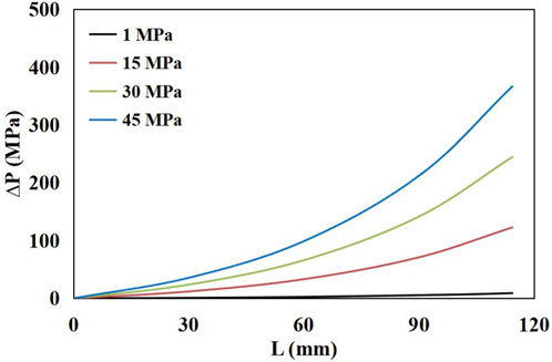
Figure 10. The pressure for unblocking blockages of different lengths and depths.
5 Conclusion
This study systematically investigated the origin, composition, and mechanical properties of wellbore blockages from a shale gas well in the Weiyuan area. Key findings are summarized as follows:
• The blockage is a heterogeneous mixture of proppant, formation debris, and process-related solids, formed by combined deposition under downhole conditions.
• Mechanical strength increases with consolidation stress but is compromised by rubber particles, which introduce variability and promote stress-release cracking.
• A mechanical model reveals a critical length (L ≈ D/2) beyond which pressure-driven unblocking becomes impractical due to exponentially rising pressure requirements.
• Effective remediation must consider blockage composition, length, and mechanical properties, favoring integrated physical-chemical methods over simple pressurization for long blockages.
The current model provides a foundational understanding of the unblocking process. However, the formation history of a blockage critically determines its mechanical response. Future research will employ full-scale flow loops to investigate the effects of gravity-driven deposition, thereby enhancing the field relevance of the model.
Data availability statement
The raw data supporting the conclusions of this article will be made available by the authors, without undue reservation.
Author contributions
LZ: Project administration, Methodology, Investigation, Supervision, Resources, Writing – review and editing, Funding acquisition, Conceptualization. JX: Project administration, Methodology, Resources, Conceptualization, Investigation, Supervision, Funding acquisition, Writing – review and editing. LY: Funding acquisition, Project administration, Resources, Supervision, Methodology, Writing – review and editing, Investigation, Conceptualization. CD: Investigation, Conceptualization, Resources, Project administration, Funding acquisition, Writing – review and editing, Methodology, Supervision. YW: Investigation, Writing – review and editing, Funding acquisition, Supervision, Conceptualization, Project administration, Methodology. SD: Writing – original draft, Formal Analysis, Data curation, Methodology, Investigation, Writing – review and editing.
Funding
The authors declare that financial support was received for the research and/or publication of this article. This study is supported by the project “Mechanical Experiment of Fracturing Simulation Based on Water Hammer Effect and Research on Mechanical Properties of Wellbore Blockages” of CNPC Chuanqing Drilling Engineering Company Limited (No. 24H1698).
Acknowledgements
We acknowledge the assistance of CNPC Chuanqing Drilling Engineering Company Limited in providing the samples and supporting engineering data. We are also grateful for the constructive comments from the reviewers and our editor.
Conflict of interest
Authors LZ, JX, LY, CD, and YW were employed by CNPC Chuanqing Drilling Engineering Company Limited.
The remaining author declares that the research was conducted in the absence of any commercial or financial relationships that could be construed as a potential conflict of interest.
The authors declare that this study received funding from CNPC Chuanqing Drilling Engineering Company Limited. The funder had the following involvement in the study: providing the samples and supporting engineering data.
Generative AI statement
The authors declare that no Generative AI was used in the creation of this manuscript.
Any alternative text (alt text) provided alongside figures in this article has been generated by Frontiers with the support of artificial intelligence and reasonable efforts have been made to ensure accuracy, including review by the authors wherever possible. If you identify any issues, please contact us.
Publisher’s note
All claims expressed in this article are solely those of the authors and do not necessarily represent those of their affiliated organizations, or those of the publisher, the editors and the reviewers. Any product that may be evaluated in this article, or claim that may be made by its manufacturer, is not guaranteed or endorsed by the publisher.
References
AlQuraishi, A. A., AlMansour, A. O., AlAwfi, K. A., Alonaizi, F. A., AlYami, H. Q., and Ali, A. M. A. (2024). Gas flow blockage treatment in shale gas: case study of Qusaiba Hot shale, Saudi Arabia. Energies 17 (20), 5025. doi:10.3390/en17205025
Bai, Y., Liu, C., Li, G., Wang, R., Liu, D., and Luo, P. (2023). Based on self-made shale formation simulated artificial cores to evaluate water-based drilling fluids plugging effect technology. Petroleum Res. 8 (1), 11–17. doi:10.1016/j.ptlrs.2021.04.001
Bao, S. J., Ge, M. N., Zhao, P. R., Guo, T. X., Gao, B., Li, S. Z., et al. (2025). Status-quo, potential, and recommendations on shale gas exploration and exploitation in China. Oil and Gas Geol. 46 (02), 348–364. doi:10.11743/ogg20250202
Bloise, A., Catalano, M., Barrese, E., Gualtieri, A. F., Bursi Gandolfi, N., Capella, S., et al. (2016). TG/DSC study of the thermal behaviour of hazardous mineral fibres. J. Therm. Analysis Calorim. 123 (3), 2225–2239. doi:10.1007/s10973-015-4939-8
Dai, D., Wang, L., Wang, R., and Wu, K. (2025). Effects of geochemical reactions and H2S on H2 storage in depleted shale gas reservoir–a simulation study. Int. J. Hydrogen Energy 126, 271–283. doi:10.1016/j.ijhydene.2025.04.020
Gao, J., He, C., and You, F. (2016). “Shale gas process and supply chain optimization,” in Advances in energy systems engineering (Cham: Springer International Publishing), 21–46. doi:10.1007/978-3-319-42803-1_2
He, B., Xie, L., Liu, X., Liu, J., and Elsworth, D. (2025). Mechanistic controls on permeability evolution in thermally-upgraded low-maturity oil shales: application of machine learning outputs. Unconv. Resour. 6, 100133. doi:10.1016/j.uncres.2024.100133
Ibrahim, D. S., Sami, N. A., and Balasubramanian, N. (2017). Effect of barite and gas oil drilling fluid additives on the reservoir rock characteristics. J. Petroleum Explor. Prod. Technol. 7 (1), 281–292. doi:10.1007/s13202-016-0258-2
Jameel, A. G. A., Han, Y., Brignoli, O., Telalović, S., Elbaz, A. M., Im, H. G., et al. (2017). Heavy fuel oil pyrolysis and combustion: kinetics and evolved gases investigated by TGA-FTIR. J. Anal. Appl. pyrolysis 127, 183–195. doi:10.1016/j.jaap.2017.08.008
Li, S., Ma, X., Liu, G., and Guo, M. (2016). A TG–FTIR investigation to the co-pyrolysis of oil shale with coal. J. Anal. Appl. Pyrolysis 120, 540–548. doi:10.1016/j.jaap.2016.07.009
Li, L., Ma, S., Liu, X., Liu, J., Lu, Y., Zhao, P., et al. (2024). Coal measure gas resources matter in China: review, challenges, and perspective. Phys. Fluids 36 (7), 071301. doi:10.1063/5.0218328
Li, L., Abdallah, K. B., Hamdi, E., Hou, B., Cui, Z., Elsworth, D., et al. (2025a). CO2-Enhanced multiphase flow in heterogenous coal measures: thermal-hydraulic-mechanic (THM) model for enhancing gas co-production with CO2 geo-sequestration. Fuel 2026, 137479.
Li, X., Guo, Z., and Zhang, F. (2025b). Mechanism and unblocking method of shale gas wellbore blockage in Southeastern Sichuan Basin. Energy Fuels 39, 12496–12505. doi:10.1021/acs.energyfuels.5c01765
Liu, Z., Chen, D., Zhang, J., Lü, X., Wang, Z., Liao, W., et al. (2019). Pyrite morphology as an indicator of paleoredox conditions and shale gas content of the Longmaxi and Wufeng shales in the middle Yangtze area, South China. Minerals 9 (7), 428. doi:10.3390/min9070428
Lu, H., Lei, Q., Zhang, L., Xiong, Y., Zhao, Y., Li, L., et al. (2025). Elimination of water blockage in tight gas reservoirs based on the combined use of supercritical CO2 and dry agents. Energy Fuels 39 (34), 16369–16378. doi:10.1021/acs.energyfuels.5c03183
Peng, S., Zhang, Y., Zhao, W., and Liu, E. (2021). Analysis of the influence of rectifier blockage on the metering performance during shale gas extraction. Energy Fuels 35 (3), 2134–2143. doi:10.1021/acs.energyfuels.0c03748
Song, Z., Konietzky, H., and Herbst, M. (2019). Bonded-particle model-based simulation of artificial rock subjected to cyclic loading. Acta Geotech. 14 (4), 955–971. doi:10.1007/s11440-018-0723-9
Tan, X. W. (2022). Composite technology of plug removal, cleanup and descaling for shale gas well and its application: a case study of Weiyuan and Rongxian operation areas, Sichuan Basin. Nat. Gas Explor. Dev. 45 (3), 116–122.
Wang, S. (2018). Shale gas exploitation: status, problems and prospect. Nat. Gas. Ind. B 5 (1), 60–74. doi:10.1016/j.ngib.2017.12.004
Wang, J. C. (2023). Deep shale gas geomechanics study and casing deformation risk analysis master’s thesis. Beijing: China University of Petroleum.
Wang, X. G., Shi, X. Z., and Zhu, M. (2021). Plugging removal technology of wellbore after fracturing in deep shale gas wells: a case study of Well-WY23-1HF. Reserv. Eval. Dev. 11 (2), 96–100. doi:10.13809/j.cnki.cn32-1825/te.2021.02.013
Xie, C. L. (2025). A technology to remove wellbore blockages in Weirong gasfield, Sichuan Basin. Nat. Gas Technol. Econ. 19 (03), 29–36+53.
Yan, J., Jiang, X., Han, X., and Liu, J. (2013). A TG–FTIR investigation to the catalytic effect of mineral matrix in oil shale on the pyrolysis and combustion of kerogen. Fuel 104, 307–317. doi:10.1016/j.fuel.2012.10.024
Yang, Y., Cheng, Q., and Chen, J. (2024). Field application of high-temperature dissolvable bridge plug in shale gas horizontal well. J. Fail. Analysis Prev. 24 (4), 1707–1718. doi:10.1007/s11668-024-01955-1
Yang, Y., Wang, Y., Zou, L., Xiao, J., He, Q., Zhang, T., et al. (2025). Study on the unblocking fluid system for complex blockages in Weiyuan Shale gas wellbores. Processes 13 (6), 1684. doi:10.3390/pr13061684
Ye, Z., Liu, J., Qu, S., Gao, X., Liu, H., and Wang, M. (2025). Analysis of shale gas well blockage mechanism and current status of unblocking technologies. J. Phys. Conf. Ser. 3048 (1), 012108. doi:10.1088/1742-6596/3048/1/012108
Yuan, Y., Du, J., Liu, P., Zou, Q., Chen, X., and Liu, J. (2024). Research on wellbore blockage mechanism and blockage removal technology of shale gas Wells. J. Phys. Conf. Ser. 2834 (1), 012167. doi:10.1088/1742-6596/2834/1/012167
Zhang, H. L., Yang, S., Liu, D. M., Li, Y. F., Luo, W., and Li, J. W. (2019). Wellbore cleaning technologies for shale-gas horizontal wells: difficulties and countermeasures. Nat. Gas. Ind. 39 (8), 82–87.
Zhang, J., Guo, Y., Pau, D., Li, K., Xie, K., and Zou, Y. (2021). Pyrolysis kinetics and determination of organic components and N-alkanes yields of Karamay transformer oil using TG, FTIR and Py-GC/MS analyses. Fuel 306, 121691. doi:10.1016/j.fuel.2021.121691
Zhang, S., Abdallah, K. B., Li, L., Hamdi, E., and Liu, J. (2025). Multiphase flow controlled by synergistic injection-production pressure: enabling CO2 geo-sequestration with additional gas recovery from vertically heterogeneous depleted shale reservoirs. Fuel 398, 135591. doi:10.1016/j.fuel.2025.135591
Zhuang, D., Chen, Z., and Sun, B. (2025). Thermal decomposition of calcium carbonate at multiple heating rates in different atmospheres using the techniques of TG, DTG, and DSC. Crystals 15 (2), 108. doi:10.3390/cryst15020108
Zou, L. Q., Yang, Y. D., Zhang, T., Wu, L., Feng, Q., He, F., et al. (2024). “Review on blockage mechanism and removal technology in the wellbore of unconventional natural gas well,” in International field exploration and development conference (Singapore: Springer Nature Singapore), 1247–1261. doi:10.1007/978-981-96-5226-6_90
Keywords: shale gas, wellbore blockage, mechanical properties, unblocking model, microstructural analysis
Citation: Zou L, Xiao J, Yang L, Deng C, Wang Y and Deng S (2025) Wellbore blockage in shale gas wells: mechanical properties and a physical unblocking model. Front. Earth Sci. 13:1723477. doi: 10.3389/feart.2025.1723477
Received: 13 October 2025; Accepted: 10 November 2025;
Published: 26 November 2025.
Edited by:
Qingchao Li, Henan Polytechnic University, ChinaReviewed by:
Huijun Lu, Xihua University, ChinaPeng Wang, Sichuan Provincial Institute of Non-metallic (Salt Industry) Geological Survey, China
Copyright © 2025 Zou, Xiao, Yang, Deng, Wang and Deng. This is an open-access article distributed under the terms of the Creative Commons Attribution License (CC BY). The use, distribution or reproduction in other forums is permitted, provided the original author(s) and the copyright owner(s) are credited and that the original publication in this journal is cited, in accordance with accepted academic practice. No use, distribution or reproduction is permitted which does not comply with these terms.
*Correspondence: Shaoping Deng, c2hhb3BpbmdkZW5nQHFxLmNvbQ==