Abstract
Due to the complexity of modeling the combustion process in nuclear power plants, the global mechanisms are preferred for numerical simulation. To quickly perform the highly resolved simulations with limited processing resources of large-scale hydrogen combustion, a method based on thermal theory was developed to obtain kinetic parameters of global reaction mechanism of hydrogen–air combustion in a wide range. The calculated kinetic parameters at lower hydrogen concentration (Chydrogen < 20%) were validated against the results obtained from experimental measurements in a container and combustion test facility. In addition, the numerical data by the global mechanism (Chydrogen > 20%) were compared with the results by detailed mechanism. Good agreement between the model prediction and the experimental data was achieved, and the comparison between simulation results by the detailed mechanism and the global reaction mechanism show that the present calculated global mechanism has excellent predictable capabilities for a wide range of hydrogen–air mixtures.
Introduction
Nuclear power as a clean and sustainable energy has ignited the interests of the researchers worldwide (Momirlan and Veziroglu, 2005). However, significant safety issues associated with hydrogen occur in pressurized water reactors and boiling water reactors of nuclear power plants (Yanez et al., 2015). The interaction of the melted core with the cooling water can generate large quantities of hydrogen during a severe accident, which can results in a flammable mixture being formed. The hydrogen can be ignited leading to explosion which will threaten the integrity of containment (I.A.E. Agency, 2011). Due to shorter time period and lower cost, numerical simulation appears to be an appropriate tool to assess the hydrogen risk, which emphasizes the importance of chemical reactions to combustion (Kuo, 2005). Therefore, the rational reaction mechanisms and kinetic parameters are significant to accurately reflect combustion process in the numerical simulation.
Nowadays, the detailed or global mechanisms can be used to simulate combustion process and provide insight into combustion phenonmena. Obviously, a detailed mechanism involving a large number of species and reactions requires high computational costs and performs highly resolved simulation slowly, which in turn a global mechanism is required to predict the combustion characteristics in great accuracy with limited processing resources (Kim et al., 2008). Global chemistry models are often implemented in large-scale simulations of combustion in nuclear power plants (Manninen et al., 2002; Baraldi et al., 2007; Kim and Hong, 2015; San Marchi et al., 2015).
Presently, several researches (Sung et al., 2001; Bhattacharjee et al., 2003; Lu and Law, 2005, 2009; Law, 2006; Brad et al., 2007; Fernández-Galisteo et al., 2009) paid attention on mechanism reduction to obtain one-step or skeletal mechanisms, which involves in eliminating unimportant reactions and species via several methods such as sensitivity analysis, application of partial equilibrium and quasi-steady-state assumptions, and directed relation graph. However, those methods require strong mechanism-dependent knowledge and are generally time-consuming due to the iterative procedure and validation process for eliminating species (Lu and Law, 2005). Therefore, it is necessary to establish a reasonable and simplified method to obtain single-step chemistry model.
The researches of mechanisms using laminar flame propagation velocity have been globally conducted. Egolfopoulos and Law (1990), based on the relationship between laminar propagation velocity and pressure, studied the laminar propagation velocity varying with pressure due to chain termination when the pressure exceeded a certain range. Bane et al. (2010) calculated overall reaction order, activation energy, and pre-exponential factor of hydrogen/air single-step model by constant-pressure and volume explosion model. However, the model was based on detonation velocity and thus the established mechanism ignored the effect of laminar flame. With the aim to simulate large-scale hydrogen combustion and explosion, Wang et al. (2012) established single step and transport models for fuel–air mixture. Nevertheless, the reaction order calculated from constant A[O]n−nFexp(−Ea/RT) appeared to be inaccurate and unreasonable since the oxygen concentration varies with fuel concentration. On the basis of thermal theory, Khaikin and Merzhanov (1966) proposed the relation between combustion velocities and reaction order, activation energy of gas–solid reaction under the condition of steady combustion, which was applied widely in heterogeneous combustion (Merzhanov et al., 1972; Azatyan et al., 1979; Kirdyashkin et al., 1981; Holt et al., 1985). The activation energy can be obtained by fitting experimental velocities at adiabatic flame temperature. However, these expressions are not suitable for homogeneous (gas phase) reactions.
In this paper, a method based on thermal theory was developed to obtain reaction rate parameters for global model. Using the calculated kinetic parameters, the model at lower hydrogen concentration (Chydrogen < 20%) was both implemented in our experiments carried out in a closed container and combustion test facility (CTF) facilities (Whitehouse et al., 1996) and validated by comparing flame front position of hydrogen–air mixtures. In addition, the model at higher hydrogen concentration (Chydrogen > 20%) was compared with the results simulated by detailed mechanism.
Global Mechanism
The following assumptions are made for the detailed model establishment in this study:
- (1)
One-dimension, constant-area, and steady flow.
- (2)
Kinetic and potential energy, viscous shear force, and thermal radiation are neglected.
- (3)
The pressure rise across the flame is very small so that it can be neglected, that is, the pressure remains constant.
- (4)
Fuel and oxidant form products in a single-step mechanism.
- (5)
The temperature correction coefficient β is 0.
The thermal theory (Chatelier, 1883; Evans, 1952) deals with phenomena about heat release and propagation without taking the diffusion factors into account. In addition, the thermal theory lays barely on the physical process and couples the principles of heat transfer, chemical kinetics, and thermodynamics without referring to a great deal of mathematics. Therefore, in this paper, a method is developed for one-step hydrogen combustion mechanism and the activation energy and pre-exponential factor are derived based on the thermal theory.
The ignition process of mixture can be divided into two regions: preheating region and chemical reaction region. In preheating region, the gas is heated from the initial temperature T0 through heat conductivity and ignited on the boundary; in chemical reaction region the chemical latent enthalpy of gas transfers to sensible enthalpy of products.
The heat flux transferred by conduction between T0 and Ti is , and the gas is assumed to have a constant specific heat capacity Cp. The heat transfer from burning side to unburnt mixture follows the principle of Fourier heat conduction, thus heat flux can be expressed as . In accordance with thermal theory, the energy balance equation is where Tf is the flame temperature;Ti is ignition temperature; δr is the distance in which the temperature rises from Ti to Tf; ṁ is mass flux.
Defining mass flux , Eq. 1 gives where SL is the laminar burning velocity; ρ is the density of unburned gas.
Defining reaction time τr, the reaction length δr can be obtained by where [x] is the gas concentration of component x; p is the gas pressure; R is the universal gas constant; w is the rate of overall reaction; T is the combustion temperature.
Substituting Eq. 3 into Eq. 2 gives
The rate constants of global reaction mechanism for hydrogen combustion can be expressed as where A0 is the factor of the rate constant, Ea is the activation energy; a and b are the reaction orders; kG is the reaction rate constant; [H2] and [O2] are the concentration of unreacted hydrogen and oxygen, respectively.
Defining and extracting a root of Eq. 4, the following expression can be derived
Defining and taking the logarithm of Eq. 8 yield
Figure 1 shows the laminar burning velocities for hydrogen–air mixtures (Günther and Janisch, 1972; Andrews and Bradley, 1973; Liu and MacFarlane, 1983; Berman, 1984; Koroll et al., 1993; Aung et al., 1997). These experimental data have been validated by several researchers and considered to be the accurate laminar burning velocities which can be used to get kinetic parameters. In present paper, pre-exponential factor A, activation energy Ea, and reaction orders can be obtained by using least-square fit method from Eq. 9, which are given in Eqs 10 and 11. The kinetic parameters of global mechanisms can be calculated with the burning velocity measurements at low (Chydrogen < 20%) and high hydrogen concentrations (Chydrogen > 20%), respectively.
Figure 1

The laminar burning velocities for hydrogen–air mixtures plotted as a function of the hydrogen concentration: (A)Chydrogen < 20%; (B)Chydrogen > 20%.
The calculated best fits according to Arrhenius theory for hydrogen concentration lower than 20% and higher than 20%, are as follows [ and are in units of kmol−0.5 m1.5 s−1 and kmol−0.4 m1.2 s−1, respectively]:
The reaction rate data, shown in Figure 2, indicates the kinetic parameters of the global mechanism, from very lean (12% hydrogen) to very rich (70% hydrogen concentration).
Figure 2

Arrhenius plot of overall rate constant data derived from the experimental data [symbols represent experimental data; the line is a least-squares fit of the form ]: (A)Chydrogen < 20%; (B)Chydrogen > 20%.
Model Validation
The steps of validation of the single-step model are as follows. First, a validation based on a lab-scale experiment of which the complete geometric details are given in Liu et al. (2016). In addition, to the author’s knowledge, there is rarely available lab-scale experiments measuring flame front position of hydrogen–air mixtures and the understanding of flame front propagation is necessary for the establishment of numerical models (Xiao et al., 2012). Second, the validation is implemented in experiments of CTF facility. Third, the flame front positions simulated by the global mechanism (Chydrogen > 20%) were compared with those using detailed chemistry mechanism (Marinov et al., 1995).
Numerical Work
Unsteady flows with premixed combustion are governed by the averaged Navier–Stokes equations. The mass, momentum, and energy conservation equations are shown as follows
Mass:
Momentum:
Energy:
where
u,
v, and
ware the Favre-averaged velocities,
tis the time,
pis the fluid pressure, μ is the dynamic viscosity,
Su,
Sv, and
Sware the source terms of momentum conservation equation,
Cpis the specific heat capacity at constant pressure, λ is the thermal conductivity,
STis the source term of energy conservation equation including radiative, chemical reaction, and viscous dissipation.
The species transport equation takes the following general form: where ci is the concentration of species i by volume, Di is mass diffusivity coefficient of species i and Ri is the net rate of production of species i by chemical reaction in the system.
The standard k − ε model is used for the turbulence model as seen in Eqs 16 and 17, and the combustion model called eddy-dissipation-concept (EDC) is used in our simulation, which is able to handle the turbulence–chemistry interaction by including the ε and k into the source item where C1, C2, σk, and σε are model constants, ε is the dissipation of turbulent kinetic energy. The kinetic parameters calculated in Eqs 10 and 11 are used in the global mechanism along with standard k − ε and EDC models.
The final mesh and time step used in this paper were 2 mm grid and 1 × 10⁻⁴ s via checking independence of grid and time step. The PISO method used for the pressure–velocity coupling was adopted, QUICK schemes are chosen for energy equation, and the second-order upwind numerical schemes are adopted to the spatial discretization for flow, species, and turbulence equations. The applied initial conditions involve initial concentration of gases and ignition positions. No-slip wall boundary conditions at the constant temperature are applied on the solid interfaces. Ignition is achieved by patching hot products at the center of igniter place, providing 0.01 J ignition energy corresponding to an ignition radius rk = 2.5 mm.
Experimental Work
In this paper, the geometry model considered is the same as the one studied experimentally by Liu et al. (2016). The lab-scale experimental setup for hydrogen/air combustion is shown in Figure 3. It consists of a cylinder-type reaction container with inner diameter of 0.4 m and height of 2.3 m. R-type thermocouples were aligned vertically at regular spacing to the axis of reaction chamber to get the gas temperature distribution in combustion process. In addition, E-type thermocouples and pressure sensors were located at the center of chamber to measure the initial temperature and pressure of mixture, respectively. Fuel-lean mixtures of hydrogen/air of various stoichiometric ratios were ignited by spark igniter at the bottom of the container.
Figure 3

chematic diagram of the combustion chamber/container.
Model Validation
Figure 4 shows the flame front position with the variation of initial steam concentration and ignition position. Exact parameters in the experimental measurements and simulation by the global mechanism are as follows, initially 373 K, 0.1 MPa, hydrogen concentration of 10%, and steam concentration from 0 to 30% for Figure 4A, and initially 373 K, 0.1 MPa, hydrogen concentration of 10% with top and bottom ignition without steam for Figure 4B. It can be seen that the global mechanism shows good agreement with the experimental data. Figure 5 shows the deviation of flame front position obtained from simulation and experiment and the deviation of flame front positions are within 20%.
Figure 4

Comparison between numerical and experimental results: (A) effect of initial steam concentration; (B) effect of ignition position.
Figure 5
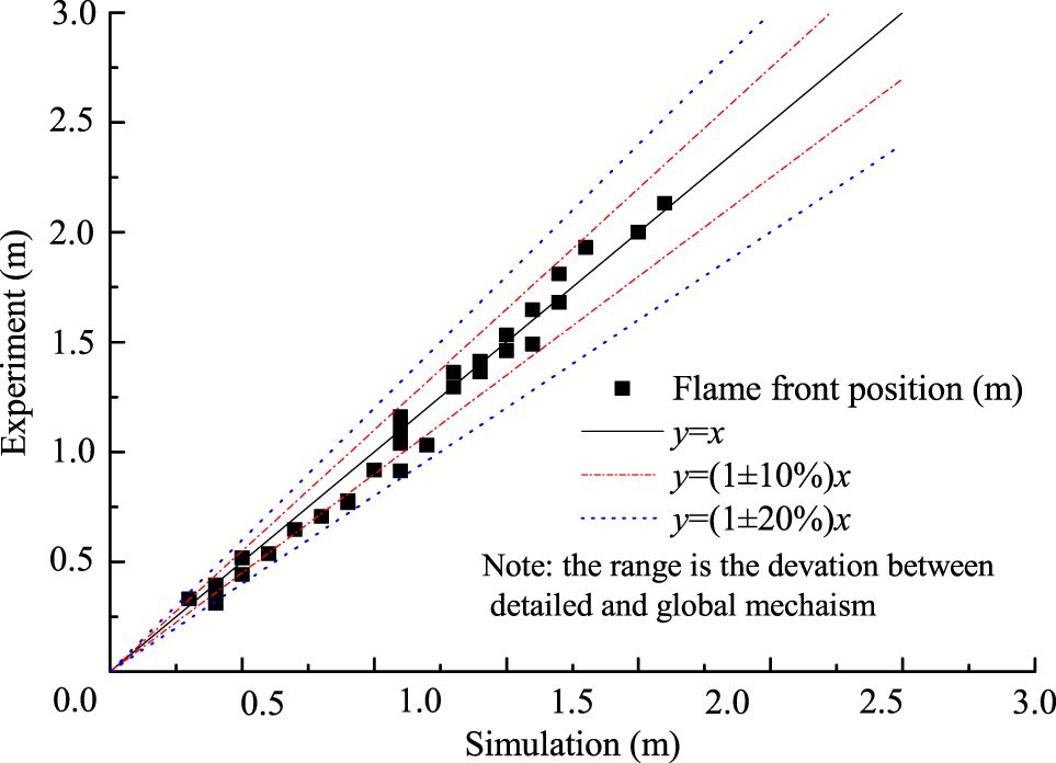
Comparison of flame front positions between updated kinetics and experiments.
The single-step mechanism was further validated by CTF experiment (Whitehouse et al., 1996). Figure 6A shows the predicted results for hydrogen concentration of 12.8% at 0.1 MPa, initially 298.15 K. Figure 6B represents the deviations of flame front positions calculated by the global mechanism and obtained from experiments. It can be observed from Figure 6B that most of the deviations of flame front positions are below 20%. The results show that the global mechanism predicts the published experimental results reasonably well.
Figure 6
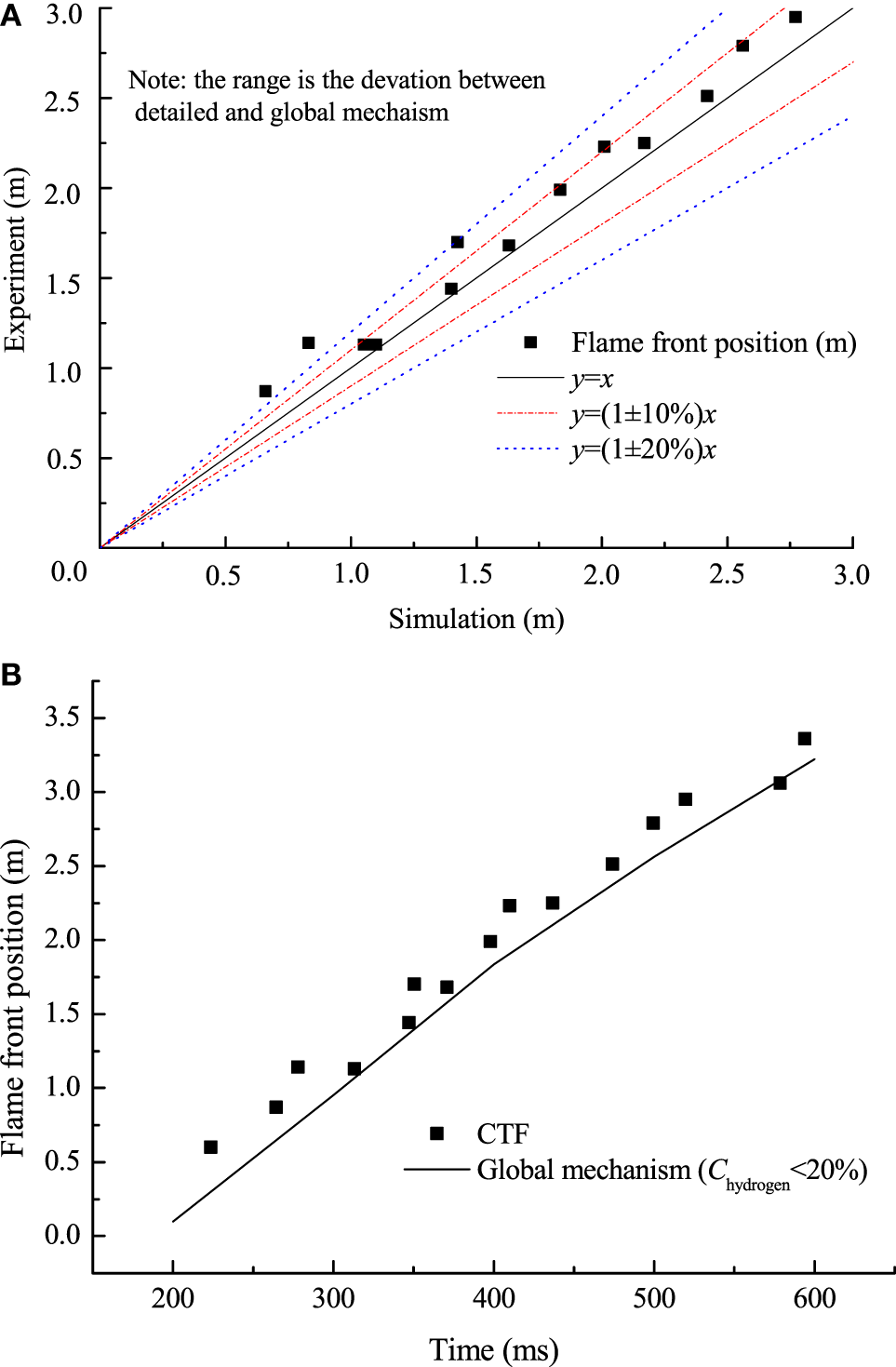
(A) Comparison of flame front position between numerical and published data; (B) comparison of flame front position between updated kinetics and experiments.
The agreements between experimental results obtained both from our container and CTF and numerical simulation were achieved, indicating that the current global model (Chydrogen < 20%) predicts experiments well.
To validate the global mechanism (Chydrogen > 20%), the simulation of flame front positions using the global mechanism versus the detailed model (Marinov et al., 1995) was conducted over a large range of concentrations in the container with the same geometric as Liu’s experiments (Liu et al., 2016). Figure 7 shows the comparison of flame front positions and flame temperature between the global mechanism and detailed model. The predictions with the global model were able to match those using detailed mechanism within 20% error over the range of hydrogen concentration from 20 to 70%.
Figure 7

(A) Comparison between global mechanism and detailed mechanism; (B) flame temperatures calculated by global mechanism and detailed mechanism.
Conclusion
A method based on the thermal theory was established to calculate values of reaction orders, activation energy, and pre-exponential factor of global mechanism over the entire range of concentration, from very lean (12% hydrogen concentration) to very rich (70% hydrogen concentration). This global mechanism (Chydrogen < 20%) was validated by the experiment carried out in a closed lab-scale combustion container and CTF facility. In addition, the predicted results obtained with the global mechanism (Chydrogen > 20%) were compared with that of the prediction with a detailed mechanism. The numerical data with the global mechanism are in good agreement with the results obtained from experiments and the detailed mechanism. These both provide a reasonable proof for the current model and indicate the model can be widely applicable for large-scale and complex structure simulation of hydrogen combustion.
Nomenclature
| Roman Symbols | |
| A 0 | factor of the rate constant [kmol−0.4 m1.2 s−1 or kmol−0.5 m1.5 s−1] |
| C | concentration by volume [%vol.] |
| C 1, C2 | turbulent model constants |
| C p | specific heat capacity at constant pressure [J kg−1 K−1] |
| Di | mass diffusivity coefficient of species i [m2 s−1] |
| E a | activation energy [kcal mol−1 or J mol−1] |
| [H2] | concentration of unreacted hydrogen [mol m−3] |
| [O2] | concentration of unreacted oxygen [mol m−3] |
| Q | Heat conductivity flux [J s−1 m−2] |
| R | universal gas constant [J mol−1 K−1] |
| Ri | net rate of production of species i by chemical reaction in system |
| S L | laminar burning velocity [m s−1] |
| ST | source term of energy conservation equation |
| Su, Sv, Sw | source terms of momentum conservation equation |
| T 0 | initial temperature [K] |
| Ti | ignition temperature [K] |
| Tf | flame temperature [K] |
| a, b | reaction order |
| ci | concentration of species i by volume |
| reaction rate constant for H2 concentration lower than 20% [kmol−0.5 m1.5 s−1] | |
| reaction rate constant for H2 concentration higher than 20% [kmol−0.4 m1.2 s−1] | |
| ṁ | mass flux [kg m−2 s−1] |
| p | pressure [Pa] |
| rk | ignition radius [mm] |
| t | time [s] |
| u, v, w | Favre-averaged velocities [m s−1] |
| w | rate of overall reaction [mol s−1 m−3] |
| [x] | gas concentration of component x |
| Greek Symbols | |
| β | temperature correction coefficient |
| δr | reaction distance in which the temperature rises from Ti to Tf [m] |
| ε | dissipation of turbulent kinetic energy |
| λ | thermal conductivity [W m−1 K−1] |
| μ | dynamic viscosity [Pa s] |
| ρ | density [kg m−3] |
| σk, σε | model constants |
| τr | reaction time [s] |
| Φ | equivalence ratio |
Statements
Author contributions
YL proposed the idea of the paper and cowrote the manuscript. YZ performed the calculation and cowrote the manuscript.
Conflict of interest
The authors declare that the research was conducted in the absence of any commercial or financial relationships that could be construed as a potential conflict of interest.
References
1
Andrews G. Bradley D. (1973). Determination of burning velocity by double ignition in a closed vessel. Combust. Flame20, 77–89.10.1016/S0010-2180(73)81259-3
2
Aung K. T. Hassan M. I. Faeth G. M. (1997). Flame stretch interactions of laminar premixed hydrogen/air flames at normal temperature and pressure. Combust. Flame109, 1–24.10.1016/S0010-2180(96)00151-4
3
Azatyan T. Mal’tsev V. Merzhanov A. Seleznev V. (1979). Some principles of combustion of titanium-silicon mixtures. Combust. Explos. Shock Waves15, 35–40.10.1007/BF00785326
4
Bane S. Ziegler J. Shepherd J. (2010). Development of One-Step Chemistry Models for Flame and Ignition Simulation. GALCIT Report GALTCITFM:2010002. Graduate Aerospace Laboratories, California Institute of Technology, Pasadena.
5
Baraldi D. Heitsch M. Wilkening H. (2007). CFD simulations of hydrogen combustion in a simplified EPR containment with CFX and REACFLOW. Nucl. Eng. Des.237, 1668–1678.10.1016/j.nucengdes.2007.02.026
6
Berman M. (1984). Sandia Laboratories Report, SAND84-0689. Albuquerque.
7
Bhattacharjee B. Schwer D. A. Barton P. I. Green W. H. (2003). Optimally-reduced kinetic models: reaction elimination in large-scale kinetic mechanisms. Combust. Flame135, 191–208.10.1016/S0010-2180(03)00159-7
8
Brad R. Tomlin A. Fairweather M. Griffiths J. (2007). The application of chemical reduction methods to a combustion system exhibiting complex dynamics. Proc. Combust. Inst.31, 455–463.10.1016/j.proci.2006.07.026
9
Chatelier M. L. (1883). Thermal theory. Annales Des Mine.8, 274–377.
10
Egolfopoulos F. Law C. (1990). Chain mechanisms in the overall reaction orders in laminar flame propagation. Combust. Flame80, 7–16.10.1016/0010-2180(90)90049-W
11
Evans M. W. (1952). Current theoretical concepts of steady-state flame propagation. Chem. Rev.51, 363–429.10.1021/cr60160a001
12
Fernández-Galisteo D. Sánchez A. Liñán A. Williams F. (2009). One-step reduced kinetics for lean hydrogen-air deflagration. Combust. Flame156, 985–996.10.1016/j.combustflame.2008.10.009
13
Günther R. Janisch G. (1972). Measurements of burning velocity in a flat flame front. Combust. Flame19, 49–53.10.1016/S0010-2180(72)80085-3
14
Holt J. B. Kingman D. Bianchini G. (1985). Kinetics of the combustion synthesis of TiB2. Mater. Sci. Eng.71, 321–327.10.1016/0025-5416(85)90244-7
15
I.A.E. Agency. (2011). Mitigation of Hydrogen Hazards in Severe Accidents in Nuclear Power Plants. Vienna: I.A.E. Agency.
16
Khaikin B. Merzhanov A. (1966). Theory of thermal propagation of a chemical reaction front. Combust. Explos. Shock Waves2, 22–27.10.1007/BF00749022
17
Kim J. Hong S. W. (2015). Analysis of hydrogen flame acceleration in APR1400 containment by coupling hydrogen distribution and combustion analysis codes. Prog. Nucl. Energy78, 101–109.10.1016/j.pnucene.2014.09.003
18
Kim J. P. Schnell U. Scheffknecht G. (2008). Comparison of different global reaction mechanisms for MILD combustion of natural gas. Combust. Sci. Technol.180, 565–592.10.1080/00102200701838735
19
Kirdyashkin A. Maksimov Y. M. Merzhanov A. (1981). Effects of capillary flow on combustion in a gas-free system. Combust. Explos. Shock Waves17, 591–595.10.1007/BF00784246
20
Koroll G. Kumar R. Bowles E. (1993). Burning velocities of hydrogen-air mixtures. Combust. Flame94, 330–340.10.1016/0010-2180(93)90078-H
21
Kuo K. K. (2005). Principles and Combustion. USA: Wiley.
22
Law C. K. (2006). Combustion Physics. New York: Cambridge University Press.
23
Liu D. MacFarlane R. (1983). Laminar burning velocities of hydrogen-air and hydrogen-air steam flames. Combust. Flame49, 59–71.10.1016/0010-2180(83)90151-7
24
Liu Y. Zhang Y. Liu X. Liu Z. Che D. (2016). Experimental and numerical investigation on premixed H2/air combustion. Int. J. Hydrogen Energy41, 10496–10506.10.1016/j.ijhydene.2016.01.049
25
Lu T. Law C. K. (2005). A directed relation graph method for mechanism reduction. Proc. Combust. Inst.30, 1333–1341.10.1016/j.proci.2004.08.145
26
Lu T. Law C. K. (2009). Toward accommodating realistic fuel chemistry in large-scale computations. Prog. Energy Combust. Sci.35, 192–215.10.1016/j.pecs.2008.10.002
27
Manninen M. Silde A. Lindholm I. Huhtanen R. Sjovall H. (2002). Simulation of hydrogen deflagration and detonation in a BWR reactor building. Nucl. Eng. Des.211, 27–50.10.1016/S0029-5493(01)00443-5
28
Marinov N. M. Westbrook C. K. Pitz W. J. (1995). “Detailed and global chemical kinetics model for hydrogen,” in 8th International Symposium on Transport Properties (San Francisco, CA: Taylor & Francis), 118–129.
29
Merzhanov A. Borovinskaya I. Volodin Y. E. (1972). “Mechanism of combustion for porous metal specimens in nitrogen,” in Dokl Akad Nauk SSSR, 905–908.
30
Momirlan M. Veziroglu T. N. (2005). The properties of hydrogen as fuel tomorrow in sustainable energy system for a cleaner planet. Int. J. Hydrogen Energy30, 795–802.10.1016/j.ijhydene.2004.10.011
31
San Marchi C. Hecht E. S. Ekoto I. W. Groth K. M. LaFleur C. Somerday B. P. et al (2015). “Advances in research and development to enhance the scientific basis for hydrogen regulations, codes and standards,” in 6th International Conference on Hydrogen Safety (ICHS) (Yokohama, Japan).
32
Sung C. J. Law C. K. Chen J. Y. (2001). Augmented reduced mechanisms for NO emission in methane oxidation. Combust. Flame125, 906–919.10.1016/S0010-2180(00)00248-0
33
Wang C. Wen J. Lu S. Guo J. (2012). Single-step chemistry model and transport coefficient model for hydrogen combustion. Sci. Chin. Technol. Sci.55, 2163–2168.10.1007/s11431-012-4932-4
34
Whitehouse D. R. Greig D. R. Koroll G. W. (1996). Combustion of stratified hydrogen-air mixtures in the 10.7 m3 combustion test facility cylinder. Nucl. Eng. Des.166, 453–462.10.1016/S0029-5493(96)01261-7
35
Xiao H. Makarov D. Sun J. Molkov V. (2012). Experimental and numerical investigation of premixed flame propagation with distorted tulip shape in a closed duct. Combust. Flame159, 1523–1538.10.1016/j.combustflame.2011.12.003
36
Yanez J. Kuznetsov M. Souto-Iglesias A. (2015). An analysis of the hydrogen explosion in the Fukushima-Daiichi accident. Int. J. Hydrogen Energy40, 8261–8280.10.1016/j.ijhydene.2015.03.154
Summary
Keywords
hydrogen combustion, global reaction mechanism, kinetic parameter, thermal theory, numerical simulation
Citation
Zhang Y and Liu Y (2017) Numerical Simulation of Hydrogen Combustion: Global Reaction Model and Validation. Front. Energy Res. 5:31. doi: 10.3389/fenrg.2017.00031
Received
09 July 2017
Accepted
31 October 2017
Published
20 November 2017
Volume
5 - 2017
Edited by
Bruno Panella, Politecnico di Torino, Italy
Reviewed by
Qiang Tang, Central Queensland University, Australia; Marco Nicola Carcassi, University of Pisa, Italy
Updates
Copyright
© 2017 Zhang and Liu.
This is an open-access article distributed under the terms of the Creative Commons Attribution License (CC BY). The use, distribution or reproduction in other forums is permitted, provided the original author(s) or licensor are credited and that the original publication in this journal is cited, in accordance with accepted academic practice. No use, distribution or reproduction is permitted which does not comply with these terms.
*Correspondence: Yinhe Liu, yinheliu@mail.xjtu.edu.cn
Specialty section: This article was submitted to Nuclear Energy, a section of the journal Frontiers in Energy Research
Disclaimer
All claims expressed in this article are solely those of the authors and do not necessarily represent those of their affiliated organizations, or those of the publisher, the editors and the reviewers. Any product that may be evaluated in this article or claim that may be made by its manufacturer is not guaranteed or endorsed by the publisher.