Abstract
Lithium metal is a promising anode material for next-generation rechargeable batteries, but non-uniform electrodeposition of lithium is a significant barrier. These non-uniform deposits are often referred to as lithium “dendrites,” although their morphologies can vary. We have surveyed the literature on lithium electrodeposition through three classes of electrolytes: liquids, polymers and inorganic solids. We find that the non-uniform deposits can be grouped into six classes: whiskers, moss, dendrites, globules, trees, and cracks. These deposits were obtained in a variety of cell geometries using both unidirectional deposition and cell cycling. The main result of the study is a figure where the morphology of electrodeposited lithium is plotted as a function of two variables: shear modulus of the electrolyte and current density normalized by the limiting current density. We show that specific morphologies are confined to contiguous regions on this two-dimensional plot.
Introduction
There is growing interest in the nature of electrodeposition at lithium metal electrodes due to the current focus on increasing the energy density of rechargeable lithium batteries (Girishkumar et al., 2010; Balsara and Newman, 2013). However, many fundamental challenges must be addressed before lithium electrodes can be deployed in practical devices (Aurbach et al., 2000, 2002). One of the main challenges is the nucleation and growth of protrusions during battery charging (Selim and Bro, 1974; Besenhard and Eichinger, 1976; Epelboin, 2006), which limits the battery lifetime and compromises safety (Yamaki et al., 1998; Aurbach et al., 2002). These protrusions are often referred to as “lithium dendrites.” Strictly, the word “dendrite” implies a branched structure; we propose to not use this term as many non-dendritic morphologies have been reported in the literature.
Lithium metal protrusions have been observed in electrodeposition and cycling experiments conducted in a wide array of electrolytes (Arakawa et al., 1993; Brissot et al., 1998; Ren et al., 2015). We focus on three classes of electrolytes: those based on organic liquids, organic polymers, and inorganic solids. The lithium ions are present in both liquid- and polymer-based electrolytes due to the addition of a suitable salt. In contrast, lithium ions are an integral part of the crystal structure of inorganic solid electrolytes. The passage of current results in salt concentration gradients in liquid-and polymer-based electrolytes (Chazalviel, 1990). On the other hand, these concentration gradients are absent when current flows through inorganic solid electrolytes. In principle, polymer electrolytes can also be single ion conductors if the anion is covalently linked to the polymer chain (Bouchet et al., 2013). Compared to polymer electrolytes with added salt, there is little information about dendrite morphologies obtained in polymeric single-ion conductors (Cao et al., 2019; Dai et al., 2019). We have thus chosen to only discuss liquid and polymer electrolyte systems with added salt. Our objective is to identify the parameters that control the nature of lithium electrodeposition in liquid electrolytes, polymer electrolytes, and ceramic electrolytes.
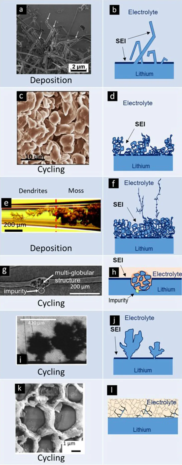
The morphology of electrodeposited lithium is affected by many factors, such as current density, salt concentration where lithium is plating, tip radius of the protrusion, temperature, pressure (Yamaki et al., 1998; Gireaud et al., 2006) solid electrolyte interphase (SEI), and the ion transport and mechanical properties of electrolyte (Barton and Bockris, 1961; Diggle et al., 1969; Jana and García, 2017). While we have focused on the anode and the electrolyte, it is well-known that spontaneous reactions between lithium metal and all known electrolytes result in the formation of an SEI layer (Peled, 1979), which plays a central role in stable cycling (Tarascon and Armand, 2001; Meyerson et al., 2019). We have also glossed over the fact that liquid electrolytes are often contained within porous separators that are necessary for battery operation. The observed morphologies are grouped in six different classes described in Table 1. Important features of the lithium morphology are summarized in Table 2.
Table 1
| Morphology | Image | Schematic |
|---|---|---|
| Whiskers |
|
|
| Moss | ||
| Dendrites | ||
| Globules | ||
| Trees | ||
| Cracks | ||
Name, experimental visualization, and schematic of common morphologies of electrodeposited lithium. Images of whiskers, mosses, dendrites, globules, trees, and cracks are reproduced with permission from (a) Steiger et al. (2014), (b) Qian et al. (2015), (c) Bai et al. (2016), (d) Harry et al. (2015), (e) Brissot et al. (1998), and (f) Cheng et al. (2017).
Table 2
| Name | Description | Width (μm) | Height (μm) | Aspect ratio (length/width) |
|---|---|---|---|---|
| Whiskers | Objects with minimal branching and kinks surrounded by excess electrolyte | 0.1–5 | 10–100 | 100 |
| Moss | Interconnected pebble-like objects with electrolyte within gaps and pores | 10–50 | – | 1 |
| Dendrites | Branched, fractal structures | 1–20 | 100–600 | 10 |
| Globules | Collections of compact globules nucleated on an impurity particle | 20–150 | 20–150 | 1–2 |
| Trees | Object with a narrow stem and a branched top | At the bottom 10–50 At the top 50–500 | 100–500 | 1–3 |
| Cracks | Object growing through grain boundaries or structural weakness in the inorganic solid electrolyte | 1 | – | 5 |
Name, description, characteristic width, and aspect ratio of electrodeposited lithium morphologies.
Whiskers emanating from the anode represent the simplest morphology of lithium protrusions. These are generally long and thin structures, with widths of about 1 μm and lengths ranging from 10 to 100 μm (see first entry in Table 2). Panel a in Table 1 shows a scanning electron microscopy (SEM) image of whiskers. A schematic of whiskers is shown next to the SEM image in Panel b (Table 1). In this schematic, we represent the whiskers connected directly to the anode without an intervening SEI layer (Aurbach et al., 2002). We hypothesize that this must be the case; we are not aware of any direct support for our hypothesis. The whiskers are covered by an SEI layer (Peled, 1979; Aurbach et al., 1987) and surrounded by the electrolyte. Panel c in Table 1 shows an SEM image of mossy lithium and a schematic of this morphology is shown in Panel d (Table 1). This electrodeposited lithium presents solid interconnected pebbles with electrolyte filling gaps and pores. Panels e,f in Table 1 present lithium dendrites. Dendrites are thin-branched, fractal objects. Lithium globules are presented in Panels g,h (Table 1). These objects are found in confined regions, unlike whiskers, mosses and dendrites which tend to form across the entire electrode. Globules are nucleated at an impurity particle in the electrode. Panels i,j in Table 1, show lithium trees emanating from the electrode. Unlike mosses that are irregular in shape, the lateral size of trees increases with increasing distance from the electrode. Panels k,l in Table 1 show lithium deposition through cracks in ceramic electrolytes. In this case, lithium protrusions grow through grain boundaries and result in cracking of the electrolyte. Typical sizes and aspect ratios of the protrusions described above are given in Table 2.
There have been many attempts to model the growth of metallic protrusions during electrodeposition from different electrolytes (Barton and Bockris, 1961; Diggle et al., 1969; Monroe and Newman, 2005; Voss and Tomkiewicz, 2006; Mayers et al., 2012). In the case of liquid- and polymer-based electrolytes, the passage of current results in depletion of salt at the cathode where lithium is being deposited. The current density, i, at which the salt concentration at the cathode approaches zero is defined as the limiting current density, iL. The depletion of salt has been implicated in lithium protrusion nucleation and growth (Chazalviel, 1990; Bai et al., 2016). However, lithium protrusions have been observed to nucleate and grow at current densities far below the limiting current (Rosso et al., 2001; Xu et al., 2014; Jana and García, 2017). The nucleation and growth of lithium protrusions is also affected by the modulus and other mechanical properties of the electrolyte (Monroe and Newman, 2003, 2005; Barai et al., 2017). The importance of limiting current has been recognized in the literature (Chazalviel, 1990; Bai et al., 2016; Barai et al., 2017; Maslyn et al., 2018).
In this review, we demonstrate that the lithium protrusion morphology obtained in different classes of electrolytes are mainly functions of two parameters: (1) current density normalized by the limiting current density and (2) modulus of the electrolyte. We present literature results for lithium protrusion morphology as a function of these two parameters on a “morphology diagram.” Each morphology is roughly restricted to contiguous regions on this diagram.
Methods
The classes of electrolytes covered in this review are given in Table 3. The first column in Table 3 provides a description of these classes and gives typical examples. The second column describes the mechanical behavior of the electrolyte. The liquid and inorganic solid electrolytes are relatively simple from the mechanical point of view. Polymers on the other hand are neither simple solids nor simple liquids. They exhibit both viscous and elastic properties depending on temperature and time-scale of observation. Additionally, Table 3 includes the orders of magnitude of relevant electrochemical properties: conductivity, κ, salt diffusion coefficient, D, and steady-state current ratio, ρ+. Conductivity is measured by ac impedance, salt diffusion coefficient is measured by restricted diffusion, and the steady-state current ratio is measured in lithium-lithium symmetric cells.
Table 3
| Electrolyte | Description | Mechanical behavior | Order of magnitude of κ [S.cm−1] | Order of magnitude of D [cm2.s−1] | Order of magnitude of ρ+ |
|---|---|---|---|---|---|
| Liquid | Salt dissolved in traditional carbonate-based liquid electrolyte (e.g., EC, PC, DMC) | viscous | 10−2 | 10−6 | 0.3–0.4 |
| Polymer | Salt dissolved in a neutral polymer (e.g., PEO, SEO) | elastic | 10−4–10−3 | 10−8–10−7 | 0.05–0.2 |
| Inorganic solid | Solid ceramic with lithium ions in the lattice (e.g., LLZO) | solid | 10−4 | – | 1 |
The three categories of electrolytes covered in this review, with their description, order of magnitude of ionic conductivity, κ, order of magnitude of the salt diffusion coefficient, D, characteristic range of steady-state current fraction, ρ+, and characteristic mechanical behavior at the temperature of interest.
The steady-state current fraction deserves some clarification. This approach for characterization of electrolytes was pioneered by Bruce, Vincent, and Evans (Bruce and Vincent, 1987; Evans et al., 1987). In this approach, a fixed dc potential is applied to the symmetric cell and current is recorded as a function of time. At early times, the salt concentration in the electrolyte is uniform (as it is when the cell is at rest) and the current obtained under these circumstances is dictated by conductivity alone. We ignore contribution from interfacial impedance in this description; this is discussed extensively in the literature (Bruce and Vincent, 1987; Evans et al., 1987). We refer to the current obtained in the absence of concentration gradient as iΩ. The passage of time results in the establishment of salt concentration gradients, which, in turn, lead to a reduction of current. The ratio of the final steady-state current obtained in such an experiment, iSS, to iΩ is defined as the steady-state current fraction ρ+ (Gray and Bruce, 1995; Galluzzo et al., 2019). In the literature this fraction is often called the transference number, t+. It is known however that ρ+ equals t+ for the case of dilute electrolytes that are thermodynamically ideal (i.e., when the salt activity coefficient is unity). Since practical electrolytes are never dilute, it is our understanding that the transference number is different from ρ+ in all of the electrolytes covered in this study. Nevertheless, the steady-state current fraction is an important characteristic of electrolytes. The analysis presented in this paper makes extensive use of this characteristic.
Discussion
The systems chosen for this study are listed in Table 4. Each class of electrolytes is presented using a different color background: blue for liquid electrolytes listed first, red for polymer electrolytes listed second, and yellow for inorganic solid electrolytes listed third. The liquid electrolytes are alkyl-carbonate-based systems used in lithium-ion batteries. The alkyl carbonates of interest include ethylene carbonate (EC), dimethyl carbonate (DMC), diethylene carbonate (DEC), and propylene carbonate (PC). The salts dissolved in these liquids include bis (trifluoromethanesulfonyl)imide lithium salt (LiTFSI), lithium perchlorate (LiClO4), and lithium hexafluorophosphate (LiPF6). The second class is polymer electrolytes, which are composed of a neutral polymer, such as poly(ethylene oxide) (PEO) or block copolymer poly(styrene)-b-poly(ethylene oxide) (SEO). The salt dissolved in these polymers is usually LiTFSI or lithium bis(fluorosulfonyl)imide (LiFSI). The last class is inorganic solid electrolytes, which can be either classical crystalline solids with lithium ions in the lattice, such as Li7La3Zr2O12 (LLZO) or glassy solids, such as 80Li2S-20P2S5.
Table 4
| Electrolyte | G' (Pa) | cb(mol.L−1) | κ (S.cm−1) | D (cm2.s−1) | ρ+ | L (cm) | i (mA.cm−2) | iL(mA.cm−2) | Type of cell used | Cycling/Deposition | References |
|---|---|---|---|---|---|---|---|---|---|---|---|
| LiPF6 EC:DMC ratio 1:1 | – | 1 | 1.0 × 10⁻² Dahbi et al., 2011 | 2.5 × 10⁻⁶ Valøen and Reimers, 2005 | 0.39 Valøen and Reimers, 2005 | 0.1 | 1 | 8 | Li/Li and Li/graphite | C | Kim and Yoon, 2004 |
| LiPF6 EC:DMC ratio 1:1 | – | 1 | 1.0 × 10⁻² Dahbi et al., 2011 | 1.0 × 10⁻⁶ | 0.38 | 0.03 | 1.09 to 50 | 20 | Li/Li | D | Bai et al., 2016 |
| 0.5 | 1 | ||||||||||
| LiPF6 PC:DMC ratio 1:3 | – | 1 | 1.0 × 10⁻² Dahbi et al., 2011 | 2.5 × 10⁻⁶ Valøen and Reimers, 2005 | 0.39 Valøen and Reimers, 2005 | 0.013 | 4 | 120 | Li/Cu | D | Crowther and West, 2008 |
| 0.010 | 162 | ||||||||||
| LiPF6 EC:EMC ratio 3:7 | – | 1.2 | 1.0 × 10⁻² Dahbi et al., 2011 | 2.5 × 10⁻⁶ Valøen and Reimers, 2005 | 0.39 Valøen and Reimers, 2005 | 0.0025 | 2 | 380 | Li/Li4Ti5O12 | C | López et al., 2009 |
| LiClO4 in PC | – | 0.25 | 5.4 × 10⁻³ Werblan and Bałkowska, 1993 | 2.2 × 10⁻⁶ Nishikawa et al., 2006 | 0.29 Mauro et al., 2005 | 0.0025 | 5 | 75 | Li/Ni | D | Nishikawa et al., 2010 |
| – | 1 | 1.3 × 10⁻⁶ Nishikawa et al., 2006 | 5 | 177 | |||||||
| LiPF6 EC:DMC ratio 1:1 | – | 1 | 1.0 × 10⁻² Dahbi et al., 2011 | 2.5 × 10⁻⁶ Valøen and Reimers, 2005 | 0.39 Valøen and Reimers, 2005 | 0.0025 | 0.5 | 316 | Li/Cu and Li-LiF/Cu | D | Zhang et al., 2017 |
| LiPF6 EC:DMC ratio 1:1 | – | 1 | 1.0 × 10⁻² Dahbi et al., 2011 | 2.5 × 10⁻⁶ Valøen and Reimers, 2005 | 0.39 Valøen and Reimers, 2005 | 0.0025 | 0.74 to 0.2 | 316 | Li/Cu and Li/W | D | Steiger et al., 2014, 2015 |
| LiPF6 in EC:EMC | – | 1 | 1.0 × 10⁻² Dahbi et al., 2011 | 2.5 × 10⁻⁶ Valøen and Reimers, 2005 | 0.39 Valøen and Reimers, 2005 | 0.0025 | 0.3 | 316 | Li/Li and Li/SiC | C | Sun et al., 2016 |
| (LiPF6), (LiTFSI), or LiFSI in DME, or DOL and PC | – | 1 | 1.0 × 10⁻² Dahbi et al., 2011 | 2.5 × 10⁻⁶ Valøen and Reimers, 2005 | 0.39 Valøen and Reimers, 2005 | 0.0025 | 0.2 to 8 | 316 | Li/Li and Li/Cu | C | Qian et al., 2015 |
| LiPF6 in EC:DEC | – | 1 | 1.0 × 10⁻² Dahbi et al., 2011 | 2.5 × 10⁻⁶ Valøen and Reimers, 2005 | 0.39 Valøen and Reimers, 2005 | 0.0015 | 0.5 | 527 | Li/Li and Li/graphene sheet | C | Bobnar et al., 2018 |
| LiPF6 EC:DMC ratio 1:1 | – | 1 | 1.0 × 10⁻² Dahbi et al., 2011 | 2.5 × 10⁻⁶ Valøen and Reimers, 2005 | 0.39 Valøen and Reimers, 2005 | 0.0025 | 1 | 316 | Li/Li | D | Zachman et al., 2018 |
| LiPF6 EC:DMC ratio 1:1 | – | 1 | 1.0 × 10⁻² Dahbi et al., 2011 | 2.5 × 10⁻⁶ Valøen and Reimers, 2005 | 0.39 Valøen and Reimers, 2005 | 0.2 | 0.64 | 395 | Li/Li | C | Eastwood et al., 2015 |
| LiPF6 or LiTFSI EC:DMC or EC:PC ratio 1:1 | – | 1 | 1.0 × 10⁻² Dahbi et al., 2011 | 2.5 × 10⁻⁶ Valøen and Reimers, 2005 | 0.39 Valøen and Reimers, 2005 | 0.0695 | 1 to 50 | 11.4 | Li/Li | D | Gireaud et al., 2006 |
| LiTFSI and SEO (240–260) | 108 Harry et al., 2014 | 1.59 | 5.5 × 10⁻⁴ Villaluenga et al., 2018 | 4.70 × 10⁻⁸ Villaluenga et al., 2018 | 0.05 Pesko et al., 2018 | 0.003 | 0.175 | 4 | Li/Li | C at 90°C | Harry et al., 2014, 2015, 2016; Schauser et al., 2014 |
| LiTFSI and PEO 30 | 103 Stone et al., 2012 | 0.095 | 1.5 × 10⁻³ Pesko et al., 2018 | 3.5 × 10⁻⁸ Pesko et al., 2018 | 0.085 Pesko et al., 2018 | 0.2 | 0.1 to 0.5 | 0.0035 | Li/Li and Li/Cu | C at 90°C | Dollé et al., 2002 |
| LiTFSI and PEO 300 | 108 Stone et al., 2012 | 0.095 | 1.5 × 10⁻³ Pesko et al., 2018 | 6.00 × 10⁻⁸ Pesko et al., 2018 | 0.085 Pesko et al., 2018 | 0.0035 | 0.06 | 0.343 | Li/Li | D at 90°C | Rosso et al., 2006 |
| 0.01 | 0.06 | 0.12 | |||||||||
| 0.1 | 0.06 | 0.0012 | |||||||||
| LiTFSI and PEO 30 | 103 Stone et al., 2012 | 0.095 | 9.7 × 10⁻⁴ | 3.5 × 10⁻⁸ Pesko et al., 2018 | 0.085 Pesko et al., 2018 | 0.2 | 0.2 | 4 | Li/Li | C at 80°C | Brissot et al., 1998 |
| LiTFSI and PEO 60 | 103 Stone et al., 2012 | 0.95 | 1.0 × 10⁻⁵ | 6.00 × 10⁻⁸ Pesko et al., 2018 | 0.085 Pesko et al., 2018 | 0.02 | 0.05 | 0.6 | Li/Li | D | Hirano, 2010 |
| LiTFSI and SEO (115–172) | 108 Harry et al., 2014 | 1.59 | 5.5 × 10⁻⁴ | 7.37 × 10⁻⁸ | 0.045 Pesko et al., 2018 | 0.004 | 0.02 to 0.64 | 4 | Li/Li | D at 90°C | Maslyn et al., 2018 |
| LiTFSI and PEO 30 | 103 Stone et al., 2012 | 0.095 | 9.1 × 10⁻⁴ Pesko et al., 2018 | 3.50 × 10⁻⁸ Pesko et al., 2018 | 0.085 Pesko et al., 2018 | 0.1 | 0.95 | 0.007 | Li/Li | D at 80°C | Brissot et al., 1999, 2001 |
| β-Li3PS4 | 1012 Baranowski et al., 2016 | – | 1.6 × 10⁻⁴ Liu et al., 2013 | – | 1 | 0.3 | 0.01 to 5 | – | Li/Li | C/D | Porz et al., 2017; Seitzman et al., 2018 |
| LLZO | 5 × 10¹⁰ | – | 2.0 × 10⁻⁴ Shao et al., 2016 | – | 1 | 0.015 to 0.50 | – | Li/Li | C/D/C | Ren et al., 2015; Cheng et al., 2017; Porz et al., 2017) | |
| 80Li2S-20P2S5 | 2 × 10¹⁰ Kato et al., 2018 | – | 2.8 × 10⁻⁴ Sakuda et al., 2010 | – | 1 | 0.05 to 20 | – | Li/Li | C | Nagao et al., 2013 |
Properties of electrolytes and cells used to study lithium electrodeposition covered in this review.
We report shear modulus, G', the ionic conductivity, κ, diffusion coefficient, D, the current ratio, ρ+ number or best estimated transference number, the applied current density, i, the measured or calculated limiting current, iL, the distance between the electrodes, L, the type of cell cycled, if the lithium was unidirectional electrodeposited (D) or cycled (C) and the reference. The number next to the polymer electrolytes refers to the number averaged molecular weight of the polymer in kg.mol−1.
The importance of limiting current has already been discussed above. However, this parameter is seldom measured directly by experiment. We thus use a simple expression for the limiting current taken from (Monroe and Newman, 2003),
where cb is the salt concentration in the conducting phase, F is the Faraday's constant, and L is the distance between the two electrodes. We have taken the liberty of replacing the transference number in equation (23.5) in Monroe and Newman (2003) by ρ+. Equation 1 only applies to electrolytes containing added salt. It does not apply to single ion conductors.
In Table 4, we provide values for the parameters required to calculate iL. For completeness we provide values for conductivity, though this parameter is not used in our analysis. The first entry in Table 4 is the classical lithium-ion battery electrolyte. The formation of lithium protrusions in this electrolyte was studied using two different kind of cells: lithium-lithium symmetric cells and a half cell with carbon as the cathode. Protrusions were obtained after cycling the cells, indicated in the cycling/deposition column by ‘C'. The electrochemical parameters were obtained from references (Valøen and Reimers, 2005; Dahbi et al., 2011) as indicated in the first entry in Table 4. In many of the entries in Table 4, electrochemical characterization data was obtained from different references, as is the case for the first entry. In such cases, the reference is provided below the parameter. In cases where electrochemical characterization data were presented along with lithium protrusion characterization, no references are provided next to the characterization data. The parameter L, is the distance between the electrodes. In the case of composite cathodes like the carbon (graphite particles) used in the first entry, we ignore salt concentration gradients that occur within the electrolyte contained inside the pores of the composite cathode. In addition, when the cell has two different electrodes, one of the electrodes is always lithium metal and we are only concerned with electrodeposition of lithium on the lithium metal electrode. The second entry in Table 4 is similar to the first entry except that the cell was not cycled. The formation of lithium protrusion was studied after one-directional electrodeposition, indicated in the cycling/deposition column by ‘D'. In the third entry in Table 4, the copper cathode is electrochemically inactive. Lithium metal is deposited onto this cathode, which is similar to a lithium metal electrode after sufficient passage of current. Other entries related to liquid electrolytes in Table 4 include surfaces treated with specific chemicals [e.g., copper treated with lithium fluoride (LiF) and lithium treated with silicon carbide (SiC)]. A majority of the liquid electrolytes studies reported in Table 4 were conducted on lithium-lithium symmetric cells.
In many systems reported in Table 4, the parameters needed to estimate iL were not reported in the lithium electrodeposition studies. We have relied on literature to estimate parameters in these cases. The deposition experiments for liquid electrolytes were conducted in the vicinity of room temperature (20°C to 30°C). We have not accounted for temperature variation between different studies. The values of iL reported in Table 4 vary from 0.06 to 380 mA.cm−2. While many parameters affect iL, the wide range of iL values are largely due to differences in L (see Equation 1). We posit that the differences in mechanical properties of liquid electrolytes are small, and therefore not relevant. We thus do not report the modulus of these systems in Table 4.
The work on lithium electrodeposition through polymers is restricted to PEO homopolymers and PEO containing block copolymers. The electrodeposition experiments are conducted at elevated temperatures (e.g., 90°C), due to poor ion transport in the vicinity of room temperature. The electrochemical parameters reported in Table 4 are applicable at the temperature at which the electrodeposition was performed. In polymer electrolytes the values of iL range from 0.001 to 4 mA.cm−2. The in-phase shear modulus, G', of the polymers in the low frequency limit is also reported in Table 4. At the temperatures of interest, PEO homopolymers are rubbery liquids and in the low frequency limit G' is proportional to ω2, where ω is the frequency. In other words, the shear modulus of PEO homopolymer is negligible at low frequencies. On the other hand, SEO block copolymers exhibit a frequency independent G' in the low frequency limit. This solid-like behavior is due to the presence of the glassy polystyrene domains. The values of G' reported for these systems is thus non-negligible.
The last set of entries in Table 4 pertain to inorganic solid electrolytes. In these systems Li+ is the only mobile ion and thus ρ+ = 1. The limiting current in these systems cannot be calculated using Equation (1) (Monroe and Newman, 2003). The shear moduli of these materials are 4 orders of magnitudes larger than those of polymeric solids in Table 4.
There are many studies of lithium protrusion morphology in novel electrolytes such as ionic liquids and organic-inorganic composite electrolytes. We do not include them due to the unavailability of the necessary electrochemical characterization data.
Since theory suggests that the limiting current plays an important role (Chazalviel, 1990; Monroe and Newman, 2003; Bai et al., 2016; Barai et al., 2017; Maslyn et al., 2018), we define a normalized current density as the experimental current density over the limiting current density.
Where i is the applied current density.
In Figure 1, we present results of lithium electrodeposition experiments that were listed in Table 4. The modulus of the electrolytes is given on the abscissa and the normalized current density is given on the ordinate. A red dashed line indicates where the applied current density to the cell equals the limiting current. All of the protrusion morphologies listed in Table 1 occupy contiguous regions in Figure 1 and are shaded in different colors with the corresponding cartoon for visual clarity. The vertical dashed lines in the figure distinguish the three different kinds of electrolytes considered in this review (Table 3):
-
Liquids. In liquid electrolytes with negligible moduli, whiskers (green) are obtained in the regime inorm = 10−7. At this low normalized current density, the driving force for lithium ion reduction is not sufficient to induce branching in the projecting structures. It is important to note that in this particular study, lithium electrodeposition was carried out without a separator. Increasing inorm in liquid electrolytes results in the formation of mossy lithium (blue). This morphology is obtained in the range 10−3 < inorm < 7 × 10⁻². In most studies mossy lithium was observed in coin cells where the electrolyte is contained in a porous separator. The spring in the coin cell does exert pressure on the cell components including the interface between lithium metal and the porous separator. It is possible that the mossy lithium seen at low values of inorm are compacted whiskers due to the pressure exerted on them by the separator. Some evidence for this is presented below. Increasing inorm to 0.08 results in coexistence of mossy and whiskers (hatched green and blue). Further increase of inorm to 0.3 results in dendrites that grow on the top of the mossy deposit (hatched gray and blue). The cross-over from mossy to dendritic deposits occurs over a range of inorm values, from 0.08 to 0.3. In this regime we see two isolated pockets: one where moss and whiskers coexist and one where only moss is observed (see Figure 1). There are no examples in Table 4 where lithium dendrites are seen to grow directly from the planar anode.
-
Polymers. Low modulus polymers (G' <10 Pa) exhibit behavior similar to liquids at low values of inorm. At inorm = 0.001, whiskers are seen in a cell that does not contain a separator. Note that at this value of inorm, mossy lithium deposits have been observed in liquid cells with separator (see Figure 1). This suggests that some of the mossy deposits seen in liquid electrolytes may be due to the pressure exerted by the separator. Increasing inorm to 0.01 results in the formation of moss, which is seen in the range between 0.01 and 0.04. At higher normalized current densities, coexisting moss/dendrites are seen. With higher modulus polymers (G' = 103 Pa) and higher normalized current densities, coexisting moss/whiskers are seen for 0.02 < inorm < 0.05. At higher normalized current densities, inorm ≥ 0.2 trees are observed (orange). Increasing the modulus of polymers to 108 Pa results in stable lithium deposition at inorm = 0.005. While the current used under these conditions are too low for practical applications, it is important to note that whiskers are obtained at the same normalized current density in both liquids and polymers with G' < 10 Pa. Increasing inorm to 0.01 results in the formation of globular protrusions. This morphology is seen up to inorm = 0.2.
-
Inorganic solids. The three inorganic solid electrolytes in Table 4 include crystal and glassy solids. In all cases failure due to the passage of current induces cracking (yellow) in the electrolyte. While lithium protrusions grow through grain boundaries in crystals, it is postulated that they grow through mechanically weak portions of glasses. In a recent study it was shown that grain boundaries in crystalline lithium ion conductors exhibit higher electronic conductivity than the bulk crystal (Han et al., 2019). This is one explanation for the observation of the growth of lithium protrusion in grain boundaries.
Figure 1
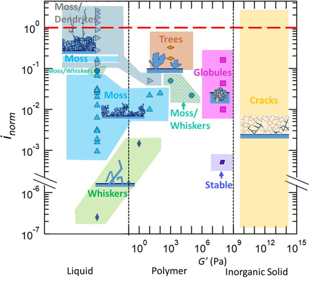
Morphology data of lithium protrusions plotted as a function of the current density normalized by the limiting current density, inorm, vs. the electrolyte type and storage shear modulus, G'. Continuous regions of morphologies are shaded with a solid color, and coexisting morphologies are denoted by hatched regions. The references from where the information is obtained is in Supporting Information, Supplementary Figure 1.
Conclusion
We have surveyed the literature on electrodeposition of lithium through a variety of electrolytes: liquids, polymers, and inorganic solids. We have focused on the morphology of lithium protrusions that often emerged in these experiments. We show that these morphologies are governed by two parameters: shear modulus of the electrolyte and current density normalized by the limiting current density. The main result of this work is Figure 1 where we plot the lithium protrusion morphology as a function of these two parameters. The different morphologies appear in contiguous regions in this figure, analogous to a phase diagram.
Statements
Author contributions
LF, GS, and JM compiled information from the literature. LF, GS, JM, and NB wrote the manuscript.
Acknowledgments
Funding to support this work was provided by the Energy & Biosciences Institute through the EBI-Shell program. LF was supported by EBI-Shell. JM, GS, and NB were supported by the Assistant Secretary for Energy Efficiency and Renewable Energy, Office of Vehicle Technologies of the U.S. Department of Energy under Contract DE-AC02-05CH11231 under the Battery Materials Research Program. GS and JM also acknowledge funding from a National Science Foundation Graduate Student Research Fellowship (2016218210 and DGE 2752814, respectively).
Conflict of interest
The authors declare that the research was conducted in the absence of any commercial or financial relationships that could be construed as a potential conflict of interest.
Supplementary material
The Supplementary Material for this article can be found online at: https://www.frontiersin.org/articles/10.3389/fenrg.2019.00115/full#supplementary-material
- DEC
Diethyl carbonate
- DMC
Dimethyl carbonate
- EC
Ethylene carbonate
- Li
Lithium metal electrode
- LiClO4
Lithium perchlorate
- LiF
Lithium fluoride
- LiFSI
Lithium bis(fluorosulfonyl)imide
- LiPF6
Lithium hexafluorophosphate
- LiTFSI
Lithium bis (trifluoromethanesulfonyl) imide
- LLZO
Li7La3Zr2O12 ceramic electrolyte
- PC
Propylene carbonate
- PEO
Poly(ethylene oxide)
- SEI
Solid electrolyte interphase
- SEM
Scanning electron microscopy
- SEO
Poly(styrene) – b – poly(ethylene oxide)
- SiC
Silicon carbide.
Abbreviations
Symbols
c b – Salt concentration (mol.L–1)
D – Salt diffusion coefficient (cm2.s–1)
F – Faraday constant (96485 C.mol–1)
κ – Ionic conductivity (S.cm−1)
ω – Frequency (rad.s−1)
G'– Shear modulus
ρ+ – Steady-state current fraction
i – Applied current density (mA.cm–2)
i L – Limiting current density (mA.cm–2)
i Ω – Current obtained in the absence of salt concentration gradient (A)
i norm – Normalized current density
i SS – Steady-state current (A)
L – Distance between the electrodes (cm)
t + – Transference number.
References
1
Arakawa T. Tsukamoto S. Nagamune' Y Nishioka M. Lee J.-H. Arakawa Y. (1993). Fabrication of InGaAs strained quantum wire structures using selective-area metal-organic chemical vapor deposition growth. Jpn. J. Appl. Phys.32, 1377–1379. 10.1143/JJAP.32.L1377
2
Aurbach D. Daroux M. L. Faguy P. W. Yeager E. (1987). Identification of surface films formed on lithium in propylene carbonate solutions. J. Electrochem. Soc.134, 1611–1620. 10.1149/1.2100722
3
Aurbach D. Zinigrad E. Cohen Y. Teller H. (2002). A short review of failure mechanisms of lithium metal and lithiated graphite anodes in liquid electrolyte solutions. Solid State Ionics148, 405–416. 10.1016/S0167-2738(02)00080-2
4
Aurbach D. Zinigrad E. Teller H. Dan P. (2000). Factors which limit the cycle life of rechargeable lithium (Metal) batteries. J. Electrochem. Soc.147, 1274–1279. 10.1149/1.1393349
5
Bai P. Li J. Brushett F. R. Bazant M. Z. (2016). Transition of lithium growth mechanisms in liquid electrolytes. Energy Environ. Sci.9, 3221–3229. 10.1039/C6EE01674J
6
Balsara N. P. Newman J. (2013). Comparing the energy content of batteries, fuels, and materials. J. Chem. Educ.90, 446–452. 10.1021/ed3004066
7
Barai P. Higa K. Srinivasan V. (2017). Effect of initial state of lithium on the propensity for dendrite formation: a theoretical study. J. Electrochem. Soc.164, A180–A189. 10.1149/2.0661702jes
8
Baranowski L. L. Heveran C. M. Ferguson V. L. Stoldt C. R. (2016). Multi-scale mechanical behavior of the Li3PS4 solid-phase electrolyte. ACS Appl. Mater. Interfaces8, 29573–29579. 10.1021/acsami.6b06612
9
Barton J. L. Bockris J. O. (1961). The electrolytic growth of dendrites from ionic solutions. Proc. R. Soc. Lond. A.268, 485–505.
10
Besenhard J. O. Eichinger G. (1976). High energy density lithium cells. Part I. Electrolytes and anodes. J. Electroanal. Chem.68, 1–18. 10.1016/S0022-0728(76)80298-7
11
Bobnar J. Lozinšek M. Kapun G. Njel C. Dedryvère R. Genorio B. et al . (2018). Fluorinated reduced graphene oxide as a protective layer on the metallic lithium for application in the high energy batteries. Sci. Rep.8:5819. 10.1038/s41598-018-23991-2
12
Bouchet R. Maria S. Meziane R. Aboulaich A. Lienafa L. Bonnet J. P. et al . (2013). Single-ion BAB triblock copolymers as highly efficient electrolytes for lithium-metal batteries. Nat. Mater.12, 452–457. 10.1038/nmat3602
13
Brissot C. Rosso M. Chazalviel J.-N. Baudry P. Lascaud S. (1998). In situ study of dendritic growth in lithium/PEO-salt/lithium cells. Electrochim. Acta43, 1569–1574. 10.1016/S0013-4686(97)10055-X
14
Brissot C. Rosso M. Chazalviel J. -N. Lascaud S. (1999). In situ concentration cartography in the neighborhood of dendrites growing in lithium/polymer-electrolyte/lithium cells. J. Electrochem. Soc.146, 4393–4400. 10.1149/1.1392649
15
Brissot C. Rosso M. Chazalviel J. N. Lascaud S. (2001). Concentration measurements in lithium/polymer-electrolyte/lithium cells during cycling. J. Power Sources94, 212–218. 10.1016/S0378-7753(00)00589-9
16
Bruce P. G. Vincent C. A. (1987). Steady state current flow in solid binary electrolyte cells. J. Electroanal. Chem. Interfacial Electrochem.225, 1–17. 10.1016/0022-0728(87)80001-3
17
Cao C. Li Y. Feng Y. Peng C. Li Z. Feng W. (2019). A solid-state single-ion polymer electrolyte with ultrahigh ionic conductivity for dendrite-free lithium metal batteries. Energy Storage Mater.19, 401–407. 10.1016/j.ensm.2019.03.004
18
Chazalviel J.-N. (1990). Electrochemical aspects of the generation of ramified metallic electrodeposits. Phys. Rev. A42, 7355–7367. 10.1103/PhysRevA.42.7355
19
Cheng E. J. Sharafi A. Sakamoto J. (2017). Intergranular Li metal propagation through polycrystalline Li6.25Al0.25La3Zr2O12 ceramic electrolyte. Electrochim. Acta223, 85–91. 10.1016/j.electacta.2016.12.018
20
Crowther O. West A. C. (2008). Effect of electrolyte composition on lithium dendrite growth. J. Electrochem. Soc.155, A806–A811. 10.1149/1.2969424
21
Dahbi M. Ghamouss F. Tran-Van F. Lemordant D. Anouti M. (2011). Comparative study of EC/DMC LiTFSI and LiPF6 electrolytes for electrochemical storage. J. Power Sources196, 9743–9750. 10.1016/j.jpowsour.2011.07.071
22
Dai K. Ma C. Feng Y. Zhou L. Kuang G. Zhang Y. et al . (2019). A borate-rich, cross-linked gel polymer electrolyte with near-single ion conduction for lithium metal batteries. J. Mater. Chem. A7, 18547–18557. 10.1039/C9TA05938E
23
Diggle J. W. Despic A. R. Bockris J. O. (1969). The mechanism of the dendritic electrocrystallization of zinc. J. Electrochem. Soc.116, 1503. 10.1149/1.2411588
24
Dollé M. Sannier L. Beaudoin B. Trentin M. Tarascon J.-M. (2002). Live scanning electron microscope observations of dendritic growth in lithium/polymer cells. Electrochem. Solid State Lett.5, A286–A289. 10.1149/1.1519970
25
Eastwood D. S. Bayley P. M. Chang H. J. Taiwo O. O. Vila-Comamala J. Brett D. J. et al . (2015). Three-dimensional characterization of electrodeposited lithium microstructures using synchrotron X-ray phase contrast imaging. Chem. Commun.51, 266–268. 10.1039/C4CC03187C
26
Epelboin I. (2006). Behavior of secondary lithium and aluminum-lithium electrodes in propylene carbonate. J. Electrochem. Soc.127:2100. 10.1149/1.2129354
27
Evans J. Vincent C. A. Bruce P. G. (1987). Electrochemical measurement of transference numbers in polymer electrolytes. Polymer28, 2324–2328. 10.1016/0032-3861(87)90394-6
28
Galluzzo M. D. Maslyn J. A. Shah D. B. Balsara N. P. (2019). Ohm's law for ion conduction in lithium and beyond-lithium battery electrolytes. J. Chem. Phys.151:020901. 10.1063/1.5109684
29
Gireaud L. Grugeon S. Laruelle S. Yrieix B. Tarascon J.-M. (2006). Lithium metal stripping/plating mechanisms studies: a metallurgical approach. Electrochem. commun.8, 1639–1649. 10.1016/j.elecom.2006.07.037
30
Girishkumar G. McCloskey B. Luntz A. C. Swanson S. Wilcke W. (2010). Lithium–air battery: promise and challenges. J. Phys. Chem. Lett.1, 2193–2203. 10.1021/jz1005384
31
Gray F. M. Bruce P. G. (1995). Solid State Electrochemistry, ed. BruceP. G.. Cambridge: Cambridge University Press, 157–158.
32
Han F. Westover A. S Yue J. Fan X. Wang F. Chi M. et al . (2019). High electronic conductivity as the origin of lithium dendrite formation within solid electrolytes. Nat. Energy4, 187–196. 10.1038/s41560-018-0312-z
33
Harry K. J. Hallinan D. T. Parkinson D. Y. MacDowell A. A. Balsara N. P. (2014). Detection of subsurface structures underneath dendrites formed on cycled lithium metal electrodes. Nat. Mater.13, 69–73. 10.1038/nmat3793
34
Harry K. J. Higa K. Srinivasan V. Balsara N. P. (2016). Influence of electrolyte modulus on the local current density at a dendrite tip on a lithium metal electrode. J. Electrochem. Soc.163, A2216–A2224. 10.1149/2.0191610jes
35
Harry K. J. Liao X. Parkinson D. Y. Minor A. M. Balsara N. P. (2015). Electrochemical deposition and stripping behavior of lithium metal across a rigid block copolymer electrolyte membrane. J. Electrochem. Soc.162, A2699–A2706. 10.1149/2.0321514jes
36
Jana A. García R. E. (2017). Lithium dendrite growth mechanisms in liquid electrolytes. Nano Energy41, 552–565. 10.1016/j.nanoen.2017.08.056
37
Kato A. Yamamoto M. Sakuda A. Hayashi A. Tatsumisago M. (2018). Mechanical properties of Li 2 S-P 2 S 5 glasses with lithium halides and application in all-solid-state batteries. ACS Appl. Energy Mater.1, 1002–1007. 10.1021/acsaem.7b00140
38
Kim W. S. Yoon W. Y. (2004). Observation of dendritic growth on Li powder anode using optical cell. Electrochim. Acta50, 541–545. 10.1016/j.electacta.2004.03.066
39
Liu S. Imanishi N. Zhang T. Hirano A. Takeda Y. Yamamoto O. et al . (2010). Lithium dendrite formation in Li/poly(ethylene oxide)–lithium Bis(trifluoromethanesulfonyl)imide and N-Methyl-N-propylpiperidinium Bis(trifluoromethanesulfonyl)imide/Li Cells. J. Electrochem. Soc.157, A1092–A1098. 10.1149/1.3473790
40
Liu Z. Fu W. Payzant E. A. Yu X. Wu Z. Dudney N. J. et al . (2013). Anomalous high ionic conductivity of nanoporous β-Li 3 PS 4. J. Am. Chem. Soc135, 975–978. 10.1021/ja3110895
41
López C. M. Vaughey J. T. Dees D. W. (2009). Morphological transitions on lithium metal anodes. J. Electrochem. Soc.156, A726–A729. 10.1149/1.3158548
42
Maslyn J. A. Loo W. S. McEntush K. D. Oh H. J. Harry K. J. Parkison D. Y. et al . (2018). Growth of lithium dendrites and globules through a solid block copolymer electrolyte as a function of current density. J. Phys. Chem. C122:acs.jpcc.8b06355. 10.1021/acs.jpcc.8b06355
43
Mauro V. D'Aprano A. Croce F. Salomon M. (2005). Direct determination of transference numbers of LiClO4 solutions in propylene carbonate and acetonitrile. J. Power Sources141, 167–170. 10.1016/j.jpowsour.2004.09.015
44
Mayers M. Z. Kaminski J. W. Miller T. F. (2012). Suppression of dendrite formation via pulse charging in rechargeable lithium metal batteries. J. Phys. Chem. C116, 26214–26221. 10.1021/jp309321w
45
Meyerson M. L. Sheavly J. K. Dolocan A. Greffin M. P. Pandit A. H. Rodriguez R. et al . (2019). The effect of local lithium surface chemistry and topography on solid electrolyte interphase composition and dendrite nucleation. J. Mater. Chem. A7, 14882–14894. 10.1039/C9TA03371H
46
Monroe C. Newman J. (2003). Dendrite growth in lithium/polymer systems. J. Electrochem. Soc.150, A1377–A1384. 10.1149/1.1606686
47
Monroe C. Newman J. (2005). The impact of elastic deformation on deposition kinetics at lithium/polymer interfaces. J. Electrochem. Soc.152, A396–A404. 10.1149/1.1850854
48
Nagao M. Hayashi A. Tatsumisago M. Kanetsuku T. Tsuda T. Kuwabata S. (2013). In situ SEM study of a lithium deposition and dissolution mechanism in a bulk-type solid-state cell with a Li2S–P2S5 solid electrolyte. Phys. Chem. Chem. Phys.15, 18600–18606. 10.1039/c3cp51059j
49
Nishikawa K. Fukunaka Y. Sakka T. Ogata Y. H. Selman J. R. (2006). Measurement of LiClO[sub 4] diffusion coefficient in propylene carbonate by Moiré pattern. J. Electrochem. Soc.153, A830–A834. 10.1149/1.2178648
50
Nishikawa K. Mori T. Nishida T Fukunaka Y. Rosso M. Homma T. (2010). In situ observation of dendrite growth of electrodeposited Li metal. J. Electrochem. Soc.157, A1212–A1217. 10.1149/1.3486468
51
Peled E. (1979). The electrochemical behavior of alkali and alkaline earth metals in nonaqueous battery systems—the solid electrolyte interphase model. J. Electrochem. Soc.126:2047. 10.1149/1.2128859
52
Pesko D. M. Sawhney S. Newman J. Balsara N. P. (2018). Comparing two electrochemical approaches for measuring transference numbers in concentrated electrolytes. J. Electrochem. Soc.165, A3014–A3021. 10.1149/2.0231813jes
53
Porz L. Swamy T. Sheldon B. W. Rettenwander D. (2017). Mechanism of lithium metal penetration through inorganic solid electrolytes. Adv. Energy Mater.166, A984–A995. 10.1002/aenm.201701003
54
Qian J. Henderson W. A. Xu W. Bhattacharya P. Engelhard M. Borodin O. et al . (2015). High rate and stable cycling of lithium metal anode. Nat. Commun.6:6362. 10.1038/ncomms7362
55
Ren Y. Shen Y. Lin Y. Nan C. W. (2015). Direct observation of lithium dendrites inside garnet-type lithium-ion solid electrolyte. Electrochem. Commun.57, 27–30. 10.1016/j.elecom.2015.05.001
56
Rosso M. Brissot C. Teyssot A. Dolle M. Sannier L. Tarscon J. M. et al . (2006). Dendrite short-circuit and fuse effect on Li/polymer/Li cells. Electrochim. Acta51, 5334–5340. 10.1016/j.electacta.2006.02.004
57
Rosso M. Gobron T. Brissot C. Chazalviel J. Lascaud S. (2001). Onset of dendritic growth in lithium / polymer cells. J. Power Sources98, 804–806. 10.1016/S0378-7753(01)00734-0
58
Sakuda A. Hayashi A. Hama S. Tatsumisago M. (2010). Preparation of highly lithium-ion conductive 80Li 2 S. 20P 2 S 5 thin-film electrolytes using pulsed laser deposition. J. Am. Ceramic Soc. 93, 765–768. 10.1111/j.1551-2916.2009.03442.x
59
Schauser N. S. Harry K. J. Parkinson D. Y. Watanabe H. Balsara N. P. (2014). Lithium dendrite growth in glassy and rubbery nanostructured block copolymer electrolytes. J. Electrochem. Soc.162, A398–A405. 10.1149/2.0511503jes
60
Seitzman N. Guthrey H. Sulas D. B. Platt H. A. S. Ai-Jassim M. Pylypenko S. (2018). Toward all-solid-state lithium batteries: three-dimensional visualization of lithium migration in β-Li 3 PS 4 ceramic electrolyte. J. Electrochem. Soc.165, A3732–A3737. 10.1149/2.0301816jes
61
Selim R. Bro P. (1974). Some observations on rechargeable lithium electrodes in a propylene carbonate electrolyte. J. Electrochem. Soc.121:1457. 10.1149/1.2401708
62
Shao C. Liu H. Yu Z. Zheng Z. Sun N. Diao C. (2016). Structure and ionic conductivity of cubic Li7La3Zr2O12 solid electrolyte prepared by chemical co-precipitation method. Solid State Ionics287, 13–16. 10.1016/j.ssi.2016.01.042
63
Steiger J. Kramer D. Mönig R. (2014). Mechanisms of dendritic growth investigated by in situ light microscopy during electrodeposition and dissolution of lithium. J. Power Sources261, 112–119. 10.1016/j.jpowsour.2014.03.029
64
Steiger J. Richter G. Wenk M. Kramer D. Mönig R. (2015). Comparison of the growth of lithium filaments and dendrites under different conditions. Electrochem. commun.50, 11–14. 10.1016/j.elecom.2014.11.002
65
Stone G. M. Mullin S. A. Teran A. A. Hallinan D. T. Jr. Minor A. M. Hexemer A. et al . (2012). Resolution of the modulus versus adhesion dilemma in solid polymer electrolytes for rechargeable lithium metal batteries. J. Electrochem. Soc.159, A222–A227. 10.1149/2.030203jes
66
Sun F. Zielke L. Markötter H. Hilger A. Zhou D. Moroni R. et al . (2016). Morphological evolution of electrochemically plated/stripped lithium microstructures investigated by synchrotron X-ray phase contrast tomography. ACS Nano10, 7990–7997. 10.1021/acsnano.6b03939
67
Tarascon J.-M. Armand M. (2001). Issues and challenges facing rechargeable lithium batteries. Nature414, 359–367. 10.1038/35104644
68
Valøen L. O. Reimers J. N. (2005). Transport properties of LiPF6-based Li-ion battery electrolytes. J. Electrochem. Soc.152, A882–A891. 10.1149/1.1872737
69
Villaluenga I. Pesko D. M. Timachova K. Feng Z. Newman J. Srinivasan V. et al . (2018). Negative Stefan-Maxwell diffusion coefficients and complete electrochemical transport characterization of homopolymer and block copolymer electrolytes. J. Electrochem. Soc.165, A2766–A2773. 10.1149/2.0641811jes
70
Voss R. Tomkiewicz M. (2006). Computer simulation of dendritic electrodeposition. J. Electrochem. Soc.132, 371–375. 10.1149/1.2113841
71
Werblan L. Bałkowska A. (1993). Concentrated electrolyte solutions in organic solvents. Their specific conductance and analysis of Casteel—Amis equation. J. Electroanal. Chem.354, 25–38. 10.1016/0022-0728(93)80321-8
72
Xu W. Wang J. Ding F. Chen X. Nasybulin E. Zhang Y. et al . (2014). Lithium metal anodes for rechargeable batteries. Energy Environ. Sci.7, 513–537. 10.1039/C3EE40795K
73
Yamaki J. I. Tobishima S. I. Hayashi K. Saito K. Nemoto Y. Arakawa M. (1998). A consideration of the morphology of electrochemically deposited lithium in an organic electrolyte. J. Power Sources74, 219–227. 10.1016/S0378-7753(98)00067-6
74
Zachman M. J. Tu Z. Choudhury S. Archer L. A. Kourkoutis L. F. (2018). Cryo-STEM mapping of solid–liquid interfaces and dendrites in lithium-metal batteries. Nature560, 345–349. 10.1038/s41586-018-0397-3
75
Zhang X. Q. Chen X. Xu R. Cheng X. B. Peng H. J. Zhang R. et al . (2017). Columnar lithium metal anodes. Angew. Chemie Int. Ed.56, 14207–14211. 10.1002/anie.201707093
Summary
Keywords
dendrite, lithium metal, electrolytes, limiting current, rechargeable batteries
Citation
Frenck L, Sethi GK, Maslyn JA and Balsara NP (2019) Factors That Control the Formation of Dendrites and Other Morphologies on Lithium Metal Anodes. Front. Energy Res. 7:115. doi: 10.3389/fenrg.2019.00115
Received
28 June 2019
Accepted
04 October 2019
Published
01 November 2019
Volume
7 - 2019
Edited by
Claire Villevieille, Université Grenoble Alpes, France
Reviewed by
Federico Bella, Politecnico di Torino, Italy; Michel Bernard Armand, CIC Energigune, Spain
Updates
Copyright
© 2019 Frenck, Sethi, Maslyn and Balsara.
This is an open-access article distributed under the terms of the Creative Commons Attribution License (CC BY). The use, distribution or reproduction in other forums is permitted, provided the original author(s) and the copyright owner(s) are credited and that the original publication in this journal is cited, in accordance with accepted academic practice. No use, distribution or reproduction is permitted which does not comply with these terms.
*Correspondence: Nitash P. Balsara nbalsara@berkeley.edu
This article was submitted to Electrochemical Energy Conversion and Storage, a section of the journal Frontiers in Energy Research
†ORCID: Louise Frenck orcid.org/0000-0001-7116-2144
Gurmukh K. Sethi orcid.org/0000-0002-8966-385X
Jacqueline A. Maslyn orcid.org/0000-0002-6481-2070
Nitash P. Balsara orcid.org/0000-0002-0106-5565
Disclaimer
All claims expressed in this article are solely those of the authors and do not necessarily represent those of their affiliated organizations, or those of the publisher, the editors and the reviewers. Any product that may be evaluated in this article or claim that may be made by its manufacturer is not guaranteed or endorsed by the publisher.