 Zeng Zitao1
 Pan Yongyu1
 Chen Xi1
 Zhang Chunyu1*Yin Chunyu2Gao Shixin2Zhou Yi2Zhang Jie1He Xiujie1
 Yuan Cenxi1
- 1Sino-French Institute of Nuclear Engineering and Technology, Sun Yat-sen University, Zhuhai, China
- 2Science and Technology on Reactor System Design Technology Laboratory, Nuclear Power Institute of China, Chengdu, China
Considering the safety issues of the traditional UO2-Zr fuel, a variety of accident-tolerant fuel (ATF) candidates have been proposed in recent years. Among the several ATFs, U3Si2, and UN are the two promising candidates for fuel materials owing to their high thermal conductivity and high uranium density. The FeCrAl alloy and the SiC/SiC composite material are the two promising candidates for cladding owing to their high oxidation resistance and high strength. In order to quantitatively evaluate the performance of ATFs, this study summarizes the physical models of typical ATF cladding materials (FeCrAl and SiC) and pellet materials (UN and U3Si2). Then a three-dimensional non-linear finite element method is applied to simulate the thermal-mechanical behavior of several typical fuel-cladding combinations, including UO2-FeCrAl, UN-FeCrAl, U3Si2-FeCrAl, U3Si2-Zr, and U3Si2-SiC. The important physical quantities, such as the fuel centerline temperature, the deformation of the pellet and the cladding as well as the pellet-cladding mechanical interaction (PCMI) were studied. The fission gas release model was also verified and improved.
Introduction
The performance of fuel elements is a key factor ensuring the safety and economy of nuclear reactors. After the Fukushima accident in 2011, great efforts have been put on investigating various accident tolerant fuels (ATFs) to improve the safety of fuels. In order to fully or partially replace the traditional UO2-Zircaloy fuels, ATF not only needs to provide higher safety and reliability but also is expected to have a competitive economic benefit (such as higher burnup, longer lifetime, etc.). Among the several ATF materials, U3Si2 and UN are the two promising candidates for fuel owing to their higher thermal conductivity and higher uranium density (Metzger, 2016), the FeCrAl alloy and the SiC/SiC composite material are the two promising candidates for cladding owing to their high oxidation resistance and high strength (Sweet, 2018; Qiu et al., 2020).
Since the in-pile test is an extremely expensive and long-term process, high-fidelity multiphysics modeling has become an indispensable tool for evaluating the performance of nuclear fuels. With the support of the Consortium for Advanced Simulation of Light Water Reactors (CASL) project, the Idaho National Laboratory has begun to develop a new generation of multiscale and multiphysics simulation program for fuel performance evaluation, i.e., BISON, since 2010. The French Atomic Energy Commission (CEA) and Electricite De France (EDF) have also jointly developed a multiscale and multiphysics fuel performance analysis program, i.e., ALCYONE, for pressurized water reactor (PWR). In recent years, several studies have been conducted for modeling the performances of ATFs. Liu et al. (2018) studied the performance of U3Si2-FeCrAl fuel in LWR using the CAMPUS code based on the COMSOL framework. He et al. (2018) also did a preliminary evaluation of the performance of U3Si2-FeCrAl using the BEEs code based on MOOSE framework. U3Si2-SiC fuel performance analysis was also done by Li and Shirvan (2019) using BISON.
However, a comprehensive study is still absent for the thermal-mechanical performance and fission gas release behavior of ATF materials under LWR conditions. In order to quantitatively evaluate the thermo-mechanical behavior of typical ATFs, this study evaluated the typical fuel-cladding combinations such as UN-FeCrAl, U3Si2-FeCrAl, UO2-FeCrAl, U3Si2-Zr, and U3Si2-SiC by using the non-linear three-dimensional finite element method. The fuel centerline temperature, the deformation of the pellet and the cladding, as well as the pellet-cladding mechanical interaction (PCMI) of different fuel-cladding combinations are analyzed and compared. In addition, this study verified and improved the fission gas release (FGR) model, and investigated the fission gas release behavior of ATF pellets during normal operations of PWR.
Theory and Models
Thermo-Mechanical Modeling by Finite Element Method
The thermal-mechanical behaviors of the fuel elements are described by the equations of energy conservation and momentum conservation. The equation of energy conservation is given as:
where ρ is the mass density, c is specific heat, T is the temperature, k is the thermal conductivity, g is the rate of heat generated per unit volume, Ω is the spatial domain, and I is the temporal range.
And the equation of momentum conservation is given as:
where σij is the stress, fi is the body force.
The stress is given as:
where σ is the stress tensor, C is the stiffness matrix, ε is the strain tensor, εin is the component of the inelastic strain tensor, α is the coefficient of linear expansion, and “:” denotes the contraction operation.
Under the conditions of irradiation and high temperature, the density, the specific heat and the thermal conductivity of fuel materials are dependent on temperature and burnup. Thus, the above-mentioned equation of energy conservation is non-linear. At the same time, the fuel and the cladding materials undergo complex non-linear deformations such as creep and swelling. Therefore, the above equation of momentum conservation is also non-linear. In this study, the general-purpose non-linear finite element software, i.e., ABAQUS, is used to solve the above conservation equations. The thermal and the mechanical constitutive behaviors of the material are defined by user-defined subroutines in ABAQUS (Figure 1). The heat conduction of the pellet-cladding gap and the pressure of the gas filling the gap are related to the released fission gas. The gas release behavior is also defined by subroutines. The local power distribution and the local burnup distribution of the fuel are obtained by Monte Carlo simulation and embedded in the subroutines in the form of fitted polynomials.
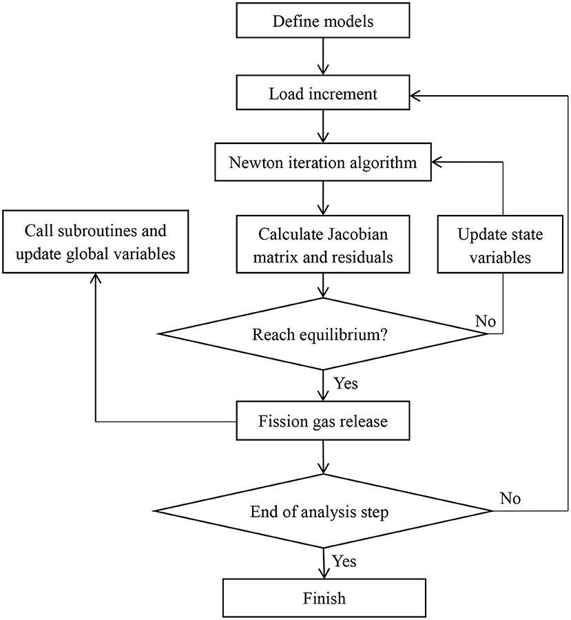
Figure 1. Flowchart of computation.
In this study, the sequential coupling technique is adopted to solve the coupled thermo-mechanical problem. The calculation results show that the efficiency and numerical stability of the sequential coupling algorithm are better than the fully coupled algorithm. The Newton algorithm is used for non-linear iteration, and the subroutines are called at each integration point in each iteration to obtain the physical parameters required to compute the elemental mass matrix, the stiffness matrix and the load vector. The flowchart of solving the above-mentioned equations by the non-linear finite element method is shown in Figure 1. It should be noticed that this paper uses an explicit method to calculate and update the fission gas release.
Thermo-Mechanical Model of ATF Materials
Thermal Models
Thermal Conductivity
Thermal conductivity is a determinant parameter of the thermo-mechanical properties of fuel materials. It affects both the thermal behavior and the mechanical behavior (such as thermal creep) of the fuel. High thermal conductivity can effectively reduce the temperature and its gradient of the fuel, which is generally beneficial to improve the performance of fuels.
In this study, the model of the thermal conductivity of U3Si2 from the Handbook (White, 2018) is adopted. The Hayes Model (Hayes et al., 1990a) is adopted for the model of thermal conductivity of UN. The thermal conductivity of FeCrAl is described in the report of Yamamoto et al. (2017). The thermal conductivity of SiC/SiC composite is described in the report of Koyanagi and Katoh (2018). Figure 2 shows that the thermal conductivity of fresh UN and U3Si2, which is remarkly higher than that of UO2. The high thermal conductivity is one of the most prominent features of ATFs.
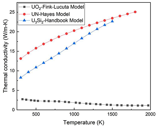
Figure 2. Thermal conductivities of fresh U3Si2 (White, 2018), UN (Hayes et al., 1990a), and UO2 (Williamson, 2011).
Specific Heat
In this work, the specific heat model of U3Si2 is also adopted from the Handbook (White, 2018) for consistency with the thermal conductivity model. For UN, the Hayes Model (Hayes et al., 1990b) is adopted. The fitting formula of the specific heat of FeCrAl consists of two segments. The first segment is applicable to the temperature above the Curie temperature but below the melting point, while the second segment is a third-order polynomial applicable to the temperature below the Curie temperature (Raju et al., 2009). With the temperature range from 200 to 2,400 K, the specific heat of SiC can be approximately expressed by a temperature-dependent function (Snead et al., 2007).
Mechanical Models
Creep Model
As fuel rods are exposed in an environment with high temperature, high pressure and high irradiation, the creep effect has a significant influence on the deformation of fuels. For U3Si2, Metzger (2016) proposes a creep model which accounts for athermal and thermal creep, i.e., when the temperature is below 0.45Tmelt(=872.0 K, where Tmelt is the melting point), athermal creep is activated. Above 872.0 K, creep is thermally activated. Thermal creep is driven by two different mechanisms that under low stress, i.e., σ/G ≤ 10−4, where σ is the stress and G is the shear modulus, the creep is governed by grain boundary diffusion (Coble creep). And under high stress, i.e., σ/G > 10−4, the creep is driven by dislocation slip and climb (dislocation creep).
For UN, the irradiation creep is dominant under PWR conditions. Therefore, it is acceptable to neglect thermal creep in the present study. The irradiation creep rate in s−1 for UN is given as (Feng et al., 2011):
where σ is the stress in MPa, p is the porosity, f is the fission density in fissions/cm3s.
Yamamoto et al. (2017) proposes a generalized thermal creep equation for all types of FeCrAl alloys:
where is the strain rate in s−1, σ is the stress in MPa and T is the temperature in K with 623 K ≤ T ≤ 1473 K, 1 MPa ≤ σ ≤ 150MPa.
The irradiation creep of FeCrAl is the same as that adopted by BISON (Hales et al., 2015),
where is the strain rate in s−1, σ is the effective stress in MPa and Φ is the neutron flux in n/m2s.
It is proposed by Koyanagi et al. (2017) that the thermal creep rates of SiC-based materials are very low at the temperature below ~1,000°C. Therefore, for normal operation temperatures, the thermal creep can be neglected for thermo-mechanical modeling of SiC cladding. Moreover, the irradiation creep of SiC can be neglected for modeling purpose as well (Koyanagi et al., 2016).
Swelling
Swelling is an important form of deformation of fuel materials. The swelling of pellets directly affects the gap width, thereby affecting the gap heat conduction and the PCMI.
An empirical burnup-dependent expression for the swelling of U3Si2 has been proposed by Metzger et al. (2014) by using the experimental data from Finlay et al. (2004). The total volumetric fuel swelling consists of the normal swelling part and the densification part. It is assumed that the densification behavior of U3Si2 is the same as that of UO2 which is modeled by the ESCORE empirical model (Gamble et al., 2019).
It is recommended by Feng et al. (2011) that the total swelling rate of UN is,
where Bu is burnup in FIMA. Irradiation-induced densification is neglected for UN fuel (Feng et al., 2011).
For cladding, the main contribution of the swelling is the irradiation-induced swelling. A simple linear model scaling with neutron flux is used to describe the FeCrAl swelling behavior according to the report by Sweet et al. (2018) and BISON's manual (Hales et al., 2015):
where is the strain rate in s−1 and Φ is the neutron flux in n/m2s.
The irradiation swelling of SiC is expressed by the model of Katoh et al. (2018):
where S is swelling strain, γ is displacement damage in dpa, γC and SS are functions of temperature:
where T is the temperature in K with a valid range from 473 to 1,073 K.
Fission Gas Release
The release of fission gas mainly includes two parts, i.e., the thermal release and the athermal release (Olander, 1976). Both the two release mechanisms are considered by adding the individual release fraction.
Forsberg-Massih model proposed by Forsberg and Massih (1985) is chosen as the thermal release model in this paper. Considering the predicted release ratio by the Forsberg-Massih model is conservative, this paper calibrates the dominant parameters according to the experimental measurement of UO2 fuel. For different fuel materials, the gas atomic diffusion coefficient within the grain may vary.
The diffusion coefficient of fission gas within U3Si2 grains was proposed by Barani et al. (2019)):
where k = 1.380649 × 10⁻²³ J/K is the Boltzmann constant, T(K) is the temperature.
The diffusion coefficient of fission gas within UN grain was proposed by Feng et al. (2011):
where D (cm2/s) is the diffusion coefficient of UN, is a factor related to the relative density ρ (%TD), FB = 30+Bu with Bu the burnup in MWd/kgU, f (fissons/cm3s) is the fission rate density, K (W/mK) is the thermal conductivity, T(K) is the temperature.
The athermal release of fission gas can be described by the COPERNIC FGR model (Bernard et al., 2002). Neglecting the recoil contribution, the athermal FGR fraction is of the form,
where F is the athermal FGR fraction, is a model parameter, S/V is the specific surface of the fuel grain (cm−1) and B is burnup (MWd/kgU).
Fuel Rod Model
The simplified fuel rod with three pellets is considered in the simulation. The axisymmetric geometric configuration is illustrated in Figure 3. The major operation parameters are listed in Table 1.
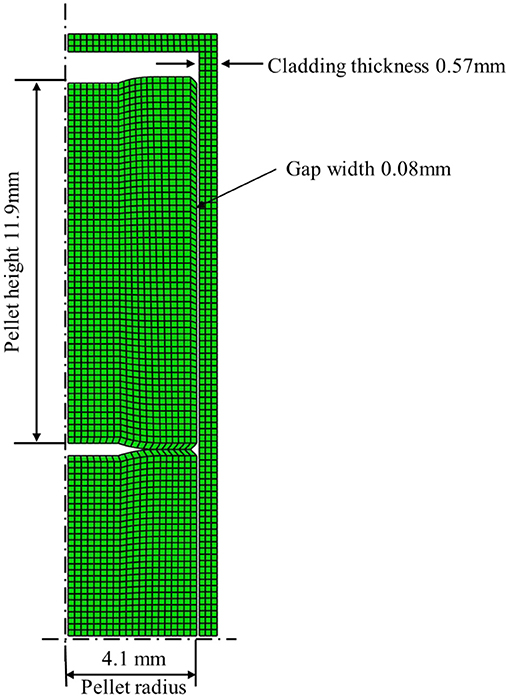
Figure 3. The geometry and the mesh of the fuel rod.
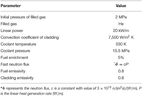
Table 1. Operation parameters.
The axisymmetric thermal-mechanical coupling element, i.e., CAX4T, is adopted. An element size of around 0.2 mm has been assigned for both the pellet and the cladding. Mesh-insensitivity has been ensured. The coupled temperature-displacement procedure is chosen to perform the analysis.
Results and Discussion
Model Validation
Considering experimental data of ATFs is rather limited, comparison with other literature work can provide a reference for the reliability of the present results. The predicted behavior of the U3Si2-FeCrAl combination is compared with that reported in He et al.'s work (2018). The geometry of the fuel and the boundary conditions (LHGR, coolant pressure, coolant temperature, etc.) are set the same as those in He's work, i.e., the pellet radius, the cladding thickness and the initial gap width are set as 4.3, 0.37, and 0.08 mm, respectively. The fuel centerline temperature, the evolution of the gap width, the gap heat transfer coefficient and the plenum pressure are compared in Figure 4. The maximum average burnup in He's work is around 40 MWd/kgU while it reaches 60 MWd/kgU in the present study.
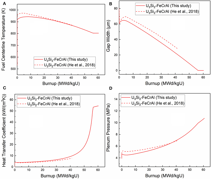
Figure 4. Comparison of (A) Fuel centerline temperature, (B) Gap width, (C) Gap heat transfer coefficient, (D) Plenum pressure.
As shown in Figure 4, fairly good agreement is obtained for fuel centerline temperature because similar thermal conductivity models of fuel and cladding are adopted by both work. The tendency of the evolution of gap width is similar because the same fuel densification model and fuel swelling model are adopted. The deviation of the gap width is mainly due to the different mechanical models of the cladding. In He's work, the thermal expansion of cladding adopts Shimizu's model (1965). While in our work, the thermal expansion of cladding is taken from Yamamoto's work (2017) and the value is much higher than that of Shimizu's model. The gap heat transfer coefficient is similar at the beginning due to the same gap heat transfer model are adopted. However, it is influenced by the gap width after 20 MWd/kgU burnup. As for plenum pressure, the growth of plenum pressure of the present work is more rapid than that in He's work due to an earlier gap closure and the fission gas release.
Influence of Pellet Materials
In order to compare the performance of the advanced fuels, the cladding material is fixed as FeCrAl and the behaviors of UO2, U3Si2, and UN are, respectively studied. The fuel centerline temperature, the gap width, the stress distribution as well as the pellet-cladding mechanical interaction (PCMI) are studied.
Figure 5 shows the evolution of the fuel centerline temperature of the three combinations. It is obvious that the centerline temperatures of the two ATFs is 400 ~600 K lower than that of UO2, due to their relatively high thermal conductivity. It is also noticed that for the U3Si2-FeCrAl combination, the temperature remains nearly constant after 55 MWd/kgU when the PCMI occurs. Owing to a much smaller gap size of U3Si2-FeCrAl shown in Figure 6, the heat conduction of the gap is significantly higher than that of UO2-FeCrAl. It can reduce the thermal resistance of the fuel rod thus resulting in a decrease of the fuel centerline temperature.
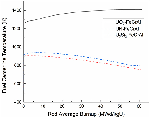
Figure 5. Comparison of fuel centerline temperature of UO2, UN, and U3Si2 with the FeCrAl cladding.
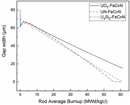
Figure 6. Evolution of gap width of UO2-FeCrAl, UN-FeCrAl, and U3Si2-FeCrAl with burnups.
Figure 6 illustrates the variation of gap width with the average burnup. In the beginning, thermal expansion is dominant and as a consequence, U3Si2-FeCrAl has the smallest initial gap width which can be attributed to the highest thermal expansion coefficient of U3Si2. As the densification of UN is not considered, an increase of the gap width does not appear. It was also found that the gap becomes small gradually with burnup due to the fuel swelling. U3Si2 has the highest swelling rate, which results in the earliest gap closure.
The distribution of the temperature and the maximum principal stress at the initial burnup is shown in Figures 7, 8 respectively. It is noticed that the maximum principal stress of UO2 is nearly 650 MPa due to its higher temperature gradient. It will cause the fuel cracking in the radial direction considering the tensile strength of UO2 is only 110 MPa. It can be seen that U3Si2 and UN have a much flatter distribution of temperature, which results in a much lower temperature gradient. Thus, the maximum principal stress for both U3Si2 and UN is < 200 MPa which greatly reduces the fuel fragmentation and relocation.
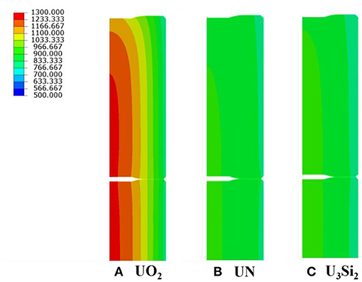
Figure 7. Fuel temperature (K) of (A) UO2 (B) UN, and (C) U3Si2 at BOC with FeCrAl cladding.
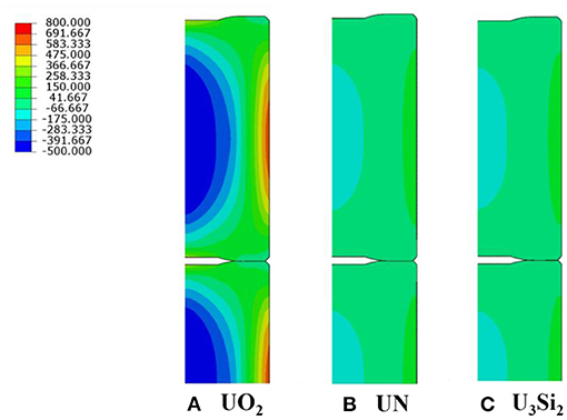
Figure 8. Maximum principal stress (MPa) of (A) UO2 (B) UN and (C) U3Si2 at BOC with FeCrAl cladding.
Influence of Cladding Materials
In order to compare the effects of cladding materials, the fuel material is fixed as U3Si2 and three types of cladding materials, i.e., FeCrAl, SiC, and Zr, are respectively investigated. The evolution of the fuel centerline temperature of the fuels with different claddings is shown in Figure 9. For all the claddings, there is a continuous temperature decrease until the closure of the pellet-cladding gap. During the whole evolution, the fuel centerline temperature of U3Si2-SiC is evidently higher than that of U3Si2-FeCrAl and U3Si2-Zr. This is because the thermal conductivity of the irradiated SiC (about 3.6 W/m.K) (Koyanagi and Katoh, 2018) is notably lower than that of FeCrAl and Zr (both range from around 12–22 W/m·K when temperature varies from 400–1,000 K) (Yamamoto et al., 2017).
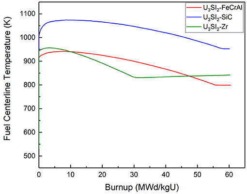
Figure 9. Fuel centerline temperature of three types of cladding with U3Si2.
It is also noticed that there is no apparent difference between the maximum fuel centerline temperatures of U3Si2-FeCrAl and U3Si2-Zr due to the similar thermal conductivity of FeCrAl and Zr. The fuel centerline temperature of U3Si2-Zr decreases more rapidly than that of U3Si2-FeCrAl due to the higher pellet-cladding gap heat transfer which is mainly caused by their different gap widths. Moreover, due to a later gap closure of U3Si2-FeCrAl, the fuel centerline temperature of U3Si2-FeCrAl finally reaches a lower level.
The evolution of the pellet-cladding gap width is shown in Figure 10. The U3Si2-Zr combination is found to have the earliest gap closure, indicating an earliest pellet-cladding mechanical interaction. This also signifies that the adoption of ATF claddings can effectively delay the gap closure as well as the PCMI.
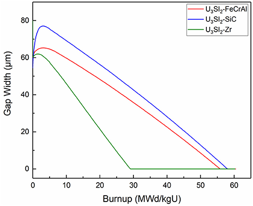
Figure 10. Influence of cladding material on evolution of gap width (fuel: U3Si2).
In order to find out the influences of different claddings on the gap width, the radial displacement at the inner surface of cladding is presented in Figure 11. Under the pressure of coolant, the Zircaloy cladding has a displacement toward pellets due to the creep effect. After the PCMI occurs, its displacement has an outward increase driven by the fuel deformation. For FeCrAl and SiC claddings, the pressure of coolant has a negligent effect on the radial displacement due to the lower creep rate. For the radial displacement of SiC cladding, there is an apparent increase at first due to its much higher irradiation swelling until the swelling is saturated.
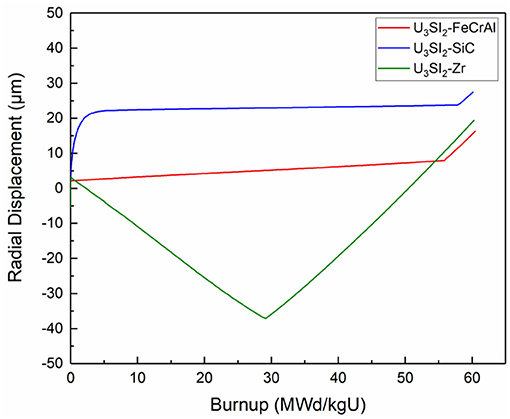
Figure 11. Radial displacement at inner cladding surface of three types of cladding.
Figure 12 presents the evolutions of hoop stress of ATF claddings compared with that of Zircaloy cladding. The stresses are extracted from the outer radius of cladding at the mid-plane of the fuel rod. The hoop stress is negative (compressive) due to the pressure of coolant before the gap closure, and shows a sudden increase when the fuel and the cladding contacts. It is evident that the stress in both FeCrAl and SiC cladding is higher than that in Zircaloy cladding after the contact. This is expected because of the higher stiffness as well as the lower creep of both FeCrAl and SiC.
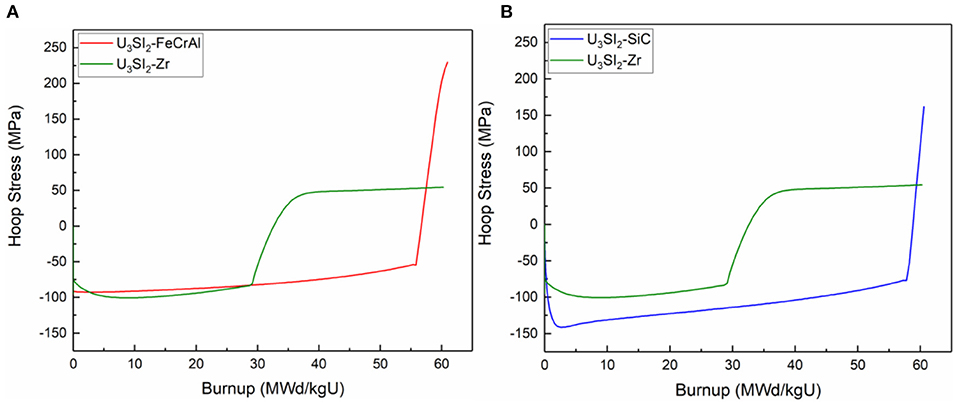
Figure 12. Comparison of cladding hoop stress evolution of U3Si2-FeCrAl and U3Si2-Zr (A) and of U3Si2-SiC and U3Si2-Zr (B).
Gas Release Behavior
Model Validation
In this paper, the fission gas release of different ATF fuels is simulated by choosing appropriate fission gas atomic diffusion coefficient. Considering the insufficient experimental data, this paper only compares the results by other software for the UN-SiC fuel combination. For convenience of comparison, the parameters used in the study are consistent with those in the literature (Rice, 2015).
In this paper, the simulation results of UN-SiC fission gas release behavior and the comparison with the simulation results of other programs are shown in Figure 13. It can be found that the results of this paper are similar to the results of BISON program and FRAPCON program. The simulated thermal release in this program starts at the burnup of 32MWd/KgU and reaches a total release ratio of about 3.3% at 60MWd/KgU.
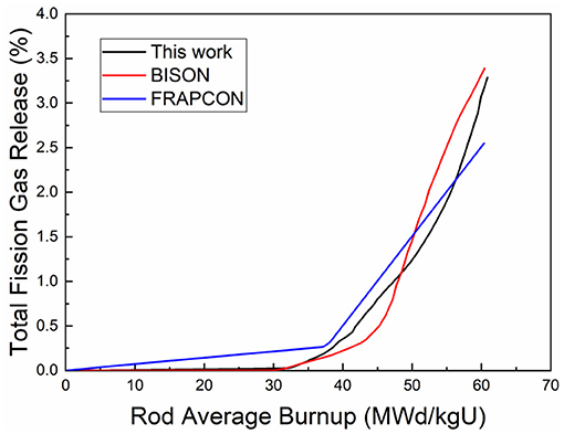
Figure 13. Fission gas release for UN/SiC at 20 kW/m.
Comparison of Fission Gas Release Behavior of Different Fuels
In order to study the fission gas release behavior of different fuels, FeCrAl is chosen as the cladding material. The predicted fission gas release of U3Si2, UN, and UO2 are shown in Figure 14.
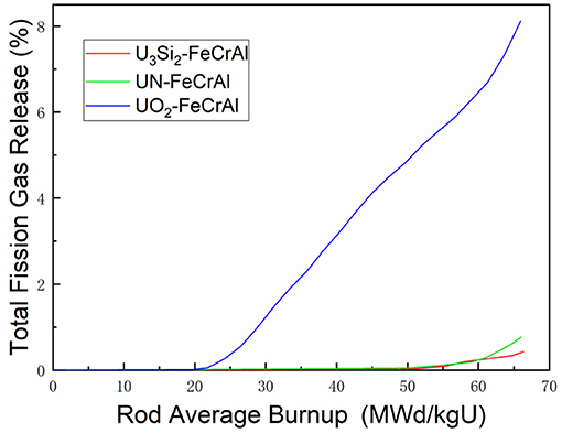
Figure 14. Fission gas release for different materials at 20 kW/m.
In this case, UO2 begins the thermal release at about 20MWd/KgU, much earlier than the 60MWd/KgU of UN. The fission gas release of U3Si2 is dominated by athermal release at burnup to 66MWd/KgU. The final fission gas release ratio of UO2 reaches about 8%, which is much higher than that of UN and U3Si2. As can be seen from Figure 5, the temperature of UO2 fuel is about 500 K higher than that of the other two fuels. This is the main reason that leads to the difference of fission gas thermal release and finally causes the great difference in total release ratio.
Summary
The thermal-mechanical models of typical ATFs, including U3Si2, UN for fuel materials, FeCrAl and SiC for cladding materials are summarized. Furthermore, the fission gas release models have been investigated and analyzed. Using non-linear finite element simulation, the thermal-mechanical behaviors of UO2-FeCrAl, UN-FeCrAl, U3Si2-FeCrAl, U3Si2-Zr, and U3Si2-SiC combinations have been studied.
The conclusions are summarized as follows,
1. Compared with UO2, the ATFs have a lower fuel centerline temperature and flatter radial temperature profile owing to the higher thermal conductivities of ATFs. A lower temperature gradient contributes to a flatter stress distribution and thus reducing the severity of fuel fragmentation. Even though the high swelling rate of U3Si2 and UN causes an earlier PCMI, the gap closure can further reduce the fuel centerline temperature.
2. Compared with the Zircaloy cladding, the SiC cladding causes higher fuel centerline temperature due to the degradation of SiC thermal conductivity under irradiation. Adoption of FeCrAl cladding causes lower fuel centerline temperature at high burnup when compared with the case of Zircaloy cladding. It is noticed that the adoption of ATF claddings can effectively delay the gap closure as well as the PCMI. A significant rise of hoop stress is found in both FeCrAl and SiC claddings after PCMI due to their higher stiffness and lower creep rate.
3. Under the same conditions, the fission gas release rates of UN and U3Si2 are lower than UO2.
Data Availability Statement
The raw data supporting the conclusions of this article will be made available by the authors, without undue reservation.
Author Contributions
ZZ: study of cladding material. PY: study of fuel materials. CX: study of gas release behavior. ZC: code development. YCh: manuscript proof. GS: manuscripy proof. ZY: manuscript proof. ZJ: FeCrAl models. HX: SiC models. YCe: neutronics study. All authors contributed to the article and approved the submitted version.
Funding
We thank the funding support from National key research and development program (No. 2018YFB1900400) and support from Nuclear Power Institute of China (Contract No. HT-ATF-14-2018001).
Conflict of Interest
The authors declare that the research was conducted in the absence of any commercial or financial relationships that could be construed as a potential conflict of interest.
References
Barani, T., Pastore, G., Pizzocri, D., Andersson, D. A., Matthews, C., Alfonsi, A., et al. (2019). Multiscale modeling of fission gas behavior in U3Si2 under LWR conditions. J. Nucl. Mater. 522, 97–110. doi: 10.1016/j.jnucmat.2019.04.037
Bernard, L. C., Jacoud, J. L., and Vesco, P. (2002). An efficient model for the analysis of fission gas release. J. Nucl. Mater. 302, 125–134. doi: 10.1016/S0022-3115(02)00793-6
Feng, B., Karahan, A., and Kazimi, M. S. (2011). “Steady-state nitride fuel behavior modeling with FRAPCON EP and its application to PWRs,” in Proceedings of ICAPP (Charlotte, NC).
Finlay, M. R., Hofman, G. L., and Snelgrove, J. L. (2004). Irradiation behaviour of uranium silicide compounds. J. Nucl. Mater. 325, 118–128. doi: 10.1016/j.jnucmat.2003.11.009
Forsberg, K., and Massih, A. R. (1985). Diffusion theory of fission gas migration in irradiated nuclear fuel UO2. J. Nucl. Mater. 135, 140–148. doi: 10.1016/0022-3115(85)90071-6
Gamble, K. A., Pastore, G., Andersson, D., and Cooper, M. W. (2019). ATF Material Model Development and Validation for Priority Fuel Concept. Idaho Falls, ID: Idaho National Lab. (INL). doi: 10.2172/1547325
Hales, J. D., Williamson, R. L., Novascone, S. R., Pastore, G., Spencer, B. W., Stafford, D. S., et al. (2015). BISON Theory Manual: The Equations behind Nuclear Fuel Analysis, BISON Release 1.2. Idaho Falls, ID: Idaho National Laboratory, INL/EXT-13-29930 Rev. 2.
Hayes, S. L., Thomas, J. K., and Peddicord, K. L. (1990a). Material property correlations for uranium mononitride: III. Transport properties. J. Nucl. Mater. 171, 289–299. doi: 10.1016/0022-3115(90)90376-X
Hayes, S. L., Thomas, J. K., and Peddicord, K. L. (1990b). Material property correlations for uranium mononitride: IV. Thermodynamic properties. J. Nucl. Mater. 171, 300–318. doi: 10.1016/0022-3115(90)90377-Y
He, Y., Chen, P., Wu, Y., Su, G. H., Tian, W., and Qiu, S. (2018). Preliminary evaluation of U3Si2-FeCrAl fuel performance in light water reactors through a multi-physics coupled way. Nucl. Eng. Des. 328, 27–35. doi: 10.1016/j.nucengdes.2017.12.019
Katoh, Y., Koyanagi, T., McDuffee, J. L., Snead, L. L., and Yueh, K. (2018). Dimensional stability and anisotropy of SiC and SiC-based composites in transition swelling regime. J. Nucl. Mater. 499, 471–479. doi: 10.1016/j.jnucmat.2017.12.009
Koyanagi, T., and Katoh, Y. (2018). Radial Thermal Conductivity Measurement for SiC Composite Tubes. Oak Ridge, TN: Oak Ridge National Lab (ORNL). doi: 10.2172/1479730
Koyanagi, T., Katoh, Y., Ozawa, K., Shimoda, K., Hinoki, T., and Snead, L. L. (2016). Neutron-irradiation creep of silicon carbide materials beyond the initial transient. J. Nucl. Mater. 478, 97–111. doi: 10.1016/j.jnucmat.2016.06.006
Koyanagi, T., Katoh, Y., Singh, G., and Snead, M. (2017). SiC/SiC Cladding Materials Properties Handbook. Nuclear Technology Research and Development, ORNL/TM-2017/M-2385.
Li, W., and Shirvan, K. (2019). U3Si2-SiC fuel performance analysis in BISON during normal operation. Ann. Nucl. Energy 132, 34–45. doi: 10.1016/j.anucene.2019.04.021
Liu, R., Zhou, W., and Cai, J. (2018). Multiphysics modeling of accident tolerant fuel-cladding U3Si2-FeCrAl performance in a light water reactor. Nucl. Eng. Des. 330, 106–116. doi: 10.1016/j.nucengdes.2018.01.041
Metzger, K. E. (2016). Analysis of pellet cladding interaction and creep of U3Si2 fuel for use in light water reactors (Doctoral dissertation). University of South Carolina, Columbia, SC, United States.
Metzger, K. E., Knight, T. W., and Williamson, R. L. (2014). Model of U3Si2 Fuel System Using BISON Fuel Code. Idaho Falls, ID: Idaho National Laboratory (INL).
Olander, D. R. (1976). Fundamental Aspects of Nuclear Reactor Fuel Elements: Solutions to Problems. Department of Nuclear Engineering, California University, Berkeley, United States. doi: 10.2172/7290222
Qiu, B. W., Wang, J., Deng, Y. B., Wang, M. J., Wu, Y. W., and Qiu, S. Z. (2020). A review on thermohydraulic and mechanical-physical properties of SiC, FeCrAl and Ti3SiC2 for ATF cladding. Nucl. Eng. Technol. 52, 1–13. doi: 10.1016/j.net.2019.07.030
Raju, S., Ganesh, B. J., Rai, A. K., Mythili, R., Saroja, S., Mohandas, E., et al. (2009). Measurement of transformation temperatures and specific heat capacity of tungsten added reduced activation ferritic–martensitic steel. J. Nucl. Mater. 389, 385–393. doi: 10.1016/j.jnucmat.2009.02.030
Rice, A. (2015). Intercode advanced fuels and cladding comparison using bison, frapcon, and femaxi fuel performance codes.
Snead, L. L., Nozawa, T., Katoh, Y., Byun, T. S., Kondo, S., and Petti, D. A. (2007). Handbook of SiC properties for fuel performance modeling. J. Nucl. Mater. 371, 329–377. doi: 10.1016/j.jnucmat.2007.05.016
Sweet, R. T. (2018). Thermo-mechanical analysis of iron-chromium-aluminum (FeCrAl) alloy cladding for light water reactor fuel elements (Doctor of Philosophy). University of Tennessee, Knoxville, TN, United States.
Sweet, R. T., George, N. M., Maldonado, G. I., Terrani, K. A., and Wirth, B. D. (2018). Fuel performance simulation of iron-chrome-aluminum (FeCrAl) cladding during steady-state LWR operation. Nucl. Eng. Des. 328, 10–26. doi: 10.1016/j.nucengdes.2017.11.043
Williamson, R. L. (2011). Enhancing the ABAQUS thermomechanics code to simulate multipellet steady and transient LWR fuel rod behavior. J. Nucl. Mater. 415, 74–83. doi: 10.1016/j.jnucmat.2011.05.044
Keywords: accident-tolerant fuel, multiphysics coupling, finite element method, fisson gas release, creep, swelling
Citation: Zeng Z, Pan Y, Chen X, Zhang C, Yin C, Gao S, Zhou Y, Zhang J, He X and Yuan C (2021) Three-Dimensional Modeling of Thermal-Mechanical Behavior of Accident Tolerant Fuels. Front. Energy Res. 9:636502. doi: 10.3389/fenrg.2021.636502
Received: 01 December 2020; Accepted: 23 February 2021;
Published: 17 March 2021.
Edited by:
Shoaib Usman, Missouri University of Science and Technology, United StatesReviewed by:
Mingjun Wang, Xi'an Jiaotong University, ChinaWenxi Tian, Xi'an Jiaotong University, China
Copyright © 2021 Zeng, Pan, Chen, Zhang, Yin, Gao, Zhou, Zhang, He and Yuan. This is an open-access article distributed under the terms of the Creative Commons Attribution License (CC BY). The use, distribution or reproduction in other forums is permitted, provided the original author(s) and the copyright owner(s) are credited and that the original publication in this journal is cited, in accordance with accepted academic practice. No use, distribution or reproduction is permitted which does not comply with these terms.
*Correspondence: Zhang Chunyu, emhhbmdjaHk1QG1haWwuc3lzdS5lZHUuY24=