 Xianfeng Ma
 Wenjie Zhang
 Jishen Jiang
- Sino-French Institute of Nuclear Engineering and Technology, Sun Yat-sen University, Zhuhai, China
In situ tensile tests and crystal plasticity finite element modeling (CPFEM) were used to study the deformation and cracking behaviors of Cr-coated Zr-4 alloys for accident tolerant fuel claddings under tension. Based on the experimental results, vertical cracks in the coating generally initiated from the interface between the coating and the substrate, and expanded to the top surface of the coating. In addition, under large deformation, the vertical cracks also resulted in interfacial cracks that initiated from the cracking tips and propagated along the interface. According to the CPFEM, the cracking behaviors were mainly caused by the substantial stress concentration at the coating/substrate interface and at the grain boundaries in the Cr coating. The preferential crack initiation was related to the strain localization associated with grain orientation variation and strain mismatch.
Introduction
After the Fukushima Daiichi accident in 2011, the concept of accident tolerant fuel (ATF) was proposed to enhance the tolerance of light water reactors under both design-basis (DB) and beyond-design-basis (BDB) accident conditions (Zinkle et al., 2014; Tang et al., 2017; Terrani, 2018). Developing high-oxidation-resistant surface coatings is one of the most effective prospective method to improve the accident tolerance of Zr claddings during loss-of-coolant accident (LOCA) or station blackout (SBO) conditions (Zinkle et al., 2014; Tang et al., 2017). The material selection, preparation technologies, and oxidation resistance of ATF coatings have been further studied in recent years. Recently, several types of coatings, such as Cr, CrN, and FeCrAl coatings, have been selected as promising candidates for ATF coatings (Terrani et al., 2013; Maier et al., 2015; Tallman et al., 2015; Usui et al., 2015; Tang et al., 2017; Wang et al., 2018; Zhong et al., 2018; Meng et al., 2019). However, information on the mechanical performance, particularly the deformation and cracking behavior, of the ATF coatings is quite limited (Jiang et al., 2018; Ma et al., 2021). The strength assessment and failure mechanisms of the ATF coating systems under either normal or LOCA conditions is an essential performance index that must be investigated before their application.
The ATF coatings developed in previous studies include ceramic materials [e.g., SiC (Usui et al., 2015) and CrN (Meng et al., 2019)], MAX-phase materials [e.g., Ti3SiC2 (Tallman et al., 2015) and Ti2AlC (Maier et al., 2015)], metallic materials [e.g., Cr (Zhong et al., 2018; He et al., 2019; Ma et al., 2021) and FeCrAl (Terrani et al., 2013)], and multi-layered composite coatings [e.g., ZrO2/FeCrAl (Wang et al., 2018)]. Among them, metallic Cr coatings have become the most popular and are the most likely to be applied in the near future. The conventional oxidation resistance and mechanical properties of Cr coatings have been systematically investigated in previous studies. For example, He et al. (2019) found that the oxide layer that formed on the Cr coating prepared by the multi-arc ion plating technique caused a 93.35% reduction in the oxidation weight gain of a Zr-4 alloy during oxidation at 1,060°C, which reflected the remarkable oxidation resistance of the Cr coating. Brachet et al. (2019), Brachet et al. (2020) prepared Cr coatings using a physical vapor deposition (PVD) process and found that they exhibited superior oxidation and fretting resistance as well as good adhesion to the Zr substrate. Kim et al. (2015) found that a thick Cr coating (90 μm in thickness) slightly increased the tensile and compressive strengths of the coated Zr-4 substrate, which might be due to its high strength and ductility. However, Brachet et al. (2019) found that a thin Cr coating (10 μm in thickness) had a negligible effect on the tensile strength of the coated substrate at room temperature, although it did have a positive effect at high temperatures.
The mechanical properties of Cr-coated Zr alloys are highly related to the deformation and cracking behavior of the Cr coating. As illustrated in Figure 1 (Jiang et al., 2017), under uniaxial tensile loading, surface cracks penetrate through the coating thickness to form parallel channel cracks (Figure 1A). When the interfacial adhesion between the coating and the substrate is weak, vertical cracks may change direction and propagate along the interface to form interfacial cracks (Figure 1B). However, when the interfacial adhesion is sufficiently strong, interfacial cracks are difficult to initiate, and vertical cracks may penetrate the substrate under continuous loading (Figure 1C). In some cases with moderate interfacial adhesion, both vertical cracks and interfacial cracks may occur simultaneously under severe deformation (Figure 1D). The cracking behavior directly reflects the coating strength and interfacial adhesion. In our previous work (Jiang et al., 2020), the cracking behavior of a Cr-coated Zr-4 substrate was preliminarily studied. The surface crack evolution was captured by in situ observations, and the crack density was predicted by a modified shear-lag model. Some key mechanical properties of the Cr coating, such as the tensile strength and interfacial fracture toughness, were evaluated by in situ tensile tests and macroscopic finite element models (FEMs). However, both the Cr coating and Zr substrate possess crystal structures, and their grain size and orientation have a remarkable influence on the cracking mode. Thus, a mesoscopic FEM based on the crystal plasticity theory must be developed to further study the deformation and cracking behavior of the Cr coating system. This study used a method that combined in situ tensile tests and a crystal plasticity finite element model (CPFEM) to investigate the elastoplastic deformation and cracking behavior of the Cr- coated Zr- 4 substrate system under tension, and the mechanism of crack initiation and propagation of the Cr coating was analyzed.
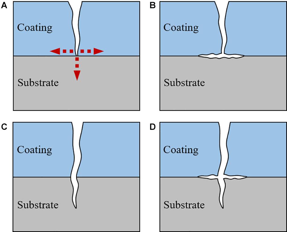
Figure 1. Typical cracking modes of coatings under tensile loading: (A) vertical crack penetrates through the coating, (B) vertical crack propagates at the interface, (C) vertical crack penetrates to the substrate and (D) vertical crack propagates at the interface and penetrates to the substrate simultaneously.
Materials and Experiments
Experimental Materials
Zr-4 alloy was selected as the substrate material, and its chemical composition is provided in Table 1. The original Zr-4 alloy bar was subjected to an annealing treatment at 800°C for 24 h in vacuum, after which it was cut into dog-bone-shaped tensile samples with a gauge length of 20 mm. The typical microstructure of the resulting Zr-4 alloy is shown in Figure 2A, with a grain size of approximately 20 μm. A multi-arc ion plating technique was used to deposit the Cr coating (purity of approximately 99.9%) on the surface of the Zr-4 alloy. Detailed deposition parameters are listed in Jiang et al. (2020). The surface and cross-sectional morphologies of the Cr-coated Zr-4 substrate are shown in Figures 2B,C. The coating had a dense microstructure with small grains that were 1 μm in size. The coating thickness was relatively uniform with an average thickness of 10 μm. The Cr coating bonded tightly to the substrate, and no micro-cracks or micro-voids were found at either the surface or the interface.

Table 1. Chemical composition of the Zr-4 alloy (wt.%).
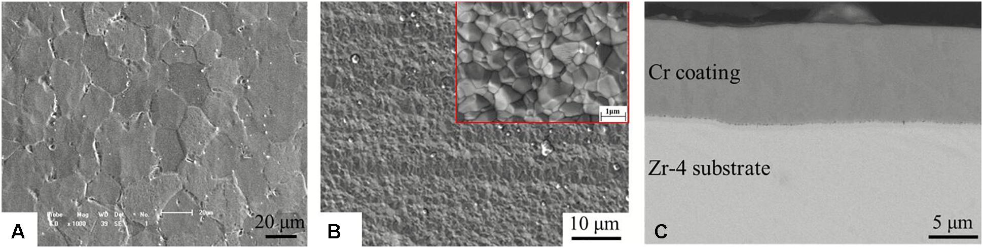
Figure 2. Surface morphologies of (A) the uncoated Zr-4 alloy and (B) the Cr coating, and (C) the interfacial morphology of the as-deposited Cr-coated Zr-4 substrate.
In situ Tensile Test Method
As shown in Figure 3, in situ tensile tests of the Cr-coated samples were performed using a mechanical experimental device equipped with a high-magnification optical microscope, a mechanical loading system (for tensile tests, fatigue tests, and three-point bending tests), and a data acquisition system. As shown in Figure 3B, the test sample was fixed to the mechanical loading system by two clamps. The optical microscope (3,000 × maximum) was suspended over the mechanical loading system to observe the deformation and cracking behavior on the surface of the sample during the tensile process. Tensile tests were performed under the displacement control mode at a constant rate of 5 × 10⁻³ mm/s, i.e., a strain rate of 2.5 × 10⁻⁴ s–1. The tensile test was paused at various moments to capture the crack initiation and its evolution on the coating surface. Note that an area of 1,450 μm × 1,100 μm where the first visible surface crack initiated was imaged to capture the crack evolution. The engineering strain was calculated by dividing the tensile displacement by the original gauge length. The tensile test ended when the sample fractured entirely. After the tensile test, the cross section of the sample was examined using scanning electron microscopy (SEM) to analyze the interfacial cracking behavior.
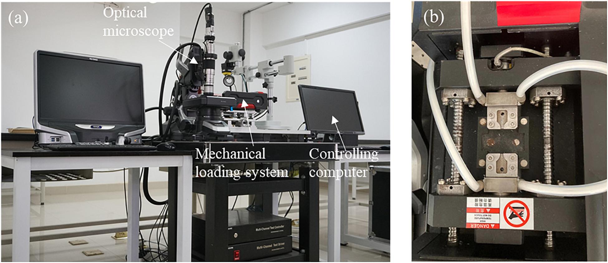
Figure 3. (A) In situ mechanical device equipped with a high-magnification optical microscope and (B) view of the mechanical loading system.
Crystal Plasticity Theory and Finite Element Simulation Procedure
Crystal Plasticity Theory
A rate-dependent crystal plasticity theory based on the classical work of Taylor and Hill (Taylor, 1938; Lee, 1969; Hill and Rice, 1972) is applied to describe the anisotropic constitutive relation of the materials. The model is capable of modeling the plasticity deformation of crystals considering the crystal orientation effects. In this work, the flow rule on each slip system is assumed to follow a power–law relationship (Hutchinson, 1976),
where is the shear rate, τα is the resolved shear stress, and m are the reference strain rate and rate sensitivity coefficient of slip system α, respectively, gα is the critical resolved shear stress determined by the hardening state of the material on the crystal scale.
In this study, a Voce hardening model (Agnew et al., 2001) was chosen to model the hardening of the Zr-4 alloy substrate, which has been widely used for hexagonal close-packed (HCP) crystal structure. An exponential hardening model (Peirce et al., 1982) was chosen to model the hardening of the Cr coating, which has a body-centered cubic (BCC) crystal structure. The hardening laws are expressed as follows:
(i) Voce hardening model:
where is the critical shear stress of the α-th slip system in the initial state. is the critical shear stress of the α-th slip system at steady state. γ is the sum of the shear strains of all the slip systems in the current step. and are the initial and final hardening rates, respectively.
The increment of the critical shear stress of the α-th slip system in this increment step can be solved by the following formula:
where qαβ represents material self-hardening (α = β) and latent hardening (α ≠ β). Its value is assigned as 1.0 for coplanar slip systems and 1.4 otherwise.
(ii) Exponential hardening model:
The micromechanical interaction between any slip system β and the fixed slip system α is taken into consideration by
where hαβ represents the hardening matrix and is given as
where , a, g0, and g1 are the slip hardening parameters. In the simulation of Zr-4 deformation, twinning is regarded as a special slip system. Due to the polarity of the twinning, the lattice rotation caused by twinning is different from the lattice rotation caused by slip. In this study, the models proposed by Tomé et al. (1991) and Paul (1978) were used.
Finite Element Modeling
Calibration of Crystal Plasticity Material Parameters
The crystal plasticity material parameters of both the Zr-4 alloy and Cr coating were confirmed and calibrated first. Note that because no experimental data for Cr coatings deposited by the multi-arc ion plating method was available, the parameters of the Cr coating were assumed to be the same as those of pure Cr. The crystal plasticity model parameters of the Zr-4 alloy and pure Cr were chosen following Paul (1978), Holzwarth and Stamm (2002), Xu et al. (2009), and Yang et al. (2018). Regarding the hardening of Cr coating, the model parameters were chosen based on Raabe et al. (2005). The crystal plasticity parameters were calibrated using a trial-and-error method until the simulated tensile curves were consistent with those in the literature. Figure 4 displays the simulation results of the Zr-4 alloy and pure Cr, respectively, which show good agreement with the published results. Based on the calibration, the elastic modulus constants of Zr were confirmed to be C11 = 143.5 GPa, C12 = 72.5 GPa, C13 = 65.4 GPa, C33 = 164.9 GPa, C55 = 32.1 GPa, and C44 = 35.5 GPa, and the hardening parameters are listed in Table 2. The elastic matrix constants of pure Cr were confirmed to be C11 = 307.0 GPa, C12 = 70.3 GPa, and C44 = 80.9 GPa, and the hardening parameters are listed in Table 3.
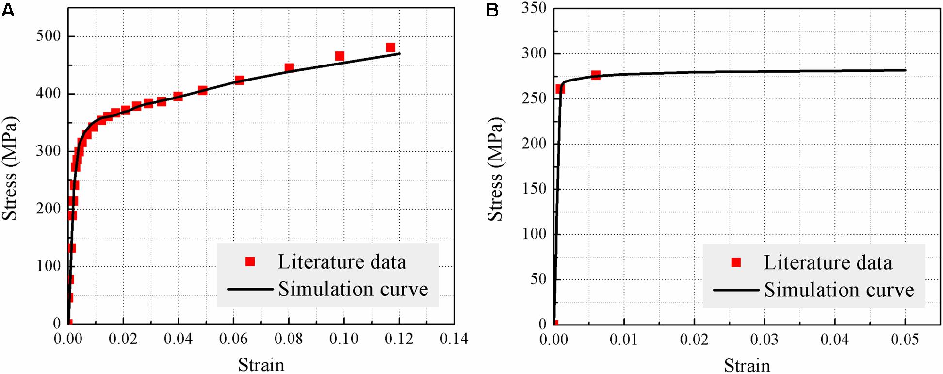
Figure 4. Comparison of the stress–strain curves of (A) the Zr alloy and (B) pure Cr calculated by crystal plasticity simulations with the experimental results (Paul, 1978; Holzwarth and Stamm, 2002; Raabe et al., 2005; Xu et al., 2009; Yang et al., 2018).

Table 2. Material parameters of the Zr alloy for crystal plasticity modeling.
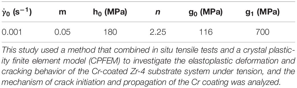
Table 3. Material parameters of pure Cr for crystal plasticity modeling.
Finite Element Model Set-Up
A two-dimensional FEM consisting of a 10 μm thick Cr coating and a 28.8 μm thick Zr-4 substrate was built in ABAQUS. The geometry, meshes, and boundary conditions of the model are shown in Figure 5. The interface between the Cr coating and the substrate was assumed to be flat, and no initial interfacial cracks or vertical surface cracks were included in the model. According to the author’s previous studies (see Wei et al., 2019; Brachet et al., 2020; Jiang et al., 2020), Cr coatings deposited by multi-arc ion plating possess columnar grain structures with an average width of 1 μm and thickness of 10 μm, whereas the Zr-4 substrate possesses equiaxed grains with an average size of 20 μm. For the convenience of finite element modeling, the grains of the Cr coating were assumed to be rectangular in the FEM, and the grains of the Zr-4 substrate were assumed to be pentagonal, as shown in Figure 5A. To study the effect of grain shape, a FE model with cubic grains was built for comparison. The obtained stress-strain curve was consistent with that of the model with pentagonal grains, indicating that the grain shape has negligible effect on the stress-strain curve. Considering the periodicity and symmetry, a two-period region containing 40 grains in the Cr coating and four grains in the Zr-4 substrate was chosen for the following simulation. As shown in Figure 5C, for symmetric boundary conditions, the left edge was constrained to move in the x direction, and the bottom edge was constrained to move in the y direction. For the periodic boundary condition, all nodes on the right edge were restricted by a multipoint constraint (MPC) method such that they were allowed to move in the x direction but remained in-plane and vertical. In addition, a uniform tensile strain was applied on the right edge, which was consistent with the tensile loading during the tensile test. Four-node plane-strain elements were generated in both the Cr coating layer and the Zr substrate layer for finite element meshing. As shown in Figure 5B, the entire model contained 2,468 elements, including 840 elements in the Cr coating. In the FEM, both the Cr coating and Zr-4 substrate were considered to be elastoplastic materials. A verified crystal plasticity model described in section “Crystal Plasticity Theory” has been implemented in ABAQUS using in-house user material subroutine (VUMAT) codes developed by the authors, to describe the stress–strain behaviors of polycrystalline alloys.
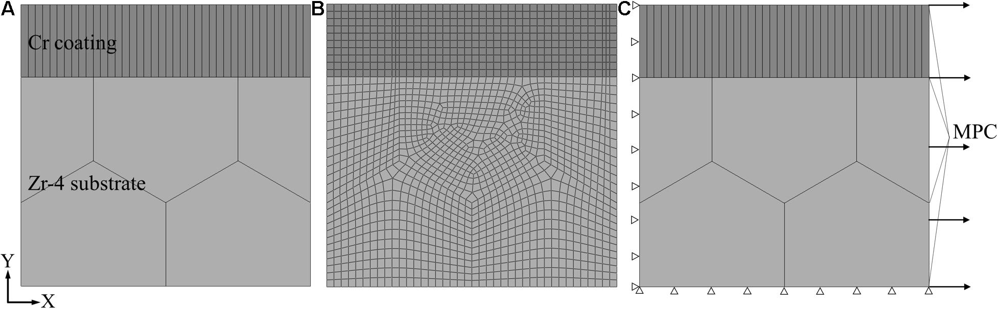
Figure 5. FEM of the coating–substrate system: (A) geometric model, (B) meshed model, and (C) boundary conditions.
Crack Analysis Based on the Cohesion Zone Model
In the FEM, the surface cracking behavior of the Cr coating under tension was also simulated based on the cohesion zone model (CZM). The FEM assumed that vertical cracks would initiate and propagate between two columnar grains in the Cr coating. Based on the in situ observation, surface cracks occurred when the strain reached 0.4%, while few interfacial cracks were found initiated from the surface crack tips when the strain was larger than 5% (Jiang et al., 2020), which reflected high interfacial adhesion property between the coating and the substrate. Therefore, in this FE model, the coating was assumed to bond tightly on the substrate and no interfacial cracks occurred in a small tensile strain range. As shown in Figure 6A, to model a vertical crack, a layer of cohesive elements with zero thickness was located in the middle of the Cr coating vertical to the interface. The CZM assumes that there is a cohesive zone ahead of a crack tip, where the separation of the material is restricted by cohesive tractions. The material behavior of the cohesive elements is characterized by a bilinear transition–separation law (TSL). Schematics of pure Mode I and Mode II TSLs are shown in Figures 6B,C, respectively. The TSL assumes that the elements have linear elastic behavior before damage; once a damage criterion is reached, damage initiates and accumulates continuously under external loading. Once the damage value reaches one, cracks will be initiated, and the related elements will be deleted to represent a crack surface. A detailed description of the CZM and TSL can be found in our previous work (Jiang et al., 2018). For the modeling of crack based on the CZM, the fracture strength (σ0) and critical energy release rate (i.e., fracture toughness, Gc) must be evaluated. Figure 7 displays the effects of σ0 and Gc on the strain for surface crack initiation, εc. It was shown that larger σ0 and (or) Gc led to larger εc (namely, later crack initiation). Besides, for a given σ0, the εc increased slowly with the increase of Gc. Based on the above computational results, to match with the experimental results that cracks occur at εc = 0.4%, σ0 and Gc were chosen as 180 MPa and 0.1 mJ/mm2, respectively.
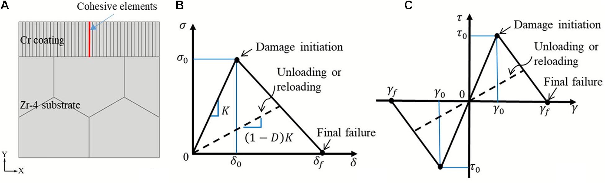
Figure 6. (A) Location of cohesive elements in the coating–substrate model, and the schematics of bilinear TSLs: (B) Mode I TSL and (C) Mode II TSL.
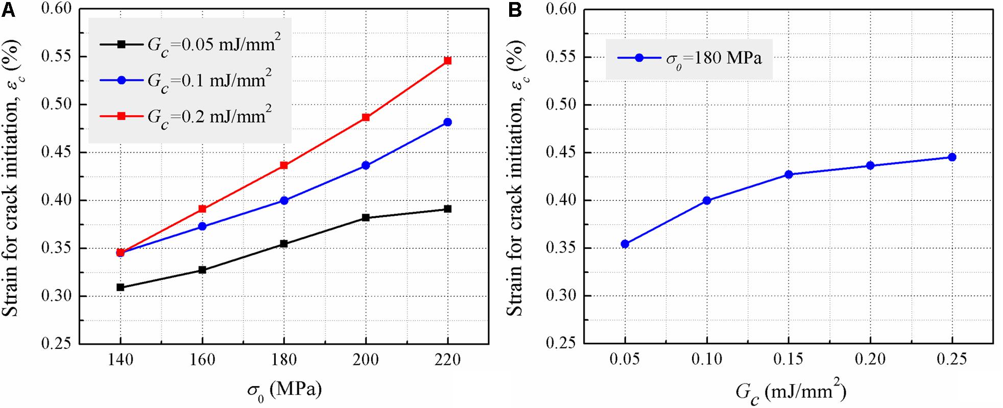
Figure 7. Effects of the fracture parameters, σ0 and Gc, on the strain for crack initiation, εc: (A) εc vs. σ0 for different Gc, (B) εc vs. Gc when σ0 = 180 MPa.
Results and Discussion
Experimental Observations
Figure 8 displays the experimental results, including in situ observations of the surface crack evolution and cross-sectional morphologies of vertical and interfacial cracks. As seen in Figures 8a–c, the first visible surface crack was found in the Cr coating when the tensile strain (ε) reached 0.4%. As the tensile strain increased, new surface cracks were continuously generated between two adjacent cracks, leading to an increase in the crack density. These multi-cracks were parallel to one another and vertical to the tensile direction. Subsequently, almost no new surface cracks were formed, and the crack density tended to be stable with increasing tensile strain; however, the cracks continued to darken, which indicates that the crack opening displacement (COD) became larger.
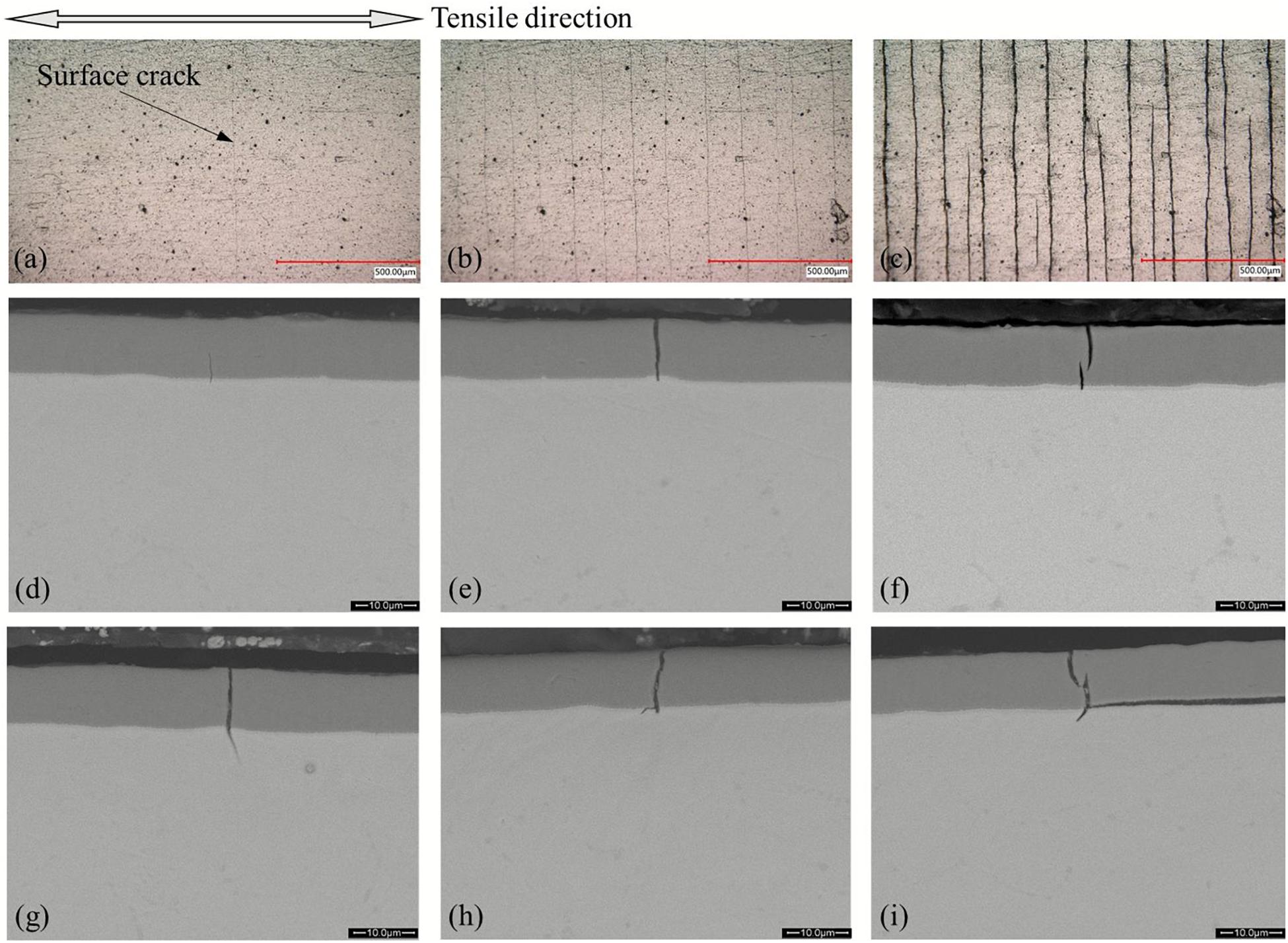
Figure 8. Cracking behaviors of the Cr-coated Zr-4 substrate under tension: in situ observations of the surface crack evolution at (a) ε = 0.4%, (b) ε = 1.32%, and (c) ε = 11.1%, and cross-sectional morphologies of cracks at various strains ranging from 3 to 10% showing (d) a vertical crack that initiated from the interface, (e) a vertical crack that penetrated through the coating thickness, (f) two vertical cracks initiated from both the interface and surface, (g) a vertical crack that penetrated to the substrate, (h) an interfacial crack that initiated from a vertical crack tip, and (i) cracks that not only penetrated to the substrate but also propagated along the interface.
To understand the initiation and propagation behavior of cracks on the surface of the coating, the cross-section morphologies at various strains were observed, as shown in Figures 8d–i. Vertical surface cracks were found that initiated in different areas. In most areas, vertical cracks were generated from the interface and propagated to the surface (see Figure 8d), which might be driven by the stress concentration at the interface caused by the large differences in the elastic modulus and plastic deformation between the Cr coating and the Zr alloy substrate. Further analysis and explanation will be presented in the following section using the results of the finite element simulation. In some areas, vertical cracks were also found that initiated from the surface (see Figure 8f), which might be due to local stress concentration caused by impurities or defects present on the coating surface.
Furthermore, after the vertical cracks penetrated through the coating thickness, they continued to propagate along different paths under continuous tension. In most areas, vertical cracks penetrated through the coating to the substrate (see Figure 8g), while few vertical cracks propagated along the interface (see Figure 8h), which reflected the weak interfacial adhesion in these local areas. In some areas, cracks not only penetrated to the substrate but also propagated along the interface (see Figure 8i). The competition between the mechanisms causing vertical and interfacial cracking was highly dependent on the magnitude of the fracture toughness of the Cr coating and the interfacial fracture toughness between the Cr coating and the substrate.
Plastic Deformation and Stress Analysis
The plastic deformation behavior of the coating system without considering cracking is presented first. Figure 9 displays the distributions of stress components, Sxx, Syy, and Sxy, in the coating-substrate system at ε = 0.4%. Clearly, the stress components in both the coating and the substrate were non-uniformly distributed along the x direction, and the Syy and Sxy were non-zero in large areas. These results were quite different from those calculated by a macro-scale FEM that considered isotropic material properties. The different mechanical behaviors of grains with different orientations led to this non-uniform distribution. In addition, the stress distribution near the interface showed a remarkable jump from the substrate to the coating, which was highly related to the difference in the mechanical properties of the two crystal structures (BCC structure for the Cr coating and HCP structure for the Zr-4 substrate) and deformation mismatch between the coating and the substrate. The grain-induced local stress concentration would promote earlier crack initiation under tension.
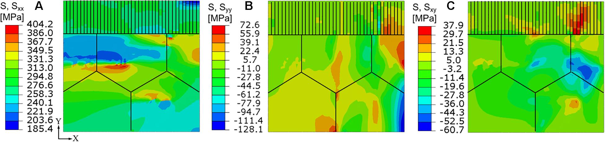
Figure 9. Distributions of stress components in the coating-substrate system at ε = 0.4%: (A) Sxx, (B) Syy, and (C) Sxy.
As shown in Figure 9, the stresses were different along the directions vertical and parallel to the tensile direction. To analyze the stress distribution in detail, a reference coordinate system was defined, as shown in Figure 10. The x-axis was parallel to the tensile direction, and the grains in the Cr coating were numbered from left to right as No. 0 to No. 40. The y-axis was parallel to the coating thickness such that the interface was located at y = 0 μm, and the coating surface was located at y = 10 μm. The stress components, Sxx and Syy, which were the driving forces for vertical and interfacial cracks, respectively, are the primary focus in the following discussion.
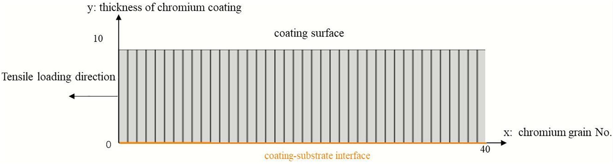
Figure 10. Coordinate system of the coating (substrate is underneath the coating).
Because the stresses in various grains in the coating were non-uniform, a detailed analysis of the Sxx distributions along the y direction for different grains (i.e., different x) was performed, as shown in Figure 11. No obvious decrease in Sxx were found along x direction. The stress presented a different distribution among grains because of the different crystal orientations in the adjacent grains. Their deformation abilities along the tensile direction were different, as derived from the Schmidt law. Figure 12 shows the Sxx distribution at the interface and the corresponding rotation angles (φ1, which can represent the grain orientations) around the z-axis in a laboratory coordinate for different grains in the Cr coating. For different grains, the interfacial stress varied from a minimum value of 247 MPa to a maximum value of 312 MPa. The significant variation in the stress is quite different from the results calculated by an isotropic constitutive model in which the stress was independent of the position along the x direction. For the CPFEM, the difference in the Schmidt factor for different Cr grains can rationalize the non-uniform stress distribution. The location where Sxx reached the maximum value could be the most preferential site for vertical crack formation.
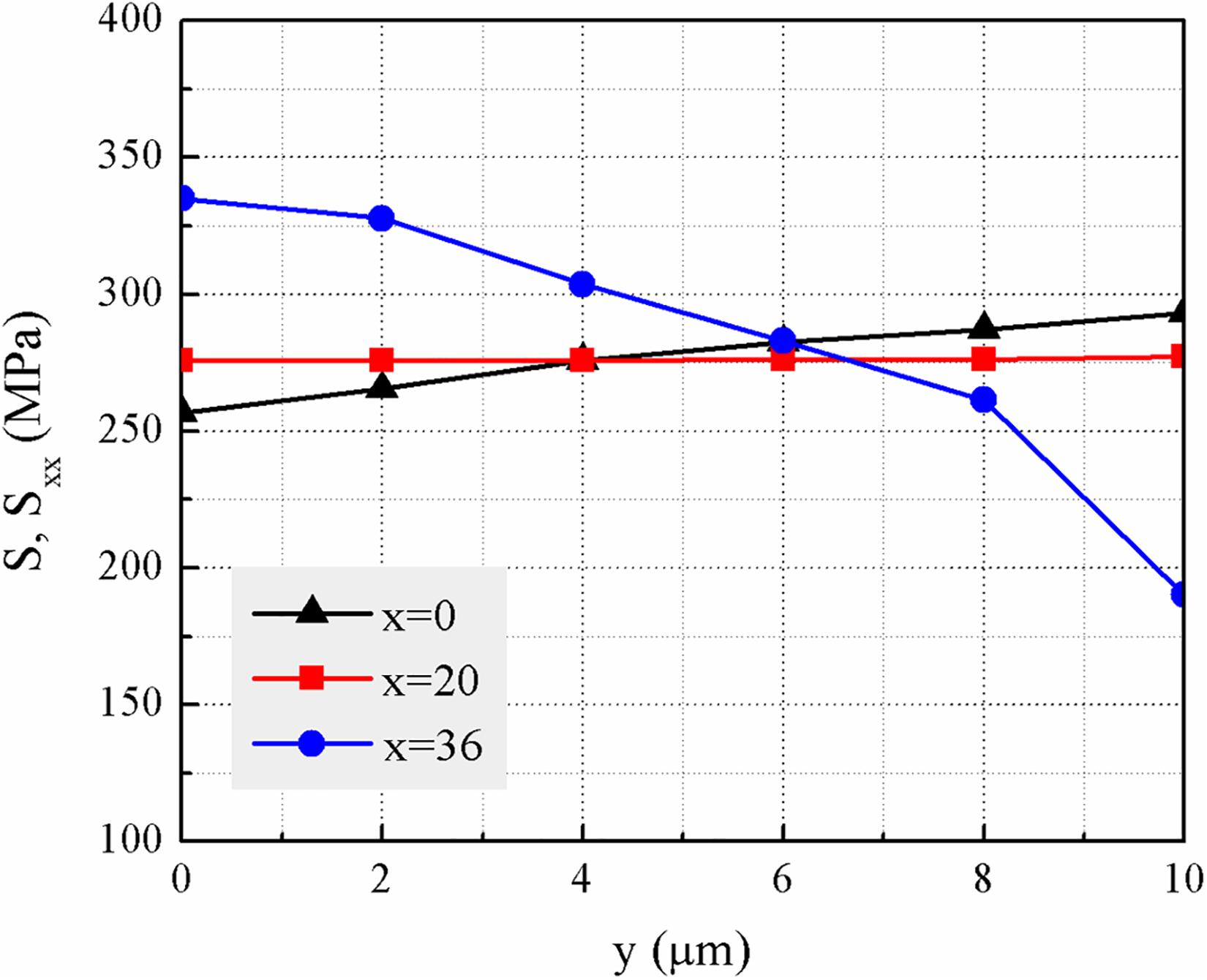
Figure 11. Sxx distributions along the y direction for different grains in the Cr coating when the tensile strain ε reached 0.4%. Note that x = 0 indicates grain No. 0, and x = 36 indicates grain No. 36.
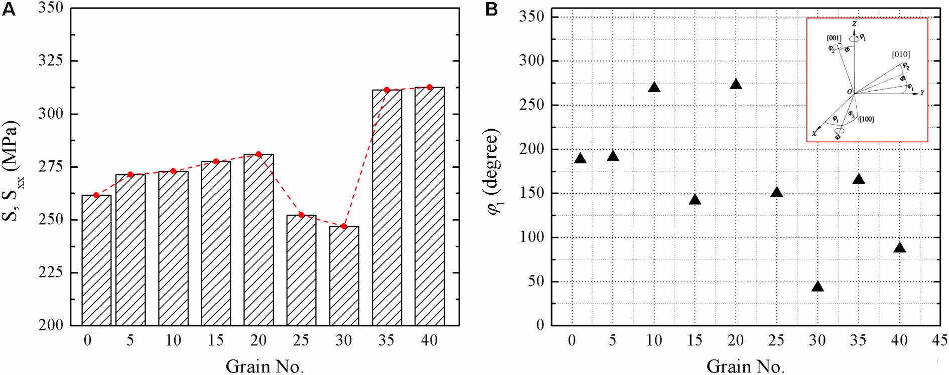
Figure 12. (A) Sxx at the interface between the coating and the substrate and (B) the corresponding rotation angles around the z-axis in a laboratory coordinate for different grains in the Cr coating when the tensile strain reached 0.4%.
Because interfacial cracks were also found in the tensile test, the driving force, i.e., Syy, was also analyzed. Figure 13 shows Syy at the interface for different grains in the Cr coating. It is worth noting that for an isotropic constitutive model, Syy should be zero for different x and y in the coating because no external loading is applied along the y direction. However, for the CPFEM, Syy in the coating varied greatly from -10 to 45 MPa in different positions, which was caused by the different crystal orientations of the Cr grains and the deformation mismatch between the coating and the substrate. As shown in Figure 13, Syy near the interface showed the largest change due to the deformation of the substrate. Near the coating surface, Syy in the coating tended to be nearly zero. The stress Syy showed tensile value at the interface, which may raise the possibility of initiation of interfacial cracks.
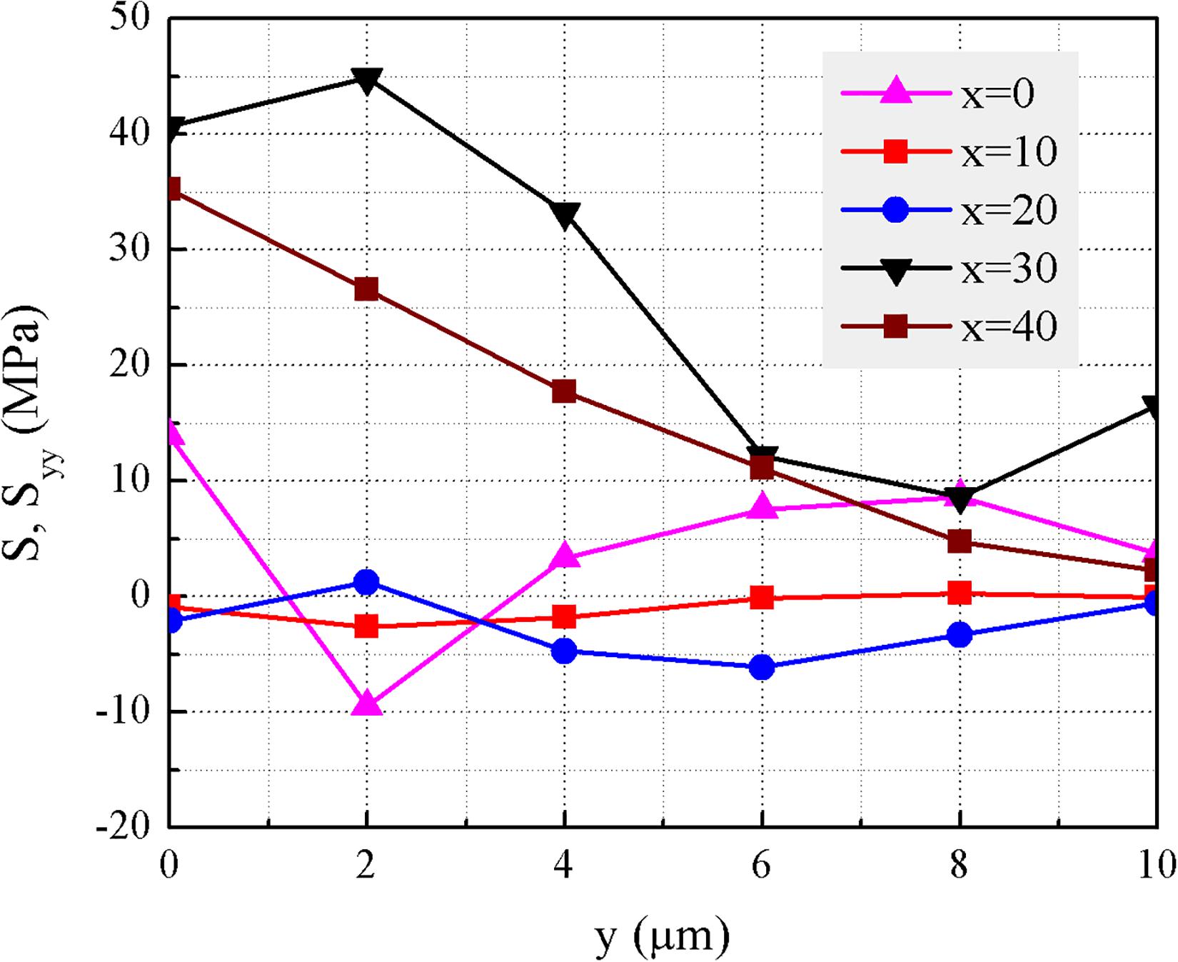
Figure 13. Syy distributions along the y direction for different grains in the Cr coating when the tensile strain ε reached 0.4%.
Tensile Cracking Behavior
During tensile tests, vertical cracks initiated and propagated through the coating thickness with increasing tensile strain, as shown in Figure 7. The cracking behavior in the Cr coating is directly related to the stress evolution with tensile strain. In turn, the formation of the crack redistributes the local stresses. To analyze this phenomenon, the initiation and propagation of vertical cracks in the Cr coating was simulated using a CZM, and the results of stress and crack evolutions under different tensile strains are displayed in Figure 14. As shown in Figures 14A,D, when ε reached 0.25%, although a crack had not yet formed, damage had already initiated and accumulated in the cohesive elements. The degradation in the cohesive zone led to local stress and strain concentration in the substrate near the interface. As shown in Figures 14B,E, the vertical crack began to form in the Cr coating when ε reached 0.25%, which indicates that the damage value in the cohesive elements reached one, and the relevant elements were deleted to form the crack surface. Once initiated, the vertical crack passed through the coating thickness rapidly to form a macro crack. Comparing Figure 9 and Figure 14B, the stress distribution changed considerably with the formation of the vertical crack. In particular, in the substrate, an area of stress concentration formed near the interface, passing through two adjacent Zr grains. In the Cr coating, the stress near the coating surface relaxed greatly in the region adjacent to the crack surface, while the stress near the interface increased considerably because of the crack tip. As the tensile strain increased, the vertical crack broadened, and the stress and strain concentrations increased considerably (see Figures 14C,F). Once the stress in the substrate reached a critical value, the vertical crack penetrated the substrate along the direction marked by the arrows in Figures 14C,F. The predicted crack deflection was consistent with the experimental observation shown in Figure 8.
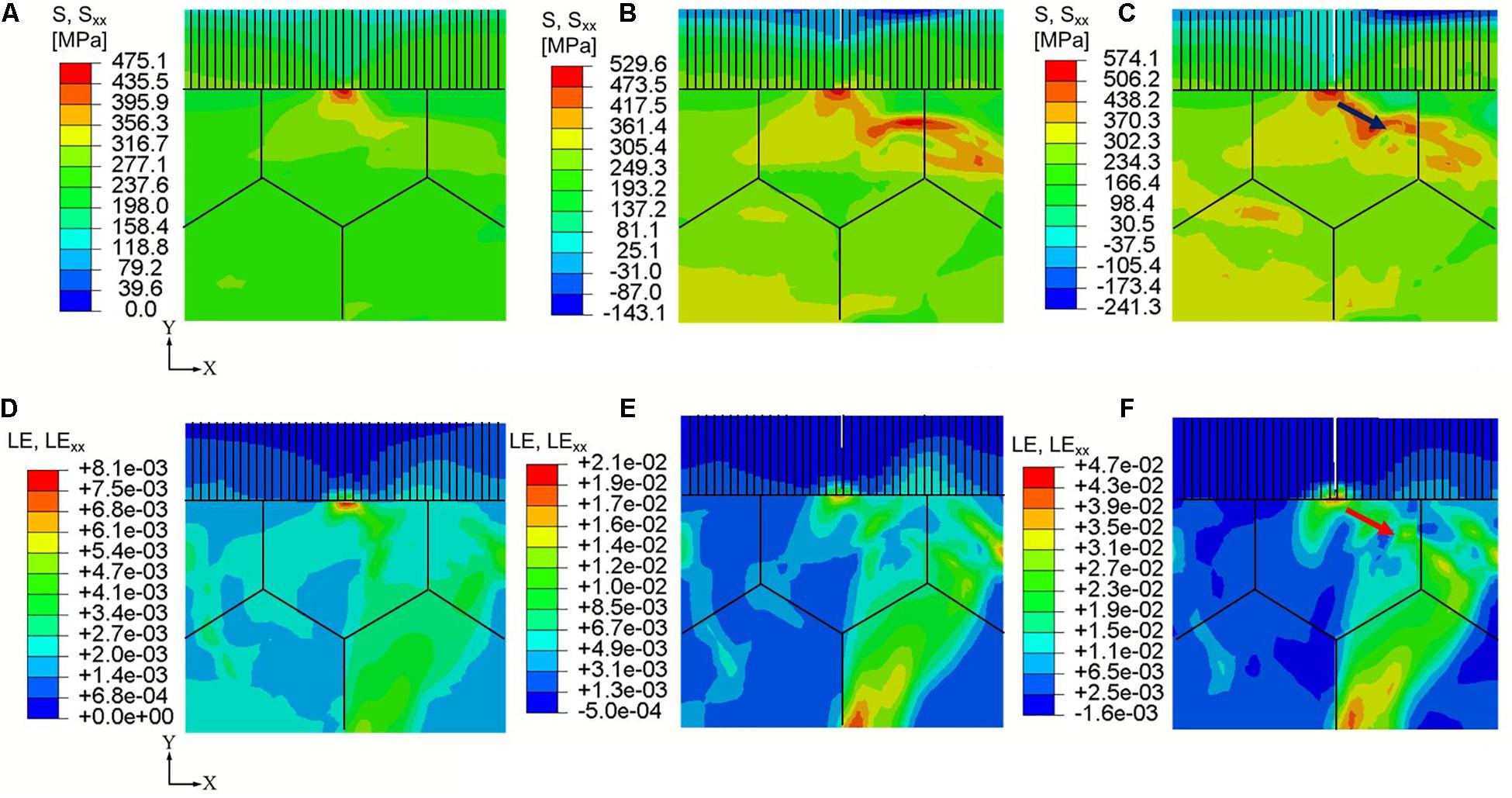
Figure 14. Evolution of the stress (Sxx) and strain (LExx) distributions with increasing tensile strain: (A,D) ε = 0.25%, (B,E) ε = 0.4%, and (C,F) ε = 1.0%.
Crack formation can also affect the stress–strain curve of the coating–substrate system. As shown in Figure 15, the engineering stress–strain curve changed markedly, particularly during the early period of tension. After the vertical cracks formed, the stress declined slightly when the strain increased from 0.4 to 0.65%, which was caused by stress relaxation with crack propagation. Once the vertical crack penetrated through the coating thickness, it was hindered by the substrate and stopped at the interface. When ε > 0.65%, the stress increased slowly and smoothly with increasing tensile strain.
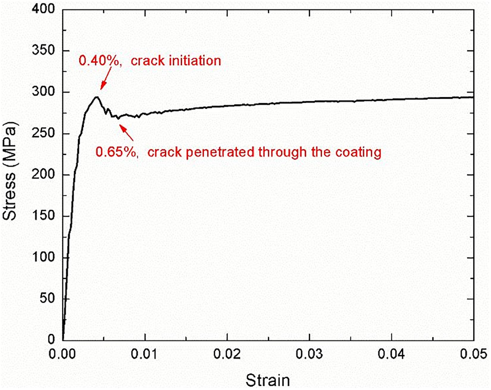
Figure 15. Engineering stress–strain curve of the Cr-coated Zr substrate system when considering vertical cracking behavior.
It is noted that the high stress concentration located at the crack tip may result in continuous crack propagation with a large tensile strain. As discussed previously, two propagation paths were possible: along the original crack direction (i.e., perpendicular to the loading direction), and along the interface between the coating and the substrate. The competition between the vertical and interfacial cracking mechanisms is controlled by the fracture parameters, such as the fracture strength and toughness of the coating and the substrate, and the interfacial fracture toughness. Further experiments and finite element calculations of these competing mechanisms will be developed in the future studies to build a strength assessment method for the ATF coating system.
Conclusion
The plastic deformation and cracking behavior of the Cr-coated Zr-4 cladding system were investigated by combining in situ mechanical tests and crystal plasticity finite element simulation. The main conclusions are summarized as follows:
(1) Based on in situ observation, the first surface crack appeared in the Cr coating with a tensile strain of 0.4%, and the crack density increased with the tensile strain. Vertical cracks generally initiated from the interface and penetrated through the coating thickness. Besides, a few interfacial cracks also initiated from the vertical crack tips due to the large local stress concentration.
(2) Based on the crystal plasticity simulation, the stress distributions in both the Cr coating and the Zr-4 substrate were non-uniform, which was quite different from those predicted by an isotropic constitutive model. The different mechanical behaviors and crystal orientations in different grains led to these non-uniform distributions. In addition, both Sxx and Syy showed concentration at the interface, which were responsible for the driving forces of vertical and interfacial cracking, respectively.
(3) Compared with the case without considering cracking, the stress in both the Cr coating and the Zr-4 substrate redistributed evidently with the formation of a vertical crack. When the vertical crack penetrated through the coating to reach the interface, large stress and strain concentrations were formed, particularly in the substrate, which was responsible for the failure process of the coating-substrate system.
Data Availability Statement
The original contributions presented in the study are included in the article/supplementary material, further inquiries can be directed to the corresponding author.
Author Contributions
XM: conceptualization, supervision, writing—original draft preparation, writing—reviewing and editing, and funding acquisition. WZ: investigation and visualization. ZC: methodology and validation. DY: investigation. JJ: methodology, data curation, visualization, writing—original draft preparation, and writing—reviewing and editing. LS and HZ: investigation and formal analysis. JT: validation. All authors agreed to be accountable for the content of the work.
Funding
This project was supported by the Guangdong Major Project of Basic and Applied Basic Research (2019B030302011), National Natural Science Foundation of China (Grant Nos. U2032143, 11902370, and 52005523), International Sci & Tech Cooperation Program of Guangdong Province (2019A050510022), Key-Area Research and Development Program of GuangDong Province (2019B010943001 and 2017B020235001), China Postdoctoral Science Foundation (2019M653173 and 2019TQ0374), Guangdong Education Department Fund (2016KQNCX005), and Fundamental Research Funds for the Central Universities (19lgpy304).
Conflict of Interest
The authors declare that the research was conducted in the absence of any commercial or financial relationships that could be construed as a potential conflict of interest.
References
Agnew, S. R., Yoo, H. M., and Tome, C. N. (2001). Application of texture simulation to understanding mechanical behavior of Mg and solid solution alloys containing Li or Y. Acta Mater. 49, 4277–4289. doi: 10.1016/s1359-6454(01)00297-x
Brachet, J. C., Idarraga-Trujillo, I., Le Flem, M., Le Saux, M., Vandenberghe, V., and Urvoy, S. (2019). Early studies on Cr-Coated Zircaloy-4 as enhanced accident tolerant nuclear fuel claddings for light water reactors. J. Nuclear Mater. 517, 268–285. doi: 10.1016/j.jnucmat.2019.02.018
Brachet, J. C., Rouesne, E., Ribis, J., Guilbert, T., and Pouillier, E. (2020). High temperature steam oxidation of chromium-coated zirconium-based alloys: kinetics and process. Corrosion Sci. 167:108537. doi: 10.1016/j.corsci.2020.108537
He, X., Tian, Z., Shi, B., Xu, X., Meng, C., Dang, W., et al. (2019). Effect of gas pressure and bias potential on oxidation resistance of Cr coatings. Ann. Nuclear Energy 132, 243–248. doi: 10.1016/j.anucene.2019.04.038
Hill, R., and Rice, J. R. (1972). Constitutive analysis of elastic-plastic crystals at arbitrary strain. J. Mech. Phys. Solids 20, 401–413. doi: 10.1016/0022-5096(72)90017-8
Holzwarth, U., and Stamm, H. (2002). Mechanical and thermomechanical properties of commercially pure chromium and chromium alloys. J. Nuclear Mater. 300, 161–177. doi: 10.1016/s0022-3115(01)00745-0
Hutchinson, J. W. (1976). Bounds and self-consistent estimates for creep of polycrystalline materials. Proc. R. Soc. Lond. Math. Phys. Sci. 348, 101–127. doi: 10.1098/rspa.1976.0027
Jiang, J. S., Wang, W., Zhao, X., Liu, Y., and Xiao, P. (2018). Numerical analyses of the residual stress and top coat cracking behavior in thermal barrier coatings under cyclic thermal loading. Eng. Fract. Mech. 196, 191–205. doi: 10.1016/j.engfracmech.2018.04.031
Jiang, J. S., Zhai, H. L., Gong, P. F., Zhang, W. J., He, X. J., Ma, X. F., et al. (2020). In-situ study on the tensile behavior of Cr-coated zircaloy for accident tolerant fuel claddings. Surf. Coat. Tech. 394:12547.
Jiang, P., Fan, X., Sun, Y., Li, D., and Wang, T. (2017). Competition mechanism of interfacial cracks in thermal barrier coating system. Mater. Des. 132, 559–566. doi: 10.1016/j.matdes.2017.07.018
Kim, H. G., Kim, I. H., Jung, Y. I., Park, D. J., Park, J. Y., and Koo, Y. H. (2015). Adhesion property and high-temperature oxidation behavior of Cr-coated Zircaloy-4 cladding tube prepared by 3D laser coating. J. Nuclear Mater. 465, 531–539. doi: 10.1016/j.jnucmat.2015.06.030
Lee, E. H. (1969). Elastic-plastic deformation at finite strains. J. Appl. Mech. 36, 1–6. doi: 10.1115/1.3564580
Ma, X., Zhai, H. L., Meng, F. Q., Jiang, J. S., He, X. J., Hu, Y. Y., et al. (2021). Benefit or harm of accident tolerant coatings on the low-cycle fatigue properties of Zr-4 cladding alloy: in-situ studies at 400°C. J. Nuclear Mater. 545:152651. doi: 10.1016/j.jnucmat.2020.152651
Maier, B. R., Garcia-Diaz, B. L., Hauch, B., Olson, L. C., Sindelar, R. L., and Sridharan, K. (2015). Cold spray deposition of Ti2AlC coatings for improved nuclear fuel cladding. J. Nuclear Mater. 466, 712–717. doi: 10.1016/j.jnucmat.2015.06.028
Meng, C., Yang, L., Wu, Y., Tan, J., Dang, W., He, X., et al. (2019). Study of the oxidation behavior of CrN coating on Zr alloy in air. J. Nuclear Mater. 515, 354–369. doi: 10.1016/j.jnucmat.2019.01.006
Paul, V. H. (1978). Simulation of the rolling and shear texture of brass by the Taylor theory adapted for mechanical twinning. Acta Metall. 26, 591–604. doi: 10.1016/0001-6160(78)90111-6
Peirce, D., Asaro, R. J., and Needleman, A. (1982). An analysis of nonuniform and localized deformation in ductile single crystals. Acta Metall. 30, 1087–1119. doi: 10.1016/0001-6160(82)90005-0
Raabe, D., Wang, Y., and Roters, F. (2005). Crystal plasticity simulation study on the influence of texture on earing in steel. Comput. Mater. Sci. 34, 221–234. doi: 10.1016/j.commatsci.2004.12.072
Tallman, D. J., Yang, J., Pan, L., Anasori, B., and Barsoum, M. W. (2015). Reactivity of Zircaloy-4 with Ti3SiC2 and Ti2AlC in the 1100–1300° C temperature range. J. Nuclear Mater. 460, 122–129. doi: 10.1016/j.jnucmat.2015.02.006
Tang, C., Stueber, M., Seifert, H. J., and Steinbrueck, M. (2017). Protective coatings on zirconium-based alloys as accident-tolerant fuel (ATF) claddings. Corrosion Rev. 35, 141–165. doi: 10.1515/corrrev-2017-0010
Terrani, K. A. (2018). Accident tolerant fuel cladding development: promise, status, and challenges. J. Nuclear Mater. 501, 13–30. doi: 10.1016/j.jnucmat.2017.12.043
Terrani, K. A., Parish, C. M., Shin, D., and Pint, B. A. (2013). Protection of zirconium by alumina-and chromia-forming iron alloys under high-temperature steam exposure. J. Nuclear Mater. 438, 64–71. doi: 10.1016/j.jnucmat.2013.03.006
Tomé, C. N., Ricardo, A., and Kocks, U. F. (1991). A model for texture development dominated by deformation twinning: application to zirconium alloys. Acta Metall. Mater. 39, 2667–2680. doi: 10.1016/0956-7151(91)90083-d
Usui, T., Sawada, A., Amaya, M., and Suzuki, A. (2015). SiC coating as hydrogen permeation reduction and oxidation resistance for nuclear fuel cladding. J. Nuclear Sci. Technol. 52, 1318–1322. doi: 10.1080/00223131.2015.1020901
Wang, Y., Tang, H., Han, X., Feng, W., Zhou, X., Peng, S., et al. (2018). Oxidation resistance improvement of Zr-4 alloy in 1000° C steam environment using ZrO2/FeCrAl bilayer coating. Surf. Coat. Tech. 349, 807–815. doi: 10.1016/j.surfcoat.2018.05.005
Wei, T., Zhang, R., Yang, H., Liu, H., Qiu, S., and Wang, Y. (2019). Microstructure, corrosion resistance and oxidation behavior of Cr-coatings on Zircaloy-4 prepared by vacuum arc plasma deposition. Corrosion Sci. 158:108077. doi: 10.1016/j.corsci.2019.06.029
Xu, F., Holt, R. A., and Daymond, M. R. (2009). Modeling texture evolution during uni-axial deformation of Zircaloy-2. J. Nuclear Mater. 394, 9–19. doi: 10.1016/j.jnucmat.2009.07.006
Yang, K., Lang, L., Deng, H., and Hu, W. (2018). Modified analytic embedded atom method potential for chromium. Modell. Simul. Mater. Sci. Eng. 26:065001. doi: 10.1088/1361-651x/aaca48
Zhong, W., Mouche, P. A., and Heuser, B. J. (2018). Response of Cr and Cr-Al coatings on Zircaloy-2 to high temperature steam. J. Nuclear Mater. 498, 137–148. doi: 10.1016/j.jnucmat.2017.10.021
Keywords: in situ test, crystal plasticity model, Cr coating, zirconium alloy, accident tolerant fuel cladding
Citation: Ma X, Zhang W, Chen Z, Yang D, Jiang J, Song L, Tu J and Zhai H (2021) Elastoplastic Deformation and Fracture Behavior of Cr-Coated Zr-4 Alloys for Accident Tolerant Fuel Claddings. Front. Energy Res. 9:655176. doi: 10.3389/fenrg.2021.655176
Received: 18 January 2021; Accepted: 12 April 2021;
Published: 24 May 2021.
Edited by:
Wenzhong Zhou, Sun Yat-sen University, ChinaReviewed by:
M. K. Samal, Bhabha Atomic Research Centre (BARC), IndiaDi Yun, Xi’an Jiaotong University, China
Copyright © 2021 Ma, Zhang, Chen, Yang, Jiang, Song, Tu and Zhai. This is an open-access article distributed under the terms of the Creative Commons Attribution License (CC BY). The use, distribution or reproduction in other forums is permitted, provided the original author(s) and the copyright owner(s) are credited and that the original publication in this journal is cited, in accordance with accepted academic practice. No use, distribution or reproduction is permitted which does not comply with these terms.
*Correspondence: Jishen Jiang, amlhbmdqc2gzQG1haWwuc3lzdS5lZHUuY24=