 Xiaoxiao Mao1†
 Xiaobin Jian1†Jingyu Zhang1†Feng Yan1
 Shurong Ding1*Yongzhong Huo1Haoyu Wang2*Lin Zhang2Yuanming Li2
- 1Department of Aeronautics and Astronautics, Institute of Mechanics and Computational Engineering, Fudan University, Shanghai, China
- 2Science and Technology on Reactor System Design Technology Laboratory, Nuclear Power Institute of China, Chengdu, China
To obtain the optimized fuel performance, the effects of U-Mo irradiation creep rate coefficient on the thermo-mechanical behavior of a fuel assembly are investigated. In this study, three cases of creep rate coefficient are considered. The distribution and evolution results of temperature, displacement, stress/strain and fuel foil micro-structure are analyzed. The simulation results indicate that with the increase of creep rate coefficient 1) the temperature field in the fuel assembly changes slightly; 2) the maximum out-of-plane displacements in the side plates decrease slightly; the maximum out-of-plane displacements in the fuel plates adjacent to the outside Al plates rise distinctly, induced by the enhanced bending deformation contributions; 3) the peak values of the first principal stresses and skeleton normal stresses in the fuel foils are reduced, while the through-thickness creep strains are enlarged; 4) with an increase of fuel creep rate coefficient from 500 × 10−22 mm3/(fission MPa) to 2,000 × 10−22 mm3/(fission·MPa), the maximum Von Mises stress in the fuel cladding decreases by ∼24% on the 308th day. This work is helpful for advanced fabrication and optimization design of U-Mo/Al fuel assemblies.
Introduction
To comply with nuclear non-proliferation requirements (Hanson and Diamond, 2011; Woolstenhulme and Nielson, 2011; Woolstenhulme et al., 2012; Robinson et al., 2013), low enriched uranium (LEU) fuels need to be utilized for advanced research and test reactors. Monolithic U-Mo fuels have been demonstrated to be attractive candidates because of their low neutron capture cross section, high uranium density, stable irradiation swelling performance (Burkes et al., 2009; Robinson et al., 2013; Mei et al., 2015; Newell et al., 2017). Rectangular fuel assemblies (Brown et al., 2013; Wu et al., 2017) can be made by connecting a number of U-Mo/Al monolithic fuel plates (Cheng et al., 2004; Perez et al., 2011; Robinson et al., 2013; Turkoglu et al., 2019) with an Al alloy frame, using the processing method of rolling-swage. In the reactor cores, dozens of fuel assemblies will be placed into specified positions, and control rod channels are retained among the fuel assemblies (Wu et al., 2017). The coolant channels exist between the fuel plates to keep the normal coolant flow (Baek et al., 2015; Fan et al., 2016; Guo et al., 2018; Ma et al., 2018), with the fission heat transferred timely (Cheng et al., 2004; Baek et al., 2015; Woolstenhulme et al., 2015). Under the in-service environments, different mechanisms are involved in the deformations of fuel assemblies (Deng et al., 2017), which will result in the variations of control rod channels and coolant channels. In order to achieve the optimization of a reactor design, it is necessary to develop theoretical models and conduct numerical simulation researches on the thermal-mechanical behavior of fuel assemblies, combined with experimental researches.
Complicated in-pile thermo-mechanical behavior appears in U-Mo/Al monolithic fuel assemblies (Miller et al., 2010; Kim et al., 2012; Deng et al., 2017), which mainly depends on the following contributions: 1) the deformations (Miller et al., 2010; Kim and Hofman, 2011; Kim et al., 2013; Meyer et al., 2014; Zhao et al., 2015) induced by irradiation swelling and creep of fuel foil (Kim et al., 2013; Kim and Hofman, 2011); 2) the plasticity and thermal creep performances of cladding (Yan et al., 2017; Jian et al., 2019a); 3) formation of porous fuel structure due to the fission-gas-resulted bubbles (Rest, 2010; Meyer et al., 2014); 4) the acceleration of fission gas swelling driven by grain recrystallization (Rest, 2010); 5) the degradations of thermo-mechanical properties and macroscale strength owing to the formed porous structure, pore pressure and the possible creep damage in the fuel foil (Rest, 2010; Robinson et al., 2008; Iltis et al., 2016; Yan et al., 2017; Salvato et al., 2018; Jian et al., 2019a; Schulthess et al., 2019); 6) the complex mechanical interactions across all the parts, including the fuel plates, the outside Al plates and the side plates (Deng et al., 2017). On one hand, the irradiation creep strains will relax the stresses in the fuel foils or the other parts. On the other hand, the high creep strains will result in creep damage and degradation of fuel strength (Iltis et al., 2016; Jian et al., 2019a). It is necessary to examine the effects of fuel creep performance on the thermal-mechanical behavior in U-Mo/Al fuel assemblies, which will supply a basis for advanced fuel design.
The thermo-mechanical behavior analysis for monolithic U-Mo/Al fuel plates can be found in the previous works (Kim et al., 2012; Kim et al., 2013; Jian et al., 2019a). A linear relation of equivalent creep strain rate with fission rate and Von Mises stress was generally adopted, namely
In this study, simulations of the thermo-mechanical coupling behavior are implemented for three fuel assemblies with respective U-Mo irradiation creep rates, and the corresponding effects on the results of temperature, deformation and stresses are obtained and analyzed, together with the influences on the fuel porosity, pore pressure and skeleton stresses (Jian et al., 2019b).
Finite Element Modeling
Finite Element Model
A typical fuel assembly made of sixteen U-Mo/Al monolithic fuel plates and an Al alloy frame is considered (Mao et al., 2021), as shown in Figure 1A, with the fuel plates assembled well into two grooved side plates through roll-swaging (Kim et al., 2014). The dimensions of fuel plates are 332.0 mm × 68.0 mm × 1.27 mm, and those of U-Mo fuel foil are 279.4 mm × 61.34 mm × 0.216 mm (Baek et al., 2015), as illustrated in Figure 1B. The coolant channels between two neighboring plates (Baek et al., 2015) can be found in Figure 1C, with a width of 2.95 mm. The sizes of grooved side plates are set as 332.0 mm × 75.96 mm × 6.5 mm (Baek et al., 2015).
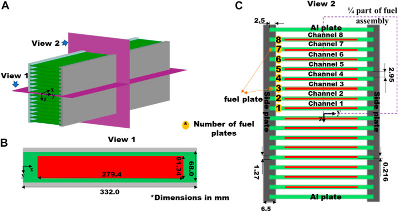
FIGURE 1. Model details in (A) Schematic view, (B) The View 1 and (C) The View 2 of the fuel assembly (all dimensions in mm) (Mao et al., 2021).
According to the fission density data (Brown et al., 2013) in Figure 2A, a linearly-distributed fission rate is fitted as
where
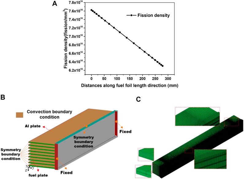
FIGURE 2. (A) The distribution of fission density along fuel foil length direction (Brown et al., 2013) after irradiation of 308 days and (B) The boundary conditions of FE model, and (C) The mesh in the fuel assembly.
With the symmetries in geometry, loads and boundary conditions of the considered fuel assembly, 1/4 part is established as the FE model in Figure 2B. Fixed displacement boundary conditions are applied on the two ends. In addition, the continuous conditions of displacement and temperature are considered on the formed interfaces. The temperature of coolant is set as 323 K (Cui et al., 2015), and the convection heat transfer boundary conditions are taken into account, with a heat transfer coefficient of
The Governing Equations and Solution Techniques for the Thermal-Mechanical Fields
Governing Equations
For the Temperature Field
The temperature field in the fuel assembly is governed by (Ding et al., 2009).
where
For the Mechanical Field
In this study, large deformation is considered, and the governing equations of the mechanical field can be expressed as
where
It should be mentioned that the total deformation rate consists of the deformation contributions of elasticity, irradiation creep and irradiation swelling for the fuel foil. The mechanistic fission gas swelling model has been used. The grain crystallization effect has been involved, and the bubble radius correlates with the grain-scale fission gas atom diffusion, detailed in Jian et al. (2019a); Jian et al., 2019b. For the Al alloy, the total deformation rate is composed of elasticity, creep and plasticity parts, with the models of Lame constants and creep the same as those in Jian et al. (2019b), with the plasticity model adopted from Jian et al. (2019a).
The fission-induced creep rate model is given as Yan et al. (2017).
where,
Solution Techniques for the Irradiation-Induced Thermal-Mechanical Fields
For the numerical implementation of the thermal-mechanical theoretical models on the commercial software ABAQUS, it is necessary to define the location-irradiation time-temperature dependent thermal-mechanical constitutive relations. The solution techniques in this study are similar to those in our previous works (Ding et al., 2009; Ding et al., 2009; Gong et al., 2013; Gong et al., 2014; Zhao et al., 2014; Cui et al., 2015; Zhao et al., 2016; Zhao et al., 2016; Kong et al., 2018). Here, the three-dimensional mechanical constitutive relation in an incremental form is briefly introduced as follows.
For a small time increment
where
In ABAQUS, based on the polar decomposition (Simulia and Fallis, 2013) for the deformation gradient increments, the values of the total logarithmic strain increments are calculated out for stress update. One should develop stress update algorithms and consistent stiffness modulus, with the other strain increment contributions involved, and then the subroutines of UMAT can be programmed to define the irradiation-induced complex mechanical constitutive relations. For the U-Mo fuel foil and Al alloy, the similar solution strategy as those in our previous works (Ding et al., 2009; Ding et al., 2009; Gong et al., 2013; Gong et al., 2014; Zhao et al., 2014; Cui et al., 2015; Zhao et al., 2015; Zhao et al., 2016; Zhao et al., 2016; Kong et al., 2018) is adopted in this study, and the developed models, algorithms and user-defined subroutines have been verified. Especially, with the mechanistic gaseous swelling model and irradiation creep model used for U-Mo fuels, the fuel foil thickness increments in a mini plate were calculated to match well with the experimental results (Jian et al., 2019a).
The Skeleton Stress Model
A porous structure of U-Mo fuel foils will be formed due to fission gas bubbles. The skeleton stress model (Jian et al., 2019a; Jian et al., 2019b) is incorporated into the finite element calculations, which depends on the bubble volume fraction
where
Results and Discussion
In this section, the simulation results of temperature, displacement and stress/strain for three U-Mo/Al plate-type fuel assemblies with different fuel creep rate coefficients are compared and analyzed. The view cuts and output paths are displayed in Figure 3.
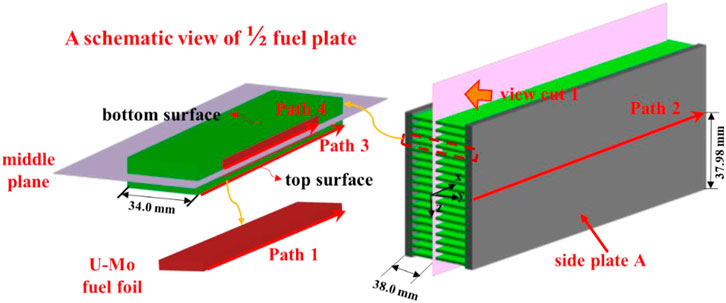
FIGURE 3. View cuts and typical output paths chosen in the fuel assembly (all dimensions in mm).
Effects of Fuel Creep Rate Coefficient on the Temperature and Displacement Fields
On the Temperatures in the Fuel Plates and Side Plates
As the same irradiation conditions are considered, the temperature fields in eight fuel plates are almost the same. Figure 4A gives the contour plot of temperature field in the fuel foil of Plate 8, after irradiation of 308 days for a creep rate coefficient of 500 × 10−22 mm3/(fission·MPa). It can be easily noted that a peak value of ∼377.8 K exists in the heavily irradiated region. To present the effect of U-Mo creep rate coefficient on the temperature field, Path 1 in Figure 3, on the fuel meat top surface of Plate 8, is chosen. Path 2 which goes through the maximum temperature point on the side plate is also selected in Figure 3. As no fission heat is generated in the outside Al plates, a temperature gradient is formed in the width direction of side plate A. As depicted in Figures 4C,D, the temperature results change slightly for the considered three creep rate cases.
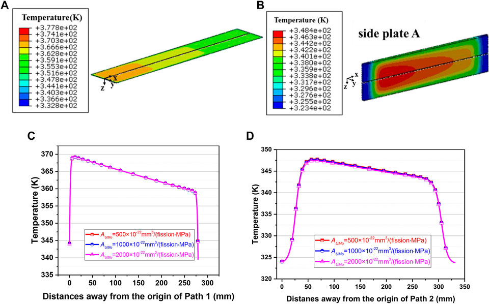
FIGURE 4. Contour plot of temperature field in (A) The fuel foil of Plate 8 and (B) The side plate A after irradiation of 308 days for a creep rate coefficient of 500 × 10−22 mm3/(fission·MPa), and the temperature results along (A) Path 1 and (D) Path 2 on the 308th day for three creep rate coefficients of 500 × 10−22 mm3/(fission·MPa), 1,000 × 10−22 mm3/(fission·MPa) and 2,000 × 10−22 mm3/(fission·MPa).
On the Displacements of Side Plates
The schematic design of the reactor core in Wu et al. (2017) indicates that narrow control rod channels exist among different fuel assemblies. The irradiation-induced space variations of these channels deserve attention. The out-of-plane displacements U2 of side plates directly affect the variations of control rod channels, and U2 depicts the displacement component in the y-direction, as shown in Figure 3. Figure 5A depicts the contour plot of displacement U2 in side plate A, after irradiation of 308 days for a creep rate coefficient of 500 × 10−22 mm3/(fission·MPa). The maximum displacement of ∼0.084 mm occurs in Path 2 of Figure 3. In Figure 5B, one can observe that the displacements of U2 show a trend of reduction as a whole, with the increase of creep rate coefficient. After irradiation of 308 days, the maximum displacement is ∼0.082 mm for a creep rate coefficient of 2,000 × 10−22 mm3/(fission·MPa), which is ∼2.4% smaller than that for 500 × 10−22 mm3/(fission·MPa). This indicates that the resultant forces from every fuel plate are slightly changed. It should be mentioned that the displacements of side plate mainly result from the bending deformations, driven by the forces from the fuel plates (Mao et al., 2021). Compared to the initial width of 1 cm (Cheng et al., 2004), the effects of out-of-plane displacements in the side plates can be ignored. It is noted that the displacement results are obtained with the two ends of fuel assembly constrained. The effects of creep rate coefficient might be varied under some other constraint conditions.
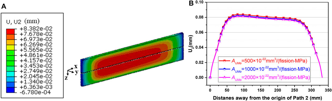
FIGURE 5. (A) Contour plot of displacement U2 in side plate A after irradiation of 308 days for a creep rate coefficient of 500 × 10−22 mm3/(fission·MPa) and (B) The corresponding results along Path 2 for various creep rate coefficients.
On the Displacements of Fuel Plates
To avoid flow blockage accident in research reactors (Baek et al., 2015), enough spaces of coolant channels must be guaranteed. As shown in Figure 1, the positions of bottom and top surfaces of fuel plates and outside Al plates can directly reflect the configuration of coolant channels. It should be noted that U3 denotes the displacement component in the z-direction, as displayed in Figure 3, which can be used to analyze the space variations of coolant channels. As displayed in Mao et al. (2021), the maximum out-of-plane displacements of Plate 8 are much larger than those of the other numbered fuel plates. In Figure 6, the contour plots of displacement U3 on the 308th day on the top and bottom surfaces of Plate 8 are given. It can be easily noted that the distributions of out-of-plane displacements on the top and bottom surfaces are asymmetry, especially for the U-Mo creep rate coefficient of 2,000 × 10−22 mm3/(fission·MPa). Besides, one can see from Figures 6A–C that the displacements will be locally enhanced for the creep rate coefficient of 2,000 × 10−22 mm3/(fission·MPa). In Yan et al. (2017); Jian et al. (2019a), the out-of-plane displacements on the top and bottom surfaces for a monolithic U-10Mo fuel plate were symmetric, where the contributions of displacement only result from the thickness increments of fuel foil. Here, the displacements of Plate 8 involve the contributions of the mechanical interactions of all the parts in the fuel assembly, including the contributions of bending deformations and thickness increments (Mao et al., 2021).
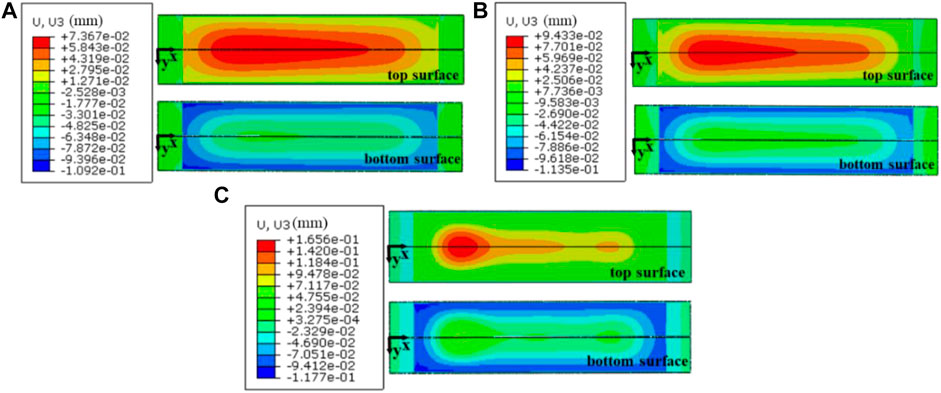
FIGURE 6. Contour plots of displacement U3 on the top and bottom surfaces of Plate 8 on the 308th day when the creep rate coefficients are (A) 500 × 10−22 mm3/(fission·MPa), (B) 1,000 × 10−22 mm3/(fission·MPa) and (C) 2,000 × 10−22 mm3/(fission·MPa).
Path 3 on the top surface of a fuel plate is shown in Figure 3. The displacement components of U3 along the similar paths can be found in Figure 7A, which are the results after irradiation of 308 days for different fuel plates and outside Al plates. The maximum out-of-plane displacement on the top surface of Plate 8 is 0.074 mm, which is larger than those in the other plates. For the creep rate coefficient of 500 × 10−22 mm3/(fission·MPa), the maximum displacements in the fuel plates decrease firstly, and then increase with the distances away from Plate 1. It can be noted that the displacement pattern of Plate 8 differs from those of the other fuel plates. Figure 7B gives the comparison of the Plate 8 displacement results of U3 along Path 3 on the 308th day for the three cases. When the creep rate coefficient increases from 500 × 10−22 mm3/(fission·MPa) to 2,000 × 10−22 mm3/(fission·MPa), the maximum out-of-plane displacement increases by ∼124%. In order to interpret the contributions of bending deformations, Path 4 in Plate 8 is chosen (shown in Figure 3), and the bending moments of
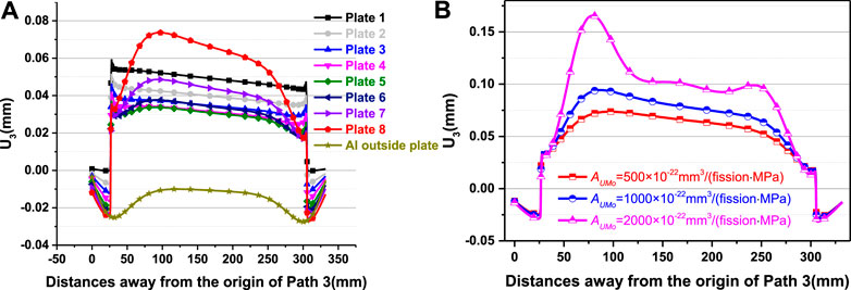
FIGURE 7. (A) The distribution of displacement U3 along Path 3 on the 308th day for a creep rate coefficient of 500 × 10−22 mm3/(fission·MPa) and (B) The displacement results of U3 along Path 3 in Plate 8 on the 308th day for the creep rate coefficients of 500 × 10−22 mm3/(fission·MPa), 1,000 × 10−22 mm3/(fission·MPa) and 2,000 × 10−22 mm3/(fission·MPa).
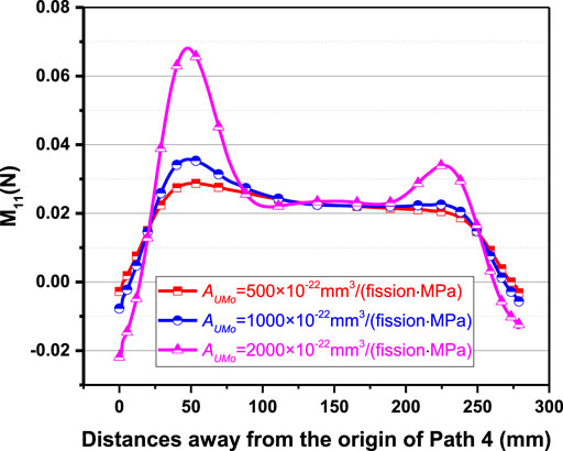
FIGURE 8. The results of the bending moment
From the results in Figures 7A, 9A, one can see that the thickness increments of Plate 1 mainly result from those of the fuel foil. The thickness increments at the foil edges are close to zero, although the irradiation swelling deformations tend to induce the increase of the fuel foil. Besides, a distinct local increase of the foil thickness can be found near the fuel foil edges. This deformation mechanism has been explained in our previous work (Jian et al., 2019a), which is attributed to the mutual interactions of irradiation swelling and creep. In Jian et al. (2019a), the simulation results of the thermal-mechanical behavior in a mini monolithic U-10Mo fuel plate were obtained, with the adopted theoretical models and solution strategies in this study. The calculated results of the fuel foil thickness matched well with the experimental data in Kim et al. (2013), as shown in Figure 9B. The local deformation phenomena in Figures 9A,B are consistent with each other.
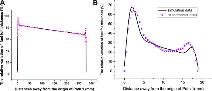
FIGURE 9. (A) The fuel foil thickness increments of Plate 1 along the length direction on the 308th day and (B) the results of fuel foil thickness increments in Jian et al. (2019a).
For the U-Mo creep rate coefficient of 2,000 × 10−22 mm3/(fission·MPa), it was found the smallest width existed at Channel 7 (Mao et al., 2021). To describe the variations of channel width directly, Figures 10A–D show the width evolution results of Channel 7. It is noted that the channel width of the point for a certain x-coordinate refers to the smallest value in the y-direction. One can see that the channel widths will be narrowed at locations with certain distances away from the two ends. Meanwhile, it can be easily noticed that the coolant channel becomes narrower with the increase of U-Mo creep rate coefficient, and it decreases with the irradiation time for every case. For the creep rate coefficients of 500 × 10−22 mm3/(fission·MPa) and 1,000 × 10−22 mm3/(fission·MPa), the coolant channel widths differ slightly in the x-coordinate interval from 25 to 300 mm. While, for the creep rate coefficient of 2,000 × 10−22 mm3/(fission·MPa), a position with a local minimum width is observed, with
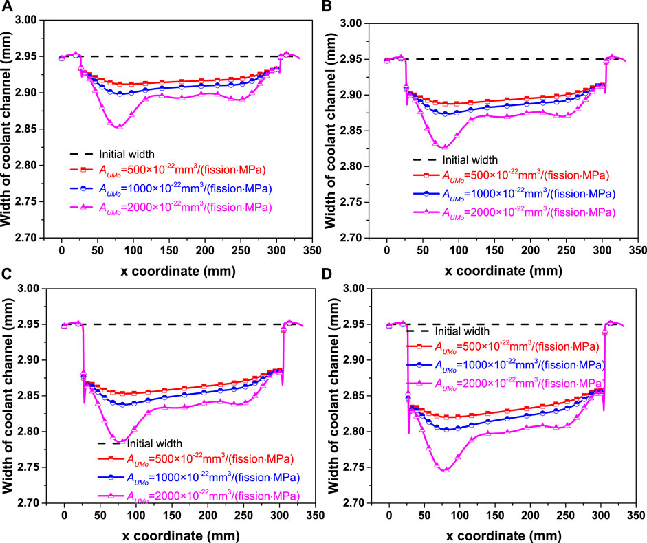
FIGURE 10. The width of coolant Channel 7 on the (A) 77th day, (B) 154th day, (C) 231th day and (D) 308th day for various creep rate coefficients.
Effects of Creep Rate Coefficient on the Multiscale Mechanical Behavior of Fuel Foils
On the First Principal Stresses and Irradiation Creep Strains
It was found in some post-irradiation examinations that cracks appeared in the fuel foil near the fuel foil/cladding interface (Meyer et al., 2014), which was explained to have relations with the first principal stresses of fuel foil (Jian et al., 2019a). For the three creep rate cases, the maximum values of the first principal stress all exist in the fuel foil of Plate 1. For 500 × 10−22 mm3/(fission·MPa), the contour plot of the first principal stresses after irradiation of 308 days is given in Figure 11. Relatively large tensile stresses can be found near the corners and edges of fuel foil, and the maximum value becomes ∼54.6 MPa. To analyze the effects of creep rate coefficient on the first principal stresses, Path 5 in the fuel foil of Plate 1 (as shown in Figure 11) is chosen to output results, which passes through the point of the maximum tensile stress.
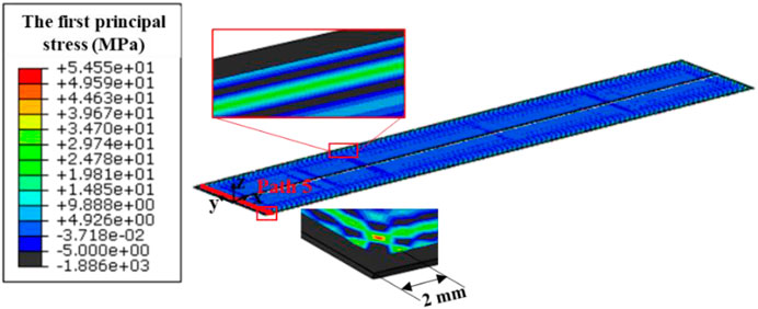
FIGURE 11. Contour plot of the first principal stresses in the fuel foil of Plate 1 on the 308th day for the creep rate coefficient of 500 × 10−22 mm3/(fission·MPa).
Figures 12A–D give the evolution results of the first principal stress and creep strain component along Path 5. Except for those near the two ends, the tensile stresses can be seen and larger values appear near the locations with ∼2 mm away from the two path ends. With the increase of creep rate coefficient from 500 × 10−22 mm3/(fission·MPa) to 2,000 × 10−22 mm3/(fission·MPa), the maximum tensile stress on the 308th day decreases by ∼25%, which is similar to that in Yan et al. (2019). After irradiation of 231 days, the maximum tensile stress is ∼58 MPa for 500 × 10−22 mm3/(fission·MPa), which is ∼34% greater than that for 2,000 × 10−22 mm3/(fission·MPa). As mentioned above, creep damages might occur to result in the reduction of the fuel foil strength, and then induce the fuel foil failure (Iltis et al., 2016; Meng and Wang, 2016). Comparing the through-thickness creep strain components in the fuel foil of eight fuel plates, one can obtain that relatively large values also take place in Plate 1. Figures 12A–D also display the evolution results of through-thickness creep strain component
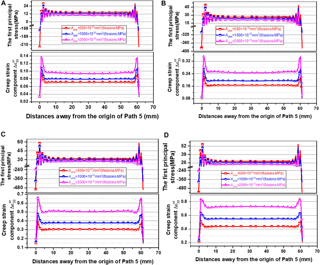
FIGURE 12. The evolution results of the first principal stress and creep strain component
On the Maximum Skeleton Stresses, Bubble Fractions and Bubble Pressures
Figures 13A,B show the contour plot of the maximum skeleton normal stresses after irradiation of 308 days in the porous fuel foils of Plate 1 and Plate 8. The maximum skeleton normal stress becomes 97.5 MPa in the fuel foil of Plate 1, which is 9.2% greater than that in Plate 8. As described in Eq. 8, the maximum skeleton normal stress depends on the first principal stress, bubble volume fraction, bubble radius and pressure. As the same irradiation condition is considered in the three cases, the results of bubble volume fraction in % and bubble pressure are almost the same. As depicted in Figure 13C, the maximum bubble volume fraction is up to 12.8% in the heavily irradiated region of fuel foil. In Jian et al. (2019a), it was found that the bubble volume fraction increased with the fission density and was speeded up after grain recrystallization. The values of bubble pressure differ slightly, as described in Figure 13D. After irradiation of 308 days, the maximum bubble pressure is up to 99.7 MPa.
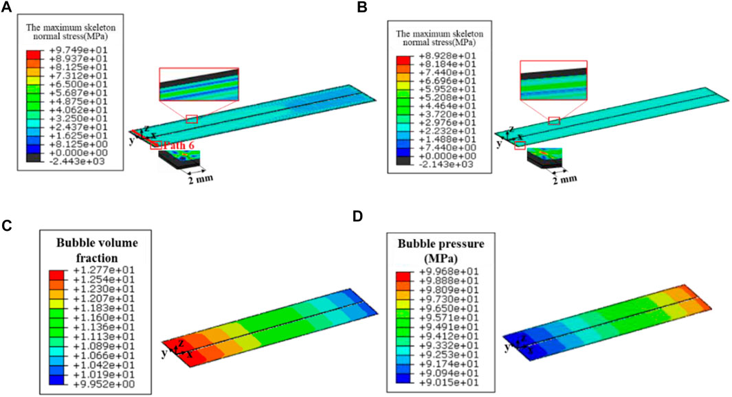
FIGURE 13. Contour plot the maximum skeleton normal stress in (A) Plate 1 and (B) Plate 8 fuel foil on 308th day when creep rate coefficient is 500 × 10−22 mm3/(fission·MPa), and the contour plot of (C) Bubble volume fraction and (D) Bubble pressure in fuel foil on 308th day when creep rate coefficient is 500 × 10−22 mm3/(fission·MPa).
In Figure 14, the maximum skeleton normal stresses at different irradiation time can be found, which are the results along Path 6 in the fuel foil of Plate 1. It should be noted that Path 6 has the point with the peak value. The maximum values exist at the location with a distance of ∼2 mm away from the two path ends, the same as the peak value location of the first principal stress. With the increase of irradiation time, the tensile stresses are enlarged as a whole. After irradiation of 308 days, a peak value of 97.5 MPa is obtained for the creep rate coefficient of 500 × 10−22 mm3/(fission·MPa), which is ∼23.3% higher than that for 2,000 × 10−22 mm3/(fission·MPa). This indicates that the mechanical interactions between the fuel foil and cladding become weaker with the increase of creep rate coefficient. While, it can’t be inferred that a larger creep rate coefficient is advantageous for the structural integrity of fuel foil, because the failure criterion should be developed with the combinations of the skeleton stresses and the irradiation creep degraded skeleton strength.
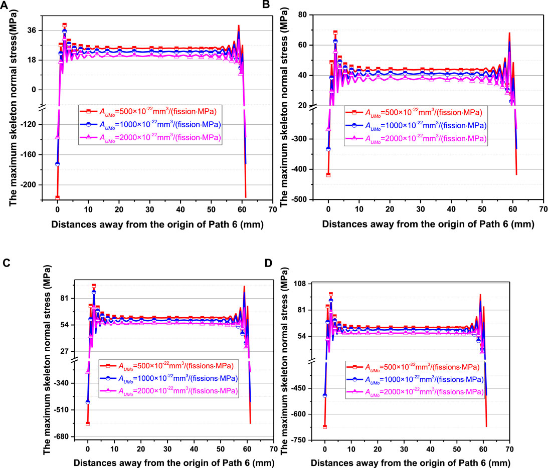
FIGURE 14. The skeleton normal stress along Path 6 in the fuel foil of Plate 1 on the (A) 0.0011th day, (B) 115.5th day, (C) 231th day and (D) 308th day for the creep rate coefficients of 500 × 10−22 mm3/(fission·MPa), 1,000 × 10−22 mm3/(fission·MPa) and 2,000 × 10−22 mm3/(fission·MPa).
Effects of Fuel Foil Creep Rate Coefficient on the Von Mises Stresses of Cladding
In this section, the Von Mises stresses in the cladding will be discussed, due to the fact that fuel cladding is the first safety barrier. In the considered fuel assembly, the maximum Von Mises stress of cladding takes place in the fuel plates closer to Al outside plates (Mao et al., 2021). Figure 15 gives the contour plot of Von Mises stress on the 308th day in the cladding of Plate 8, for the creep rate coefficient of 500 × 10−22 mm3/(fission·MPa). The maximum Von Mises stress of 258 MPa appears near the corner of fuel foil. One can find from Marchbanks (1995) that the tensile strength value becomes 320 MPa at a test temperature of 344 K, which is the temperature of the maximum stress point. For 500 × 10−22 mm3/(fission·MPa), it can be obtained that the cladding for all the fuel plates is relatively safe after irradiation of 308 days. To present the effects of creep rate coefficient, Path Seven in the cladding is chosen to output results, which passes through the point with the maximum Von Mises stress.
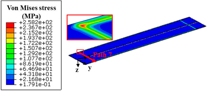
FIGURE 15. Contour plot of Von Mises stress in the cladding of Plate 8 on the 308th day for the creep rate coefficient of 500 × 10−22 mm3/(fission·MPa).
Figure 16 gives the evolution results of Von Mises stress along Path 7 for three cases. The Von Mises stresses can be seen to increase with irradiation time, and decrease obviously with the increase of fuel creep rate. After irradiation of 308 days, the maximum Von Mises stress for 2000 × 10−22 mm3/(fission·MPa) is ∼24% smaller than that for 500 × 10−22 mm3/(fission·MPa). With the increase of creep rate coefficient, the stress relaxation effects are enhanced in the fuel foil, and the mechanical interactions between the fuel foil and the cladding are weakened.
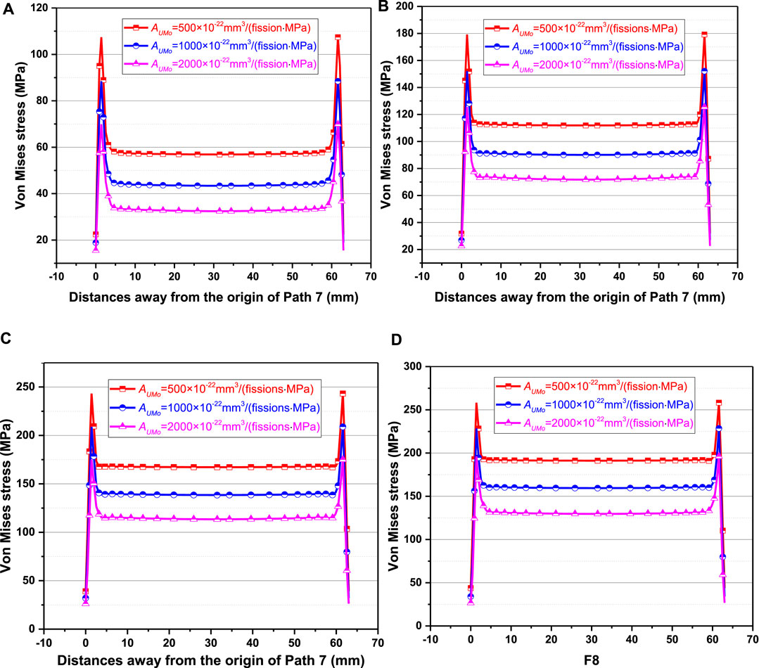
FIGURE 16. The evolution results of Von Mises stress along Path 7 on the (A) 0.0011th day, (B) 115.5th day, (C) 231th day and (D) 308th day for the creep rate coefficients of 500 × 10−22 mm3/(fission·MPa), 1,000 × 10−22 mm3/(fission·MPa) and 2,000 × 10−22 mm3/(fission·MPa).
Conclusion
In this study, the three-dimensional thermo-mechanical variables in a U-Mo/Al monolithic fuel assembly constrained at the two ends are obtained for the fuel foil creep rate coefficients of 500 × 10−22 mm3/(fission·MPa), 1,000 × 10−22 mm3/(fission·MPa) and 2000 × 10−22 mm3/(fission·MPa). The effects of creep rate coefficient are investigated. With the increase of creep rate coefficient from 500 × 10−22 to 2,000 × 10−22 mm3/(fission·MPa), it is indicated that:
(1) The temperature field in the fuel foil and side plates changes slightly; the maximum out-of-plane displacements in the side plates decrease slightly, with the difference on the 308th day less than ∼2.4%. After irradiation of 308 days, the peak out-of-plane displacement increases by 124% in the fuel plates adjacent to the outside Al plates, compared to that at the initial stage of irradiation, which mainly results from the enhanced bending deformation contributions. Nevertheless, the effects on the widths of coolant channels are relatively small.
(2) The first principal stress and the maximum skeleton normal stress in the fuel foil are distinctly reduced, but the through-thickness creep strain component increases.
(3) Larger Von Mises stresses in the Al cladding appear near the interface with the fuel foil, and the maximum values exist in the fuel plates closest to the outside Al plates. The Von Mises stresses decrease obviously with the increase of fuel creep rate coefficient, with the maximum value on the 308th day reduced by ∼24%. From this point of view, a higher creep rate of U-Mo fuel foil needs to be achieved by advanced fabrication.
The failure of U-Mo foil depends possibly on the skeleton stress and the irradiation creep degraded skeleton strength. In our future work, the relation of U-Mo skeleton strength with the through-thickness creep strain component will be developed, and the effects of fuel creep rate on its failure behavior will be further evaluated.
Data Availability Statement
The raw data supporting the conclusion of this article will be made available by the authors, without undue reservation.
Author Contributions
XM, XJ and JZ contributed to data curation, formal analysis and writting-original draft. SD, YH, HW, LZ and YL contributed to the conception and design of the study. All authors contributed to manuscript revision, read, and approved the submitted version.
Funding
The authors are grateful for the supports of National Natural Science Foundation of China (No. 11772095), the National Key Research and Development Program of China (No.2016YFB0700103), the supports of the foundation from Science and Technology on Reactor System Design Technology Laboratory.
Conflict of Interest
The authors declare that the research was conducted in the absence of any commercial or financial relationships that could be construed as a potential conflict of interest.
Appendix A
The concepts of per unit length of membrane forces and bending moments are proposed and can be calculated as (Hughes and Liu, 1981; Nayak, 2007; Mao et al., 2021)
where
After the three-dimensional FE simulation, the stress components in integration point can be obtained. Through manipulation of the stress components and
where n is the total number of integration points;
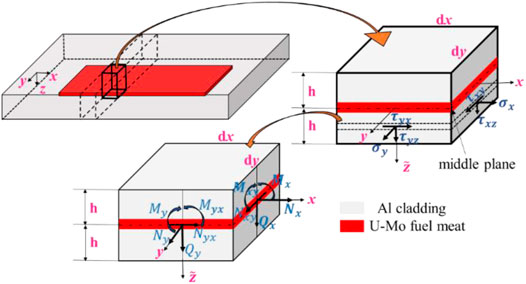
FIGURE A1. The schematic diagram of stress, per unit length of membrane forces and bending moments.
References
Baek, J. S., Cheng, L., and Diamond, D. (2015). Analysis of Local Scenarios in the NIST Research Reactor before and after Fuel Conversion.
Brown, N., Baek, J., Hanson, A., and Cheng, L. Y. (2013). Irradiation experiment Conceptual Design Parameters for NBSR Fuel Conversion. Brookhaven National Laboratory.
Brown, N. R., Hanson, A. L., and Diamond, D. J. (2013). Local Burn-Up Effects in the NBSR Fuel Element.
Burkes, D. E., Hartmann, T., Prabhakaran, R., and Jue, J. F. (2009). Microstructural Characteristics of DU-xMo Alloys with X=7-12 Wt%. J. Alloys Comp. 479, 140–147.
Cheng, L., Hanson, A., Diamond, D., Xu, J., Carew, J., and Rore, D. (2004). Safety Analysis Report (SAR) for License Renewal for the National institute of Standards and Technology Reactor. doi:10.2172/15007782
Cui, Y., Ding, S., Chen, Z., and Huo, Y. (2015). Modifications and Applications of the Mechanistic Gaseous Swelling Model for UMo Fuel. J. Nucl. Mater. 457, 157–164. doi:10.1016/j.jnucmat.2014.11.065
Deng, Y., Wu, Y., Zhang, D., Lu, Q., Tian, W., Qiu, S., et al. (2017). Thermal-mechanical Coupling Behavior Analysis on Metal-Matrix Dispersed Plate-type Fuel. Prog. Nucl. Energ. 95, 8–22. doi:10.1016/j.pnucene.2016.11.007
Dienst, W. (1977). Irradiation Induced Creep of Ceramic Nuclear Fuels. J. Nucl. Mater. 65, 1–8. doi:10.1016/0022-3115(77)90035-6
Ding, S., Huo, Y., and an Li, L. (2009). Effects of Fission Heat and Fuel Swelling on the thermal-mechanical Behaviors of Dispersion Fuel Elements. Mech. Adv. Mater. Structures 16, 552–559. doi:10.1080/15376490903133590
Ding, S., Huo, Y., and Yan, X. (2009). Modeling of the Heat Transfer Performance of Plate-type Dispersion Nuclear Fuel Elements. J. Nucl. Mater. 392, 498–504. doi:10.1016/j.jnucmat.2009.04.015
Fan, W., Peng, C., Chen, Y., and Guo, Y. (2016). A New CFD Modeling Method for Flow Blockage Accident Investigations. Nucl. Eng. Des. 303, 31–41. doi:10.1016/j.nucengdes.2016.04.006
Ghoshal, K., Kutty, T. R. G., Mishra, S., and Kumar, A. (2013). Creep Studies on U-7%Zr, U-7%Nb and U Rich U-Nb-Zr Alloys. J. Nucl. Mater. 432, 20–22.
Gong, X., Ding, S., Zhao, Y., Huo, Y., Zhang, L., and Li, Y. (2013). Effects of Irradiation Hardening and Creep on the Thermo-Mechanical Behaviors in Inert Matrix Fuel Elements. Mech. Mater. 65, 110–123. doi:10.1016/j.mechmat.2013.05.008
Gong, X., Zhao, Y., and Ding, S. (2014). A New Method to Simulate the Micro-thermo-mechanical Behaviors Evolution in Dispersion Nuclear Fuel Elements. Mech. Mater. 77, 14–27. doi:10.1016/j.mechmat.2014.06.004
Guo, Y., Wang, G., Qian, D., Hu, B., and Yu, H. (2018). Analysis of Flow Blockage of a Single Fuel Assembly in the JRR-3 20MW, 26th International Conference on Nuclear Engineering. doi:10.1115/icone26-81313
Hanson, A. L., and Diamond, D. (2011). Calculation of Design Parameters for an Equilibrium LEU Core in the NBSR. doi:10.2172/1030634
Hughes, T. J. R., and Liu, W. K. (1981). Nonlinear Finite Element Analysis of Shells: Part I. Three-Dimensional Shells. Comp. Methods Appl. Mech. Eng. 26, 331–362. doi:10.1016/0045-7825(81)90121-3
Iltis, X., Ben Saada, M., Mansour, H., Gey, N., Hazotte, A., and Maloufi, N. (2016). A New Characterization Approach for Studying Relationships between Microstructure and Creep Damage Mechanisms of Uranium Dioxide. J. Nucl. Mater. 474, 1–7. doi:10.1016/j.jnucmat.2016.02.027
Jian, X., Kong, X., and Ding, S. (2019a). A Mesoscale Stress Model for Irradiated U 10Mo Monolithic Fuels Based on Evolution of Volume Fraction/radius/internal Pressure of Bubbles. Nucl. Eng. Tech. 51, 1575–1588. doi:10.1016/j.net.2019.04.011
Kim, H.-J., Yim, J.-S., Lee, B.-H., Oh, J.-Y., and Tahk, Y.-W. (2014). Drop Impact Analysis of Plate-type Fuel Assembly in Research Reactor. Nucl. Eng. Tech. 46, 529–540. doi:10.5516/net.09.2013.103
Jian, X, Yan, F., Kong, X., and Ding, S. (2019b). Effects of U‐Mo Irradiation Creep Coefficient on the Mesoscale Mechanical Behavior in U‐Mo/Al Monolithic Fuel Plates. Nucl. Mater. Energ. 21, 100–706. doi:10.5516/net.09.2013.103
Kim, Y. S., Hofman, G. L., and Cheon, J. S. (2012). Mechanical Modeling of U-Mo Fuel Swelling in Monolithic Plates.
Kim, Y. S., Hofman, G. L., Cheon, J. S., Robinson, A. B., and Wachs, D. M. (2013). Fission Induced Swelling and Creep of U-Mo alloy Fuel. J. Nucl. Mater. 437, 37–46. doi:10.1016/j.jnucmat.2013.01.346
Kim, Y. S., and Hofman, G. L. (2011). Fission Product Induced Swelling of U-Mo alloy Fuel. J. Nucl. Mater. 419, 291–301. doi:10.1016/j.jnucmat.2011.08.018
Kong, X., Xu, T., Feng, Y., Shurong, D., Shenyang, H., and Douglas E, B. (2018). Thermo-mechanical Behavior Simulation Coupled with the Hydrostatic-pressure-dependent Grain-Scale Fission Gas Swelling Calculation for a Monolithic UMo Fuel Plate under Heterogeneous Neutron Irradiation. Open Eng. 8. doi:10.1515/eng-2018-0029
Ma, Z., Chen, R., Tian, M., Song, J., Zhang, D., Su, G. H., et al. (2018). Analysis of Flow Blockage Accidents in Rectangular Fuel Assembly Based on CFD Methodology. Ann. Nucl. Energ. 112, 71–83. doi:10.1016/j.anucene.2017.09.012
Mao, X., Jian, X., Wang, H., Zhang, J., Zhang, J., Yan, F., et al. (2021). Thermo-mechanical Coupling Behavior Analysis for a U-10Mo/Al Monolithic Fuel Assembly. Nucl. Eng. Tech. doi:10.1016/j.net.2021.03.003
Mei, Z., Liang, L., Kim, Y. S., et al. (2015). Grain Growth and Bubble Evolution in U-Mo alloy by Multiscale Simulations, International Meeting on RETER 2015-36th International Meeting on Reduced Enrichment for Research and Test Reactors. Seoul, South Korea.
Meng, Q., and Wang, Z. (2016). Creep Damage Models and Their Applications for Crack Growth Analysis in Pipes: A Review. Eng. Fracture Mech. 205, 547–576.
Meyer, M. K., Gan, J., Jue, J. F., Keiser, D. D., Perez, E., Robinson, A., et al. (2014). Irradiation Performance of U-Mo Monolithic Fuel. Nucl. Eng. Tech. 46, 169–182. doi:10.5516/net.07.2014.706
Miller, G. K., Burkes, D. E., and Wachs, D. M. (2010). Modeling thermal and Stress Behavior of the Fuel-Clad Interface in Monolithic Fuel Mini-Plates. Mater. Des. 31, 3234–3243. doi:10.1016/j.matdes.2010.02.016
Nayak, A. (2007). Elasto-plastic Analysis of Initially-Stressed Plates Using a 3D Degenerated Mindlin-Kirchhoff Shell Element, 48th AIAA/ASME/ASCE/AHS/ASC Structures, Structural Dynamics, and Materials Conference.
Newell, R., Park, Y., Mehta, A., Keiser, D., and Sohn, Y. (2017). Mechanical Properties Examined by Nanoindentation for Selected Phases Relevant to the Development of Monolithic Uranium-Molybdenum Metallic Fuels. J. Nucl. Mater. 487, 443–452. doi:10.1016/j.jnucmat.2017.02.018
Park, C. J., Lee, B., Alnajjar, A. T., Talafha, M. A., and Alkhatib, S. F. (2013). Depletion Analysis of Control Absorber in a Small Research Reactor. Ann. Nucl. Energ. 60, 377–382. doi:10.1016/j.anucene.2013.04.038
Perez, D. M., Lillo, M. A., Chang, G. S., Roth, G. A., Woolstenhulme, N. E., and Wachs, D. M. (2011). AFIP-1 Irradiation Summary Report.
Rest, J. (2010). Evolution of Fission-Gas-Bubble-Size Distribution in Recrystallized U-10Mo Nuclear Fuel. J. Nucl. Mater. 407, 55–58. doi:10.1016/j.jnucmat.2010.07.009
Robinson, A. B., Perez, D. M., Porter, D. L., Chang, G. L., Keiser, D. D., Wachs, D. M., et al. (2013). Irradiation Performance of U-Mo alloy Based Monolithic Plate-type Design Selection Update.
Robinson, A. B., Wachs, D. M., Burkes, D. E., and Keiser, D. D. (2008). US RERTR Fuel Development post Irradiation Examination Results.
Salvato, D., Leenaers, A., and Van den Berghe, S., and Detavernier, C. (2018). Pore Pressure Estimation in Irradiated UMo. J. Nucl. Mater. 510, 1–16. doi:10.1016/j.jnucmat.2018.08.039
Schulthess, J. L., Lloyd, W. R., Rabin, B., Wheeler, K., and Walters, T. W. (2019). Mechanical Properties of Irradiated U Mo alloy Fuel. J. Nucl. Mater. 515, 91–106. doi:10.1016/j.jnucmat.2018.12.025
Turkoglu, D. J., Wu, Z., Williams, R. E., and Newton, T. H. (2019). Neutronic Performance Characteristics of Different LEU Fuels in a Proposed NIST Research Reactor. Ann. Nucl. Energ. 128, 209–215. doi:10.1016/j.anucene.2019.01.006
Woolstenhulme, N. E., Glagolenko, I., Holdaway, K. K., and Rabin, B. H. (2015). Design of Irradiation Tests for Monolithic Fuel Qualification.
Woolstenhulme, N. E., Nielson, R. B., Wiest, J. D., Nielsen, J W., Roth, G A., and Snow, S D. (2012). DDE-MITR Status Report of Conceptual Design Activities.
Woolstenhulme, N. E., Nielson, R. B., Sprenger, M. H., and Housley, G. K. (2012). DDE-MURR Status Report of Conceptual Design Activities.
Wu, Z., Williams, R. E., Rowe, J. M., Newton, T. H., and O’Kelly, S. (2017). Neutronics and Safety Studies on a Research Reactor Concept for an Advanced Neutron Source. Nucl. Tech. 199, 67–82. doi:10.1080/00295450.2017.1335146
Yan, F., Jian, X., and Ding, S. (2019). Effects of UMo Irradiation Creep on the Thermo-Mechanical Behavior in Monolithic UMo/Al Fuel Plates. J. Nucl. Mater. 524, 209–217. doi:10.1016/j.jnucmat.2019.07.006
Yan, F., Zhao, Y., and Ding, S. (2017). Effect of Fuel Meat Thickness on the Non-uniform Irradiation-Induced Thermo-Mechanical Behavior in Monolithic UMo/Al Fuel Plates. Int. Conf. Nucl. Eng. doi:10.1115/icone25-67531
Zhao, Y., Ding, S., Huo, Y., Wang, C., and Yang, L. (2016). Irradiation-induced Thermomechanical Behavior in ADS Composite Fuel Pellets: Mechanism and Main Influencing Factors. J. Therm. stresses 39, 630–657. doi:10.1080/01495739.2016.1169117
Zhao, Y., Gong, X., Cui, Y., and Ding, S. (2016). Simulation of the Fission-Induced Swelling and Creep in the CERCER Fuel Pellets. Mater. Des. 89, 183–195. doi:10.1016/j.matdes.2015.09.135
Zhao, Y., Gong, X., Ding, S., and Huo, Y. (2014). A Numerical Method for Simulating the Non-homogeneous Irradiation Effects in Full-Sized Dispersion Nuclear Fuel Plates. Int. J. Mech. Sci. 81, 174–183. doi:10.1016/j.ijmecsci.2014.02.012
Keywords: U-Mo/Al monolithic fuel assembly, irradiation creep, thermo-mechanical behavior, irradiation swelling, fission gas bubbles, skeleton stress of porous fuel foil
Citation: Mao X, Jian X, Zhang J, Yan F, Ding S, Huo Y, Wang H, Zhang L and Li Y (2021) Effects of U-Mo Irradiation Creep Performance on the Thermo-Mechanical Coupling Behavior in U-Mo/Al Monolithic Fuel Assemblies. Front. Energy Res. 9:676881. doi: 10.3389/fenrg.2021.676881
Received: 06 March 2021; Accepted: 11 May 2021;
Published: 28 May 2021.
Edited by:
Wenzhong Zhou, Sun Yat-Sen University, ChinaReviewed by:
Rong Liu, South China University of Technology, ChinaZhang Chunyu, Sun Yat-Sen University, China
Copyright © 2021 Mao, Jian, Zhang, Yan, Ding, Huo, Wang, Zhang and Li. This is an open-access article distributed under the terms of the Creative Commons Attribution License (CC BY). The use, distribution or reproduction in other forums is permitted, provided the original author(s) and the copyright owner(s) are credited and that the original publication in this journal is cited, in accordance with accepted academic practice. No use, distribution or reproduction is permitted which does not comply with these terms.
*Correspondence: Shurong Ding, ZGluZ3NodXJvbmdAZnVkYW4uZWR1LmNu; Haoyu Wang, d2h5YWg2NjZAMTYzLmNvbQ==
†These authors share first authorship