 Renxiong Liu1
 Chaolong Zhang2*†
- 1School of Intelligent Engineering Technology, Jiangsu Vocational Institute of Commerce, Nanjing, China
- 2School of Electronic Engineering and Intelligent Manufacturing, Anqing Normal University, Anqing, China
An active balancing method based on the state of charge (SOC) and capacitance is presented in this article to solve the inconsistency problem of lithium-ion batteries in electric vehicles. The terminal voltage of each battery is collected first. Then, each battery SOC is accurately estimated by an extended Kalman filter (EKF) algorithm. In the experiment, the maximum absolute error of SOC evaluation is only 0.0061, and the mean absolute error is 0.0013 when the initial battery SOC is clear. Meanwhile, the maximum absolute error of SOC evaluation is 0.5 and the average absolute error of SOC is 0.0015 when the initial battery SOC is not clear. Afterward, an active balancing circuit based on the estimated battery SOC and capacitance is designed. The energy of capacitance is charged by the battery whose SOC is higher than the other batteries through the circuit to avoid the battery being overcharged. Then, the SOC of batteries gradually turn consistent. In the simulation experiment, the SOC difference of batteries is 7% before the balancing. Meanwhile, the SOC difference of batteries reduces to 0.02% after the balancing and the consuming time is merely 272s, which manifests that the proposed balancing method has a fast balancing speed and better balancing efficiency.
Introduction
Power system is one of the key components of electric vehicles, and it is usually composed of a large number of lithium-ion batteries in series and parallels (Yuan et al., 2015; Li et al., 2020). Owing to the differences in manufacturing processes and working conditions, voltage, capacity, internal resistance, self-discharge rate, and other parameters of batteries turn inconsistent gradually (Zhang et al., 2017; Zheng et al., 2018). With the elapse of battery cycle, the inconsistency of batteries increases dramatically, which increases the risk of runaway heat. Meanwhile, the battery balancing methods can effectively reduce the inconsistency (Baughman and Ferdowsi, 2008; Zhang et al., 2011; Gong and Tang, 2012; Phung et al., 2012; Hua et al., 2015; Lee et al., 2016; Morstyn et al., 2017; Ouyang et al., 2017; Shang et al., 2017; Wang et al., 2019; Moral et al., 2020).
According to circuit topology, battery balancing methods can be divided into passive balancing (Zhang et al., 2011; Hua et al., 2015) and active balancing methods (Baughman and Ferdowsi, 2008; Gong and Tang, 2012; Lee et al., 2016; Shang et al., 2017). The passive balancing method is an energy dissipation balancing. The excess power in the battery is converted into heat energy by energy dissipation elements to refine inconsistency of batteries. Resistance balancing is a typical passive balancing method (Zhang et al., 2011; Hua et al., 2015). The disadvantage of this balancing method is that it is impossible to replenish energy for low-capacity batteries. The active balancing method is an on-dispersive balancing method. Through different circuit topology and control strategy, energy transfers from battery to other batteries. Typical active balancing methods include transformer balancing method (Lee et al., 2016; Shang et al., 2017), inductance balancing method (Gong and Tang, 2012), capacitance balancing method (Baughman and Ferdowsi, 2008; Moral et al., 2020), and so on. However, it is difficult to develop topology with small size, easy integration, low cost, fast balancing speed, and high reliability for the balancing circuits. In recent years, the design of the active balancing circuit based on capacitance becomes feasible due to the emergence of various capacitances with large capacity and small volume. Meanwhile, it has advantages that include the following: the wasted energy is very low in the balancing process, the balancing process does not produce heat, and the balancing can be started in the case of charging, discharging, and preserving.
Based on the different control variables, the battery balancing methods can be divided into voltage balancing method (Phung et al., 2012; Wang et al., 2019) and state of charge (SOC) balancing method (Morstyn et al., 2017; Ouyang et al., 2017; Tang et al., 2020). The voltage balancing cannot represent the real state of electricity in each battery, so it cannot be promised in the application. Meanwhile, the SOC balancing method can overcome this shortcoming. The primary difficulty of applying SOC balancing is that the battery SOC cannot be measured directly, and it needs to be estimated. Therefore, the SOC estimation accuracy is critically related to the balancing effect.
Presently, the commonly used SOC estimation methods include open circuit voltage (OCV) method (Weng et al., 2014), current integration method (Okoshi et al., 2006), neural network (Yang et al., 2019), and Kalman filter algorithm (Kim and Cho, 2011; Xiong et al., 2012; Wang et al., 2018; Shrivastava et al., 2019). The OCV method needs to measure the battery OCV after the battery preserving for a long time and then estimate the corresponding SOC by searching the table. The current integration method can accurately estimate the battery SOC, but this method needs an accurate initial SOC value. Neural network needs a large number of historical test data to train and test the algorithm. The calculation of this method is very large and it is difficult to be applied in hardware with poor computing power. Extended Kalman filter (EKF) algorithm is an extended form of standard Kalman filter in the nonlinear case, and it is an efficient recursive filter. By using Taylor series expansion, the nonlinear system is linearized and then the signal is filtered by the Kalman filter framework, which shows excellent performance in battery SOC estimation (Kim and Cho, 2011; Xiong et al., 2012; Wang et al., 2018).
To prolong the cycle life of the batteries and protect their safety, an active balancing method based on SOC and capacitance is presented in this article. The terminal voltage of each battery is collected first, and then each battery SOC is estimated by using the EKF algorithm accurately. Afterward, an active balancing circuit based on the estimated SOC and capacitance is designed. During the working process of the balancing circuit, the energy of capacitance is charged by the battery whose SOC is higher than the other batteries to avoid the battery being overcharged. The balancing method improves the overall battery pack inconsistency fast and greatly in the experiment.
The rest of the article is arranged as follows. Battery Equivalent Circuit Model presents the battery equivalent circuit model. Extended Kalman Filter Algorithm Based Battery State of Charge Estimate Method illustrates the EKF algorithm–based battery SOC estimate method. Experiment Procedure and Results implements the experiment and gives the discussion. Finally, conclusion is drawn in Conclusion.
Battery Equivalent Circuit Model
The battery equivalent circuit models mainly include Rint model, Thevenin model, the second-order RC model, and the n-order RC model (Wang et al., 2020). In general, the model is more accurate when the number of RC increases. Meanwhile, the more model parameters need to be recognized and the corresponding amount of computation rises. In the work, the second-order RC model is selected, which is shown in Figure 1.
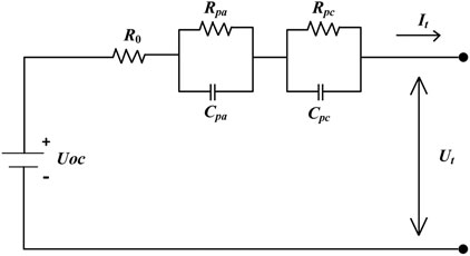
FIGURE 1. The second-order RC model.
The battery SOC defined by United States Advanced Battery Consortium (USABC) is the remaining battery capacity divided by the rated capacity under the same conditions of constant discharging current and constant temperature, which is as
where SOC(t) is the SOC at the time t; SOC(t0) is the SOC at the time t0; η = 1 is a Coulomb efficiency; I is the input current; Qn is the rated capacity of the battery. According to Kirchhoff’s law of the circuit, the second-order RC model can be expressed by Eqs 2–4 as
where
Extended Kalman Filter Algorithm–Based Battery State of Charge Estimate Method
The constructed battery model in Battery Equivalent Circuit Model reflects the relationship between the battery inputs, inner states, and battery outputs. The EKF algorithm estimates the battery system states after obtaining the battery model’s inputs and outputs for the battery in a typically dynamic nonlinear system (Kim and Cho, 2011; Xiong et al., 2012; Wang et al., 2018). A partly highlighted specific of the EKF algorithm is introduced.
First, the battery SOC is estimated by the Kalman observer through the following state space and measurement equations for the battery state model in the discrete time
where xk and yk are the state vector and the system output at step k, respectively; f and g are continuously differentiable nonlinear functions;
The nonlinear system is linearized by the EKF algorithm at every data point, which is as follows:
Mostly, the EKF algorithm can estimate the battery state space model accurately, as well as its parameters. The EKF algorithm based battery SOC estimation is reliable, high-precision, rapidly convergent, and robust even if starting values are erroneous. As a result, the EKF algorithm is adopted in the work to estimate the battery SOC for balancing strategy.
Experiment Procedure and Results
The Identification of Battery Equivalent Circuit Model Parameter
In the work, a hybrid pulse power characteristic (HPPC) test of the battery is performed to obtain the discharge data. 18650 lithium-ion battery with a rated capacity of 2.5 Ah is used in the experiment, and its detailed parameters are shown in Table 1. The HPPC test is conducted with 5 V 20 A NEWARE battery testing system (BTS 4000 type) and a calorstat at 25°C, which is shown in Figure 2.
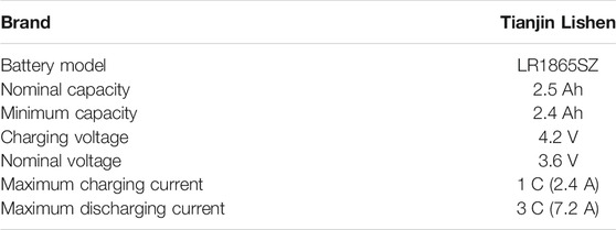
TABLE 1. Detailed parameters of the used 18650 battery.
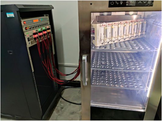
FIGURE 2. The HPPC test installations.
Figure 3 gives the HPPC test procedure. First, the 18650 battery is fully charged by using 0.5 C current, and the terminal voltage of the battery is 4.2 V. Then, the HPPC test is started. In the HPPC test process, the 18650 battery is discharged by using a 1 C current for 6 min at 25°C. Then, the battery is preserved for an hour, and the measured voltage variation curve of the 18650 battery in the 66 min is shown in Figure 4. The above process of discharging and preserving is repeated ten times. At last, the battery SOC is reduced to 0, and the battery voltage in the whole HPPC test process is shown in Figure 5.
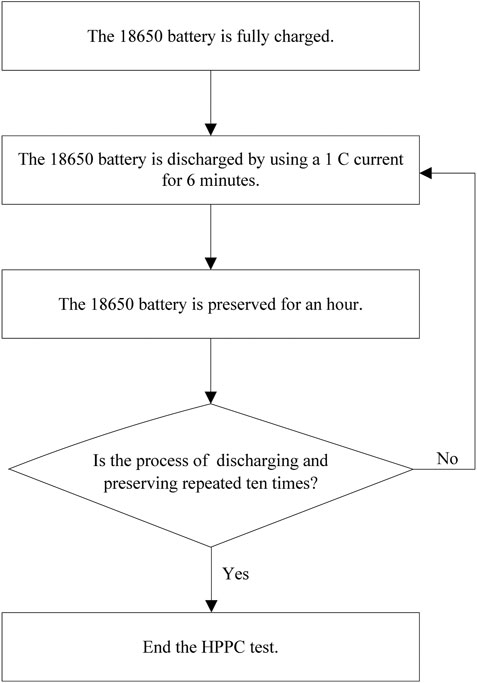
FIGURE 3. HPPC test procedure.
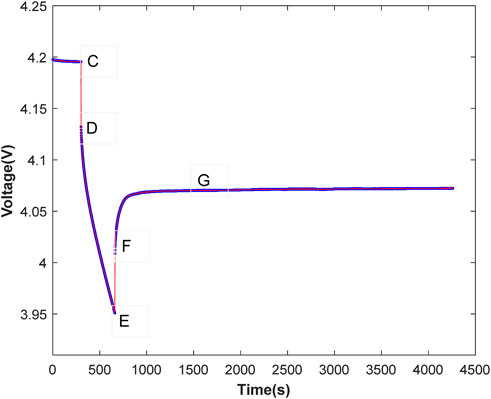
FIGURE 4. Battery discharge voltage curve in a pulse of HPPC test.

FIGURE 5. Battery discharge voltage curve in the HPPC test.
In Figure 4, time C is the starting time of discharging and time E is the end time of discharging. From the figure, it can be observed that the voltage drops at time C and increases at time E. Therefore, the voltage variation can be used to calculate the internal resistance R0 as
where UC, UD, UE, and UF represent the voltage of times C, D, E, and F, respectively.
The dynamic characteristics include polarization characteristics and concentration effects of battery. The time constant and initial voltages can be calculated as follows:
where U1(0) and U2(0) are the initial voltages of the two RC networks, respectively.
The variation of polarization and concentration voltage can be obtained by subtracting the terminal voltage that is preserved 15 min from the open circuit voltage at time F. The curve fitting tool was used to perform exponential fitting of polarization voltage according to
Referencing Eq. 13 and Eq. 14, the following parameters are generated:
The battery has been preserved for enough time before time D and the polarization and concentration effect can be regarded as 0. Referencing Eq. 11 and Eq. 12, the following equations can be obtained:
A very short variation from time E to time F can be regarded as 0, and the polarization and concentration voltage is unchanged. Eq. 16 and Eq. 17 are substituted as
Therefore, the model parameters can be obtained from the above equations, and recorded in Table 2.
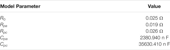
TABLE 2. Model parameters obtained in the HPPC test.
The measured battery discharge voltage curve in the HPPC test is shown in Figure 5. Meanwhile, the relationship of UOCV and SOC is obtained by using the curve fitting tool, which is shown in Figure 6 and its fitting polynomial is as
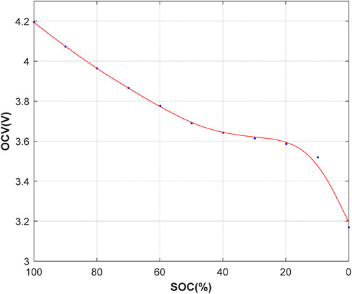
FIGURE 6. Fitting curve of OCV and SOC.
Battery State of Charge Estimation Experiment
After the second-order RC equivalent circuit model of each battery is established and the parameters are identified. Battery SOC estimation experiment based on the EKF algorithm is performed then. The estimation includes two tests. In test 1, the initial battery SOC is clear. Meanwhile, the initial battery SOC is not clear in test 2.
In test 1, the EKF algorithm is used to estimate battery SOC based on the voltage. Figure 7 shows the original battery SOC and the estimated battery SOC. Figure 8 shows the estimation error. In test 1, the maximum absolute error is 0.0061 and the mean absolute error is 0.0013.
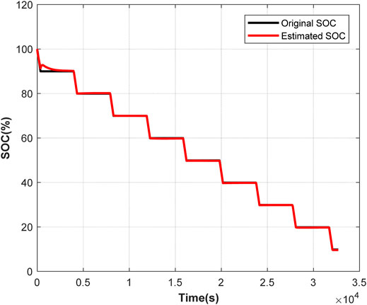
FIGURE 7. The original and estimated values of the battery SOC in test 1.
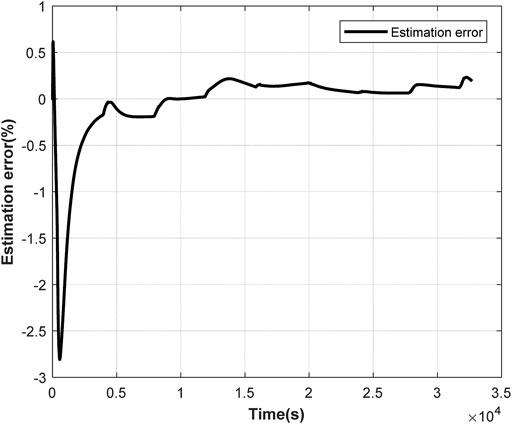
FIGURE 8. The estimation error in test 1.
In test 2, the initial battery SOC is unknown, and it is assumed to be 0.5. The estimated SOC value converges to the true value while the initial SOC differs greatly from the true value. Original battery SOC and estimated battery SOC are shown in Figure 9. The estimation error is shown in Figure 10. As shown in Figure 9 and Figure 10, the battery SOC estimated by the EKF algorithm has little error with the original battery SOC. In test 2, the maximum absolute error of SOC is 0.5 and the average absolute error of SOC is 0.0015.
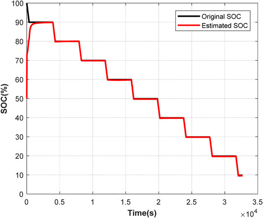
FIGURE 9. The original and estimated values of the battery SOC in test 2.
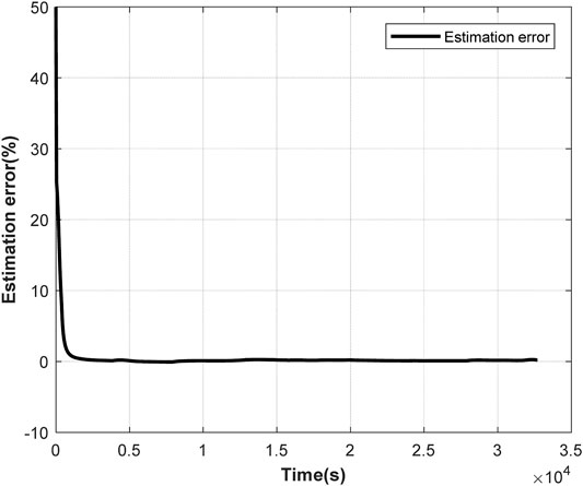
FIGURE 10. The estimation error in test 2.
From Figures 7–10, it can be concluded that the estimated SOC can rapidly converge to the original SOC even if the initial SOC value is uncertain, which indicates that the EKF algorithm has the advantages of high accuracy, fast convergence, and strong practicability in battery SOC estimation. The estimation method is applied to the balancing of batteries to improve the accuracy of estimating SOC.
The Simulation Design of Battery Pack Active Balancing Circuit
In the working process of batteries, its active balancing equivalent circuit based on the capacitance is shown in Figure 11. Pulse width modulation (PWM) signal controlling is carried out on switch tube S. Meanwhile, the battery B charges the supercapacitor E through the inductance L. First, the switching tube S is on. The battery B supplies power to the inductance L through circuit 1 to store energy, and i1 is the balancing current. Then the switch is off, the energy stored in the inductance L is released to the supercapacitor E through circuit 2. The supercapacitor E is charged by current i2. The balancing equivalent circuit is a chopper circuit, so the balancing current i1 can be controlled by adjusting the PWM wave duty radio of the switching tube S.

FIGURE 11. Charge balancing equivalent circuit.
The Simulink module is used to simulate the battery balancing circuit that is analyzed. Figure 12 shows the active balancing circuit in the work. Battery 1 to Battery 8 are eight batteries in series. The battery’s nominal voltage is set to 3.6 V and the rated capacity is set to 2.4 Ah. Rated capacity initial SOC of each battery is respectively set to 50%, 51%, 52%, 53%, 54%, 55%, 56%, and 57%. The batteries are charged by a 2.4 A current with 5 kHz switching frequency and 20% duty ratio.
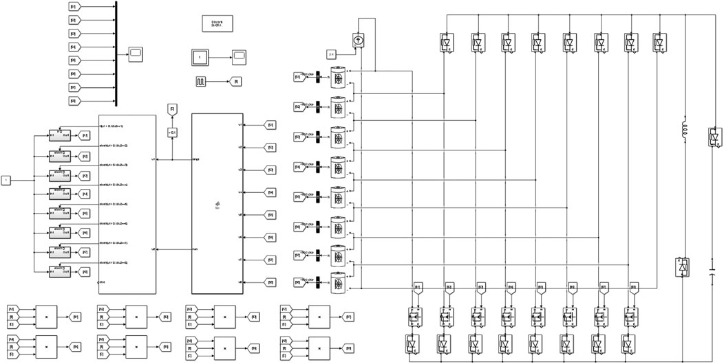
FIGURE 12. Active balancing simulation circuit.
The procedure of the active balancing method is shown in Figure 13, and the balancing control method adopts the extreme difference method. When the deviation of maximum SOC and minimum SOC of batteries is greater than 0.02, the balancing circuit is working. Otherwise, the balancing circuit is out of work. The program is written in the Matlab-Function module, and each battery SOC is the input of the module. When the battery is charged, the module outputs the difference between the maximum and minimum SOC of batteries, as well as the number of the battery with the maximum SOC. The output of the Matlab-Function module is used as the input of the IF-Action module in the Simulink, and it controls the balancing circuit by setting the judgment conditions.
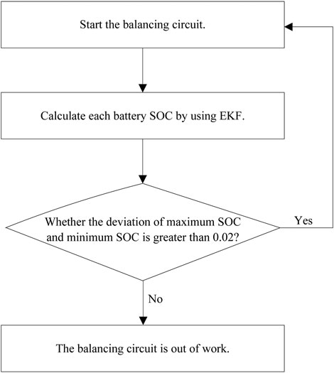
FIGURE 13. Active balancing procedure.
Figure 14 shows the SOC variations of eight batteries. When the time is 272s, all battery SOCs turn consistent, and the balancing process is completed. The inductance current variation is shown in Figure 15. In the figure, the balancing current reduces to 0 as the time is 272s.
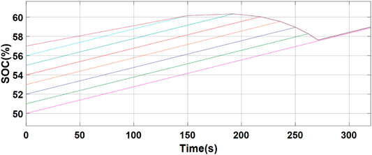
FIGURE 14. SOC variations of eight batteries.
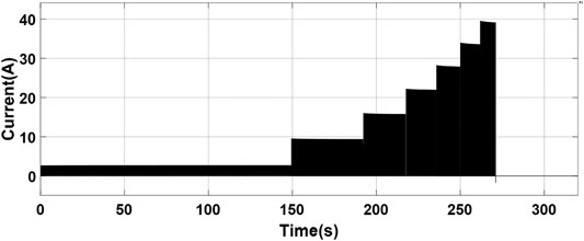
FIGURE 15. Inductance current variation.
Seven-phase steady-state inductor current of charge balancing is shown in Figure 16, which is a clear presentation of Figure 15.
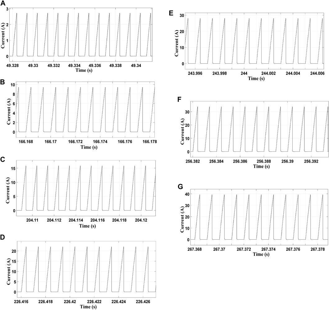
FIGURE 16. Seven-phase steady-state inductor current of charge balancing.
After the batteries are charged, the inconsistency of the batteries is improved. The SOC difference of batteries is 7% before charging. After balancing, the SOC difference of batteries drops to 0.02%. Meanwhile, the balancing time is merely 272s.
Therefore, this balancing scheme not only improves the inconsistency of the batteries but also increases the performance of the batteries. The balancing circuit current is controllable, and the balancing method is effective.
Conclusion
An active balancing method based on SOC and capacitance has been presented to solve the inconsistency problem of lithium-ion batteries in the battery packs of electric vehicles. The battery SOC has been estimated by the EKF algorithm accurately. The maximum absolute error of SOC evaluation is 0.0061, and the mean absolute error is 0.0013 when the initial battery SOC is clear. Meanwhile, the maximum absolute error of SOC evaluation is 0.5 and the average absolute error of SOC is 0.0015 when the initial battery SOC is not clear. An active balancing circuit based on the estimated battery SOC and capacitance balancing has been designed, and the balancing procedure only costs 272s, which is controllable and effective.
Data Availability Statement
The raw data supporting the conclusions of this article will be made available by the authors, without undue reservation.
Author Contributions
RL wrote the manuscript. CZ implemented the experiment.
Funding
This work was supported by the National Natural Science Foundation of China (51607004), the Natural Science Research Key Project of Education Department of Anhui Province (KJ2020A0509), the Anhui Provincial Natural Science Foundation (2008085MF197), and the Collaborative Innovation Project of Anhui Universities (GXXT-2019-002).
Conflict of Interest
The authors declare that the research was conducted in the absence of any commercial or financial relationships that could be construed as a potential conflict of interest.
Publisher’s Note
All claims expressed in this article are solely those of the authors and do not necessarily represent those of their affiliated organizations, or those of the publisher, the editors and the reviewers. Any product that may be evaluated in this article, or claim that may be made by its manufacturer, is not guaranteed or endorsed by the publisher.
References
Baughman, A. C., and Ferdowsi, M. (2008). Double-Tiered Switched-Capacitor Battery Charge Equalization Technique. IEEE Trans. Ind. Electron. 55 (6), 2277–2285. doi:10.1109/tie.2008.918401
Gong, Y., and Tang, T. (2012). “Controlling and Balancing of Lithium Battery Voltage Based on Inductance Equilibrium Method,” in International Symposium on Power Electronics Power Electronics, Electrical Drives, Automation and Motion, Sorrento, Italy, June 20–22, 2012 (IEEE), 347–352.
Hua, Y., Cordoba-Arenas, A., Warner, N., and Rizzoni, G. (2015). A Multi Time-Scale State-Of-Charge and State-Of-Health Estimation Framework Using Nonlinear Predictive Filter for Lithium-Ion Battery Pack with Passive Balance Control. J. Power Sourc. 280, 293–312. doi:10.1016/j.jpowsour.2015.01.112
Kim, J., and Cho, B. H. (2011). State-of-Charge Estimation and State-Of-Health Prediction of a Li-Ion Degraded Battery Based on an EKF Combined with a Per-Unit System. IEEE Trans. Veh. Technol. 60 (9), 4249–4260. doi:10.1109/tvt.2011.2168987
Lee, K. M., Lee, S. W., Choi, Y. G., and Kang, B. (2016). Active Balancing of Li-Ion Battery Cells Using Transformer as Energy Carrier. IEEE Trans. Ind. Electron. 64 (2), 1251–1257. doi:10.1109/TIE.2016.2611481
Li, J., Ku, Y., Liu, C., and Zhou, Y. (2020). Dual Credit Policy: Promoting New Energy Vehicles with Battery Recycling in a Competitive Environment? J. Clean. Prod. 243, 118456. doi:10.1016/j.jclepro.2019.118456
Moral, C. G., Laborda, D. F., Alonso, L. S., Guerrero, J. M., Fernandez, D., Rivas Pereda, C., et al. (2020). Battery Internal Resistance Estimation Using a Battery Balancing System Based on Switched Capacitors. IEEE Trans. Ind. Applicat. 56 (5), 5363–5374. doi:10.1109/tia.2020.3005382
Morstyn, T., Savkin, A. V., Hredzak, B., and Agelidis, V. G. (2017). Multi-agent Sliding Mode Control for State of Charge Balancing between Battery Energy Storage Systems Distributed in a DC Microgrid. IEEE Trans. smart grid 9 (5), 4735–4743. doi:10.1109/TSG.2017.2668767
Okoshi, T., Yamada, K., Hirasawa, T., and Emori, A. (2006). Battery Condition Monitoring (BCM) Technologies about lead-acid Batteries. J. Power Sourc. 158 (2), 874–878. doi:10.1016/j.jpowsour.2005.11.008
Ouyang, Q., Chen, J., Zheng, J., and Hong, Y. (2017). SOC Estimation-Based Quasi-Sliding Mode Control for Cell Balancing in Lithium-Ion Battery Packs. IEEE Trans. Ind. Electron. 65 (4), 3427–3436. doi:10.1109/TIE.2017.2750629
Phung, T. H., Crebier, J. C., and Lembeye, Y. (2012). “Voltage Balancing Converter Network for Series-Connected Battery Stack,” in IECON 2012-38th Annual Conference on IEEE Industrial Electronics Society, Sorrento, Italy, June 20–22, 2012 (IEEE), 3007–3013.
Shang, Y., Xia, B., Zhang, C., Cui, N., Yang, J., and Mi, C. (2017). A Modularization Method for Battery Equalizers Using Multiwinding Transformers. IEEE Trans. Veh. Technol. 66 (10), 8710–8722. doi:10.1109/tvt.2017.2702065
Shrivastava, P., Soon, T. K., Idris, M. Y. I. B., and Mekhilef, S. (2019). Overview of Model-Based Online State-Of-Charge Estimation Using Kalman Filter Family for Lithium-Ion Batteries. Renew. Sustain. Energ. Rev. 113, 109233. doi:10.1016/j.rser.2019.06.040
Tang, X., Zou, C., Wik, T., Yao, K., Xia, Y., Wang, Y., et al. (2020). Run-to-Run Control for Active Balancing of Lithium Iron Phosphate Battery Packs. IEEE Trans. Power Electron. 35 (2), 1499–1512. doi:10.1109/tpel.2019.2919709
Wang, Y., Tian, J., Sun, Z., Wang, L., Xu, R., Li, M., et al. (2020). A Comprehensive Review of Battery Modeling and State Estimation Approaches for Advanced Battery Management Systems. Renew. Sustain. Energ. Rev. 131, 110015. doi:10.1016/j.rser.2020.110015
Wang, Y., Zhang, X., Liu, C., Pan, R., and Chen, Z. (2018). Multi-Timescale Power and Energy Assessment of Lithium-Ion Battery and Supercapacitor Hybrid System Using Extended Kalman Filter. J. Power Sourc. 389, 93–105. doi:10.1016/j.jpowsour.2018.04.012
Wang, Z., Lin, H., and Ma, Y. (2019). Improved Capacitor Voltage Balancing Control for Multimode Operation of Modular Multilevel Converter with Integrated Battery Energy Storage System. IET Power Electron. 12 (11), 2751–2760. doi:10.1049/iet-pel.2019.0033
Weng, C., Sun, J., and Peng, H. (2014). A Unified Open-Circuit-Voltage Model of Lithium-Ion Batteries for State-Of-Charge Estimation and State-Of-Health Monitoring. J. Power Sourc. 258, 228–237. doi:10.1016/j.jpowsour.2014.02.026
Xiong, R., He, H., Sun, F., and Zhao, K. (2012). Evaluation on State of Charge Estimation of Batteries with Adaptive Extended Kalman Filter by experiment Approach. IEEE Trans. Vehicular Technol. 62 (1), 108–117. doi:10.1109/TVT.2012.2222684
Yang, F., Li, W., Li, C., and Miao, Q. (2019). State-of-Charge Estimation of Lithium-Ion Batteries Based on Gated Recurrent Neural Network. Energy 175, 66–75. doi:10.1016/j.energy.2019.03.059
Yuan, X., Liu, X., and Zuo, J. (2015). The Development of New Energy Vehicles for a Sustainable Future: A Review. Renew. Sustain. Energ. Rev. 42, 298–305. doi:10.1016/j.rser.2014.10.016
Zhang, C., Jiang, Y., Jiang, J., Cheng, G., Diao, W., and Zhang, W. (2017). Study on Battery Pack Consistency Evolutions and Equilibrium Diagnosis for Serial- Connected Lithium-Ion Batteries. Appl. Energ. 207, 510–519. doi:10.1016/j.apenergy.2017.05.176
Zhang, X., Liu, P., and Wang, D. (2011). The Design and Implementation of Smart Battery Management System Balance Technology. J. Convergence Inf. Technol. 6 (5), 108–116. doi:10.4156/jcit.vol6.issue5.12
Keywords: lithium-ion batteries, active balancing, SOC, EKF algorithm, capacitance
Citation: Liu R and Zhang C (2021) An Active Balancing Method Based on SOC and Capacitance for Lithium-Ion Batteries in Electric Vehicles. Front. Energy Res. 9:773838. doi: 10.3389/fenrg.2021.773838
Received: 10 September 2021; Accepted: 30 September 2021;
Published: 04 November 2021.
Edited by:
Yujie Wang, University of Science and Technology of China, ChinaReviewed by:
Jiaqiang Tian, Xi’an University of Technology, ChinaJi Wu, Hefei University of Technology, China
Xiao Wang, Wuhan University, China
Copyright © 2021 Liu and Zhang. This is an open-access article distributed under the terms of the Creative Commons Attribution License (CC BY). The use, distribution or reproduction in other forums is permitted, provided the original author(s) and the copyright owner(s) are credited and that the original publication in this journal is cited, in accordance with accepted academic practice. No use, distribution or reproduction is permitted which does not comply with these terms.
*Correspondence: Chaolong Zhang, emhhbmdjaGFvbG9uZ0AxMjYuY29t
†ORCID: Chaolong Zhang, orcid.org/0000-0003-3892-5124