 Jingyu Guo1
 Huansheng Lai
 Wenzhong Zhou
- 1Sino-French Institute of Nuclear Engineering and Technology, Sun Yat-Sen University, Zhuhai, China
- 2Department of Mechanical Engineering, City University of Hong Kong, Hong Kong, China
- 3School of Physics and Electronic Engineering, Linyi University, Linyi, China
Reactor structural integrity and nuclear safety are seriously affected by the fission gas behaviors and relevant physical phenomena in nuclear fuels. In this review, the fission gas behavior and relevant phenomena in different fuels for both models and experiments have been comprehensively overviewed, including fission gas release, gap/plenum pressure, grain growth, swelling, fission gas diffusion coefficients, and fuel cladding mechanical and chemical interactions under irradiations. The fission gas behaviors can be classified into single fission gas behavior and combined fission gas behavior with more interacting physics together. In addition, fission gas behaviors are also profoundly influenced by fuel performance, which is different in different kinds of fuels. The data of different nuclear fuels are collected, for example, UO2, MOX, metallic, U3Si2, UN, UC, and TRISO fuels. The models and experiments on fission gas behaviors are summarized into figures and tables for better comparisons. The fission gas behaviors are mainly subjected to burnup, time, and temperature, which profoundly impact these behaviors. The burnup will motivate the fission gas release and other fission gas behaviors. With the fuel temperature increase, the extent of some fission gas behaviors will be more strengthened, including fission gas release, gap/plenum pressure, grain growth, swelling, and fuel cladding mechanical and chemical interactions. The predicted data are consistent with the measured data, and the modeling results generally agree well with the experimental data. In addition, the observation of enhanced gas release at high burnups is unexpected. However, the modeling approaches on fission gas release behaviors still have certain uncertainties. Therefore, it still has considerable space to be improved and is worth studying in future work.
Introduction
Nuclear fuels are the most critical materials in different types of reactors. UO2 fuels have been successfully and broadly used as primary fuels in commercial light-water reactors. However, the other types of fuels are also used or proposed for different reactors, including the MOX (mixed oxide), metallic, U3Si2, UN, UC, and TRISO (TRi-structural ISOtropic particle fuel) fuels. The design and safety of nuclear power plants are based on nuclear fuels. Hence, the fuel performance is vital for a reactor. In order to improve fuel performance, researchers have made considerable efforts. This review mainly focuses on fission gas behaviors in different fuels. However, the other phenomena closely relevant to fission gas behavior will also be discussed, including gap/plenum pressure, grain growth, swelling, fission gas diffusion coefficient, and fuel cladding mechanical and chemical interactions.
The integrity and safety of nuclear fuels are significantly crucial for fuel development progress in both normal and accidental conditions (Burkes et al., 2015). The theories and experiments on the fission gas behaviors have been investigated through early research reactors (Kim et al., 1996). The development of advanced fuel design with substantially improved performance has been acknowledged by the international community under severe accidents since the Fukushima accident in 2011 (Cappia et al., 2019). Thus, the U.S. Department of Energy’s Nuclear Energy Office (DOE-NE) launched the Accident Tolerant Fuel Campaign (ATF Campaign). The improvement of fuel, plant operation, and safety has to be achieved by implementing innovative fuel systems during design basis and exceeding the design basis accidental conditions (Barani et al., 2019). The design of fuel rods adopts the predicted fission gases in the fuel rods of exceeding lifetime, which is well used in the current reactor designs. However, the vital issue is the inability of current fuel designs suitable for the over-expected gas release and the enlarged burnup range in extending the lifetime of existing reactors (Rest et al., 2019).
The performance of nuclear fuel rods is heavily affected by the behavior of the gaseous fission products under the irradiation condition (Barani et al., 2020). The fission gases are released to the rod’s free volume, increasing the rod’s inner pressure or creating bubbles, resulting in the fuel swelling. Therefore, the pellet–cladding mechanical interaction is enhanced. The mechanical behavior of the fuel rod is affected by the above processes. In addition, the thermal conductance of the fuel cladding gap is reduced by the fission gas release, and the fuel thermal conductivity is degraded by gases within bubbles, which makes the temperature distribution in the fuel pellets to be influenced (Barani et al., 2017). The thermal mechanistic of the fuel rods is significantly affected by the fission gases. The fuel will swell when the fission gases get into the bubbles, closing the fuel cladding gap and having mechanical interaction with the fuel cladding. The pressure of the fuel rod free volume and the degradation of the thermal conductivity of the rod filling gas are caused by the fission gas release (Liu et al., 2016).
Fuel performance codes are used to study the safety of nuclear reactors and final fuel repositories. The prediction of fission gas release is significant in any nuclear fuel performance code. The FGR (fission gas release) is often divided into two steps in fuel performance codes. First, the fission gases are produced by fission reactions according to the linear power rating, and the parts of gases diffuse to the grain boundaries. The thermal diffusion is dominant at high temperatures. The fission gas diffusion is driven by the irradiation-enhanced defect concentrations, except for thermally activated defects, even if the athermal part is vital at low temperatures. The fuels of fast neutron factors are extremely affected by the athermal diffusion due to their high thermal conductivity, such as nitride fuels, where the release is probably lower than that of the oxide fuels at high temperatures, but the gap conductance is still degraded. Second, the gases on the grain boundaries are released and stored relying on their concentration and release threshold relevant to temperature or temperature gradient, and other properties (Barani et al., 2017).
Fuel performance codes are also used to model the fission gas behavior as an important part of the thermal–mechanical analysis of nuclear fuel rods. The fission gases are released to the rod’s free volume, increasing the rod’s inner pressure or creating bubbles, resulting in the fuel swelling. Therefore, the pellet–cladding mechanical interaction is enhanced. The mechanical behavior of the fuel rod is affected by the above processes. In addition, the thermal conductance of the fuel cladding gap is reduced by the fission gas release, and the fuel thermal conductivity is degraded by gases within bubbles, which influences the temperature distribution in the fuel pellets. The treatment of various interactive phenomena is acquired in modeling the fission gas behavior in nuclear fuels under irradiation. The generated gases within the fuel grains diffuse to the grain boundaries, and then the fuel swelling is induced by bubbles precipitating and growing at the grain faces. The thermal FGR is caused by the release of the final gas from the grain faces, which takes place after bubble growth and interlink, and is promoted by gas atom and vacancy diffusing to the bubbles. In addition to the above diffusion processes, experiments indicate that gases from the grain boundaries are probably released by micro-cracking through the mechanism of grain face separation, which causes the high FGR under the transient conditions, is described as fast kinetics, and is understood as a diffusion-controlled process. So, the fast FGR in transient conditions is usually regarded as a burst release. The fission gas release rate increases by micro-cracking along grain boundaries under irradiation experiments because the accumulation of fission gas causes thermal stresses. Planar separations are observed on the grain surfaces after transient heating. The gases contained in the grain surfaces are released by cracking along a given grain–grain contact in experiments. The loss of gases stored in the micro-cracking and released from cracked grain faces result in an additional gas release from the grain boundaries under the transient condition (Paraschiv et al., 1997).
Single Fission Gas Behavior
The fuel pellets are fabricated with many small grains. Fission gases are induced by fission reactions that diffuse to the grain boundaries, which probably form intergranular bubbles or resolve into the grain matrix. The intergranular bubbles will grow at grain faces or edges when more fission gases are collected. The growing bubbles will coalesce with an adjacent bubble to become interlinked bubbles. Ultimately, fission gases will be released to the free space via the interlinkage (Kim et al., 1996). The amount of xenon and krypton is more than that of any other fission gases. Hence, the study of fission gases is mainly in terms of these two gases. The fission gases diffuse from the matrix to the grain boundaries and into the existing pores, and then give away from the fuel cladding gap and plenum when the interconnected channel between the nucleate inter and intragranular bubbles is built up. The fuel pellet is subjected to the thermal–mechanical interaction of the fuel and is the first barrier of fission gases to the environment. The center temperature is evaluated by the degradation of the thermal conductivity of the gap since the fission gases diffuse from the fuel pellet to the gap, and the inner pressure on the cladding will increase with the continuing release of fission gases. The enhanced gas release at high burnups is unexpected and worth attention, which occupies a considerable part (Hales et al., 2016).
In this section, we first review the work on the single fission gas behavior of the UO2 fuel. Since there is much research on this, we will summarize some results and have some discussions. Following that, we will review the single fission gas behavior of some other fuels, mainly including the MOX, metallic, U3Si2, UN, UC, and defective fuels. After the discussions about the fuels other than the UO2 fuel, some comparisons among different fuels will be presented on the single fission gas behavior. Some critical research projects and outputs will be summarized and compared.
UO2 Fuels
Matzke (1980) reviewed gas release mechanisms in UO2 and performed parametric studies with existing codes, filling the gaps in experimental data and further theoretical work on gas atom sites and mobilities, which will help to achieve sound physically based gas release codes with reliable input data to obtain acceptable predictions for normal and off-normal operating conditions.
Forsberg and Massih (1985a) studied the fission gas release under time-varying conditions. The numerical method for solving the diffusion coefficient, source term with time dependence and the concentration of gas atoms from grains is derived.
van Uffelen et al. (2002) studied the developed fission gas release mechanistic model in LWRs (light-water reactors). This model not only largely improves the underlying basic mechanisms of the fission gas release but also combines the kinetics of inside and outside granular behaviors of the gas atoms. When the empirical Halden criterion was simulated with a burnup surpassing the related 1% release, its prediction only had minor errors. The fission gas release model is relatively accurate, and the prediction of the incubation period with burnup under stationary conditions is very precise. Furthermore, it predicts the concentration of the grain boundaries where it is filled with 2 × 10¹⁵ atoms/cm2, which is close to the other literature’s data. It showed some essential parameters for the modification of the FGR model, and the release threshold is not affected by the average grain size. It will affect the release rate after the interlinkage of grain boundary bubbles occurs. The simulation of the FUMEX cases was acceptable since it did not underpredict release kinetics during the ramp. The main results from the simulation of the FUMEX cases are summarized in Table 1.

TABLE 1. Main results from the simulation of the simplified FUMEX case (van Uffelen et al., 2002).
Lӧsӧnen (2002) studied a fission gas release and diffusion model by irradiating intragranular bubbles in LWR UO2 fuel, observing the fission gas behavior, and modeling the intragranular bubbles at a high pressure, whose results agree well with the latest experiments. A special treatment was applied when significant bubble coarsening temperature was elevated, and the coarsening was modeled at a specific burnup temperature. The model showed a better-predicted performance of the bubbles. Example prognostications demonstrated that a detailed model could predict the experiments well compared with a simple one.
Kim (2004) conducted a theoretical analysis of the fission gas release, including two points, grain boundary and lattice, using some math formulations to simulate, whose results show that when the relative diffusive ratio is close to or greater than grain radius, the whole fission gas release progress must be affected by the grain boundary. The fission gas release will increase at high burnups.
The short-time closed solution of the fission gas concentration and the definition of the fractional release yield the fission gas release fraction:
In the post-irradiation examination (PIE) case,
Kim et al. (2008) derived a two-step two-stage model, coming up with a burnup factor, setting the threshold value as 25,000 MWd/MTU. The results indicate that FRAPCON-3 code corresponds well with the measurements compared with ANS (American Nuclear Society) 5.4, modified ANS 5.4, and Forsberg-Massih models when the entire burnup ranges up to 75,000 MWd/MTU.
The two-step, two-stage model is as below:
where
Viswanathan et al. (2009) studied the fuel pins of the PHWR (pressurized heavy-water reactor) bundle discharged after the burnup of 7,528 MWd/tU. The results showed that the fission gas release from the outer ring of the fuel was about 8%, and that from the interior and central pin was below 1%. Thus, it indicated that the fission gas release was affected by the gases of grain boundary sweeping in the outer fuel pin.
The result of the fission gas release in fuel pins of fuel bundle No. 54505 is shown in Table 2, and the comparison of predicted and measured FGRs and internal pressures is also summarized in Supplementary Table S1 (Viswanathan et al., 2009).
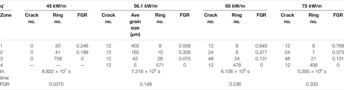
TABLE 2. Calculated fractional gas release for various linear heat generation conditions (Kim et al., 1996).
The model developed by Koo et al. (2010) is based on the ANN (artificial neural network) method, using CABRI (a research reactor used to simulate a power transient in France) and NSRR (nuclear safety research reactor in Japan) data, to predict the fission gas release during the RIA (reactivity-initiated accident) events of typical LWRs. The fission gas release into the pellet-cladding gap under fuel failure conditions, which occurs at the high enthalpy in RIA. The fuel will be fracked or melted in this situation. The difference between the measured and calculated RIA FGRs is presented in Supplementary Table S2 (Koo et al., 2010).
Tonks et al. (2018) found that the fuel performance is affected by the production and release of fission gases in the UO2 fuel, which leads to swelling and increase of gap pressure. The majority of the FGR undergo three stages: in the first stage, gas atoms are produced, and they migrate from the bulk; in the second stage, grain face bubbles nucleate, grow, and interconnect until they attach to grain boundaries; in the third stage, gases transport through interconnected grain boundary channels until they arrive at a free surface and are released. These mechanisms are mainly based on gas atom diffusion, though some gas release is a result of knockout, recoil, and burst release.
Koo et al. (2019) studied the FGR at a constant linear power of 30 kW/m and a burnup of 60 MWd/kgU irradiating the ceramic and the metallic micro-cell pellets during typical working situations. FGR in the ceramic micro-cell pellet is close to and even below that in the UO2 pellet at up to 10 times high diffusion, which results from its large grain size and wall-collision on gas diffusion. In addition, the FGR in ceramic micro-cell pellet is also assessed for the doped UO2 pellet, ∼2% at 60 MWd/kgU. However, the FGR in the metallic micro-cell pellet is lower than that in the UO2 pellet because of its lower fuel temperature and the presence of walls. In working conditions, both the fraction of perfect walls and the magnitude of gas diffusion determine the degree of reduction in the FGR in the micro-cell pellets. It will more clearly reveal the impact of walls on gas atoms’ behavior and release in the micro-cell pellets if the PIE results become available for the pellets irradiated in the Halden reactor.
Prudil et al. (2020) simulated the FGR of intragranular diffusion, providing the Included Phase Model (IPM) with the local source term for each grain. The results show that the fission gas release timing is contributed by microstructural variation. The FGR is calculated as a function of burnup using Eq. (4):
Verdolin et al. (2020) modeled the fission gas behavior in fast reactor fuel with BISON, and the FGR is affected by many phenomena, applying local simulations to find some critical limitations. It indicates that BISON has a marked improvement in the FGR predictions. The performed sensitivity analysis highlights the strong dependency of the FGR on the grain size. It concluded that an improved representation of the fission gas behavior under fast reactor conditions is provided by extending the fission gas behavior model.
Wu et al. (2018) studied inverse UQ (uncertainty quantification) through kriging meta-models in the INL (Idaho National Laboratory)’s fuel performance code BISON (A Finite Element-Based Nuclear Fuel Performance Code) FGR model using the Risϕ-AN3 FGR time-series measurement data, which is projected onto the PC subspace as “transformed experiment data.” The shape of the BISON FGR simulation is different from the measurement data. Thus, the original data have convergence problems for the MCMC (Markov Chain Monte Carlo) samples. The results indicate that the correspondence of BISON simulation and Risϕ-AN3 FGR time-series measurement data can be significantly improved. The limitation of BISON is the burst release of fission gases accumulated at the grain boundaries during a sudden power drop. Its phenomena are complex because physics is insufficient. The confidence in FGR predictions can be improved when the BISON applies different fuel design or irradiation conditions. Incorporating this work’s data available is regarded as a demonstration of the methodology and new experimental data.
Matsson et al. (2007) studied a significant database on the BWR fuel of different designs from several reactor units by non-destructive determinations of the FGR in the irradiated fuel rods. With an average burnup of well above 60 MWd/kgU, the fuel rods’ measurement results show that more modern fuel designs in reducing FGR are comparable to older designs in decreasing the impact of control blade movements.
Barry (2021) studied the DME-176, BDL-422, and DME-221 fuels, and the PIE results of their irradiation experiments proved again the fuel microstructure effect on the FGR in the thoria fuel. Lower density fuel with large granules surrounded by porous regions results in higher FGR. Higher density and more uniform fuel result in superior FGR in thoria fuels with a similar irradiation history. New techniques, resulting in the fuel with uniform grain size and density, can decrease the FGR, even in CANDU (Canada Deuterium Uranium, a Canadian pressurized heavy-water reactor) UO2 fuel.
Rest et al. (2019) summarized the existing literature on the fundamental mechanisms of the FGR under normal working conditions. It is found that the irradiation-induced re-crystallization in the UO2 fuel at high burnups can cause the microstructure variation and would affect the fuel behavior, resulting in fission gas release increase.
Kim et al. (1996) studied the interlinkage fraction of intergranular bubbles with restructuring and cracking effects in the fuel using a 2D hexagonal model based on the percolation theory. The results showed that the model coupled with the FASTGRASS (Fast Gas Release and Swelling Subroutine, A Mechanistic Model for the Prediction of Fission Gas Release) predicts the FGR comparable with the experimental data from AECL (Atomic Energy of Canada Limited)-2,230, CBX test. The FGR can be significantly enhanced by restructuring and cracking, with the number of radial cracks increasing remarkably in the region. The maximum fractional volume swelling of the interested range has a positive influence on the FGR. The result of the fractional gas release for various linear heat generation conditions is shown in Table 2. The measured FGR is compared with various simulation results from the AECL-2230 test fuel in Supplementary Table S3 (Kim et al., 1996).
Che et al. (2021), using statistical calibration with in-reactor experimental data, improved the BISON FGR model for chromium/aluminum-doped UO2 fuel and analyzed the computing cost and efficiency of Bayesian, variational Bayesian Monte Carlo (VBMC), kriging, principal component analysis (PCA), and Markov Chain Monte Carlo (MCMC). The result demonstrates that VBMC combines with the kriging meta-model to describe the inference of Bayesian.
Bernard et al. (2002) studied an efficient FGR analysis model in the UO2 and MOX fuels using the Framatome ANP and COPERNIC, used thermal model, and described its qualification when the FGR severely relies on temperature. A slight temperature uncertainty may yield a rather considerable uncertainty on the gas release fraction, as diffusion is the major FGR mechanism, and the activation energies of the diffusion coefficient are high. The Framatome ANP model is designed for industrial application, simple, efficient, fast, and robust. The model has a vast database that involves many phenomena for the FGR behavior.
The fission gas release vs. burnup in UO2 fuel is summarized in Figures 1A–F. Most modeling results tend to increase, few have a decreasing tendency, and a dramatically increasing curve indicates that the fission gas release is extremely sensitive to burnup. Some results show a slow rise, demonstrating that burnup has little effect on the fission gas release in those cases. The fission gas release varies with time in the UO2 fuel. Some fission gas releases quickly increase, while others slowly increase with time, as shown in Figures 1G—J.
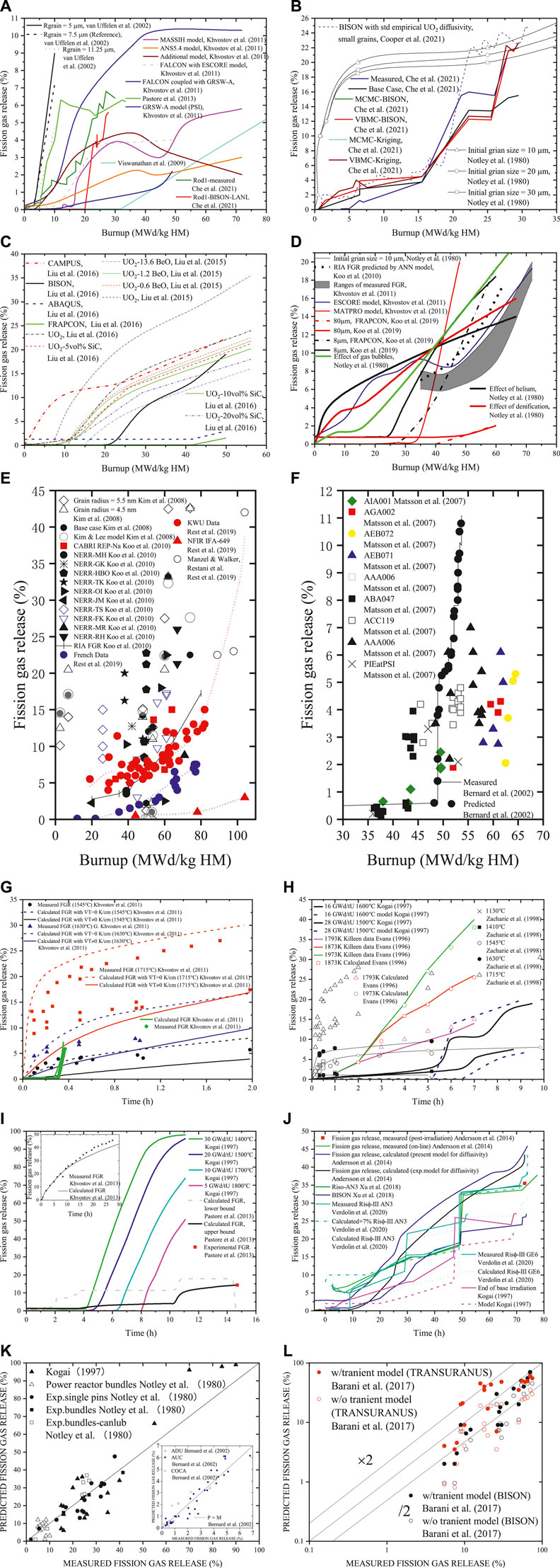
FIGURE 1. (A–F) Fission gas release vs. burnup in the UO2 fuel (Notley et al., 1980; Kogai, 1997; Bernard et al., 2002; van Uffelen et al., 2002; Matsson et al., 2007; Kim et al., 2008; Viswanathan et al., 2009; Koo et al., 2010; Koo et al., 2010, 2019; Khvostov et al., 2011; Pastore et al., 2013; Liu et al., 2015; Liu et al., 2016; Rest et al., 2019; Che et al., 2021; Cooper et al., 2021). (G–J) Fission gas release vs. time in the UO2 fuel (Evans, 1996; Kogai, 1997; Zacharie et al., 1998; Khvostov et al., 2011; Pastore et al., 2013; Andersson et al., 2014; Wu et al., 2018; Verdolin et al., 2020). (K,L) The predicted fission gas releases to the measured ones in the UO2 fuel (Notley et al., 1980; Kogai, 1997; Bernard et al., 2002; Barani et al., 2020).
The predicted fission gas releases vs. the measured ones are presented in Figure 1K. The model predictions were obtained by both BISON and TRANSURANUS for the UO2 fuel, and the relative error was computed as (FGRcalculated-FGRmeasured)/FGRmeasured, and the result is shown in Figure 1L.
MOX Fuels
Sato et al. (2011) studied helium and other fission gases in the irradiated fuel in JOYO up to ∼50 MWdkg−1 when the pin puncture and heating tests are used to measure the average burnup of the pin. The comparison of the calculated results with experimental data shows that the puncture result of Xe is consistent with the heating test, and it well demonstrates the experimental method’s feasibility. The helium gas release begins at lower than 1173 K under the isothermal situations. The release rate of helium is higher than that of other fission gases under irradiation conditions due to their different mobility in the fuel. The fission gas diffusion coefficient agrees well with the data in the literature, and the experimental data are close to the calculated results at the top of the fuel pins. The amounts of estimated generated, retained, and release gases in fuel pellets are shown in Table 3. The amount of retained and generated gas in the Q476 pin was determined using different processes. The fission gas release was estimated by the pin puncture test. The MOX fuel pin was filled with fission gases under irradiation. Fission gases were transformed from the irradiated pin to a chamber, and then were measured there. The chamber was in a closed manner, and the gas volume was calculated by Boyle–Charles’ law using the measured gas pressure. The constitution of the fission gases was analyzed by a gas chromatograph. Nitrogen gas of 0.1 MPa was introduced into the free volume of the pin, and it was analyzed by Boyle–Charles’ law to evaluate the volume.

TABLE 3. Amount of generated, retained and released gases (Sato et al., 2011).
Colle et al. (2013) studied fission product release and varied microstructures in the irradiated MOX fuel at a burnup of 44.5 GWd/tHM at high temperatures by KEMS (Knudsen effusion mass spectrometry) and SEM (scanning electron microscope) measurements. Three temperature stages of FGR were observed by the KEMS: the first stage is the face release or discharge from open grain boundaries, the second stage is diffusion and intergranular release, and the third stage is matrix vaporization resulting in intergranular bubbles release. The fuel pellet in the central zone retains less gas than the outer zone, significantly affecting the FGR in a pile because the irradiation temperature is too much higher. Using the KEMS measurements to simulate the transient temperature indicates that 80% of the gas is venting at higher temperatures in higher irradiation areas but not the central zone.
Prudil et al. (2019) studied fission gas accommodation and venting in the MOX fuel using a two-species phase model. Simulations are conducted and analyzed to explore the impact of stochastic grain heterogeneity on macroscopic FGR and swelling. The results show that FGR timing is attributed to microstructural variation, and simulating the increasing distance of an open surface indicates that the generation of isolated regions results in uneven macroscopic properties and FGR not being able to vent. The fractional coverage is related to the grain boundary concentration and vacancy fraction before venting.
Koo et al. (2002) modeled the effect of inhomogeneity on the FGR in the MOX fuel and found that the number density, size distribution, and fraction of Pu retained in the Pu-rich particles all affect gas release in the MOX fuel. Fixing the median size and the fraction of Pu contained in the Pu-rich particles, the smaller particle size dispersion makes more gas release. The model can predict the FGR in the MOX fuel by comparing it with the measured data in the two OCOM (optimized CO-milling) MOX fuels.
The amount of gas release:
Ishida et al. (1994) evaluated the heterogeneity influence of Pu content on the FGR in the MOX fuels by a practical and straightforward method. The model used the diffusion theory for homogeneous UO2 fuels and distribution of local Pu content in the designed MOX fuels to simulate the FGR based on various parameters. The results show a synergistic effect of fission-rate-enhanced diffusion of fission gas atoms, and the local fission rate peaking at the fission fragment range in the fuel matrix leads to increasing FGR in the MOX fuels due to the Pu heterogeneity. FGR enhancement is more significant in the MOX fuels of lower average Pu fraction under a given average power density, and is more apparent at lower operating temperatures as long as the temperature is high enough to cause the FGR. So, the parameters in the PuO2 particle model have to be carefully selected to avoid overprediction.
The fission gas release fraction (FGRF) of a fuel rod with homogeneous UO2 fuels:
Metallic Fuels
Fission gases are released from the fuel pellet under irradiation when the cladding defect exists, including manufacturing, material defects, and/or operational anomalies, to form a path for fission gases to escape. Thus, understanding the fission gas released from the fuel is essential to evaluate a set of accidents and develop reasonable safety margins under the predicted conditions (Lee et al., 2001).
The fission gas mainly consists of xenon and krypton in the fuel matrix due to their absolute insolubility. The gases will be excluded from the fuel if their kinetics are sufficient and do not get into the gap/plenum or cluster in tiny bubbles of the fuel, whose density is lower than that of its solid fuels, the volume of the gas atoms within bubbles is bigger than the volume of the replaced fissile atoms, or fission-product atoms transformed into solid phases. Fission gases released from the fuel participate in any volume, making the free volume within the fuel pin connected. These connected gas regions consist of the fuel/cladding gap and the porosity related to the gap, which means open porosity (Karahan et al., 2009).
King et al. (2011) compared the optimization of grain boundary from their modeling data with bulk diffusion data using temperature, diffusion time, and grain size, providing that grain boundary diffusion in metallic fuels is similar to that in other fuels; short time release experiments determine lattice diffusion coefficients, and long-time release extracts the tripe product to design the experiments. The temperature dependence of the measured diffusion can deduce active energies.
Hwang et al. (2000) studied the improved FGR model and rod deformation on metallic fuel in the LMR by comparing MACSIS (Metal fuel performance Analysis (computer) Code for Simulating the In-reactor behavior under Steady-state conditions) MOD1 that is the sub-model of MACSIS to analyze the metallic fuel design in KALIMER with other codes. MACSIS MOD1 predicted well the FGR in both the trend and the absolute magnitude with the ANL experimental data. MACSIS MOD1 FGR predicted the experiments better than MACSIS. The prediction of diametric strains is the same for both, while MACSIS MOD1 predicted temperature well with LIFE-M compared with the above three models’ predictions. The MACSIS MOD1 is regarded as a standard for the predictions of the experimental data and analyses of the metallic fuel rod performance.
Burkes et al. (2015) studied the FGR of the irradiated U-Mo monolithic fuel by heating post-irradiated samples. The experiments indicated that the FGR is related to release mechanisms, observing three FGR stages at the range of 30–1,000°C: the first is the precipitation of fission gas products from the solid solution, coalescence into large pores, and final diffusion via the uncovered edges of the samples; the second is heating the system to cause the U-Mo fuel swelling greatly and fracking, which is the most critical FGR behavior; and the third is the final FGR behavior observed as the sample exceeding two-thirds of the alloy melting temperature. The comparison of the results with available literature data shows that the release behavior corresponds well with the U–Mo alloy measurements.
Yun et al. (2013) studied the FGR in the irradiated U–Pu–Zr metallic fuel through a mechanistic kinetic rate theory approach. The irradiated U–Pu–Zr fuel forms a unique microstructural feature of three-phase regions. It separately addresses the interpreted fission gas behavior in each of these phases’ regions because of the strong dependence of fission gas bubble kinetics on the microstructure. The densely distributed laminar porosity structure causes most of the released fission gas in the α-U region. The fission gas bubble size distribution in the central and γ-U regions was measured through SEM micrographs. Materials properties and model parameters for the two regions were determined by comparing the experimental data with simulated bubble size distribution. Significant uncertainties exist for many materials properties of the U–Pu–Zr fuel. So, parametric sensitivity of several materials properties and model parameters must be performed on the microstructure of fission gas bubbles.
U3Si2 Fuels
Barani et al. (2019) studied the fission gas behavior in the U3Si2 fuel of an LWR by adopting a multiscale approach to lower-length scale model fission gaseous intragranular and grain-boundary behavior. The model explained the variation of fission gas bubbles, intragranular gas atoms diffusion, and FGR. The intragranular single gas atom diffusion coefficient was obtained using the DFT (density function theory) calculations. The FGR and swelling behaviors as well as the various important model parameters’ assessments were represented. Sensitivity analysis indicates that the uncertainties of parameters exist in the model, such as the grain-boundary vacancy diffusion coefficient related to weak Pearson and sensitive coefficients exceeding the expected temperature range. In this model, an operational multiscale modeling approach for fission gas behavior in U3Si2 was built; a promising potential modeling framework was provided for the calculation of FGR and swelling in the U3Si2 and engineering-scale fuel analysis in LWR, indicating that future research on the characterization of the parameters can be addressed by using a sensitivity analysis. The model can be improved as new data are available from theoretical and experimental investigations. For instance, the BISON fuel performance code of Idaho National Laboratory has used this model.
Miao et al. (2018) studied the fission gas behavior of the U3Si2 under LOCA (loss of coolant accident) conditions in an LWR by the rate theory model, based on BISON simulation to last for hours without re-flooding. The result has shown that the fission gas behavior is favorable when fuel temperature can be restricted below 1200 K during LOCA. On the contrary, the potential formation of nanocrystalline HBS and rapid grain growth at the boundary may cause significant fission gas release and serious gaseous swelling.
UN Fuels
Vaidyanathan et al. (1993) found a correlating expression for the FGR in the developed UN fuel, revealing some physical mechanisms. The release fraction at low burnups and low temperatures increases with burnup. However, a saturation release fraction at intermediate and high burnups results from effective gas retention inside the fuel matrix by intragranular bubbles at higher temperatures.
Storms (1988) found that diffusion causes nitrogen loss from the fuel through the barrier and the reaction with cladding or coolant when the UN is heated in a high-temperature reactor. When sufficient fission product metals are formed, the reaction produces a liquid between fission product metals and the uranium in UN, and adequate nitrogen is lost from the fuel. The diffusion rate was improved by the liquid through grain boundaries and weakened the contact intergrains via forming cracks. The diffusion rate increase inside grains for all components is expected with the nitrogen content decrease in the UN. The release can be accelerated by any process in early life and will be magnified, and will scatter the data with the unsure temperature. The stoichiometry reduction of the UN will increase the coalescence of gas bubbles to raise the release rate in later life. Thomas et al.'s expression seems to underpredict the release in conditions to result in a significant release. The Bars expression appears to overpredict the release. All the expressions mentioned noble gas release but the Cs release.
Ross data are
Baars data are
Thomas data are
Besmann et al. (2014) studied the fission product release and survival in the UN-kernel LWR TRISO fuels, including fuel kernels and TRISO coating layers, at the optimized fuel loading and burnup. The FGR leads to pressure buildup in the particles, and we must analyze their survival ability since they will bear the pressure. The pellet geometries varying with densities limit the available information of the FGR from UN. Fission recoil release depends on recoil ranges based on fission fragment energies and diffusive release from the UN kernels into the buffer region through extrapolating higher temperature release from the irradiated high-density UN fuel pellets. The width of the buffer-IPyC gap is probably affected by the high swelling rates, causing extra mechanical stress on the IPyC between the kernel and buffer. Gases must occupy high fractions in the total release, and the total vapor pressures have to exceed the condensed fission product phases. Fractional release from the UN kernel of noble gases and amount of Xe based on kernel diameter is shown in Supplementary Table S4 (Besmann et al., 2014).
UC Fuels
Hy et al. (2012) studied the capability of fission product release at 1,200 and 1,550°C by synthesizing five different UC pellets, which have various features in density, porosity, and composition. The measured γ spectrometry determined the release properties of thirteen elements. The highest released fraction was in the OXA sample at 1,550°C; COMP30 and PARNNe also exhibit interesting releases except at low and high values of atomic number, and the OXA sample release at 1,200°C is the worst and is better at 1,550°C.
Defective Fuels
The fuel-bundle defect rate is important for fuel performance in the defective fuel, even resulting in fuel failures, such as power ramp defects, fabrication defects, and fretting defects. These defects have been reduced to low levels in fuel fabrication, fuel design, and reactor operation.
Lewis et al. (2017) summarized fission product release theory in defective fuels. It concludes that thermal and athermal diffusion induces fission product release from the fuel matrix in defective fuel elements. Knockout is an inefficient release mechanism at lower fuel temperatures, and the efficiency of a surface fission fragment to stop within the thin fuel-to-sheath gap is less than a bit of percent. Diffusive release at intermediate fuel temperatures is contributed by enhanced vacancy production with fuel oxidation. A Booth-diffusion-type model can be used to model the release from the fuel matrix and empirical diffusion coefficient. Low-temperature recoil progress makes fission product release from uranium contaminate the heat transport system when the size of the fuel debris is close to the range of the fission fragment.
Barry et al. (2019) studied fission product release in the defective fuel by the experiments that state that the defected thoria as well as the defected UO2 ones operates at a high power. The results show that thoria causes a lower fission product burden in the PHTS (primary heat transport system) than urania during the steady state. Thoria cannot use the defective fuel fission product transport models developed for urania.
Comparisons of Single Fission Gas Behavior Among Different Fuels
Millett et al. (2012) studied the FGR in the oxide fuel by grain boundary percolation modeling, which combined the developed 2-stage Booth model with network percolation algorithms to investigate the influence of the variation of grain boundary saturation rates on the FGR. The results indicate that the FGR can be reduced by the percolation of the grain boundary network. A fully 3D fuel performance code should take the current coupling percolation algorithms into account for the FGR.
Claisse et al. (2015) studied the athermal FGR in oxide fuels by the TRANSURANUS (a fuel performance code) code to model and simulate the IAEA (International Atomic Energy Agency) FUMEX (Fuel Modelling Exercise) project: two rod types from the SUPERFACT irradiation experiment (irradiation tests for oxide fuels containing minor actinides in PHENIX fast reactor in France) and two rods irradiated in the JOYO reactor (a test sodium-cooled fast reactor in Japan and JOYO was a historical country name in Japan); and to test the developed model with large open porosity in the oxide fuels during various conditions. When thermally activated diffusion dominates, predicting release through a physical description of open porosity rather than purely empirical contributions can lead to similar results, and when only athermal release is activated, it can lead to significantly different results. So, this is encouraging, especially since no special fitting is required to predict the release. Other important parameters of fission gas release (such as lattice diffusion coefficient) should also be carefully considered because they have significant uncertainty and may have a correspondingly strong effect on the predicted release of fuel performance codes. Fission gas release of the FUMEX project of the IAEA and for the two types of rods considered in the SUPERFACT irradiation experiment is summarized in Table 4.
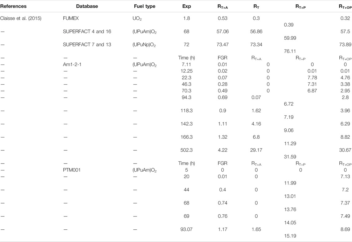
TABLE 4. Fission gas released (%) in the FUMEX project of the IAEA, the SUPERFACT irradiation experiment, the JOYO irradiation, and the FUMEX project of the fuel rod Am1-2-1 (Claisse et al., 2015).
Sensitivity investigation was performed for four configurations, where the empirical athermal release is regarded as a fixed percentage (RT) or diffusion as a low-temperature term of the diffusion coefficient (RT+A), at which the empirical athermal release module is substituted by the new model considering the porosity (RT+P) and the open porosity (RT+OP).
Fuel and irradiation properties of the first case of the FUMEX project of the IAEA, the SUPERFACT irradiation experiment, and the JOYO irradiation are shown in Table 4. The first type is an LWR rod of the first FUMEX project of the IAEA. The minor-actinide-containing FBR fuels are concerned in the second type: two fuel rods irradiated with high porosity for a short time in the JOYO reactor and two cases irradiated with low porosity in the SUPERFACT irradiation experiment. The FGRs of the FUMEX project for the fuel rod Am1-2-1 and PTM001 are summarized in Table 4. The athermal release at the beginning of the irradiation, with the temperature rising and keeping high for a long time, becomes not essential.
Barani et al. (2017) studied the transient FGR in the oxide fuel that incorporated the burst release combined with fuel micro-cracking by the BISON and TRANSURANUS codes, simulating 19 LWR fuel rod irradiation experiments from the OECD/NEA (Organisation for Economic Co-operation and Development/Nuclear Energy Agency) IFPE (International Fuel Performance Experiments) database and comparing code predictions with the available experimental data. The results demonstrated that using the transient model, compared with the canonical models, can improve all the FGR descriptions, including the predictions of integral FGR at the end of the irradiation. The FGR kinetics represents more consistency in both codes by comparing the variation of the calculated FGR time and online measurements of the Risϕ-3 AN3 and AN4 experiments, which differs from the simulation of the canonical model and can reproduce the burst effect using the transient model. We can predict diametric xenon concentration in both codes by comparing the calculations of PIE for the Risϕ-3 AN3 experiment, and the transient model can have improved results of local xenon concentration compared with the canonical models. It was concluded that simulating fuel rods with the transient FGB model permits both an improved kinetics of FGR during transients and precision of FGR predictions. The model results in two codes, indicating that the description of physics, but the pure diffusion-based model could adapt the transient fission gas behavior model. Micro-cracking captures extra and relevant physics of transient FGB relative to the pure diffusion-based models, and the burst release can be well predicted by the valid transient FGB model. The irradiation experiments from the OECD/NEA IFPE database are summarized in Table 5.
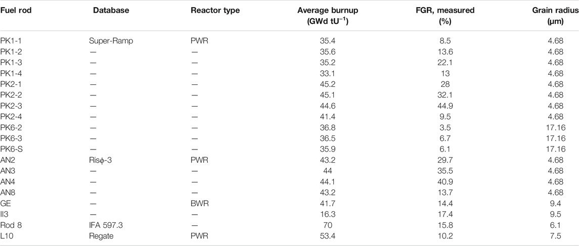
TABLE 5. Summary of irradiation experiments from the OECD/NEA IFPE database analyzed in Barani’s work (Barani et al., 2017).
The fission gas release vs. burnup in the MOX fuel is summarized in Figures 2A–D. Most fission gas release will increase with burnup. However, a maximum value exists for a few fission gas releases, and some FGRs have fluctuations. The fission gas release vs. burnup in the MOX, U3Si2, and UO2 fuel is summarized in Figures 2E–H. Figures 2E,G show that fission gas release increases with burnup in the MOX fuels, Figure 2F shows some fission gas release first reach their maximum and then drop with burnup, while the others increase slowly; Figure 2H shows some fission gas release dramatically increase at low burnups, and some FGRs either increase slowly or have fluctuations in the UO2 fuel.

FIGURE 2. (A–D) Fission gas release with burnup in the MOX fuel (Ishida et al., 1994; Koo et al., 2002; Prudil et al., 2019). (E–H) Fission gas release with burnup in the MOX, U3Si2 and UO2 fuels (Ishida et al., 1994; Fisher et al., 2002; Lӧsӧnen, 2002; Denis et al., 2003; Kim et al., 2004; Prudil et al., 2020; Yingling et al., 2021). (I–L) Fission gas release with burnup in the metallic and UO2 fuels (Hwang et al., 2000; Lee et al., 2001; Karahan et al., 2009; Rest, 2012; Verdolin et al., 2020). (M–P) Fission gas release with burnup in the UO2, UN, UC and TRISO fuels (Prajoto et al., 1978; Storms, 1988; Vaidyanathan et al., 1993; Koo et al., 2000; Zhang et al., 2020). (Q–T) Fission gas release with time in the UO2 and metallic fuels (White et al., 1983; Bernard et al., 2002; Koo et al., 2002; King et al., 2011; Pastore et al., 2013; Barani et al., 2020; Che et al., 2021). (U–X) Fission gas release with time in the UC, U3Si2, MOX, metallic and UO2 fuels (Prajoto et al., 1978; Sato et al., 2011; Millett et al., 2012; Winter et al., 2017; Miao et al., 2018; Barani et al., 2019). (Y,Z) Fission gas release with temperature in the MOX, metallic, and UN fuels (Storms, 1988; Sato et al., 2011; Colle et al., 2013; Burkes et al., 2015).
The fission gas release with burnup percentage in the metallic and UO2 fuels is summarized in Figures 2I–L. The fission gas release greatly increases at low burnups and then reaches a relatively stable level in the metallic fuel (as shown in Figures 2I–K). Fission gas release increases with burnup in the UO2 fuel (as shown in Figure 2L). The fission gas release with burnup percentage in the UO2, UN, UC, and TRISO fuels is summarized in Figures 2M–P. Figure 2M shows the fission gas release increases with burnup in the UO2 fuel, Figure 2N shows that most fission gas release results are in an increasing tendency, and only few results are in a decreasing tendency in the UN fuel; Figure 2O and the embedded figure of Figure 2M show that fission gas release increases with burnup in the UC fuel, Figure 2P shows that fission gas release increases with burnup in the TRISO fuel.
Fission gas release with time in the UO2 and metallic fuels is summarized in Figures 2Q–T. Some fission gas release quickly increase, while the others slowly increase with time in UO2 (as shown in Figures 2Q, S, T). Figure 2R and the embedded figure of Figure 2T show the fission gas release increases with time in the metallic fuels. Fission gas release with time in the UC, U3Si2, MOX, and UO2 fuels is summarized in Figures 2U–X. Figure 2U shows fission gas release increases with time in the UC fuel. Figures 2V,W show fission gas release increases with time in the U3Si2 fuel. The bar in the embedded figure of Figure 2V shows that the fission gas release elevates with time in the MOX fuel. Figure 2X shows fission gas release increases with time in the UO2 fuel.
Fission gas release increasing with temperature in the MOX, metallic, and UN fuels is summarized in Figures 2Y, Z. Figure 2Y shows fission gas release increases with temperature in the metallic fuels, and the embedded figure of Figure 2Y shows fission gas release increases with temperature in the MOX fuel. Figure 2Z shows fission gas release elevation with temperature in the UN fuel.
Gap/Plenum Pressure
The gap/plenum pressure is related to many parameters, for example, moles of gas, ideal gas constant, volume of capacity, and gas temperature inside the cladding. The release of fission gas increases with the amount of gas in the cavity on the basis of the original amount of gas (Hales et al., 2016).
Jeong et al. (2015) studied the UO2 fuel mixed with boron, considering the boron’s stability when fuel sinters and being able to be used as an integral burnable absorber, using fuel performance code FRAPCON-UNI. The result shows that increased gap pressure makes the GB gas release difficult by lifting the saturated limitation, and the gas release is retarded after about five GWD/MTU. Due to their high diffusivities, the helium and nitrogen releases are merely affected by the various resolution parameters. The rod internal pressure with burnup at the end of life is summarized in Supplementary Table S5 (Jeong et al., 2015).
The gap/plenum pressure basically increases with burnup in the UO2, metallic, and U3Si2 fuels. However, the pressure may drop within certain burnup ranges in the UO2 and U3Si2 fuels (as shown in Figures 3A,B).
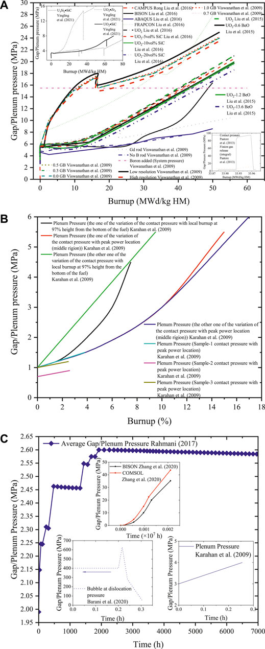
FIGURE 3. (A) Gap/plenum pressure with burnup in the U3Si2 and UO2 fuels (Viswanathan et al., 2009; Pastore et al., 2013; Liu et al., 2015; Liu et al., 2016; Yingling et al., 2021). (B) Gap/plenum pressure with burnup in the metallic fuel (Karahan et al., 2009). (C) Gap/plenum pressure with time in the TRISO, metallic, and UO2 fuels (Karahan et al., 2009; Rahmani, 2017; Barani et al., 2020; Zhang et al., 2020).
The gap/plenum pressure increases with time in the metallic and TRISO fuels, as shown in Figure 3C. However, the pressure of UO2 may elevate rapidly first and then gradually drop with time. One UO2 case shows no pressure change at first, then the pressure increases suddenly, and after reaching its maximum, it decreases with time in the embedded figure in Figure 3C.
Grain Growth
The grain growth is improved by the doped fuel when the fuel is fabricated. The fuel strength is reduced by large grains to increase the margins of the fuel–cladding interaction, the increased fission gas retention is anticipated, and the intragranular diffusion length is increased to capture the physics-based FGR and gaseous swelling in the BISON. The effective fission gas diffusivity is enhanced by large grain. The density functional theory (DFT) is used to study the fission gas behavior in atomic scales, such as calculating the enthalpy combined with empirical potential entropy calculations to accurately predict the intrinsic Xe diffusion. The modified Kröger-Vink notation points out that Xe accommodation does not specify a site. However, within the vacancy cluster, large clusters of U and O vacancies contain the Xe atoms in a set of DFT data, and low migration barriers are exhibited by many large clusters, whose concentrations have little contribution to D1 diffusion. The role of defect production on D2 diffusion is considered by using DFT data for the system’s free energy in a developed cluster dynamics model (Cooper et al., 2021).
The grain growth mainly has three effects on the FGR. First, the solution of the fission gas is low. So, the gas in the newly formed crystal does not deposit again in the move grain boundary but is accumulated at the grain faces. Second, the grain growth increases the diffusion distance of the fission gas atoms generated in the grains. However, it does not reduce the release rate. Third, grain growth makes the capacity of the grain boundaries stored fission gas decrease (Hales et al., 2016).
The fission gas behavior in nuclear fuels is related to the evolution of the material of the chemistry and microstructure. The fuel chemistry causes the diffusion of gas atoms and irradiation-produced defects—grain growth with time and temperature under irradiation and fuel chemistry like stoichiometry. Fission products and gas bubbles impede grain growth as the grain boundaries move. The fission gas release can be predicted accurately when all related processes are considered. Fuel materials undergo irradiation-induced recrystallization, where the as-fabricated micro-size poly-crystalline grains are varied into sub-micro-sized grains at relatively high doses, on a different level, below temperatures in which annealing defect takes place. Fission gases diffuse from the inner grain to the grain boundaries, varying the materials corresponding with gas-induced swelling from intragranular to intergranular. In addition, gas-bubble/precipitate complexes as pinning sites make the potential recrystallization nucleation immobilized and influence the dose at the beginning of the recrystallization. In order to model the phenomena closer to reality, the combination of these factors should be taken into consideration (Rest, 2012).
The grain growth behavior is summarized in Figure 4. The grain size varies with temperature in the metallic fuel (Figure 4A). The grain size increases with time in the U3Si2 fuel (Figure 4B). The predicted fuel radius to the measured fuel radius in UO2 fuel is presented (Figure 4C). The calculated grain growth to the measured grain growth in UO2 fuel is shown (Figure 4D).
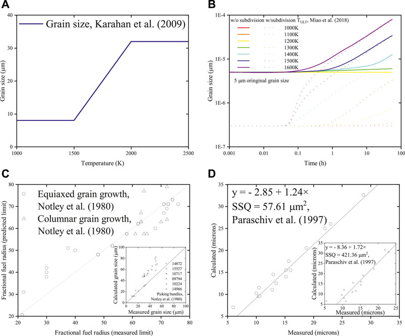
FIGURE 4. (A) Grain size with temperature in the metallic fuel. (B) Grain size with time in U3Si2. (C) Predicted fuel radius to fractional fuel radius in UO2. (D) Calculated vs. measured swelling in UO2 (Notley et al., 1980; Paraschiv et al., 1997; Karahan et al., 2009; Miao et al., 2018).
Swelling
The fission gases in the fuel grains are previously created by their low solubility and then probably form bubbles. The evaluation of intragranular bubbles is controlled by gas atoms, which trap the matrix into the bubbles or diffuse to grain boundaries dissolved in the matrix. The gas behavior at grain boundaries determines the intergranular gaseous swelling, and the fission gases release to the rod free volume. Gaseous swelling under the steady state is mainly affected by intergranular swelling, and intragranular swelling is essential at high temperatures and high burnups under the transient condition (Barani et al., 2020).
Aagesen et al. (2020) studied the intergranular fission gas bubble behavior in U3Si2 fuels by using phase-field simulations. When the swelling and fission gas release behaviors are unknown in light-water reactor conditions, mechanistic insight and determinant parameters are provided for engineering-scale fuel performance modeling of pellet-form U3Si2, including phased-field simulations of the growth, interconnection, and the venting of intergranular fission gas bubbles. The simulation results indicated that the fractional grain boundary coverage at saturation is determined by some important uncertain parameters, which are able to be derived from multiple simulations. After inputting these parameters into the model, the results agree well with other theoretical and computational work.
Barani et al. (2020) applied the fuel performance codes BISON and TRANSURANUS through coupling with SCIANTIX (a new open-source multi-scale code for fission gas behavior modeling) and studied the intragranular fission gas behavior in the UO2, including the bubble coarsening under high-temperature transient conditions as well as fuel swelling. This model takes dislocation as a source of vacancies and preferential growth as the mechanism for bubble coarsening in the fuel grains into consideration supported by experimental data. Model parameters should be updated to combine with the specific material and reactor peculiarities when using this model approach to describe the intragranular fission gas behavior in other types of oxide fuels.
The intragranular gaseous swelling can be described as below:
Beeler et al. (2019a) investigated molecular dynamics in the grain boundaries and surfaces in U3Si2. The results have shown that the energy of free surfaces and void surfaces increases with temperature. The entropy increases with temperature, which results in the free energy decrease with temperature. It is useful to investigate the grain growth, swelling, etc. in U3Si2. These critical phenomena are able to be correctly described by incorporating the segregation energies into phase-field models. The microstructural evolution of nuclear fuel in reactor probably is thus easy to be understood.
Beeler et al. (2019b) studied fission gas swelling by investigating the molecular dynamics of the Xe behavior in U3Si2. The results have shown that the energy of grain boundaries is high when the segregation energy of Xe defects is large. The behavior of Xe in bubbles and Xe gas atoms is different.
Barani (2020) studied fission gas swelling and release in U3Si2 under light-water reactor conditions by modeling multiscale engineering applications. The intra- and intergranular fission gas behaviors were investigated. The evolution of the intragranular bubble size and density combined with gas diffusion to grain boundaries were described. The intragranular bubbles coupled with fission gas release from the grain boundaries to the fuel rod’s free volume are illustrated. The lattice diffusion coefficients of gas atoms were derived from experimental results. Some important parameters could be extracted by atomic simulations. The fission gas atom and point defect diffusivities were calculated via DFT, and the resolution rate though binary collision approximation.
Finlay et al. (2002) reported the swelling is low even at high burnup in irradiated U3Si2 dispersion fuels. The fission gas bubbles are distributed separately in the fuel and are rarely coalesced. Fission gas bubbles show a bimodal distribution in a close examination of high burnup specimens, which were revealed from the microstructures.
Jossou (2019) found that the swelling without imparting a significant outward hoop strain on a cladding material are accommodated when samples are sintered with sufficient porosity. The fuel cladding gap size for swelling should be considered in improving the thermal properties of UO2 fuel by sintering. The U3Si2 swelling is caused by the diffusion of fission products, which are accumulated at crystalline grain boundaries acting as trap sites. The results of intra- and intergranular fission gas are consistent with model predictions.
Hofman et al. (2019) found that the main swelling mechanism is almost the same for all types of fuels, which results from the nucleation and growth of fission gas bubbles like Xe and Kr, and the accumulation of solid fission products. Solid fission products may be soluble in the fuel or precipitate out. The accumulated conversion of U is linear with a number of fission product elements. The swelling contribution accounts to 4% volume increase for every 1% burnup of U in U3Si2, and the swelling is enhanced by the coarsening of fission gas bubbles.
Kim et al. (2009) studied the fuel swelling in U3Si2. The results indicated that the fuel swelling was decreased to 90% due to the interconnected large bubble growth, which was better than that of U–Mo fuel at equivalent conditions. The growth and interconnection of large bubbles were mainly subjected to fuel temperature and fission density. The process of bubble coarsening is determined by the material’s viscosity.
Metzger et al. (2014) modeled the U3Si2 fuel system by using the BISON fuel code. The results have shown that the swelling strain in U3Si2 is higher than that in UO2, but the moment of fuel–clad contact is postponed by using a cladding like SiC, which requires the hoop stress to form the microcracks in the clad. A larger fuel–clad gap is needed for extending the fuel life. The time of hard contact without a spike in fuel centerline temperature is able to be postponed by properly decreasing the fuel radius and increasing the gap. An optimal fuel pellet radius will improve the model within BISON and the deleterious fuel swelling offset probably.
Miao et al. (2017) studied the gaseous swelling of U3Si2 during steady-state LWR operation. The results showed that the gaseous swelling of U3Si2 in LWRs is dominated by intragranular bubbles with a bimodal size distribution, despite the minor impact from intergranular bubbles and gas release. Gaseous swelling in U3Si2 can be controlled under the steady-state condition.
Nanopoulos (2017) studied the mechanistic of swelling in U3Si2 theoretically. The solubility of fission products in the fuel matrix and its induced swelling were investigated by analyzing the volume variation of the U3Si2 crystal lattice. The results have shown that Si vacancies in lattice sites are with lower easiness to be produced than U vacancies. The distinct vacancies require different amounts of energy to be formed. A concentration of the crystal lattice is caused by all types of vacancies in the crystalline grains of U3Si2. The main variation of volume in the crystal lattice results from vacancies on Si lattice sites and affected by the integration of each fission product in each most favorable site. The crystal lattice is expanded or contracted in the x axis higher than z axis. The relaxed first and second lattice vectors are equally substituted by the defects in U lattice sites.
Winter (2016) compared the fission gas swelling between U3Si2 and UO2 numerically. The results have shown that the swelling is accelerated in U3Si2 after the knee point. The knee point is reached at a certain range of burnup and high temperatures where the fuel will become an amorphous state. The swelling of U3Si2 is comparable to UO2 even if the former is amorphous at lower temperature. But the fission gases are retained in the fuel due to the uniform distribution of bubbles. Therefore, the plenum/gap pressure is prevented from increasing.
Winter et al. (2017) found that the knee point accelerated swelling in the U3Si2 fuel; the distribution of amorphous uniform bubbles stops the pressure increase in the cladding plenum to keep fission gases within the U3Si2 fuel by comparing the swelling of the fixed UO2 and U3Si2 models, and high temperatures enhanced the swelling.
Rest (2004) found that bubble nucleation takes place in the shear bands beginning around the free volume zones. As small gas atoms accumulate, viscous forces are formed in these zones related to dissolution, and gas atom diffusion results in bubble growth. Because of bubble movement and coalescence, larger bubbles develop, and a log-normal size distribution forms at last, and more huge nanometer-size bubbles from the peak zone limit the knee in the swelling curve. Fission gas clusters coarsen the bubble distributions when the irradiation increase. Larger bubbles located in the closure proximity will grow into each other and coalesce. Large bubble coarsening rises to make the rate of swelling at the knee increase. The material chemistry variation complicates high fission density in the swelling of high enriched U3Si2 intermetallic compounds, particularly decreasing the ratio of uranium to silicon. The material’s viscosity determines the irradiation-induced swelling behavior of an amorphous material. Bubble motion makes bubble coarsen and bubble diffusion fast, and the formation of a knee preempts.
The swelling with time in different fuels is summarized in Figures 5A–D. The swelling increases with time in the UO2 fuel (Figure 5A). The swelling increases briefly at first and then decreases with time in the U3Si2 fuel (Figure 5B). The swelling dramatically rises with time in the UC fuel (Figure 5C). One of the swelling curves increases with time, while the others first evaluate and then gradually drop with time in the U3Si2 fuel (Figure 5D).
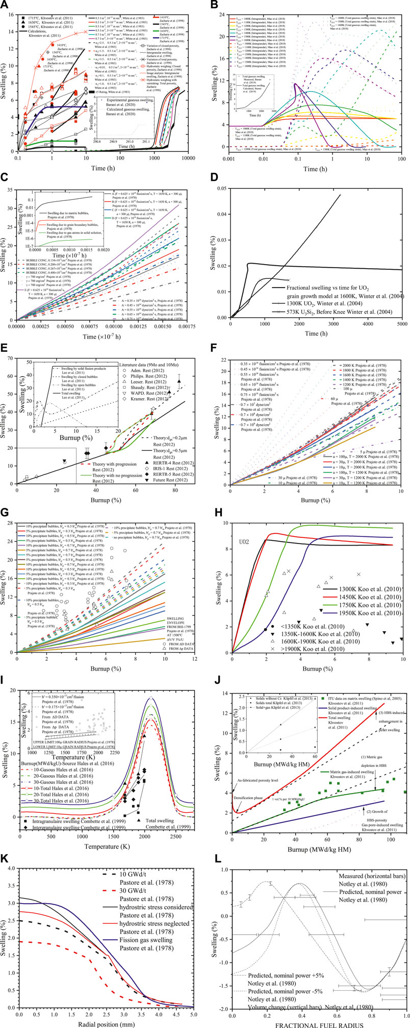
FIGURE 5. (A–D) Swelling with time in the UO2, UC, and U3Si2 fuels (Khvostov et al., 2011; White et al., 1983; Zacharie et al., 1998; Barani et al., 2020; Miao et al., 2018; Barani et al., 2019; Prajoto et al., 1978; Winter et al., 2004). (E–H) The swelling with burnup in the UO2, metallic and UC fuels (Prajoto et al., 1978; Lee et al., 2001; Koo et al., 2010; Rest, 2012). (I–L) The swelling in the UC and UO2 fuels with temperature, in the UN and UO2 fuels with radial position, and in the UO2 fuel with fractional fuel radius (Prajoto et al., 1978; Notley et al., 1980; Combette et al., 1999; Khvostov et al., 2011; Klipfel et al., 2013; Pastore et al., 2013; Hales et al., 2016).
The swelling with the burnup percentage in the UO2, metallic, and UC fuels is summarized in Figures 5E–H. One of the swelling lines reaches its maximum first and then decreases with burnup in the metallic fuel (Figure 5E). The swelling quickly reaches a specific value and keeps the relatively stable level in UO2 (Figure 5H). The swelling rises with burnup in UC (Figures 5F,G).
The swelling lines first rise until they reach their maximums and then decrease with the temperature and increase with burnup in UO2. The swelling of UC varies with temperature, as shown in the embedded figure of Figure 5I. The swelling rises with burnup both in UN and UO2 (Figure 5J). The swelling drops with the radial position increase in UO2 (Figure 5K). The swelling changes with the fractional fuel radius in UO2 (Figure 5L).
Fission Gas Diffusion Coefficient
Forsberg and Massih (1985b) studied the diffusion theory of fission gas in UO2 using an equivalent sphere model. The concentration of gas atoms at the grain boundary varies with time and is thus regarded as a time-dependent boundary condition. Different equations are derived, such as time-dependent source term, diffusion constant, the density of gas particles, grain boundary solution and analytic expressions of the concentration for short and long times in the regime. Then the accumulation of gas atoms at the grain boundary is obtained by the above numerically treated solution, and the saturation is viewed as a standard for release.
Andersson et al. (2014) studied the diffusion model of Xe in the UO2 fuel under non-stoichiometry and irradiation conditions, and using the DFT and empirical potentials, calculated the model parameters. The solutions show that intrinsic and radiation-enhanced diffusion corresponds well with available experiments. In addition, the mechanistic aspects of the bulk fission gas model are better than the existing empirical approaches. The fission gas release was also simulated during an LWR fuel rod irradiation test. The FGR predictions agree well with the theoretical model and experimental data, which are better than existing empirical models, and the close connection makes physical diffusion mechanisms more transferable.
Cooper et al. (2021) studied UO2 mixed with Cr2O3, which increases grain size during fabrication. It is expected that FGR is reduced by large grain size as the rate-limiting intragranular diffusion step extends. The doping UO2 chemistry has an essential effect on FGR, and the diffusion of Xe was investigated using thermodynamics. BISON also demonstrated the Halden model through integral analyses on the fuel rod Cr2O3-doped UO2 in IFA-716.1 (Killeen, 1980), which has good correspondence. Comparing the results of Framatome simulation of power ramp tests draws the new multiscale diffusive model, which can improve the predictions. The fission gas diffusion of the doped UO2 is better than the available data and the empirical model for undoped UO2. The mechanistic model of fission gas diffusion to precisely capture the in-reactor performance of doped UO2 should consider the effect of large grains and enhanced fission gas diffusivity. Multi-scale modeling also offers support to assess the performance of other advanced fuels.
The Xe diffusion coefficient with temperature in the UO2, UN, and MOX fuels is summarized in Figure 6. Most diffusion coefficients dramatically decrease with temperature, and some drop significantly at first with temperature and then decrease gradually (Figure 6).
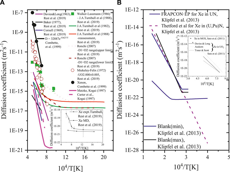
FIGURE 6. Diffusion coefficient with temperature in the UO2, MOX and UN fuels (Kogai, 1997; Combette et al., 1999; Sato et al., 2011; Klipfel et al., 2013; Rest et al., 2019).
Fuel Cladding Mechanical and Chemical Interactions
The fission gas release affects the cladding integrity through increased internal pressure when the current LWR fuel burnup is extended. The pellet–cladding mechanical interaction combined with high internal pressure results in the external mechanical restraint. The gaseous swelling at grain boundaries, connected with the formed release path, is affected and releases the fission gas. The external restraint will enforce on the fuel with the PCMI (pellet–cladding mechanical interaction) development under the steady-state condition. The amount of gas retained in the grain boundaries would rise but make the fission gas release delayed and reduced, determining the degree of the restraint. Gases are released by the variation of thermal stress of the micro-cracks, and the fission gas release increases with the external restraint in the previous steady-state operation because the number of gas atoms in the grain boundaries rises under the transient condition. The content of PCMI in high burnup fuel is determined by gaseous swelling which is narrow or already closed owing to the swelling of solid fission products and cladding creep-down controlled by the external restraint, which is also connected with the cladding integrity. Thus, the external restraint of fission gas release and gaseous swelling in high burnup fuel, where the PCMI probably exists, should be considered in the above two conditions (Koo et al., 2000).
Kocevski (2020) studied fuel–cladding interface interaction. The outcomes showed that the interaction results from vacancies require adequate energy to diffuse. The interaction coupled with diffusion was observed at higher temperature than lower temperature, as a result of limited interdiffusion analyzed by DFT. The cessation of fuel–cladding interactions is significantly increased with temperature owing to the formation of a devoid region in U3Si2 and SiC. This is arguable to regard it as a stable cladding system.
Pastore et al. (2015) investigated the uncertainties and sensitivities in fission gas behavior calculations in engineering scale nuclear fuel modeling. The results show that the calculated and measured FGRs agree with the uncertainty of the inherent model at high FGRs. The cladding diametral strain has a significant effect on fission gas behavior uncertainties during power transient.
Yingling et al. (2021) found that SiC cladding can be used together with high thermal conductivity fuels under normal operating conditions and low power density, which indicated that pellet clad contact can be avoided at an average burnup of 80 MWd/kgU in the nominal simulation. The performance of U3Si2–SiC is terrible at high power density and will undergo PCMI. Some sensitivities were shown to the variations of design parameters apart from the fuel to cladding gap, SiC irradiation swelling, etc. when U3Si2 operates at low temperatures. The fuel contacts with the cladding so that PCMI will cause failure readily owing to the little ductility of the SiC cladding. It results in a fragment relocation with fuel shuffling or introducing dislodged pellet chips in this fuel concept. Keeping fuel cladding from contact can be achieved by minimizing the thickness of the composite layer and not decreasing the hermeticity of the monolithic layer.
The swelling seriously affects the fuel performance because it will induce FCMI, which probably makes the lifetime of the fuel cladding shortened. It is confirmed by experiments that fuel–cladding chemical interaction exists during the post-irradiation. The fuel performance is affected by the interaction between the contained fission gases of the fuel and stainless steel cladding. The fuel–cladding chemical interaction probably limits the lifetime of the fuel pins by decreasing the cladding thickness. Cesium, chromium, iodine, and tellurium are observed in the zones of the interaction. The observed FCCI (fuel–cladding chemical interaction) data can be divided into three parts based on the results of micro-graphic examinations, including matrix, intergranular and combined interactions. The matrix interaction generally occurs in a wide area of the cladding surface, resulting in a uniform trans-granular corrosion. Intergranular interaction sporadically takes place in a localized zone of the inner surface that is limited to the grain boundaries of the cladding. Combined interaction is actually a sum of the above types of interaction (Karahan et al., 2009).
Liu et al. (2021) studied thorium-based fuel performance with Cr-coated SiC/SiC composite under both normal and accidental conditions. The results show that compared with the UO2–zircaloy system, the amount of fission gas release is reduced in this composite cladding, and the internal pressure of the fuel rod is dropped under the normal condition.
Clad wastage with temperature in the metallic fuel is summarized in Figure 7. The clad wastage increases with temperature, either dramatically and slow (Figure 7A). The clad wastage may considerably increase, not change, or slowly increase with temperature (Figure 7B).
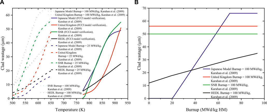
FIGURE 7. Clad wastage with (A) temperature and (B) burnup in the metallic fuel (Karahan et al., 2009).
Combined Fission Gas Behavior
UO2 Fuels
Hales et al. (2016) found that the FGR is induced by the fission gases xenon and krypton in nuclear fuel, significantly affecting the fuel rods. These fission gases tend to get into the bubble causing fuel swelling, which accelerates pellet–cladding gap closure and mechanical interaction. The gap pressure will build up, and the thermal conductivity of the rod filling gas will degrade when FGR to the fuel rod free volume. Fission gas atoms are produced in the fuel grains arriving at the grain boundaries via trapping and irradiation-induced resolution from intragranular gas bubbles. Irradiation will make the minority of the gas atoms return to the grain interior. Most gases will enter the grain-face gas bubble, inducing grain-face swelling. Bubble coalescence and inter-connection, caused by bubble growth, finally create a tunnel network, through which some gas diffuse to the fuel rod free volume.
The fission gas release to the fuel rod free volume is
The fractional volume grain-face fission gas swelling is
Volumetric swelling is
The fuel–cladding chemical interaction is
Liu et al. (2016) modeled the UO2–SiC fuel performance in LWR by using CAMPUS (CityU Advanced Multiphysics Nuclear Fuels Performance with User-defined Simulations), for instance, the swelling of the solid and gaseous fission products, the generation, diffusion and release of the fission gas, grain growth, pellet–cladding interaction, and gap/plenum pressure under irradiation condition. The results show that UO2–SiC can improve the abovementioned phenomena because of the unique and superior properties of SiC, which improves the safety of the reactor operation. Liu et al. (2015) modeled UO2–BeO fuel in LWR by using COMSOL Multiphysics. The result shows that BeO has good properties reducing FGR and decreasing the gap/plenum pressure.
The grain boundary saturation (atoms/m3) is
The release rate to the grain boundary is
The pressure in the gap and plenum is computed based on the ideal gas law,
The kinetics of grain growth is
The limiting grain size (m) is
Cooper et al. (2021) studied UO2 mixed with Cr2O3, which increases the grain size during fabrication. It is expected that the FGR is reduced by large grain size as the rate-limiting intragranular diffusion step extends. The doping UO2 chemistry has an essential effect on the FGR and the diffusion of Xe through thermodynamics calculations. BISON also demonstrated the Halden model through integral analyses on the fuel rod Cr2O3-doped UO2 in the IFA-716.1, which has a good agreement. The Framatome simulation results of power ramp tests conclude that the new multiscale diffusive model can improve the predictions. The fission gas diffusion of doped UO2 is better than the available data and the empirical model for the undoped UO2. The mechanistic model of fission gas diffusion can precisely capture the in-reactor performance of doped UO2 by considering the effect of large grains and enhanced fission gas diffusivity. Multi-scale modeling offers support to assess the performance of other advanced fuels.
Rahmani (2017) created a new method for improving the effect of fission gas products and examined fission gas release models based on the first cycle of Bushehr’s VVER (Water-Water Power Reactor in English)-1,000 reactor studying the feasibility of the proposed solution. The result shows that fission products with chabazite tubes substitute burnable absorbers can improve the thermal–hydraulic parameters and reactor cycle length. The gap pressure can be approximately restricted to the primary equilibrium level by this method. The end of the 4-year cycle is better than the that of first cycle in the effect of thermal–hydraulics in reducing fission products. Chabazite tubes possibly absorb released fission gases during the cycle. Using the Mason method, modeling FGR and calculating the gap pressure by WERL code indicated that decreasing grains’ diameter can increase fission products.
Combette et al. (1999) studied swelling and fission gas release. The intergranular swelling is observed, and xenon diffusion is explained. The relationship between them is analyzed and found out. The FGR experimental data correspond well with the Evans model.
An empirical xenon diffusion coefficient is
Koo et al. (2000) studied the swelling and fission gas release model in the UO2 fuel, which considered the effect of PCMI encountered at high burnup. The grain bubble swelling at the grain edge results from the formation of release tunnels. The FGR data of LWR fuels during irradiation are summarized in Table 6. The FGR data of LWR fuels at the end of life are summarized in Table 7.
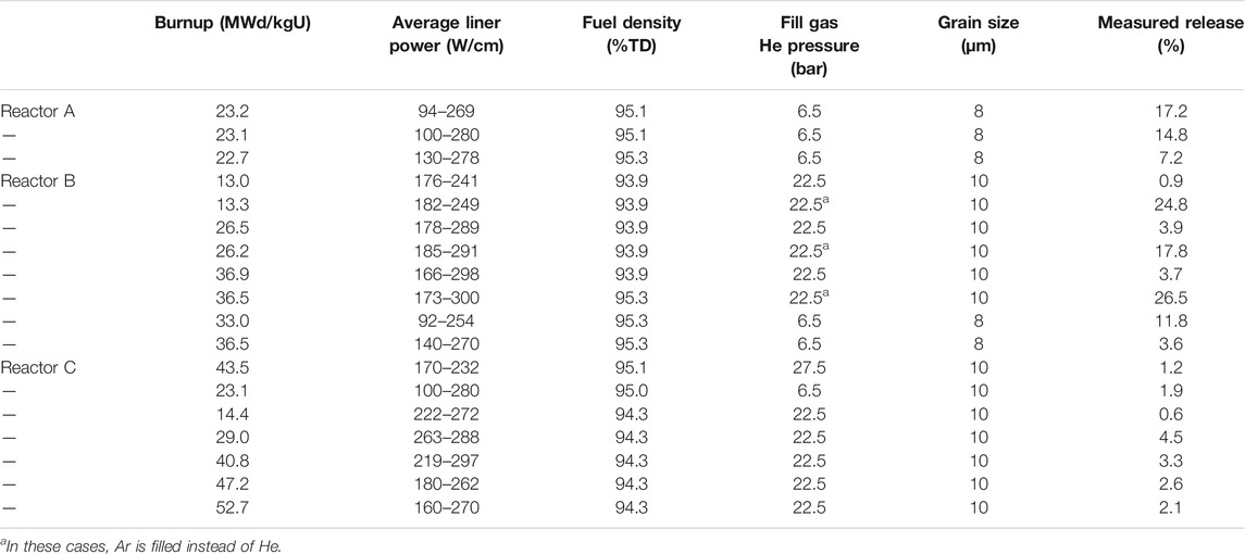
TABLE 6. Fission gas release data obtained from LWR fuels subjected to no power ramps during irradiation (Koo et al., 2000).
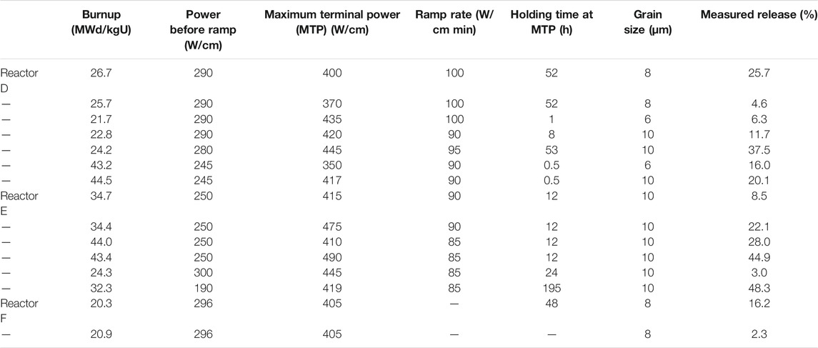
TABLE 7. Fission gas release data obtained from LWR fuels subjected to a power ramp at the end of life (Koo et al., 2000).
Before the grain face is saturated, the gas release rate is
After the saturation of grain face, the gas release rate is
The additional release rate of fission gas from the matrix to the grain boundary by grain growth is
The increasing rate of fission gas concentration at each grain edge due to grain growth is
The fractional volume swelling of the grain edge bubbles is
Pastore et al. (2015) found that a better gas atom diffusion coefficient can improve the fission gas behavior, the progress of the intra-granular gas atom resolution, and grain growth. Intrinsic uncertainties that may exceed physical details affect the engineering purposes of the fission gas behavior. The accurate prediction will increase model complexity; fitting model parameters to the experimental data obtains a limited number of cases, whose solution has higher accuracy, and the model applying different fuel design or irradiation conditions would not improve the confidence in the predictions.
The intragranular gas atom diffusion coefficient is
The grain boundary diffusion coefficient is
Kogai (1997) studied numerically the behavior of fission gas atoms at high burnup. The model describes how to deal with the grain boundary. The gas retention in the pellet is caused by the athermal diffusion term of fission gas atoms in grain under irradiation, and natural release increases with temperature increase. Gaseous swelling was modeled by changing the number density of intergranular bubbles upon interlinkage, which appears to be saturated after the massive gas release. The variation of the stress state in the pellet makes gas release with power reduction, which can be solved by considering the effect of tensile stress on the grain boundary. The FGR was constantly predicted in a wide range of burnup, gas release, and porosity in the pellet, expressed as time-dependent terms. The simulation showed the decrease of gas release onset temperature with burnup well, and the retained fission gas can reproduce the gas release at power reduction in pellet, agreeing with the measurements well. The result shows that this relatively simple model can simulate the FGR and gaseous swelling of LWR fuels at high burnup. Local bubble swelling vs. burnup and fission gas concentration is shown in Supplementary Table S6, and the measured and predicted FGRs with the local bubble swelling and fission gas content are also summarized in Supplementary Table S6 (Kogai, 1997).
In early times, the accumulated gas release fraction is a function of time:
The fission gas fraction released after time t for early time is
The local fractional swelling is
The pellet swelling is
Khvostov et al. (2011) studied FGR, swelling, and microstructural evolution in the UO2 fuel under irradiation, high burnup, and subsequent slow or fast transients using the developed GRSW-A model, which predicts macroscopic characteristics of the fuel state through analyzing the meso- and micro-scopic FGR taking place in the fuel material. The intragranular and grain-boundary-related processes are modeled, for example, the diffusion of the single gas atoms, migration, irradiation-induced resolution, and growth of gaseous bubbles. The formation and growth of the gaseous pores result in intergranular swelling and FGR entering the free volume of the fuel rod. The intra- and intergranular behaviors are modeled as closely dependent on the phenomenon of intragranular fuel polygonization in the high burnup structure, taking place during low-temperature irradiation, comparable with the progress of the equivalent-grain growth at higher temperatures. Comparing the experimental data with the calculation of the FGR in the PWR fuel rod under the irradiation up to a burnup of about 70 MWd/kgU shows improved FALCON (A fuel behavior analysis and licensing code) results combined with the GRSW-A (a model to analyze the processes of fission gas release, gaseous swelling, and microstructural evolutions in the uranium dioxide fuel) analysis. The thermal release from the pellet bulk and athermal HBS-assisted release from the pellet periphery consist of FGR mechanisms probably essential to the improved result. The FALCON/GRSW-A calculation interpreted well the obtained data of the fuel pellet swelling. The pellet swelling calculations agree well with the data of a pellet burnup up to 100 MWd/kgU. The result indicates that the intragranular pellet swelling rate decreases with burnup results from the intragranular fission gas depleting on the pellet periphery, and is affected by the intragranular polygonization, making the onset and further growth of grain-boundary bubble swelling owing to the transformation of the HBS (high burnup structure) pores. A linear relationship exists for both the total pellet swelling and burnup. The integral experiment REGATE (one of the experiments of the Fuel Modeling at Extended Burnup (FUMEX-II) Program) is comparable with the FALCON/GRSW-A in prediction, and is a sufficiently proposed approach for the base irradiation and a power ramp. Power ramp can result in a significant impact on the gaseous swelling and the residual cladding strain.
The fractional volume of the fuel affected by the high-temperature equiaxed-grain growth is
Pastore et al. (2013) analyzed the coupled phenomenon of fission gas release and swelling in the UO2 fuel by a developed physics-based model under irradiation. The model includes the fundamental physical progress of gas diffusion into grains, growth, and gas release to the fuel rod free volume. The approach of grain face bubble coalescence used an improved White model. This model was assessed by the irradiation experiments of the IFPE data, whose predictions agree well with the available experimental data of grain-face swelling. The results show that the TRANSURANUS code in this model agrees well with the data in the literature and describes well the fission gas release and swelling coupling, resulting in an accurate prediction for integral FGRs. The development of the TRANSURANUS code considers the local hydrostatic stress of the fuel rod behavior for the fission gas release and swelling during the PCMI, which can extend the burnup discharging and flexible usage of the nuclear fuel. The experimental data of grain-face swelling are summarized in Supplementary Table S7 (White et al., 2006; Pastore et al., 2013). The grain-face bubbles induced swelling of the irradiated fuel is studied by scanning electron microscopy (SEM) examinations.
The fractional volume intragranular swelling, normalized to the unit volume of the fuel, is
The fractional volume grain-face swelling, normalized to the unit volume of fuel, is
The effective gas diffusion coefficient is
White et al. (1983) developed a theoretical model which features the kinetics of irradiated UO2 fuel releasing fission gases and unstable fission products. The stable FGR is assumed to be delayed until a stable net of bubbles is built on the grain faces. Irradiation-inducing resolution delays the onset of release and varies the final gas release rate. The collapse of interconnected tunnels leads to grain corner porosity, and the swelling rate increases when the grain edge tunnels grow. Unstable passing gas atoms from the inner to the outer of the fuel are delayed due to the “periodic queuing,” and we regard the progress of diffusion as one of the release mechanisms by the deterioration of the poly-granular fuel. This model is comparable with the experiments of Turnbull and Friskney in releasing Xe133, Xe138, and other gas atoms from spherical compacts of 1.46%-enriched stochiometric UO2. The results indicate that other factors may contribute to discrepancies between the model and experiment in documented fuel history, which results from the uncertainties in the fission gas and unstable fission product diffusion coefficients. This model can be used to analyze the experiments and estimate the modified diffusion coefficients.
The swelling due to the grain bubbles is
where
Tc < 1,000°C: G = 0.0.
1,000°C < Tc < 1950°C: G=(Tc-1000)/9,500.
1950°C < Tc < 2,500°C: G = 0.4014–1.545 × 10⁻⁴Tc.
2,500°C < Tc: G = 1.5 × 10⁻².
1,000°C < Tc < 1950°C:
1950°C < Tc < 2000°C:
2000°C < Tc < 2,500°C:
2,500°C < Tc:
Notley (1980) studied FGR in the UO2 fuel, including diffusion, the accumulation and interlinkage of bubbles at the grain boundary, and grain boundary movement by a simplified model. This model results compare well with the FGR experimental data from irradiated UO2 fuel elements during a range of PHW reactor operation, liner powers between 40 and 120 kWm−1, burnups from 10 to 300 MWh (kgU)−1, steady-state and transient operational conditions. The burnup of higher gas releases was predicted in irradiated fuel exceeding 1,000 MWh (kgU)−1. The fuel swelling and degree of structural transformation were estimated and compared with the obtained data, which shows that fission gas and burnup in UO2 are extremely sensitive to the fuel power (temperature) and diffusion coefficient in the model predictions. However, the model predictions are hardly affected by the variation of fuel restraint, initial grain size, and grain growth rate. The natural UO2 grain growth is
The enriched UO2 grain growth is
Zacharie et al. (1998) studied the FGR and swelling in the thermally treated PWR UO2 fuel under irradiation. Swelling and release can rapidly increase with temperature in the first 60 min of treatment and then slowly vary, only observing the intragranular bubbles at 1715°C that merely affect overall swelling, the formation of tunnels at the opening grain boundaries can control release in the first few minutes, and the process can be controlled by the diffusion of fission gas atoms in the matrix into the grain boundaries since the tunnels are formed. It came up with an interpretation of the fission gas atoms under thermal treatment. First, the coalescence of bubbles controls swelling and release. Second, coalescence lets swelling continue, and diffusion of fission gas in the matrix into the tunnel at the grain boundaries causes release.
By hydrostatic weighing measurements, the swelling is
By image analysis measurements, the swelling is
The experimental data were compared to a theoretical model of fission gases released by atomic diffusion:
The diffusion coefficient of the xenon atoms is
Paraschiv et al. (1997) studied the FGR in the oxide fuels during normal grain growth. The results show that the grain size distribution can be described as functions of Hillert, Lifshitz, and Slyozov models in normal grain growth; the grain growth rate constant varies with time; and the normal grain growth is related to the prior developed grain growth model, which is regarded as the irradiation effect due to the solid fission products and intergranular fission gas bubbles. The thermodynamic forces are on the grain boundaries in normal grain growth, and the equivalent fission gas concentration is also on the boundaries. A single type of fuel grains and up to a constant diffusion from the same sphere combined with the average volume grain are evaluated close to the actual situation. It concluded that a considerable difference exists in the FGR predictions of Hillert, Lifshitz, and Slyozov models. The FGR models using two theories of normal grain growth and the approximate diffusion form a constant of identical average grain volume spheres. Lifshitz and Slyozov’s theory for normal grain growth in the FGR predictions and the average volume grain is lower, resulting from the predicted smaller grain sizes at the last stage of irradiation. The mathematical formalism can better describe FGR at the grain boundaries of the fuel samples as simulating the FGR results in the out-of-pile annealing tests.
MOX Fuels
Fisher et al. (2002) studied the microstructure and micro-chemistry of irradiated SBR (short binderless route) MOX fuel and compared IDR (integrated dry route)-UO2 with other MOX fuels. The results showed that the irradiation-induced parameters in the two fuels, for instance, fission gas production rate, fission gas diffusion, and grain growth, are the same. A well-developed grain boundary bubble network was observed in the SBR fuel but not the other irradiated MOX fuels during PWR normal operation. The characteristic of the Pu in irradiated SBR MOX seems to be different from the OCOM and MIMAS [Micronized master blend (Belgonucléaire)] MOX fuels, for example, the internal fission gas bubbles are developed in the cold outer half of the lower part of the fuel. However, some critical differences exist between them. Merely about 4% fission gas is released in the Pu spot in the SBR MOX fuel. The release takes place in the central region of the pellet during normal operations. Most fission gas generated in the Pu spots is accumulated in the adjacent grains by a network of recoil and diffusion due to the small size of Pu. Most fission gas is produced in the much larger Pu-rich inhomogeneous regions, mainly in pores, even in the pellet center. The Pu spots generate Xe, causing the perturbation in the SBR MOX fuel well in the natural variation in grain boundary swelling in UO2. The grain boundary swelling occurs at the highest temperature zone, and its overall release corresponds with local release requiring a higher fraction of gas diffusing to boundaries demonstrated by EPMA (electron probe microanalysis) measuring at Xe loss of 12–15%, the majority of which has diffused from the neighboring regions to boundaries in the central zones. The SBR MOX three cycles of the irradiated microstructure and micro-chemistry agree with measured FGR and with release mechanisms of UO2. The higher irradiated temperatures in the MOX fuel result in different behaviors, with lower thermal conductivity and higher third-cycle rating enforced by operational constraints. These characteristics are consistent with UO2 based on the Enigma code.
The proper grain size predicts local and overall gas release and gas diffusion to boundaries. The measured intergranular bubble and the calculated swelling are shown in Supplementary Table S8 (Fisher et al., 2002). The three images in Figure 8, 1a, 1b, and 1c, show grain face swelling in the range of 0.6–1.2%. The burnup of the UO2 samples is 21 MWd/kgHM. The MOX fuel was one-cycle fuel commercially irradiated to 11.5 MWd/kgHM, and the UO2 fuel had been irradiated in the Halden reactor to 9 MWd/kgHM (Figure 8. 2a and 2b). The annealing tests were nominally identical; after conditioning at 1,000°C, the fuel was ramped to 1900°C at 0.5°C/s and then quenched. The final temperature reached 1876°C in the MOX fuel, and the gas release was 6.2%, and at the same temperature, this number was 4.5% in the UO2 fuel (Figure 8. 1a, 1b, and 1c).
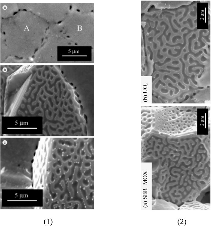
FIGURE 8. SEM images (left) of intergranular bubbles in (1a) SBR MOX CT10 transverse polished section, (1b) grain face in an AGR (Advanced Gas-cooled Reactor) UO2 sample which released 5.4% of the fission gas inventory during annealing at 0.5°C/s to 1900°C, and (1c) grain face in an AGR UO2 sample which released 7.4% of the fission gas inventory during annealing at 20°C/s to 1700°C. SEM images (right) of grain faces decorated with gas bubbles after post-irradiation annealing: (2a) SBR MOX fuel and (2b) AGR UO2 fuel (Fisher et al., 2002).
The volumetric swelling is
Denis et al. (2003) simulated fuel–cladding thermomechanical interaction and FGR. The results show that the code reoccurs the experimental data well referring to the irradiated fuel rods, the fuel central temperature, and the fractional gas release has a good agreement, especially in the zones at consistent power. However, the results are more inferior in the zones of fast decreasing power, even in other codes.
The swelling due to intragranular gas bubbles is
The swelling due to intragranular gas bubbles is
The swelling due to fission products in the lattice is
The swelling due to densification is
Metallic Fuels
Lee et al. (2001) studied the mechanistic of the FGR and swelling for the U–Pu–10Zr metallic fuel in the fast reactor by developing the GRSIS (Gas Release and Swelling in ISotropic fuel matrix) model. Grain sizes classify fission gas bubbles, which can be divided into three classes. Bubble interconnection takes place in forming an open passage to the outer free space as bubbles swell up to the threshold value, which makes fission gases of the interconnected bubbles’ inner release naturally. Bubble swelling also results in the fuel gap closure that can be considered in the model. Even if fuel swelling at the low temperature in the GRSIS is not taken into account, it could predict the universal behavior in the metallic fast reactor fuels. The results show that the gas atom diffusion has a significant effect on the FGR enhanced with temperature, but it has little influence on grain size, bubble nucleate rate, and fission density. Further investigation and modification are the classifications of the bubble sizes and values of other variables in the GRSIS.
Karahan et al. (2009) studied thermal–mechanical and irradiation behavior in the metallic and oxide fuels for sodium fast reactors by modeling FEAST-METAL using FORTRAN-90, including the optimized FGR and swelling model for metallic fuels; fuel–clad chemical interaction model represents the kinetics behavior under steady and transient conditions, and the transient physics-based approach of creep-fracture. The code testing reproduced the EBR-II experimental results under the above conditions. The model tracked the nucleation and growth of the cavities at the grain boundaries. The FEAST-OXIDE code is similar to the FEAST-METAL, in which one of the features was the advanced FGR and swelling model using vacancy flow. The code FEAST-OXIDE, EBR-II, FFTF, and JOYO experimental data under steady-state conditions agree well with the LIFE-4 in prediction outcomes, but the code FEAST-OXIDE predicts well the slow ramp overpower tests during the transient condition of EBR-II. The variables used in FEAST and GRSIS are shown in Supplementary Table S9 (Karahan et al., 2009), and the fuel specifications for TOP-1D test elements are shown in Supplementary Table S10 (Karahan et al., 2009).
An empirical model is as below:
The fission gas release can be calculated as follows:
The swelling volume by the open and closed bubbles is
The total swelling becomes as follows:
The thickness of the clad wastage layer is then
The HEDL model is as below:
The United Kingdom model is
The SNR model is
Rest (2012) simulated fission-gas-induced swelling theoretically in the UO2 and U–Mo fuels. The results show that the athermal diffusion of gas atoms, the formation of interstitial loops, and the uranium interstitial are classified to recrystallization owing to the material defect behavior in the temperature regime, whose calculations agree well with the data available. The measured pre- and post-irradiation-induced recrystallizations correspond well with the calculation of intergranular bubble-size distributions in the U–10Mo metallic fuel made with a mechanistic model of grain-boundary bubble formation kinetics. The bubble distribution behind re-crystallization varies with the same physical kinetics because of the change of bubble ahead of re-crystallization as a result of gas content and initial and/or boundary conditions.
The fraction of gas release is
The fractional swelling is
U3Si2 Fuels
Cappia et al. (2019) studied the U3Si2 fuel performance under irradiation at the LWR operational temperature and a burnup lower than 20 GWd/tHM using the destructive or not PIE, whose results show that FGR and swelling are restricted at low burnups. The accumulation of fission products and irradiation damage is subjected to a minor hardening of the fuel matrix demonstrated by micro-indentation tests.
Marquez et al. (2020) modeled the fuel swelling in U3Si2. The results showed that the gain is promoted to be subdivided by moderated temperature and high burnup, namely, regarding high swelling as boundary conditions. It is challenging for the grain to be subdivided at higher temperatures and lower burnup. The average burnup levels are lower than the threshold when operating at high temperatures but not exceeding the temperature limit of pellet melting for the silicide fuel. The silicide fuel is in possession with high thermal conductivity. The fuel swelling is implicated by a reduction of the influence of recrystallization on bubble formation and growth. Although the fuel swelling is alleviated by fission gas release, some potential fuel performance and design uncertainties exist.
Gamble et al. (2021) predicted the diffusion coefficient contributions to Xe diffusivity by using cluster dynamic simulations and the athermal contribution as a result of atomic mixing under the ballistic cascades through MD (Molecular Dynamics) simulations. The abovementioned contributions to Xe diffusivity were substituted by the physics-based fission gas release model in BISON. The results showed that the intergranular diffusion coefficients of Si vacancies were comparable with reference data in the literature. These coefficients determine the gaseous swelling of the fuel.
UN Fuels
Klipfel et al. (2013) studied the fission product behavior in UN by VASP (Vienna Ab initio Simulation Package), relaxed all structures, and calculated incorporation energies. The stability of the fission product in the UN matrix was provided by incorporation energies. Incorporating an FP (fission product) at an interstitial position in the UN requires considerable energy. Therefore, FP migration by an interstitial mechanism does not emerge. A conclusion can be drawn from the investigated incorporation and migration mechanisms that the incorporation energies for all FP’s are lowest at the single U vacancy, or at U vacancy, a Schottky defect causes fission products in UN primarily to migrate along the U-U vacancy. The fission products’ substitution result is assessed from the variation of the local volume by VASP and related with the fission product concentrations derived from SCALE (a comprehensive modeling and simulation suite for nuclear safety analysis and design). The prediction of fission products’ swelling in UN is similar to that in the UO2 fuel. Providing that fission products do not interact or form secondary phases, the liner swelling of nitride fuel obtains an estimation of the swelling rate as a function of time by comparing with empirical expressions in the literature. The mechanistic model of the fission gas behavior in nitride fuels is close to that for the UO2 fuel. It is needed in the fuel performance code to predict macroscopic fuel behavior, particularly segregation and secondary phases at higher temperatures and burnups.
The prediction of total swelling is
UC Fuels
Prajoto et al. (1978) studied the FGR and swelling behavior in carbide fuels under steady-state conditions by model and simulation based on the assumption of fission gas bubbles remaining stationary. The fast growth rate of bubbles in the experiment is reduced as a resolution parameter. Intragranular bubbles of gas atoms migrating to the grain boundary are related to swelling, and the accumulation of gas atoms causes the growth of grain boundary bubbles and grain boundary interlinkage, which takes place at high burnup levels. Grain boundary bubbles larger than intragranular bubbles have little influence on swelling since the restricted arrangement of bubbles on the grain boundary region. Although the absolute magnitude of gas atoms in solid solution in the matrix relies on reactor irradiation conditions, there is little effect on swelling. Gas release affects the results of the calculations only for the zones in the immediate adjacent-hood of the grain boundary for 2 years of irradiation at 1650 K. The results show that the predicted volume swelling and gas release are greatly affected by the variation of the resolution parameters. Although the gas atom concentration is affected by the diffusion constant in the matrix, the results are similar to the only relationship with the diffusion constant and for critical irradiation temperature, as gas atoms of solid solution compose only a small fraction of all the gas atoms contained in the fuel matrix (Prajoto et al., 1978).
The fraction of gas released to the grain boundary is
The overall fractional volume swelling due to gas atoms is
Hurst using Ritzman’s data:
Brinkman:
The gas atom diffusion coefficient is
TRISO Fuels
Zhang et al. (2020) studied fission product swelling and fission gas behavior in the TRISO particle fuel using the multidimensional multiphysics fuel performance analysis technique based on COMSOL Multiphysics. The results show that this model could predict FGR and swelling in both grain size and fuel particle pellet scale. The proportion of FGR and gaseous swelling were merely affected by the model.
The fractional gas release is
The plenum pressure is
Discussion
Significant uncertainties exist in the nuclear fuel behavior modeling even if many simulations and experiments have been developed and improved. Some properties are not well understood, resulting in these uncertainties, such as thermal diffusivity, gas bubble resolution rate, and gas bubble nucleation characteristics, and materials are significantly impacted by the rigorous reactor operating conditions. Thus, understanding the fission gas behavior in nuclear fuels is not easy because of a restricted preliminary study of the behavioral mechanisms (Yun et al., 2013).
The uncertainties exist in the behavioral mechanisms, material properties, and other critical parameters, and validation and verification are essential themes in the fission gas release modeling in nuclear fuels. The model validation is achieved by moderating these properties and parameters to compare the results with the measured gas release and swelling. Furthermore, the uncertainties of these properties and parameters create an inherent uncertainty in the validity of the underlying physics of the proposed behavior mechanisms. The predictive aspects of any mechanistic approach to describe the phenomena are ambiguous because of the inherent uncertainties so that more and more detailed data are needed to solve these problems (Rest, 2012).
Conclusion
Fission gas behaviors are essential to reactor integrity and nuclear safety. This review summarizes the primary fission gas behaviors in different fuels for both simulations and experiments. The fission gas behaviors are induced by many factors. It dominantly consists of fission gas release, gap/plenum pressure, grain growth, swelling, xenon diffusion coefficient, and fuel cladding mechanical and chemical interactions. The fission gas behaviors varying with specific parameters are summarized as follows:
Fission gas release with burnup, time, and temperature
Gap/plenum pressure with burnup and time
Grain growth with temperature and time
Swelling with time, burnup, temperature, radial position, and fuel radius
Fission gas diffusion coefficient with temperature
Clad wastage with temperature and burnup
Predicted and measured fission gas release
Predicted and measured grain growth
The fission gas behaviors are mainly subjected to burnup, time, and temperature, which profoundly impact these behaviors. Under the irradiation condition, the fission gas release will generally rise with burnup in the myriad of fuels. However, a dropping tendency does exist in very few fuels. The FGR will be enhanced with time and temperature in various fuels. In many cases, the predicted FGR is close to the measured one. The gap/plenum pressure will increase with burnup and time in most fuels, while it will decrease with burnup and time in some UO2 and U3Si2 fuels. Grain size will rise with temperature and time. The predicted radii are similar to the measured radii in most cases. Swelling will increase with time in many fuels and drop with time in some U3Si2 and metallic fuels. The swelling will rise to its maximum and then decrease with temperature in some UO2 fuels. The swelling will drop with radial position and fluctuate with fuel radius in some UO2 fuels. The xenon diffusion coefficient will decrease and then keep a stable value with temperature in a variety of fuels. Clad wastage will increase with temperature and burnup in the metallic fuel. In two cases, clad wastage with burnup in the metallic fuel keeps a constant number.
It can be concluded that burnup will motivate the fission gas release and other fission gas behaviors. With the fuel temperature increase, the extent of some fission gas behaviors will be strengthened more and more, including fission gas release, gap/plenum pressure, grain growth, swelling, and fuel–cladding mechanical and chemical interactions. The predicted data are consistent with the measured data, demonstrating that the modeling results agree well with the experimental data. In addition, the observation of enhanced gas release at high burnups is unexpected. The modeling approaches on fission gas release behaviors still have certain uncertainties. Therefore, it still has considerable space to be improved and is worth studying in future work.
Author Contributions
The work is mainly done by JG. JW and HL contributed to the accomplishment of this work, and WZ is the advisor of JG.
Funding
The financial support from Nuclear Power Technology Innovation Center of China (No. 45000–41020012), the Fundamental Research Funds for the Central Universities of China (No. 45000–18841210), the International Sci and Tech Cooperation Program of Guangdong Province (No. 2019A050510022), and Guangdong Major Project of Basic and Applied Basic Research (No. 2019B030302011) is highly appreciated.
Conflict of Interest
The authors declare that the research was conducted in the absence of any commercial or financial relationships that could be construed as a potential conflict of interest.
Publisher’s Note
All claims expressed in this article are solely those of the authors and do not necessarily represent those of their affiliated organizations, or those of the publisher, the editors, and the reviewers. Any product that may be evaluated in this article, or claim that may be made by its manufacturer, is not guaranteed or endorsed by the publisher.
Supplementary Material
The Supplementary Material for this article can be found online at: https://www.frontiersin.org/articles/10.3389/fenrg.2022.766865/full#supplementary-material
References
Aagesen, L. K., Andersson, D., Beeler, B. W., Cooper, M. W. D., Gamble, K. A., Miao, Y., et al. (2020). Phase-field Simulations of Intergranular Fission Gas Bubble Behavior in U3Si2 Nuclear Fuel. J. Nucl. Mater. 541, 152415. doi:10.1016/j.jnucmat.2020.152415
Andersson, D. A., Garcia, P., Liu, X.-Y., Pastore, G., Tonks, M., Millett, P., et al. (2014). Atomistic Modeling of Intrinsic and Radiation-Enhanced Fission Gas (Xe) Diffusion in UO2±x: Implications for Nuclear Fuel Performance Modeling. J. Nucl. Mater. 451, 225–242. doi:10.1016/j.jnucmat.2014.03.041
Barani, T., Bruschi, E., Pizzocri, D., Pastore, G., van Uffelen, P., Williamson, R. L., et al. (2017). Analysis of Transient Fission Gas Behaviour in Oxide Fuel Using BISON and TRANSURANUS. J. Nucl. Mater. 486, 96–110. doi:10.1016/j.jnucmat.2016.10.051
Barani, T. (2020). Mechanistic Modeling of Fission Gas Behavior in Conventional and Advanced Nuclear Fuel. Moscow, Russia: Department of Energy, Doctoral Program in Energy and Nuclear Science and Technology.
Barani, T., Pastore, G., Magni, A., Pizzocri, D., Van Uffelen, P., and Luzzi, L. (2020). Modeling Intra-granular Fission Gas Bubble Evolution and Coarsening in Uranium Dioxide during In-Pile Transients. J. Nucl. Mater. 538, 152195. doi:10.1016/j.jnucmat.2020.152195
Barani, T., Pastore, G., Pizzocri, D., Andersson, D. A., Matthews, C., Alfonsi, A., et al. (2019). Multiscale Modeling of Fission Gas Behavior in U3Si2 under LWR Conditions. J. Nucl. Mater. 522, 97–110. doi:10.1016/j.jnucmat.2019.04.037
Barry, A. (2021). Experimental Measurements to Evaluate the Effects of Fuel Microstructure on Fission Gas Release in Thoria. Ann. Nucl. Energ. 151, 107933. doi:10.1016/j.anucene.2020.107933
Barry, A., Livingstone, S., and Floyd, M. R. (2019). Fission Product Release in Thoria and Urania Defective Fuel Experiments FDO-680 and FDO-681. J. Nucl. Mater. 516, 309–316. doi:10.1016/j.jnucmat.2019.01.044
Beeler, B., Andersson, D., Cooper, M. W., and Zhang, Y. (2019b). A Molecular Dynamics Study of the Behavior of Xe in U3Si2. J. Nucl. Mater. 523, 413–420. doi:10.1016/j.jnucmat.2019.06.016
Beeler, B., Baskes, M., Andersson, D., Cooper, M. W., and Zhang, Y. (2019a). Molecular Dynamics Investigation of Grain Boundaries and Surfaces in U3Si2. J. Nucl. Mater. 514, 290–298. doi:10.1016/j.jnucmat.2018.12.008
Bernard, L. C., Jacoud, J. L., and Vesco, P. (2002). An Efficient Model for the Analysis of Fission Gas Release. J. Nucl. Mater. 302, 125–134. doi:10.1016/s0022-3115(02)00793-6
Besmann, T. M., Ferber, M. K., Lin, H.-T., and Collin, B. P. (2014). Fission Product Release and Survivability of UN-kernel LWR TRISO Fuel. J. Nucl. Mater. 448, 412–419. doi:10.1016/j.jnucmat.2013.10.034
Burkes, D. E., Casella, A. J., Casella, A. M., Luscher, W. G., Rice, F. J., and Pool, K. N. (2015). Measurement of Fission Gas Release from Irradiated U-Mo Monolithic Fuel Samples. J. Nucl. Mater. 461, 61–71. doi:10.1016/j.jnucmat.2015.02.020
Cappia, F., and Harp, J. M. (2019). Postirradiation Examinations of Low Burnup U3Si2 Fuel for Light Water Reactor Applications. J. Nucl. Mater. 518, 62–79. doi:10.1016/j.jnucmat.2019.02.047
Che, Y., Wu, X., Pastore, G., Li, W., and Shirvan, K. (2021). Application of Kriging and Variational Bayesian Monte Carlo Method for Improved Prediction of Doped UO2 Fission Gas Release. Ann. Nucl. Energ. 153, 108046. doi:10.1016/j.anucene.2020.108046
Claisse, A., and van Uffelen, P. (2015). Towards the Inclusion of Open Fabrication Porosity in a Fission Gas Release Model. J. Nucl. Mater. 466, 351–356. doi:10.1016/j.jnucmat.2015.08.022
Colle, J.-Y., Hiernaut, J.-P., Wiss, T., Beneš, O., Thiele, H., Papaioannou, D., et al. (2013). Fission Product Release and Microstructure Changes of Irradiated MOX Fuel at High Temperatures. J. Nucl. Mater. 442, 330–340. doi:10.1016/j.jnucmat.2013.09.022
Combette, P., and Zacharie, I. (1999). Reply to the Comments by J.H. Evans about Two Papers ‘Thermal Treatment of UO2 Irradiated in a Pressurized Water Reactor: Swelling and Release of Fission Gases' and ‘Microstructural Analysis and Modelling of Intergranular Swelling of an Irradiated UO2 Fuel Treated at High Temperature' by I. Zacharie, S. Lansiart, P. Combette, M. Trotabas, M. Coster and M. Groos. J. Nucl. Mater. 275, 112–114. doi:10.1016/s0022-3115(99)00135-x
Cooper, M. W., Pastore, G., Che, Y., Matthews, C., Forslund, A., Stanek, C. R., et al. (2021). Fission Gas Diffusion and Release for Cr2O3-Doped UO2: From the Atomic to the Engineering Scale. J. Nucl. Mater. 545, 152590. doi:10.1016/j.jnucmat.2020.152590
Denis, A., and Soba, A. (2003). Simulation of Pellet-Cladding Thermomechanical Interaction and Fission Gas Release. Nucl. Eng. Des. 223, 211–229. doi:10.1016/s0029-5493(02)00390-4
Evans, J. H. (1996). The Role of Directed Bubble Diffusion to Grain Boundaries in post-irradiation Fission Gas Release from UO2: a Quantitative Assessment. J. Nucl. Mater. 238, 175–182. doi:10.1016/s0022-3115(96)00452-7
Finlay, M. R., Hofman, G. L., Rest, J., and Snelgrove, J. L. (2002). “Behaviour of Irradiated Uranium Silicide Fuel Revisited,” in International Meeting on Reduced Enrichment for Research and Test Reactors, Bariloche, Argentina.
Fisher, S. B., White, R. J., Cook, P. M. A., Bremier, S., Corcoran, R. C., Stratton, R., et al. (2002). Microstructure of Irradiated SBR MOX Fuel and its Relationship to Fission Gas Release. J. Nucl. Mater. 306, 153–172. doi:10.1016/s0022-3115(02)01247-3
Forsberg, K., and Massih, A. R. (1985a). Diffusion Theory of Fission Gas Migration in Irradiated Nuclear Fuel UO2. J. Nucl. Mater. 135, 140–148. doi:10.1016/0022-3115(85)90071-6
Forsberg, K., and Massih, A. R. (1985b). Fission Gas Release under Time-Varying Conditions. J. Nucl. Mater. 127, 141–145. doi:10.1016/0022-3115(85)90348-4
Gamble, K. A., Pastore, G., Cooper, M. W. D., Andersson, D. A., Matthews, C., Beeler, B., et al. (2021). Improvement of the BISON U3Si2 Modeling Capabilities Based on Multiscale Developments to Modeling Fission Gas Behavior. J. Nucl. Mater. 555, 153097. doi:10.1016/j.jnucmat.2021.153097
Hales, J. D., Williamson, R. L., Novascone, S. R., Pastore, G., Spencer, B. W., Stafford, D. S., et al. (2016). BISON Theory Manual, the Equations behind Nuclear Fuel Analysis, INL/EXT-13-29930 Rev. 3, Technical Report. Idaho Falls, USA: Idaho National Laboratory.
Hofman, G., Ye, B., Kim, Y. S., Keiser, D., Robinson, A., and Leenears, A. (2019). Projection of Irradiation Behavior of U3Si2-Al Dispersion Fuel at High Fuel Loading and High Power, International Meeting on Reduced Enrichment for Research and Test Reactors, ANL, INL, USA, SCK∙CEN, Belgium.
Hwang, W., Lee, B.-O., and Kim, Y. J. (2000). Recent Improvements in Modelling Fission Gas Release and Rod Deformation on Metallic Fuel in LMR. Ann. Nucl. Energ. 27, 1059–1069. doi:10.1016/s0306-4549(99)00109-7
Hy, B., Barré-Boscher, N., Özgümüs, A., Roussière, B., Tusseau-Nenez, S., Lau, C., et al. (2012). An Off-Line Method to Characterize the Fission Product Release from Uranium Carbide-Target Prototypes Developed for SPIRAL2 Project. Nucl. Instr. Methods Phys. Res. Section B: Beam Interactions Mater. Atoms 288, 34–41. doi:10.1016/j.nimb.2012.04.031
Ishida, M., and Korei, Y. (1994). Modeling and Parametric Studies of the Effect of Pu-Mixing Heterogeneity on Fission Gas Release from Mixed Oxide Fuels of LWRs and FBRs. J. Nucl. Mater. 210, 203–215. doi:10.1016/0022-3115(94)90238-0
Jeong, G. Y., Yang, Y. S., and Sohn, D.-S. (2015). Gas Releases and Rod Internal Pressure of BN-Added UO2fuel. J. Nucl. Sci. Technol. 52 (10), 1208–1216. doi:10.1080/00223131.2015.1009956
Jossou, E. E. (2019). “Atomic Scale Simulation of Accident Tolerant Fuel Materials for Future Nuclear Reactors,”. Ph.D. thesis (Saskatoon, Canada: University of Saskatchewan).
Karahan, A. (2009). “Modeling of Thermo-Mechanical and Irradiation Behavior of Metallic and Oxide Fuels for Sodium Fast Factor,”. Ph.D. thesis (Cambridge: MIT).
Khvostov, G., Mikityuk, K., and Zimmermann, M. A. (2011). A Model for Fission Gas Release and Gaseous Swelling of the Uranium Dioxide Fuel Coupled with the FALCON Code. Nucl. Eng. Des. 241, 2983–3007. doi:10.1016/j.nucengdes.2011.06.020
Killeen, J. C. (1980). Fission Gas Release and Swelling in UO2 Doped with Cr2O3. J. Nucl. Mater. 88, 177–184. doi:10.1016/0022-3115(80)90272-x
Kim, H.-C., and Cho, G. (1996). A Hexagonal Percolation Model for Zone-dependent Pore Interlinkage Fraction and its Application to the Prediction of Fission Gas Release. Ann. Nucl. Energ. 23 (18), 1445–1457. doi:10.1016/0306-4549(96)00047-3
Kim, Y.-s., and Lee, C.-b. (2008). Two-step Two-Stage Fission Gas Release Model. J. Nucl. Mater. 374, 431–436. doi:10.1016/j.jnucmat.2007.10.002
Kim, Y.-s. (2004). Theoretical Analysis of Two-Stage Fission Gas Release Processes: Grain Lattice and Grain Boundary Diffusion. J. Nucl. Mater. 326, 97–105. doi:10.1016/j.jnucmat.2003.12.014
Kim, Y. S., Hofman, G. L., Rest, J., and Robinson, A. B. (2009). Temperature and Dose Dependence of Fission-Gas-Bubble Swelling in U3Si2. J. Nucl. Mater. 389, 443–449. doi:10.1016/j.jnucmat.2009.02.037
King, W. E., Robel, M., and Gilmer, G. H. (2011). The Potential to Use Fission Gas Release Experiments to Measure Lattice and Grain Boundary Diffusion in Metallic Fuels. J. Nucl. Mater. 411, 97–111. doi:10.1016/j.jnucmat.2011.01.037
Klipfel, M., Di Marcello, V., Schubert, A., van de Laar, J., and van Uffelen, P. (2013). Towards a Multiscale Approach for Assessing Fission Product Behaviour in UN. J. Nucl. Mater. 442, 253–261. doi:10.1016/j.jnucmat.2013.08.056
Kocevski, V., Lopes, D. A., Claisse, A. J., and Besmann, T. M. (2020). Understanding the Interface Interaction between U3Si2 Fuel and SiC Cladding. Nat. Commun. 11. doi:10.1038/s41467-020-16435-x
Kogai, T. (1997). Modelling of Fission Gas Release and Gaseous Swelling of Light Water Reactor Fuels. J. Nucl. Mater. 244, 131–140. doi:10.1016/s0022-3115(96)00731-3
Koo, Y.-H., Lee, B.-H., Cheon, J.-S., and Sohn, D.-S. (2002). Modeling and Parametric Studies of the Effect of Inhomogeneity on Fission Gas Release in LWR MOX Fuel. Ann. Nucl. Energ. 29, 271–286. doi:10.1016/s0306-4549(01)00035-4
Koo, Y.-H., Lee, B.-H., and Sohn, D.-S. (2000). Analysis of Fission Gas Release and Gaseous Swelling in UO2 Fuel under the Effect of External Restraint. J. Nucl. Mater. 280, 86–98. doi:10.1016/s0022-3115(00)00034-9
Koo, Y.-H., Oh, J.-Y., Lee, B.-H., Tahk, Y.-W., and Song, K.-W. (2010). Artificial Neural Network Modeling for Fission Gas Release in LWR UO2 Fuel under RIA Conditions. J. Nucl. Mater. 405, 33–43. doi:10.1016/j.jnucmat.2010.07.032
Koo, Y.-H., Shin, C.-H., Jeon, S.-C., Kim, D.-S., Kim, K.-S., Kim, D.-J., et al. (2019). Fission Gas Release in the Micro-cell Fuel Pellet under normal Operating Conditions: A Simplified Approach Based on UO2 Pellet Experience. J. Nucl. Mater. 527, 151801. doi:10.1016/j.jnucmat.2019.151801
Lee, C. B., Kim, D. H., and Jung, Y. H. (2001). Fission Gas Release and Swelling Model of Metallic Fast Reactor Fuel. J. Nucl. Mater. 288, 29–42. doi:10.1016/s0022-3115(00)00718-2
Lewis, B. J., Chan, P. K., El-Jaby, A., Iglesias, F. C., and Fitchett, A. (2017). Fission Product Release Modelling for Application of Fuel-Failure Monitoring and Detection - an Overview. J. Nucl. Mater. 489, 64–83. doi:10.1016/j.jnucmat.2017.03.037
Liu, R., Zhou, W., Prudil, A., and Chan, P. K. (2016). Multiphysics Modeling of UO2-SiC Composite Fuel Performance with Enhanced thermal and Mechanical Properties. Appl. Therm. Eng. 107, 86–100. doi:10.1016/j.applthermaleng.2016.06.173
Liu, R., Zhou, W., Shen, P., Prudil, A., and Chan, P. K. (2015). Fully Coupled Multiphysics Modeling of Enhanced thermal Conductivity UO 2 -BeO Fuel Performance in a Light Water Reactor. Nucl. Eng. Des. 295, 511–523. doi:10.1016/j.nucengdes.2015.10.019
Liu, S., Liu, R., Qiu, C., and Zhou, W. (2021). Multiphysics Modeling of Thorium-Based Fuel Performance with Cr-Coated SiC/SiC Composite under Normal and Accident Conditions. Front. Energ. Res. 9, 677606. doi:10.3389/fenrg.2021.677606
Lӧsӧnen, P. (2002). Modelling Intragranular Fission Gas Release in Irradiation of Sintered LWR UO2 Fuel. J. Nucl. Mater. 304, 29–49.
Marquez, M. G., Ougouag, A. M., and Petrovic, B. (2020). Model for Radiation Damage-Induced Grain Subdivision and its Influence in U3Si2 Fuel Swelling. Ann. Nucl. Energ. 145, 105712. doi:10.1016/j.anucene.2017.08.045
Matsson, I., Grapengiesser, B., Grapengiesser, B., and Andersson, B. (2007). On-site -ray Spectroscopic Measurements of Fission Gas Release in Irradiated Nuclear Fuel. Appl. Radiat. Isot. 65, 36–45. doi:10.1016/j.apradiso.2006.07.004
Matzke, H. J. (1980). Gas Release Mechanisms in UO2-A Critical Review. Radiat. Effects 53 (3-4), 219–242. doi:10.1080/00337578008207118
Metzger, K. E., Knight, T. W., and Williamson, R. L. (2014). Model of U3Si2 Fuel System Using BISON Fuel Code, INL/CON-13-30445,14343, USA.
Miao, Y., Gamble, K. A., Andersson, D., Mei, Z.-G., and Yacout, A. M. (2018). Rate Theory Scenarios Study on Fission Gas Behavior of U3Si2 under LOCA Conditions in LWRs. Nucl. Eng. Des. 326, 371–382. doi:10.1016/j.nucengdes.2017.11.034
Miao, Y., Gamble, K. A., Andersson, D., Ye, B., Mei, Z.-G., Hofman, G., et al. (2017). Gaseous Swelling of U3Si2 during Steady-State LWR Operation: A Rate Theory Investigation. Nucl. Eng. Des. 322, 336–344. doi:10.1016/j.nucengdes.2017.07.008
Millett, P. C., Tonks, M. R., and Biner, S. B. (2012). Grain Boundary Percolation Modeling of Fission Gas Release in Oxide Fuels. J. Nucl. Mater. 424, 176–182. doi:10.1016/j.jnucmat.2012.03.006
Nanopoulos, D. (2017). “Mechanistic Modelling of Swelling in the Accident Tolerant Fuel Candidate U3Si2,”. Master’s thesis (Mukherjee Nagar, Delhi: KTH).
Notley, M. J. F., and Hastings, I. J. (1980). A Microstructure-dependent Model for Fission Product Gas Release and Swelling in UO2 Fuel. Nucl. Eng. Des. 56, 163–175. doi:10.1016/0029-5493(80)90180-6
Paraschiv, M. C., Paraschiv, A., and Glodeanu, F. (1997). On the Fission Gas Release from Oxide Fuels during normal Grain Growth. J. Nucl. Mater. 246, 223–231. doi:10.1016/s0022-3115(97)00039-1
Pastore, G., Luzzi, L., Di Marcello, V., and van Uffelen, P. (2013). Physics-based Modelling of Fission Gas Swelling and Release in UO2 Applied to Integral Fuel Rod Analysis. Nucl. Eng. Des. 256, 75–86. doi:10.1016/j.nucengdes.2012.12.002
Pastore, G., Swiler, L. P., Hales, J. D., Novascone, S. R., Perez, D. M., Spencer, B. W., et al. (2015). Uncertainty and Sensitivity Analysis of Fission Gas Behavior in Engineering-Scale Fuel Modeling. J. Nucl. Mater. 456, 398–408. doi:10.1016/j.jnucmat.2014.09.077
Prajoto, P., Wazzan, A. R., and Okrent, D. (1978). Computer Modeling of Steady State Fission Gas Behavior in Carbide Fuels. Nucl. Eng. Des. 48, 461–495. doi:10.1016/0029-5493(78)90092-4
Prudil, A. A., Colins, K. D., Thomas, E. S., and Welland, M. J. (2020). Intra- and Intergranular Fission Gas Transport on Large Irregular Hexagonal Grain Networks by an Included Phase Model. J. Nucl. Mater. 542, 152456. doi:10.1016/j.jnucmat.2020.152456
Prudil, A. A., Thomas, E. S., and Welland, M. J. (2019). Network Percolation Using a Two-Species Included Phase Model to Predict Fission Gas Accommodation and Venting. J. Nucl. Mater. 515, 170–186. doi:10.1016/j.jnucmat.2018.12.036
Rahmani, Y. (2017). Feasibility Study of Chabazite Absorber Tube Utilization in Online Absorption of Released Gaseous Fission Products and Substitution of Burnable Absorber Rods with Chabazite Absorber Tubes in VVER-1000 Reactor Series. Ann. Nucl. Energ. 102, 56–76. doi:10.1016/j.anucene.2016.12.020
Rest, J. (2004). A Model for Fission-Gas-Bubble Behavior in Amorphous Uranium Silicide Compounds. J. Nucl. Mater. 325, 107–117. doi:10.1016/j.jnucmat.2003.11.008
Rest, J., Cooper, M. W. D., Spino, J., Turnbull, J. A., van Uffelen, P., and Walker, C. T. (2019). Fission Gas Release from UO2 Nuclear Fuel: A Review. J. Nucl. Mater. 513, 310–345. doi:10.1016/j.jnucmat.2018.08.019
Sato, I., Katsuyama, K., and Arai, Y. (2011). Fission Gases and Helium Gas Behavior in Irradiated Mixed Oxide Fuel Pin. J. Nucl. Mater. 416, 151–157. doi:10.1016/j.jnucmat.2010.11.028
Storms, E. K. (1988). An Equation Which Describes Fission Gas Release from UN Reactor Fuel. J. Nucl. Mater. 158, 119–129. doi:10.1016/0022-3115(88)90161-4
Tonks, M., Andersson, D., Devanathan, R., Dubourg, R., El-Azab, A., Freyss, M., et al. (2018). Unit Mechanisms of Fission Gas Release: Current Understanding and Future Needs. J. Nucl. Mater. 504, 300–317. doi:10.1016/j.jnucmat.2018.03.016
Vaidyanathan, S., and Plumlee, D. E. (1993). A Model for Fission Gas Release from UN Fuel. AIP Conf. Proc. 271, 251. doi:10.1063/1.43236
Verdolin, F., Novascone, S., Pizzocri, D., Pastore, G., Barani, T., and Luzzi, L. (2021). Modelling Fission Gas Behaviour in Fast Reactor (U,Pu)O2 Fuel with BISON. J. Nucl. Mater. 547, 152728. doi:10.1016/j.jnucmat.2020.152728
Viswanathan, U. K., Sah, D. N., Rath, B. N., and Anantharaman, S. (2009). Measurement of Fission Gas Release, Internal Pressure and Cladding Creep Rate in the Fuel Pins of PHWR Bundle of normal Discharge Burnup. J. Nucl. Mater. 392, 545–551. doi:10.1016/j.jnucmat.2009.04.021
White, R. J., Corcoran, R. C., and Barnes, P. J. (2006). A Summary of Swelling Data Obtained from the AGR/Halden Ramp Test Programme. Tech. Rep. R&t/ng/ext/rep/0206/02.
White, R. J., and Tucker, M. O. (1983). A New Fission-Gas Release Model. J. Nucl. Mater. 118, 1–38. doi:10.1016/0022-3115(83)90176-9
Winter, T. C. (2016). “Comparison of Fission Gas Swelling Models for Amorphous U3Si2 and Crystalline UO2,”. Master’s thesis (Atlanta, GA, USA: Georgia Institute of Technology).
Winter, T., and Deo, C. (2017). Comparison of Fission Gas Swelling Models for Amorphous U3Si2 and Crystalline UO2. Ann. Nucl. Energ. 100, 31–41. doi:10.1016/j.anucene.2016.08.008
Wu, X., Kozlowski, T., and Meidani, H. (2018). Kriging-based Inverse Uncertainty Quantification of Nuclear Fuel Performance Code BISON Fission Gas Release Model Using Time Series Measurement Data. Reliability Eng. Syst. Saf. 169, 422–436. doi:10.1016/j.ress.2017.09.029
Yingling, J. A., Gamble, K. A., Roberts, E., Freeman, R. A., and Knight, T. W. (2021). UPDATED U3SI2 thermal Creep Model and Sensitivity Analysis of the U3SI2-SIC Accident Tolerant FUEL. J. Nucl. Mater. 543, 152586. doi:10.1016/j.jnucmat.2020.152586
Yun, D., Rest, J., Hofman, G. L., and Yacout, A. M. (2013). An Initial Assessment of a Mechanistic Model, GRASS-SST, in U-Pu-Zr Metallic alloy Fuel Fission-Gas Behavior Simulations. J. Nucl. Mater. 435, 153–163. doi:10.1016/j.jnucmat.2012.12.024
Zacharie, I., Lansiart, S., Combette, P., Trotabas, M., Coster, M., and Groos, M. (1998). Thermal Treatment of Uranium Oxide Irradiated in Pressurized Water Reactor: Swelling and Release of Fission Gases. J. Nucl. Mater. 255, 85–91. doi:10.1016/s0022-3115(98)00039-7
Zhang, C., Wu, Y., Liu, S., Chen, P., Li, W., Deng, C., et al. (2020). Multidimensional Multiphysics Modeling of TRISO Particle Fuel with SiC/ZrC Coating Using Modified Fission Gas Release Model. Ann. Nucl. Energ. 145, 107599. doi:10.1016/j.anucene.2020.107599
Glossary
a grain radius, μm
AECL Atomic Energy of Canada Limited
Agf: bubble projected area on the grain face
AGR Advanced Gas-cooled Reactor
ANN artificial neural network
ANS American Nuclear Society
ATF accident-tolerant fuel
B atom percent burnup in Eqs 7 and Eqs 8 and Eqs 9 of Section 2.5
B burnup (MWd/t) in Eq. 53 of Section 8.3
b: the rate of bubble resolution
BISON A Finite Element-Based Nuclear Fuel Performance Code
BO burnup at which O/M = 1.994 (oxidation of molybdenum starts)
Bu burnup, %
BWR boiling water reactor
C concentration of fission gas atoms in the fuel grains in Eq. 16 of Section 8.1
C solubility fraction of the fission product in Eq. 14 of Section 8.1
c the number of gas atoms in dynamic solution
CABRI a research reactor used to simulate a power transient in France
CAMPUS CityU Advanced Multiphysics Nuclear Fuels Performance with User-defined Simulations
CANDU Canada Deuterium Uranium, a Canadian pressurized heavy-water reactor
CB concentration
Cb: intergranular fission-gas bubble density
cb intragranular fission-gas bubble density
Cbl gas amount in intergranular bubble, m−3
Cf: solubility limit of the fission product
Cgb gas amount in grain boundary, m−3
Cgb1: concentration of gas atoms present as bubble-1 in the matrix, atoms/m3
Cgb2 concentration of gas atoms present as bubble-2 in the matrix, atoms/m3
Cgb3 concentration of gas atoms present as bubble-3 in the matrix, atoms/m3
D clad wastage (μm) in Eqs 53 and 54, 55 and 56 of Section 8.3
D diffusion coefficientgas atom diffusion constant in the matrix in Eqs 60 and 62, 63 of Section 8.6
d final grain size, μm
D diffusion coefficient gas atom diffusion constant in the matrix in Eqs 60 and 62, 63 of Section 8.6
D’ an empirical coefficient in relation with the apparent coefficient D and the grain size a (D’ = D/a2)
d0 initial grain size, μm
D1: intrinsic thermal diffusion, m2/s
D2 irradiation-enhanced diffusion, m2/s
dav average grain diameter
DB the gas bubble density per unit area on the grain face
DFT density function theory
Dg the gas-atom diffusion coefficient
dg the grain boundaries of grains of diameter
DOE-NE Department of Energy’s Nuclear Energy Office
Ds the single gas atom diffusion coefficient in the UO2 lattice
dV/V volumetric strain
Ea constant activation energy, 445 kJ/mol
EOL end of life
EPMA electron probe microanalysis
f(θfg) a function that accounts for the shape of the bubbles
f fission gas release fraction in Eq. 49 of Section 8.3
f fission rate, m−3s−1
F fission rate, m−3s−1, in Eq. 26 of Section 8.1
F fractional coverage in Eq. 11 of Section 8.1
f fission rate, m−3s−1 grain edge swelling to the maximum grain edge swelling in Eq. 21 of Section 8.1
FALCON— a fuel behavior analysis and licensing code
FASTGRASS Fast Gas Release and Swelling Subroutine, A Mechanistic Model for the Prediction of Fission Gas Release
fB grain boundary fraction at saturation, 0.5
fBu burn-up factor
FCCI fuel-cladding chemical interaction
FEAST fuel engineering and structural analysis tool
FGR fission gas release
FP fission product
FRAPCON a computer code for the calculation of steady-state, thermal–mechanical behavior of oxide fuel rods
Fsat saturation coverage
ft (θ) geometric factor relating the volume of a grain face bubble to that of a sphere
fth fraction of closed bubbles that interconnect to the open bubbles when the threshold swelling is exceeded
FUMEX fuel modeling exercise
G fission gas fraction
G an empirical parameter deduced from AGR fuel post irradiation examinations in Eq. 36 of Section 8.1
g precipitation possibility in Eq. 60 Section-8.6
g rate of gas atom trapping into bubbles in Eq. 35 of Section 8.1
gb the number of gas atoms released to the grain boundary
gd average grain diameter (2gr)
gr grain radius
GRSIS Gas Release and Swelling in ISotropic fuel matrix
GSW-A A model to analyze the processes of fission gas release, gaseousswelling and microstructural evolutions in the uranium dioxide fuel
HBS high burnup structure
IAEA International Atomic Energy Agency
IFPE International Fuel Performance Experiments
INL Idaho National Laboratory
IPM Included Phase Model
J interaction layer thickness
k the Boltzmann constant, JK−1
k rate constant, 1.46 × 10⁻⁸exp(-32100/T) in Eq. 18 of Section 8.1
kB the Boltzmann constant
KEMS Knudsen effusion mass spectrometry
LIFE a computer analysis of fast-reactor fuel-element behavior
LOCA loss of coolant accident
LWR light-water reactor
m number of gas in intragranular bubbles
MACSIS Metal fuel performance Analysis (computer) Code for Simulating the In-reactor behavior under Steady-state conditions
MCMC Markov Chain Monte Carlo
MD molecular dynamics
MIMAS micronized master blend (Belgonucléaire)
MOX mixed oxide
MW molecular weight of the layer
N concentration
n moles of gas
Nb number density of bulk bubbles, bubble/m3
Nbl the number density of the bubble
Nd number density of bubbles at dislocations, bubble/m3
ng the mole of gas
Ngf bubble number density
Nig the number density of intragranular bubbles
NSRR Nuclear Safety Research Reactor in Japan
O/M as-fabricated fuel oxygen to metal atom ratio
OCOM Optimized CO-Milling
OECD/NEA Organisation for Economic Co-operation and Development/Nuclear Energy Agency
P gap/plenum pressure
P0 initial porosity
PCMI pellet-cladding mechanical interaction
Pext external pressure
PHENIX fast reactor in France
PHTS primary heat transport system
PHWR pressurized heavy-water reactor
PIE post irradiation examination
PWR pressurized water reactor
Q the heat of activation for atom diffusion per mole, 78 kcal/g∙atom
Qgb diffusion activation energy through the grain boundaries, kJ/mol
QR(t) the cumulative amount of gas atoms released up to time t to the free space of the fuel rod per unit volume of a grain
Qv diffusion activation energy through the grain lattice, kJ/mol
R gas constant (1.987 cal/mol/K) in Eq. 53 of Section 8.3
R ideal gas constant, 8.31Jmole−1K−1
R percent release in Eq 7 and Eq 8 and Eq 9 of Section 2.5
RB bubble radius
rb final bubble radius
Rb the grain boundary bubble nucleation radius
rbl bubble radius
REGATE one of the experiments of the Fuel Modeling at Extended Burnup (FUMEX-II) Program
rf grain boundary bubble radius, 5 × 10⁻⁷ m
Rg grain radius
Rgf bubble radius of curvature
rgf the radius of curvature of a circular grain face
rgr grain radius
RIA reactivity-initiated accident
Rig the mean radius of intragranular bubbles
RP mean bubble radius
Rtot(t) total number of gas atoms released from a UO2 pellet up to time t
SBR short binderless route
SCALE a comprehensive modeling and simulation suite for nuclear safety analysis and design
SCIANTIX an open source multi-scale code for fission gas behavior modelling
SEM scanning electron microscope
Sg total swelling of the open and closed bubbles
Sth threshold gas swelling
SUPERFACT experiments irradiation tests for oxide fuels containing minor actinides
T temperature, K
t: time, s
Tb the temperature of buffer
Tc central temperature (°C)
TD theoretical density percent of theoretical density
TD theoretical density percent of theoretical density
Tg the temperature of buffer and inner IPyC
TRANSURANUS a fuel performance code
TRISO TRi-structural ISOtropic particle fuel
UQ uncertainty quantification
V: volume of the cavity, m3
VASP Vienna Ab initio Simulation Package
Vb the gas-filled volume in buffer in Eq. 65 of Section 8.7
Vb volume of a bulk bubble, m3
Vd: volume of a dislocation bubble, m3
Vf fuel volume
Vg the current grain volume
Vg: the volume of gap in Eq. 65 of Section 8.7
Vi volume of bubble-i (m3)
Vpellet volume of the UO2 pellet, mm3
VV(P) (f) the volume fraction after treatment
VV(P) (i) the volume fraction before treatment
VVER Water-Water Power Reactor (Russian)
Wr the fuel rating (W/g)
Y the number of the gas atoms created per fission
Keywords: fission gas behaviors, swelling, nuclear fuels, models, experiments
Citation: Guo J, Lai H, Zhou W and Wei J (2022) Fission Gas Behaviors and Relevant Phenomena in Different Nuclear Fuels: A Review of Models and Experiments. Front. Energy Res. 10:766865. doi: 10.3389/fenrg.2022.766865
Received: 30 August 2021; Accepted: 12 January 2022;
Published: 04 March 2022.
Edited by:
Shripad T. Revankar, Purdue University, United StatesReviewed by:
Chaitanya Suresh Deo, Georgia Institute of Technology, United StatesAyhan Kara, Giresun University, Turkey
Copyright © 2022 Guo, Lai, Zhou and Wei. This is an open-access article distributed under the terms of the Creative Commons Attribution License (CC BY). The use, distribution or reproduction in other forums is permitted, provided the original author(s) and the copyright owner(s) are credited and that the original publication in this journal is cited, in accordance with accepted academic practice. No use, distribution or reproduction is permitted which does not comply with these terms.
*Correspondence: Wenzhong Zhou, emhvdXd6aDNAbWFpbC5zeXN1LmVkdS5jbg==; Jie Wei, d2VpamllQGx5dS5lZHUuY24=