 Jianhua Zhang
 Qianxiong Ma
 Rui Shan3
- 1State Key Laboratory of Alternate Electrical Power System with Renewable Energy Sources, North China Electric Power University, Beijing, China
- 2School of Control and Computer Engineering, North China Electric Power University, Beijing, China
- 3Chn Energy United Power Technology Company Ltd, Beijing, China
- 4State Grid Liaoning Electric Power Supply Co. Ltd, Shenyang, China
Short-term frequency regulation is important for the safety and efficiency of power systems based on wind generation units. However, unmodeled dynamics and stochastic disturbances in wind speed and load present a challenge for frequency regulation. This paper offers a frequency regulation scheme that caters for doubly fed induction generator-based wind power units requiring short-term frequency regulation. To this end, a data-driven additive controller is cast into a stochastic framework. Since the survival information potential (SIP) of a random variable has some advantages over information potential, the SIP of frequency deviation is presented in order to simultaneously evaluate droop control and inertial control. Thereafter, the optimal additive control coefficient can be obtained using a particle swarm optimization technique and an arithmetic mean filter. Finally, simulation results demonstrate the effectiveness of the proposed approach over traditional additive control strategies.
Introduction
In recent years, doubly fed induction generator (DFIG) based-wind turbines have been widely connected to power systems. With the increasing penetration of wind energy, power system frequency performance tends to deteriorate when there are severe disturbances, due to lack of inertia and primary frequency response. In this context, wind power generation units are expected to provide inertial response and primary frequency regulation. Moreover, analysis has been made of the system frequency response of power systems with high penetration wind power (Ela et al., 2014; Ghosh et al., 2016; Wu et al., 2018).
Frequency regulation plays an important role in maintaining the balance between generation and load. The frequency response is usually classified into four kinds: inertia response, primary frequency response (PFR), secondary frequency response, and tertiary frequency response. Because wind turbine generation units can play an important role in mitigating the steady-state frequency deviation before any secondary frequency regulation, this paper focuses on investigating a control method for DFIG-based wind turbines for short-term frequency regulation support in power systems.
Some attempts have been made to investigate short-term frequency regulation by DFIG-based wind turbines. These works can be roughly classified under three categories: deloading strategies, inertial control, and primary frequency regulation.
DFIG-based wind turbines participating in frequency regulation need to operate in a suboptimal mode through deloading. This is so a certain margin of spinning reserve or headroom is always available to supply additional active power in case of frequency contingency. A primary reserve can be obtained by “balance” control, “delta” control, or “fixed reserve” control (Wu et al., 2018). Zertek et al. (2012) employed a control strategy to reduce the deloading margin, while providing the same amount of power reserve for PFR. The governor droop and the mechanical power reserve can be resolved to ensure that the combined inertia and mechanical power reserves are equal to the desired value.
With the increasing penetration of wind power in power systems, system inertia will decrease. For this reason, it is necessary to study inertial control methods. Ekanayake and Jenkins (2004) present an inertial control strategy and compare the responses of fixed-speed induction generators and DFIGs. Morren et al. (2006) investigate an inertial controller and droop controller for a DFIG-based variable speed wind turbine. Kim and Muljadi (2019a) explore the dynamic possibilities of boosting the inertial response of an energy storage embedded DFIG to enhance the frequency nadir in the system. A capability-coordinated frequency control scheme is presented for a virtual power plant in Kim et al. (2019b).
To emulate the PFR of conventional synchronous generators, droop control is also used in DFIG-based wind turbines, where additional active power is provided based on the grid frequency deviation. In Ackermann et al. (2012), the droop controller with a fixed slope and a pre-defined dead band prevent system frequency decline and minimize the steady-state frequency deviation. In addition, the slope and dead band of a droop curve can be adjusted in real-time according to the variable wind speed, deloaded level, or rate of change of frequency (ROCOF) value. Vidyanandan and Senroy (2013) improve primary frequency response by continuously adjusting the droop value of the wind turbine in response to wind velocity. The droop parameter is varied by assigning decreasing values of droop against increasing values of power reserve margin. The root mean square (RMS) value of frequency deviations then dramatically diminishes. In order to prevent large frequency excursions and facilitate smooth recovery of the kinetic energy of wind turbine generators, Garmroodi et al. (2018)propose a time-variable droop characteristic for frequency support from wind turbine generators. The frequency nadir following a contingency can be largely improved. At the same time, the wind turbine generators can smoothly regain kinetic energy and continue operating at the maximum power point. In Datta et al. (2019), based on P-f sensitivity, a novel dynamic sectional droop control is designed for DFIG-based wind turbines. The droop control is divided into a highly sensitive region for low-frequency deviation and a less sensitive region for higher frequency deviation. Indeed, it is greatly beneficial to adjust the droop coefficient in real time. Wang et al. (2020) propose an advanced adaptive droop control method for DFIG operating under cyber uncertainty, in order to improve the response speed of wind turbines for frequency support. Yang et al. (2022) present an adaptive droop control scheme with smooth rotor speed recovery capability in order to improve the frequency nadir and minimize the second drop in the frequency. A variable droop gain-based control strategy is presented to maximize frequency support in Li et al. (2018), in which the droop gains are adjusted based on different rotor speeds. Nevertheless, the abovementioned time-variable droop controllers do not take stochastic disturbance into account. In practice, stochastic disturbances, mainly induced by wind speed, are non-Gaussian rather than Gaussian distribution. Topp-Leone Lindley distribution was thus introduced to model wind speed in Jia et al. (2020).
In addition, some coordinated control strategies are introduced that integrate deloading strategies, inertial control, droop control, and so on. Thus, Ma et al. (2010)combine inertial control, rotor speed control, and pitch angle control approaches to a DFIG-based wind turbine participating in frequency regulation. Zhang et al. (2012)propose a frequency regulation strategy for DFIG-based wind turbines by coordinating inertial control, rotor speed control, and pitch angle control. The coordinated strategies between rotor speed and pitch angle controls can be divided into low, medium, or high wind speed modes. Margaris et al. (2012) present a frequency controller for DFIG-based wind turbines by incorporating both inertial control and droop control. Wu et al. (2019)present a coordinated control strategy for frequency regulation at a wind farm. The inertial gain and the droop gain are described by a parabolic function and a linear function, respectively. The time-varying gains of the inertial and droop control loops are determined based on the desired frequency response time. Lee et al. (2016a), Lee et al. (2016b) adjusts the gains of the inertial controller and droop controller depending on rotor speed, so that a DFIG operating at a higher rotor speed releases more kinetic energy. Compared with a constant gain control scheme, the gains are proportional to the kinetic energy stored in a DFIG-based wind turbine. Accordingly, the frequency nadir can be improved, while ensuring stable operation of all DFIG-based wind turbines. In Zhang et al. (2012), a novel frequency regulation by DFIG-based wind turbines is presented to coordinate inertial control, rotor speed control, and pitch angle control. The gain in inertia control is calculated through analysis of the worst-case scenario, rather than on twice the total inertia constant of the DFIG-based wind turbine. Some scholars put forward power reference-based short-term frequency regulation methods. Bao et al. (2021) propose a hierarchical control scheme, which includes a wind farm level coordination, plus a wind turbines/battery energy storage system level coordination in active power outputs. Yang et al. (2018) presents a dynamic frequency support scheme, which supplies constant power during the deceleration period, and smoothly decreases the output of a DFIG during the acceleration period. Kang et al. (2016) present a stable adaptive inertial control scheme for a doubly fed induction generator, in which the power reference is defined in deceleration and acceleration periods respectively.
Short term frequency regulation is a challenge, due to inevitable uncertainties, such as hypothesis simplification, model linearization, time-varying parameters, and stochastic disturbances. The traditional model-based controller, based on the nominal linear model, cannot obtain satisfactory control performance when the operating condition changes, stimulating the data-driven control method to deal with the uncertainties with acceptable online computation.
The motivations for using the data-driven stochastic controller for short-term frequency regulation, rather than the traditional model-based controller, are as follows:
• It is difficult to build an accurate model for studying model-based PFR methods due to non-linearities, random disturbances, time-varying, and coupling in power systems. In addition, it could be expensive and time-consuming to obtain an accurate model to represent the system frequency response of a power system with DFIG-based wind generation units.
• Fluctuation of wind power affected by wind speed is introduced into power systems. In particular, the wind speed is not necessarily Gaussian. Hence, it is necessary to investigate short-term frequency regulation under a stochastic framework. The information-theoretic quantities estimated directly from the data can be used to design the frequency controller.
• A data-driven controller is more appealing, due to the advantages of a lighter computation burden and ease of coding.
The main contributions of this paper are as follows: 1) Following the abovementioned coordinated short-term frequency regulation strategy, this work proposes a new frequency regulation strategy to deal with non-Gaussian disturbances. It incorporates an improved dynamic additive control method, where the droop control coefficient can be tuned adaptively according to a real-time state. 2) The adaptive additive controller is designed from a data-driven method, rather than a model-based method, and the proposed optimal control strategy is iteratively solved with high solution efficiency. 3) The survival information potential (SIP) of the frequency deviation can characterize its uncertainty well. Hence, the SIP of frequency deviation is employed to construct the performance index for a power system with wind power generation units. 4) A particle swarm optimization (PSO) technique and arithmetic mean filter are utilized to obtain the optimal additive control law.
The paper is organized as follows: A section on coordinated frequency regulation presents an overall short-term frequency controller architecture and illustrates DFIG-based wind turbine model development. The section on additive control proposes a performance index to evaluate PFR and inertial control simultaneously, and then a data-driven additive control methodology is presented. Afterward, the implementation results of the proposed controller on a DFIG-based wind turbine participating in short-term frequency regulation are discussed under a section titled “Simulations.”
Coordinated frequency regulation
When a wind turbine is running in MPPT mode, although it can capture maximal wind energy, it cannot continuously increase the active power when system frequency changes suddenly. It is thus necessary to use a deloading strategy to store part of the active reserve capacity and hence continuously provide active power for regulating frequency.
Vector control technology is used to realize the decoupling control of the active and reactive components of the wind turbine. In this way, controlling the variable speed operation of the wind turbine and providing reactive voltage support are possible. However, because its speed is decoupled from the grid frequency, the speed of the wind turbine itself does not change significantly when the grid frequency changes. Therefore, the supplementary frequency controller should be employed in order to enable the wind turbine to provide additional system frequency response.
The coordinated frequency regulation system shown in Figure 1 integrates the deloading strategy, inertial control, and droop control (Zhang et al., 2020). The deloading strategy maintains a certain power reserve for frequency regulation. The additional frequency controller, including the inertial controller and the droop controller, can provide additional power for the generator power reference. In this work, the additive controller is designed under the framework of stochastic control. A PSO method is employed to solve the optimal additive control solution by minimizing the survival information potential (SIP) of the frequency deviation. Consequently, the coordinated control outperforms inertial or droop control.
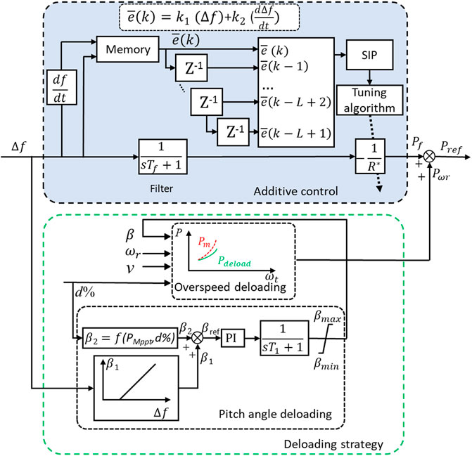
FIGURE 1. Coordinated frequency regulation system.
Wind turbine generator system
DFIG-based wind turbines are widely used on large-scale wind farms and are connected to the grid as shown in Figure 2. The wind turbine and the generator are connected by a centralized mass mechanical transmission system. The generator stator is directly connected to the network, while the rotor side is connected to the grid through back-to-back dual PWM converters (Lara et al., 2009). Both the stator and the rotor can feed the grid. In this section, the DFIG-based wind turbine is modelled.
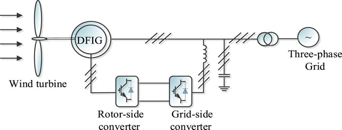
FIGURE 2. DFIG-based wind turbine connected to grid.
Wind speed model
The wind speed on a wind farm usually depends on certain factors, such as the climate, topography and landform of the local area. The Weibull distribution is generally used to describe the probability density function (PDF) of the wind speed. This is often used to reflect seasonal or annual wind speed changes over a long time scale. Moreover, a large amount of actual wind farm data is needed to represent Weibull distribution during simulation analysis. Therefore, a relatively simple combined wind speed model (Anderson et al., 1983) will be used in this work to describe the random and intermittent characteristics of wind speed in the short term.
1) Base wind
The base wind reflects the change in the average wind speed. During the operation of the wind turbine, the base wind always exists. In considering the simulation analysis of the second-level time period, the average wind speed can be taken as a constant.
where
2) Gust wind
Wind speed by nature is not always stable. A gust wind model with cosine characteristics over a period of time can be used to simulate this characteristic of wind.
where
3) Ramp wind
The following ramp wind model is used to describe the gradual change characteristics of wind speed:
where
4) Noise wind
Even if the wind speed in the actual wind farm is maintained near a certain average value, the wind speed value at each moment is irregular, so a random component can be superimposed on the average wind speed to reflect the random fluctuation in wind speed.
where
By superimposing the above four wind speed models, the following combined wind speed model is obtained to describe the wind speed changes in the short term.
Wind turbine model
The relationship between the mechanical power captured by wind turbines from wind energy and wind speed (Kundur, 1994; Lara et al., 2009) is:
where
where
Drive train model
The drive train of the DFIG wind turbine can be represented by the following two-mass model (Ela et al., 2014; Ghosh et al., 2016)
where
Converter model
In this work, the investigated DFIG uses two back-to-back PWM voltage-sourced converters to connect to the grid: the rotor-side converter
The simplified model of the main circuit of the PWM converter is shown in Figure 3.
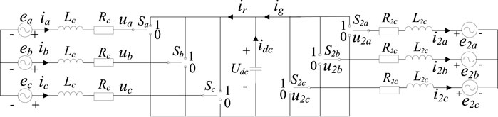
FIGURE 3. PWM converter main circuit simplified model.
Assuming that
The mathematical model of the voltage source PWM converter in the three-phase static coordinate system is
where
In order to achieve decoupling control of active and reactive power, the mathematical model of the converter in the three-phase stationary coordinate system can be simplified in the dq two-phase synchronous coordinate system through Park’s Transformation.
where
According to Eq. 12, the mathematical model of the voltage source PWM converter in the dq two-phase static coordinate system is
where
Generator model
In this section, the model of the DFIG is investigated under the same basic assumptions as Kundur (1994). The induction machine is controlled in a synchronously rotating dq-axis framer. There is no magnetic coupling between the two-phase windings. As shown in Figure 4, the stator and rotor voltage equations are
where
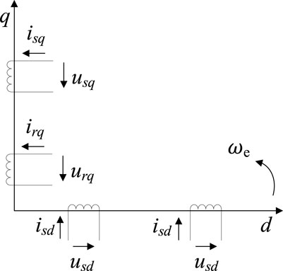
FIGURE 4. Diagram of the DFIG equivalent model in the dq coordinate system.
The stator and rotor flux linkage equations are
where
The active and reactive power on the stator side are
and the active and reactive power on the rotor side are
The electromagnetic torque equation is
where
The voltages behind the transient reactance of the stator d-axis and q-axis (Kundur, 1994) are as follows:
Aggregated model
A large-scale wind farm usually consists of several hundred units. When studying the frequency regulation strategy of the power system with wind power, the equivalent wind farm model is usually needed. First, all the units in a wind farm can be divided into several sections, according to the wind speed. Then the units in the same section can be equitably aggregated. As shown in Figure 5, the whole wind farm is divided into M sections, and each section is composed of dozens of wind turbines with the same capacity and specifications.
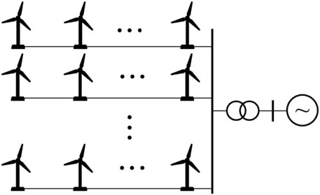
FIGURE 5. Units in a section.
n units in the same section are aggregated, the equivalent unit capacity is the sum of all wind turbine capacities of the same group:
where
The equivalent unit still maintains the same power output characteristics as a single unit. The equivalent principles of rotor impedance, excitation reactance, stator impedance, inertia time constant, damping coefficient and other parameters are as follows:
where X is the parameter that needs to be aggregated, such as the rotor resistance, the leakage inductance, and the viscous friction factor.
According to the principle of equivalence above, the aggregate model of a wind farm can be obtained, which then lays a foundation for the study of a primary frequency regulation strategy for wind farms.
A simplified model of a DFIG-based wind turbine can be used to describe the generator’s mechanical torque according to the incoming wind speed. Besides the rotor model, the drive train model, and the induction generator model, the simplified wind turbine model still includes the rotor speed controller represented by the power-speed control curve and the blade pitch angle controller.
It is difficult to build an accurate physical model on principles. However, it should be noted that a simplified model can be used to investigate the dynamic characteristics of the wind turbine generator system, or to perform small-signal stability analysis (Margaris et al., 2012; Wang et al., 2018).
Deloading strategy
The frequency of the power system depends on the balance between the power generation on the power generation side, and the load on the power consumption side. As shown in Figure 1, the coordinated control system is designed for the DFIG based-wind turbine to implement short-term frequency regulation.
A deloading strategy is needed to curtail the power output earlier, in order that the droop control can respond to an under-frequency disturbance. As shown in Figure 6, the unit will deviate from the original MPPT mode in red to the sub-optimal mode in green.
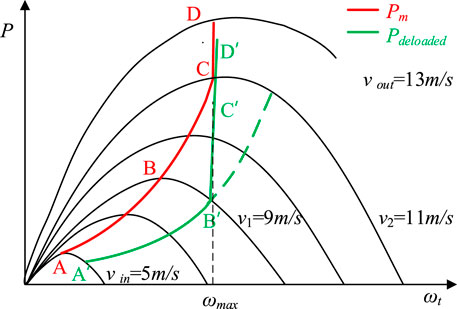
FIGURE 6. Relation of output power and speed.
Deloading at low wind speeds
It can be observed from Figure 6 that when the wind speed is greater than the cut-in wind speed
where
Deloading at middle wind speeds
It is evident from Figure 6 that the unit operates at point C when the wind speed reaches the maximum value
where
Deloading at high wind speeds
When the wind speed is
Based on the above analysis, a complete wind power PFR strategy can be obtained. As shown in Figure 6, the deloading strategy stores a certain power reserve for frequency regulation.
Additive control
Additive control plays an important role in mitigating the steady state frequency deviation before the secondary frequency response. The variable additive gain can effect a compromise between improved frequency response and reduced impacts on the structural loading (Wu Z et al., 2018). It can be observed from Figure 1 that the additive gain can be tuned online according to the ROCOF value, deloaded level, or variable wind speed conditions.
Conventional additive control
A variable speed wind turbine, controlled by a power electronic converter, can adjust the active power flexibly and controllably. As shown in Figure 1, the additional frequency regulation incorporates the inertial control and droop control. Although the droop control contributes less at the beginning of a sudden frequency drop, the rotational kinetic energy of the DFIG-based wind turbine is released and converted to electrical energy. Consequently, the power output can be increased, and the additional frequency regulation can decrease the initial ROCOF and the frequency nadir. The generator power reference
where
In order to realize the inertial response of the wind turbine, the active power reference signal
where
In addition, the wind turbine can emulate the traditional governor response for PFR. Droop control is introduced to adjust the active power output of the wind turbine according to the frequency deviation. The power reference signal related to the frequency deviation
where the droop gain
Survival information potential
The distribution of wind speed is usually non-Gaussian (Ma et al., 2010). Furthermore, there are non-linearities in DFIG-based wind turbines, and hence, it is necessary for an adaptive additive controller to decrease the randomness of the output of the additive control loop. The minimum error entropy (MEE) criterion has been applied to the design controller and filter (Yin et al., 2009; Guo et al., 2019; Li et al., 2020), which outperforms conventional criteria when dealing with non-linearities and non-Gaussian disturbances. The goal of the MEE-based control is to find a control signal to ensure the PDF of the closed-loop tracking error approach to a narrowly shaped normal distribution. In practice, the entropy is replaced by information potential (IP), because the IP can be calculated by a double summation over all samples directly. Recently, SIP was employed to design filters instead of IP (Chen et al., 2012; Zhang et al., 2016). SIP has some advantages over IP, such as shift-variant properties, easy estimation from sample data, robust measurement of uncertainty, and consistent definitions in both continuous and discrete domains.
For a random vector
where
Adaptive additive control
In this section, an adaptive additive control method is proposed for power systems with DFIG-based wind generation units. As indicated in Figure 7, the control horizon at instant
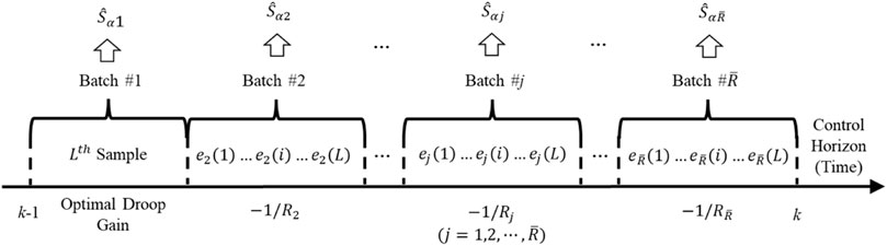
FIGURE 7. Additive control horizon.
From instant
where the optimal additive gain
In this work, the frequency deviation is scalar data case, i.e.,
where
where
Since the
The frequency deviation has played a vital role in the assessment of short-term frequency regulation performance, and so has the derivative of the frequency deviation. Hence, the frequency deviation
where
Thus, the additive gain in the
The PSO algorithm originated from the study of bird predation behavior in nature. Each particle represents a potential solution to the problem to be solved. Each particle corresponds to an objective function value. The current speed of the particle determines the direction and distance of the particle movement. The speed varies with the particle itself and other particles. The experience is dynamically adjusted to achieve the individual’s optimization in the solvable space.
In a D-dimensional search space, population
For the ith particle, the position at the time is determined by the position and velocity at the previous time:
where the velocity of the particle at time k,
where

FIGURE 8. Flowchart of PSO.
According to the above presentation, the additive control gain at instant
Step 1: Acquire the frequency deviation data within
Step 2: Compute the SIP of the hybrid term
Step 3: Calculate additive control gain
Step 4: Repeat the procedure from steps 2 and 3 for the next batch,
Step 5: Solve the optimal additive gain at the instant
Step 6: Implement the additive control gain
Simulations
In this section, some simulations are conducted to verify the feasibility of the proposed coordinated frequency regulation method. The simulation system is shown in Figure 9. The system consists of a 600 MW thermal power plant
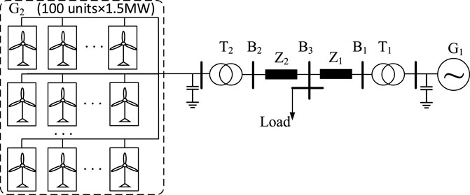
FIGURE 9. Simulation system.
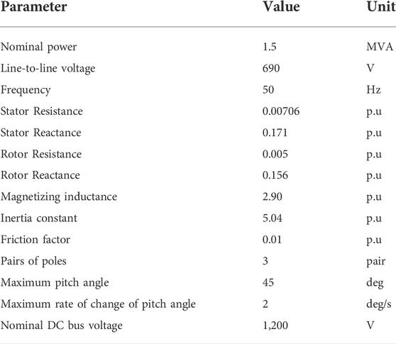
TABLE 1. Parameters of DFIG.
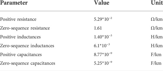
TABLE 2. Parameters of transmission line.
The collected frequency data is divided into 10 batches during two adjacent instants, i.e.,
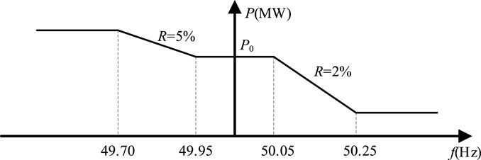
FIGURE 10. Droop curve of wind turbine.
Scenario 1: Comparison between conventional and the proposed additive control strategies.
The wind speed in the farm is simulated as shown in Figure 11. The conventional additive control utilizes fixed inertial and droop coefficients. In this work, the inertial control constant in Eq. 28 is set to
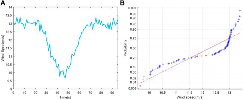
FIGURE 11. Wind speed and its probability distribution. (A) Wind speed. (B) Normal probability distribution test of wind speed.
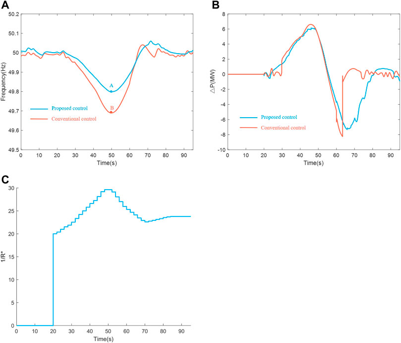
FIGURE 12. Comparison of system dynamic response. (A) Frequency response. (B) Power variations of wind power plant. (C) Optimal additive gain.
Case 1: DFIG-based wind power units do not participate in short-term frequency regulation.
It can be observed from Figure 11A that the wind speed varied slightly (0, 20 s), and DFIG-based wind power units did not participate in frequency regulation during this period. It can be seen from Figure 11B that the probability density function of wind speed was non-Gaussian.
Case 2: DFIG-based wind power units participate in short-term frequency regulation under conventional additive control.
The inertial control constant is
Case 3: DFIG-based wind power units participate in short-term frequency regulation under the proposed adaptive additive control.
When DFIG based wind power units participated in short term frequency regulation under the proposed adaptive additive control method, the frequency response is illustrated by the solid blue line in Figure 12A. Figure 12B shows the power variations of the wind power plant. The additive control gain 1/
Comparing the red-dash line with the solid blue line in Figure 12A, the proposed adaptive additive control outperforms the conventional additive control.
In order to better evaluate the proposed frequency regulation method, five performance metrics are utilized to evaluate the control quality, which include root mean square error (RMSE), mean absolute error (MAE), mean squared error (MSE), mean absolute percent error (MAPE), and standard deviation (SD).
Table 3 shows that the proposed frequency control method outperforms the traditional control method based on five performance metrics.
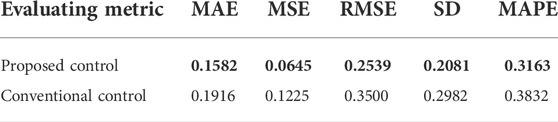
TABLE 3. Performance metrics in scenario 1.
Scenario 2: DFIG-based wind power units participate in short-term frequency regulation under the proposed additive control with different wind penetrations.
In this simulation, the investigated wind farm is composed of some DFIG-based wind power units participating in short-term frequency regulation. The number of units depends on wind penetration. The wind power capacity penetration (WPCP) is defined as
where WPCP describes the proportion of the installed wind power capacity in the area to the maximum load of the system (Wang et al., 2015). In this work, the three kinds of WPCPs investigated are 37.6, 25.0, and 18.8%, respectively. For simplicity, these DFIG-based wind power units are equitably aggregated based on the aggregated model described above.
The wind speed of the wind farm is also shown in Figure 11A. The frequency response is shown in Figure 13A; the frequency nadirs obtained by the proposed adaptive controls are 49.68 Hz (point C), 49.80 Hz (point B), and 49.86 Hz (point A), with 37.6, 25.0, and 18.8% WPCPs respectively. The frequency nadir decreases with increasing WPCPs. The power variations of the wind power plant are shown in Figure 13B. The proposed adaptive additive controller is suitable for different WPCPs. Figure 13C demonstrates variations in the proposed adaptive additive coefficients during the transient period. The time-variable additive control coefficients with three WPCPs are shown as Figure 13C.
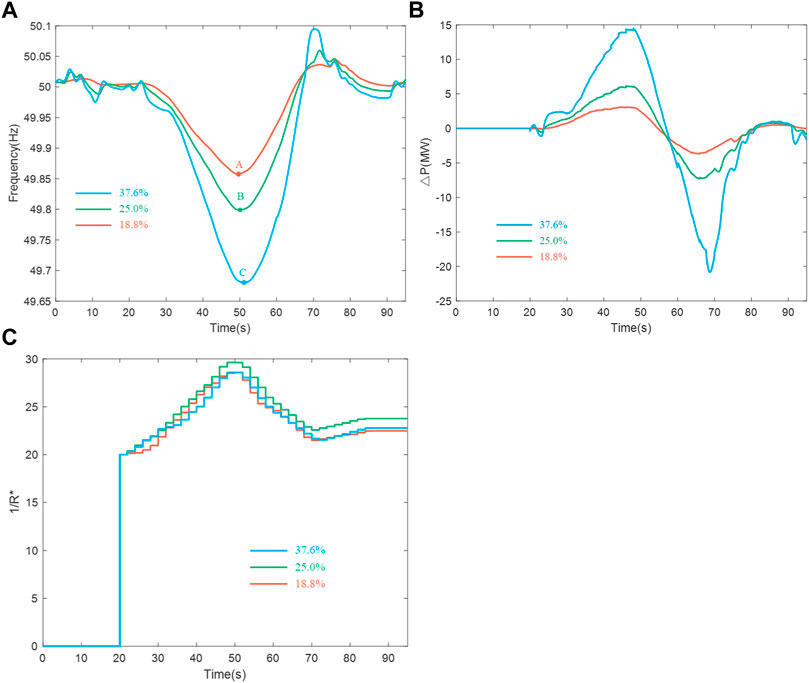
FIGURE 13. SFR in scenario 2. (A) Frequency response. (B) Power variations of wind power plant. (C) Additive control coefficients.
It can be observed from Table 4 that the performance metrics increase with increasing WPCP. The proposed method can deal with frequency regulation of a power system with high wind power capacity penetration.
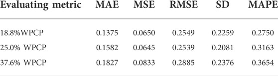
TABLE 4. Performance metrics in scenario 2.
Conclusion
This paper presents an overall frequency regulation scheme for DFIG-based wind power units participating in short-term frequency regulation. A data-driven additive controller is cast into a stochastic framework. Since there are non-Gaussian disturbances in wind power systems, the SIP performance index is employed to update the additive control law. Some batches are divided during adjacent instants, in which the optimal additive control coefficient can be adaptively updated in each batch by using PSO technique. The optimal additive control signal between adjacent instants can then be obtained by inputting all the additive control coefficients to an arithmetic mean filter. The effectiveness of the proposed approach, in comparison with traditional additive control strategies, is confirmed by simulation results.
Due to the randomness of wind speed on actual wind farms, and the communication delay between dispatch centers and wind farms, it will be a challenge to extend this scheme to coordinate control of multiple wind farms. The coordinate control of multiple wind farms will thus be considered in the future to improve frequency support capability. In addition, the proposed data-driven method can be extended to any processes with non-linearities and non-Gaussian noise distributions.
Data availability statement
The original contributions presented in the study are included in the article/supplementary materials, and further inquiries can be directed to the corresponding author.
Author contributions
Conceptualization, RS and JZ; methodology, RS and QM; resources, GZ, LW, and BL; software, RS and QM; writing—original draft, RS; writing—review and editing, QM and JZ. All authors have read and agreed to the published version of the manuscript.
Funding
This work was supported by the National Key R&D Program of China, No. 2019YFB1505400.
Acknowledgments
The authors would like to thank the reviewers for their valuable comments.
Conflict of interest
RS was employed by Chn Energy United Power Technology Company Ltd. GZ, LW, and BL were employed by State Grid Liaoning Electric Power Supply Co. Ltd.
The remaining authors declare that the research was conducted in the absence of any commercial or financial relationships that could be construed as a potential conflict of interest.
Publisher’s note
All claims expressed in this article are solely those of the authors and do not necessarily represent those of their affiliated organizations, or those of the publisher, the editors and the reviewers. Any product that may be evaluated in this article, or claim that may be made by its manufacturer, is not guaranteed or endorsed by the publisher.
References
Anderson, P., and Bose, A. (1983). Stability simulation of wind turbine systems. IEEE Trans. Power Apparatus Syst. 102, 3791–3795. doi:10.1109/tpas.1983.317873
Bao, W., Wu, Q., Ding, L., Huang, S., and Terzija, V. (2021). A Hierarchical inertial control scheme for multiple wind farms with besss based on ADMM. IEEE Trans. Sustain. Energy 12, 751–760. doi:10.1109/tste.2020.2995101
Chen, B., Zhu, P., and Principe, J. C. (2012). Survival information potential: A new criterion for adaptive system training. IEEE Trans. Signal Process. 60, 1184–1194. doi:10.1109/tsp.2011.2178406
Datta, U., Shi, J., and Kalam, A. (2019). Primary frequency control of a microgrid with integrated dynamic sectional droop and fuzzy based pitch angle control. Int. J. Electr. Power & Energy Syst. 111, 248–259. doi:10.1016/j.ijepes.2019.04.001
de Almeida, R. G., and Pecas Lopes, J. A. (2007). Participation of doubly fed induction wind generators in system frequency regulation. IEEE Trans. Power Syst. 22, 944–950. doi:10.1109/tpwrs.2007.901096
Dziwinski, P., and Bartczuk, L. (2020). A new hybrid particle swarm optimization and genetic algorithm method controlled by fuzzy logic. IEEE Trans. Fuzzy Syst. 28, 1140–1154. doi:10.1109/tfuzz.2019.2957263
Ekanayake, J., and Jenkins, N. (2004). Comparison of the response of doubly fed and fixed-speed induction generator wind turbines to changes in network frequency. IEEE Trans. Energy Convers. 19, 800–802. doi:10.1109/tec.2004.827712
Ela, E., Gevorgian, V., Fleming, P., Zhang, Y. C., Singh, M., Muljadi, E., et al. (2014). Active power controls from wind power: Bridging the gaps. Golden, CO, USA: National Renewable Energy Laboratory. NREL/TP-5D00-60574.
Garmroodi, M., Verbic, G., and Hill, D. J. (2018). Frequency support from wind turbine generators with a time-variable droop characteristic. IEEE Trans. Sustain. Energy 9, 676–684. doi:10.1109/tste.2017.2754522
Ghosh, S., Kamalasadan, S., Senroy, N., and Enslin, J. (2016). Doubly fed induction generator (DFIG)-based wind farm control framework for primary frequency and inertial response application. IEEE Trans. Power Syst. 31, 1861–1871. doi:10.1109/tpwrs.2015.2438861
Guo, L., Yi, Y., Yin, L., and Wang, H. (2019). Modeling analysis and control theory of non-Gaussian random distribution system. Beijing: Science Press.
Jia, J., Yan, Z., Peng, X., and An, X. (2020). A new distribution for modeling the wind speed data in inner Mongolia of China. Renew. Energy 162, 1979–1991. doi:10.1016/j.renene.2020.10.019
Kang, M., Muljadi, E., Hur, K., and Kang, Y. C. (2016). Stable adaptive inertial control of a doubly-fed induction generator. IEEE Trans. Smart Grid 7, 2971–2979. doi:10.1109/tsg.2016.2559506
Kim, J., Muljadi, E., Gevorgian, V., and Hoke, A. F. (2019a). Dynamic capabilities of an energy storage-embedded DFIG system. IEEE Trans. Ind. Appl. 55, 4124–4134. doi:10.1109/tia.2019.2904932
Kim, J., Muljadi, E., Gevorgian, V., Mohanpurkar, M., Luo, Y., Hovsapian, R., et al. (2019b). Capability-coordinated frequency control scheme of a virtual power plant with renewable energy sources. IET Gener. Transm. Distrib. 13, 3642–3648. doi:10.1049/iet-gtd.2018.5828
Lara, O., Jenkins, N., Ekanayake, J., Cartwright, P., and Hughes, M. (2009). Wind energy generation: Modelling and control. Hoboken John: Wiley & Sons.
Lee, J., Jang, G., Muljadi, E., Blaabjerg, F., Chen, Z., and Cheol Kang, Y. (2016a). Stable short-term frequency support using adaptive gains for a DFIG-Based wind power plant. IEEE Trans. Energy Convers. 31, 1068–1079. doi:10.1109/tec.2016.2532366
Lee, J., Muljadi, E., Sorensen, P., and Kang, Y. C. (2016b). Releasable kinetic energy-based inertial control of a DFIG wind power plant. IEEE Trans. Sustain. Energy 7, 279–288. doi:10.1109/tste.2015.2493165
Li, Y., Xu, Z., Zhang, J., and Wong, K. P. (2018). Variable gain control scheme of DFIG-based wind farm for over-frequency support. Renew. Energy 120, 379–391. doi:10.1016/j.renene.2017.11.055
Li, Z., Xing, L., and Chen, B. (2020). Adaptive filtering with quantized minimum error entropy criterion. Signal Process. 172, 107534. doi:10.1016/j.sigpro.2020.107534
Ma, H. T., and Chowdhury, B. H. (2010). Working towards frequency regulation with wind plants: Combined control approaches. IET Renew. Power Gener. 4, 308. doi:10.1049/iet-rpg.2009.0100
Margaris, I. D., Papathanassiou, S. A., Hatziargyriou, N. D., Hansen, A. D., and Sorensen, P. (2012). Frequency control in autonomous power systems with high wind power penetration. IEEE Trans. Sustain. Energy 3, 189–199. doi:10.1109/tste.2011.2174660
Morren, J., Pierik, J., and de Haan, S. W. H. (2006). Inertial response of variable speed wind turbines. Electr. Power Syst. Res. 76, 980–987. doi:10.1016/j.epsr.2005.12.002
Northeast Regulatory Bureau of National Energy Administration (2019). Grid code for auxiliary service management of grid connected power plants in Northeast China.
Pourbeik, P. (2013). Proposed changes to the WECC WT4 generic model for type 4 wind turbine generators. Salt Lake: The Electric Power Research Institute.
Vidyanandan, K. V., and Senroy, N. (2013). Primary frequency regulation by deloaded wind turbines using variable droop. IEEE Trans. Power Syst. 28, 837–846. doi:10.1109/tpwrs.2012.2208233
Wang, H., Liu, Y., Zhou, B., Voropai, N., Cao, G., Jia, Y., et al. (2020). Advanced adaptive frequency support scheme for DFIG under cyber uncertainty. Renew. Energy 161, 98–109. doi:10.1016/j.renene.2020.06.085
Wang, P., Zhang, Z., Huang, Q., Wang, N., Zhang, X., and Lee, W.-J. (2018). Improved wind farm aggregated modeling method for large-scale power system stability studies. IEEE Trans. Power Syst. 33, 6332–6342. doi:10.1109/tpwrs.2018.2828411
Wang, Y., Zhu, X., and Zhao, S. (2015). Modeling and simulation of wind power system. Beijing: China Water Conservancy and Hydropower Press.
Wu, Y.-K., Yang, W.-H., Hu, Y.-L., and Dzung, P. Q. (2019). Frequency regulation at a wind farm using time-varying inertia and droop controls. IEEE Trans. Ind. Appl. 55, 213–224. doi:10.1109/tia.2018.2868644
Wu, Z., Gao, W., Gao, T., Yan, W., Zhang, H., Yan, S., et al. (2018). State-of-the-art review on frequency response of wind power plants in power systems. J. Mod. Power Syst. Clean. Energy 6, 1–16. doi:10.1007/s40565-017-0315-y
Yang, D., Jin, Z., Zheng, T., and Jin, E. (2022). An adaptive droop control strategy with smooth rotor speed recovery capability for type III wind turbine generators. Int. J. Electr. Power & Energy Syst. 135, 107532. doi:10.1016/j.ijepes.2021.107532
Yang, D., Kim, J., Kang, Y. C., Muljadi, E., Zhang, N., Hong, J., et al. (2018). Temporary frequency support of a dfig for high wind power penetration. IEEE Trans. Power Syst. 33, 3428–3437. doi:10.1109/tpwrs.2018.2810841
Yin, L., and Guo, L. (2009). Fault isolation for multivariate nonlinear non-Gaussian systems using generalized entropy optimization principle. Automatica 45, 2612–2619. doi:10.1016/j.automatica.2009.07.023
Zertek, A., Verbic, G., and Pantos, M. (2012). A novel strategy for variable-speed wind turbines’ participation in primary frequency control. IEEE Trans. Sustain. Energy 3, 791–799. doi:10.1109/tste.2012.2199773
Zhang, J., Kuai, Y., Ren, M., Luo, Z., and Lin, M. (2016). Event-triggered distributed filtering for non-Gaussian systems over wireless sensor networks using survival information potential criterion. IET Control Theory &. Appl. 10, 1524–1530. doi:10.1049/iet-cta.2015.1014
Zhang, J., Shan, R., Xu, F., Hu, B., Zhou, G., Hou, G., et al. (2020). “Coordinated dispatching and frequency control strategy of power systems with large scale wind power penetration,” in 2020 Chinese Automation Congress (CAC) (Shanghai, China: IEEE), 6956–6961. doi:10.1109/CAC51589.2020.9327417
Keywords: wind power systems, primary frequency regulation, inertial control, particle swarm optimization, survival information potential
Citation: Zhang J, Ma Q, Shan R, Zhou G, Wang L, Li B and Wang Y (2022) Short-term frequency regulation of power systems based on DFIG wind generation. Front. Energy Res. 10:948185. doi: 10.3389/fenrg.2022.948185
Received: 19 May 2022; Accepted: 11 July 2022;
Published: 30 August 2022.
Edited by:
Leo Raju, SSN College of Engineering, IndiaReviewed by:
Dejian Yang, Northeast Electric Power University, ChinaSina Ardabili, University of Mohaghegh Ardabili, Iran
Copyright © 2022 Zhang, Ma, Shan, Zhou, Wang, Li and Wang. This is an open-access article distributed under the terms of the Creative Commons Attribution License (CC BY). The use, distribution or reproduction in other forums is permitted, provided the original author(s) and the copyright owner(s) are credited and that the original publication in this journal is cited, in accordance with accepted academic practice. No use, distribution or reproduction is permitted which does not comply with these terms.
*Correspondence: Jianhua Zhang, empoQG5jZXB1LmVkdS5jbg==