- 1College of Power and Energy Engineering, Harbin Engineering University, Harbin, China
- 2Dongfang Turbine Co., Ltd., Deyang, China
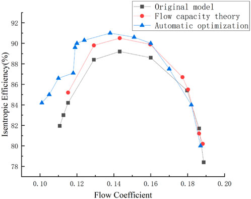
The present paper focuses on the optimization of large-flow coefficient centrifugal compressors, utilizing a mature centrifugal compressor impeller with a flow coefficient of 0.16 under design point condition in engineering as the research subject. Due to the more complex flow mechanism and more design parameters in the impeller with large flow coefficient, the traditional artificial optimization method is insufficient. In present paper, the impeller with a large flow coefficient is optimized using the concept of combining physical principles and artificial intelligence tools. Firstly, the impeller underwent a redesign based on the theory of maximum flow capacity, with the aim of reducing the Mach number at the impeller inlet to enhance the compressor’s performance. And the efficiency of the impeller at the design point has been increased from 88.6% to 89.9%. In order to further improve the performance of the impeller, an optimization algorithm grounded in gradient variation was employed to facilitate the automatic compressor optimization, and the flow losses at the impeller’s top under low-flow conditions has been mitigated. The results of three-dimensional numerical simulation showed that the operating range of the new impeller is 7% wider than that of the original impeller.
1 Introduction
Since the late 19th century, centrifugal compressors have been widely utilized in various fields such as petrochemical, energy, power generation, and marine transportation due to their high single-stage pressure ratio, compact structure, and broad operating range stability (Bruce et al., 1998; Krain, 2005). Against the backdrop of the current “carbon peaking and carbon neutrality goals,” the application scope of centrifugal compressors has expanded, accompanied by increased demands for their aerodynamic performance and stable operating ranges. In the centrifugal compressors in the fields of petrochemical industry and compressed gas energy storage, there are lots of stages in one cylinder and the pressure ratio is large (Lüdtke, 2004). As the gas is compressed stage by stage, the volumetric flow rate at each stage gradually decreases. In order to prevent the volume flow of the final stage from being too small, causing a large decrease in efficiency, the first stage is usually designed with a large flow coefficient. For example, centrifugal compressors in the field of compressed gas energy storage have a first-stage flow coefficient of more than 0.15 (Garvey and Pim, 2016). However, the understanding of the internal flow mechanisms of large-flow coefficient centrifugal compressors remains insufficient. These compressors’ impellers are characterized by long blades, intricate internal flow patterns, numerous design parameters with complex interdependencies, and non-dimensional aerodynamic structural parameters that often surpass the existing impeller’s operating range (Krain, 1984). Moreover, due to the larger blade heights in large-flow coefficient compressors, significant variations occur in the impeller’s circumferential and meridional velocity distributions, resulting in substantial changes in the inlet flow angles along the blade height direction and complex flow structures within the passage, thereby posing challenges in impeller design and optimization.
For large-flow coefficient compressors, major companies like Siemens with their VK gear-assembled and Man Turbo with cantilever plus dual-supported isothermal centrifugal compressor products, typically maintain a first-stage flow coefficient of around 0.16. Meanwhile, companies like GE employ mixed-flow impeller designs to meet even higher flow coefficient requirements (Denton, 1993; Rubino et al., 2024). Currently, the literature predominantly focuses on single-stage or specific component studies for large-flow coefficient compressors, with limited comprehensive research dedicated specifically to large-flow coefficient centrifugal compressors. Regarding the flow characteristics of turbomachinery, Denton (1993) conducted a detailed review on the loss mechanisms in turbomachinery. The primary sources of losses in turbomachinery have been categorized as profile losses, endwall losses, and clearance losses, with their magnitudes roughly comparable and exhibiting interactions between each other. Dean and Senoo (1960) and Eckardt (1975) experimentally found that the flow rate from the impeller into the diffuser was not axially symmetrical, and proposed a simplified model theory to describe this phenomenon. Inoue and Cumpsty (1984) and Rohne and Banzhaf (1991) quantitatively measured the inhomogeneity of the flow rate between the impeller and the diffuser. And through the relationship between its inhomogeneity and flow coefficient, the classical jet-wake theory is corrected. Subsequently, Pinarbasi (2008) and Kang et al. (2010) performed a series of experiments to compare the flow mechanism of jet-wake flow in vaneless diffuser vane diffuser. These findings provide theoretical insights for the design of high-performance impellers. Krain and Hoffmann (2007) provided the thinking of centrifugal impeller design with splitter blades, which improved the performance of the compressor. Veress et al. (2004) employed Computational Fluid Dynamics (CFD) methods to analyze the primary flow characteristics and flow mechanisms inside stationary components such as bends and diffusers, proposing a design optimization method for channels. Baljé (1964) investigated the internal flow characteristics and performance variations of compressor impellers at different Reynolds numbers. The results indicate that as Reynolds number decreases, the efficiency, flow capacity, and surge margin of centrifugal compressors decrease, affecting the blade surface loading distribution and reducing the impeller’s operability (Baljé, 1964; Guelich, 2003). Yagi et al. (2015) modified the traditional single-row blade configuration of the diffuser by incorporating splitter blades, enhancing the flow field and improving the performance of the diffuser.
Due to inadequate understanding of flow mechanisms, traditional trial-and-error methods often require multiple iterative cycles, leading to long design cycles and difficulties in obtaining globally optimal solutions. Moreover, this approach heavily relies on the designer’s experience. In recent years, optimization methods based on numerical simulations have been widely employed for the optimization of various components of centrifugal compressors. Overall, the optimization methods for centrifugal compressors have evolved from single-objective optimization to multi-objective optimization, and from aerodynamic optimization to multidisciplinary optimization encompassing both aerodynamics and structural considerations. Furthermore, optimization has progressed from single-point optimization to multi-point or even full-operating-range optimization. For example, Demeulenaere et al. (2015) utilized a weighted objective function method to optimize multiple aerodynamic performance indicators of centrifugal impellers for turbocharger applications. An et al. (2016) conducted multi-objective optimization of low-speed centrifugal pump design conditions using a genetic algorithm, obtaining the Pareto optimal solution set for two objective functions. Kang and Kim (2016) implemented multi-objective optimization of centrifugal impellers based on response surface models. Long and Wu (2014) combined a genetic algorithm with the Hooke-Jeeves method to develop a globally applicable mixed optimization algorithm for systems with constraints. Sevastyanov (2010) proposed a hybrid optimization algorithm using a dynamic response surface model to evaluate gradient values. Wang et al. (2018) developed a gradient-based multi-objective genetic algorithm, successfully applied to optimize wind turbine blade designs. Kim et al. (2009) optimized the impeller of a centrifugal compressor with splitter blades using radial basis function neural networks and multi-objective evolutionary algorithms. They selected control points on the hub and shroud of the meridional passage as optimization variables, with efficiency and pressure ratio as objective functions, resulting in two optimized designs with efficiency improvements of 0.65% and 0.19%, and pressure ratio improvements of 0.86% and 1.4%, respectively. Ibaraki et al. (2015) found that after improving impeller designs using computational fluid dynamics (CFD) and experimental methods, further improvements in impeller aerodynamic performance were difficult to achieve using such methods alone. Therefore, they applied a genetic algorithm and artificial neural networks to optimize centrifugal compressor impeller designs, presenting two optimized design solutions that significantly improved impeller aerodynamic performance (Lin et al., 2012). Zuo et al. put forward a new multi-objective algorithm combining RSM (response surface method) and NSGA-II (non-dominated sorting genetic algorithm), and achieved excellent results in the design of proton exchange membrane fuel cells. And, the algorithm also provides important inspiration for the current work (Li et al., 2022; Chen et al., 2023; Zuo et al., 2023; Zuo et al., 2024).
However, the majority of existing studies treat compressor optimization as a black-box problem, disregarding the mechanism of the internal flow field. They solely focus on the mapping relationship between geometric parameters and macroscopic aerodynamic performance, treating it as a purely data-driven design method. This approach is indiscriminately applied to any other engineering optimization problem. Consequently, this determines that optimization design methods may not necessarily yield excellent design solutions and struggle to overcome the bottleneck of multi-objective constraints, leading to optimization limitations.
Therefore, this study addresses the significant challenge of directly optimizing impellers for large-flow coefficient centrifugal compressors. Firstly, a design methodology based on maximum flow capacity is employed to establish rational design parameters from a physical standpoint. Additionally, by delving into the mechanism of internal flow, the research extensively investigates the nonlinear coupling and constraint laws among compressor geometry, flow dynamics, and aerodynamic parameters, identifying key variables. Through single-factor analysis, the range of values for these key variables have been determined, thereby defining a rational design space. Finally, a hybrid gradient variation optimization approach is employed for the optimization design.
2 Description of models and methods
2.1 Introduction to the original model
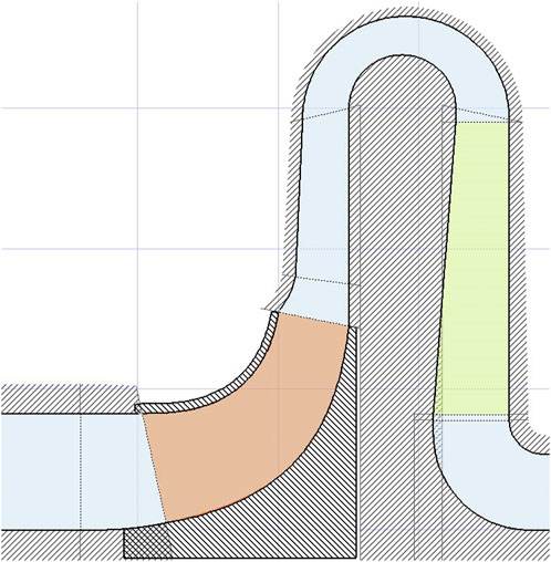
The meridional projection of the compressor stage model is illustrated in Figure 1. This model consists of an inlet section, impeller, vaneless diffuser, bend, blade return channel, and outlet section.
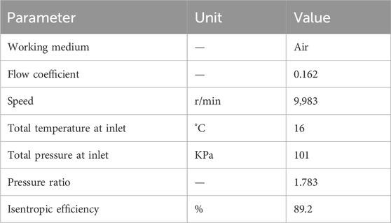
The relevant parameters and boundary conditions of this model are detailed in Table 1. The parameters and boundary conditions of the model are shown in Table 1.
Where the flow coefficient is a dimensionless parameter describing the compressor’s flow capacity, defined by the Equation 1:
Isentropic efficiency refers to the ratio of the isentropic compression energy
2.2 Numerical methodology
The impeller model was subjected to three-dimensional numerical simulations using CFX software. The original geometric data was converted into CFX standard geometry files and imported into Turbo-Grid for grid generation. Mainly, an OH-type structured grid was employed, with an O-type grid used near the blades and an H-type grid used in other regions, supplemented by I-type and J-type grids for connection. The grid is depicted in Figure 2.
The internal flow of centrifugal compressors adheres to the principles of conservation of mass, momentum, and energy, governed by the continuity equation, momentum equation, and energy equation, respectively. The commercial software CFX was used for the numerical calculation. And it has been widely used in the field of rotating machinery because of its high accuracy (Yang et al., 2023). The k-omega SST turbulence model is utilized to account for the turbulent characteristics of the compressor’s internal flow field. This model demonstrates good simulation accuracy for phenomena such as adverse pressure gradients and flow separation. The boundary conditions are set as follows: total temperature and total pressure are specified at the inlet, while mass flow rate is specified at the outlet. The dynamic-stationary interface adopts the “stage” method for data transfer. It processes the flow parameters upstream and downstream of the dynamic-stationary interface with circumferential averaging before transmitting the data. This approach ensures strict conservation of momentum and energy and is commonly used in single-channel compressor calculations, particularly when there is a significant disparity in the cross-sectional area between upstream and downstream components, offering better computational accuracy. The settings of walls satisfy the adiabatic no-slip condition. Convergence criteria are set such that residuals reach 10–6 (or efficiency/pressure ratio curves remain unchanged or exhibit periodic fluctuations with increasing iteration steps), and the relative error in mass flow rate at the inlet and outlet is less than 10–3. The rationality of the above-mentioned setup of turbulence model and grid has been verified. (Yang et al., 2024).
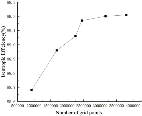
By varying the number of circumferential grid points, total grid count, and growth rate, four different grid configurations were obtained, as shown in the table below. The variation of design point efficiency with the number of grids is depicted in Figure 3. It can be seen that for this model, when the grid count reaches 2.45 million, the design point efficiency remains relatively constant with increasing grid count. Therefore, in subsequent flow field simulations, it is necessary to ensure that the grid count for each optimization scheme can’t lower than the value mentioned above.
2.3 Parameterization methodology
Large-flow coefficient centrifugal compressors have complex structures and numerous design parameters. Additionally, intricate flow mechanisms within them result in complex coupling relationships among various key parameters. In engineering practice, a common approach is to employ three-dimensional parametric modeling methods. These methods aim to describe complex three-dimensional models using only a small number of geometric parameters.
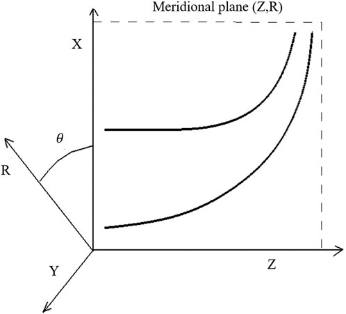
For the centrifugal compressor model described above, its parametric modeling primarily involves meridional line parametrization, mid-curve parametrization of blades, stacking laws for blade thickness, and stacking laws for blade curvature. Figure 4 depicts the coordinate system for parametric modeling of the centrifugal compressor, where xyz represents the Cartesian coordinate system, with the Z-axis as the rotational axis, and θ as the azimuth angle. The (z, R) plane denotes the meridional plane, while the (z, x) and (z, y) planes represent specific meridional planes. The meridional lines shown in the figure are projections within the (z, x) plane.
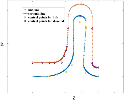
The meridian curve can be directly defined as a parameterized curve in a two-dimensional plane, and then rotated along the circumferential direction for a complete revolution. The meridian curve is performed in the (Z, R) plane, including the hub and the shroud curve. By a series of control points and based on the cubic spline interpolation algorithm, the hub curve and the rim curve of each component are constructed separately. The combined meridian curves are shown in Figure 5.
The parametric modeling of the blade is achieved by constructing the mid-camber line and then specifying the blade thickness at various locations along the blade’s chord. The mid-camber line is parameterized within the
Where dz and dR respectively represent the infinitesimal elements of (Z, R) coordinates.
The mid-camber line is constructed using the NURBS method, and the mid-camber line shape is as shown in Figure 6.
Subsequently, the determination of the blade thickness stacking pattern ensues. Blade thickness stacking refers to the process of layering thickness on both sides of the mid-camber line to achieve a complete blade profile. Consequently, the stacking of blade thickness is conducted within the
Finally, the determination of the chordwise stacking pattern of the blade is established. For centrifugal compressors with large flow coefficient, the blades exhibit a complex three-dimensional structure. The chordwise stacking of such twisted blades comprises two aspects: the stacking along the leading edge midline and the stacking along the axial direction of the blade. The stacking along the leading edge midline is controlled using Bézier curves, as depicted in Figure 8A. The circumferential stacking is also executed using Bézier curves, with the hub as the reference, allowing for variation in the blade’s sweep angle in the axial direction, which is illustrated in Figure 8B.
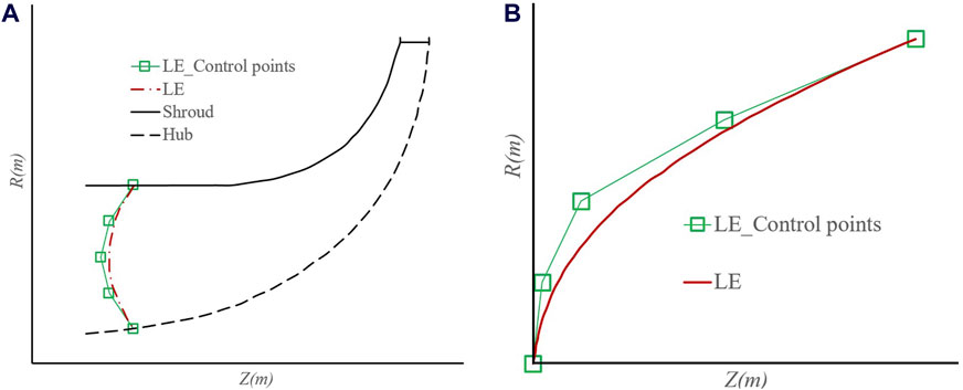
Figure 8. The stacking method of the blade. (A) The stacking along the leading edge midline. (B) The stacking along the axial direction.
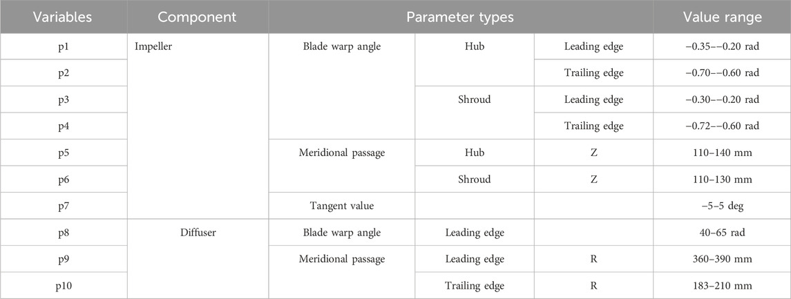
By employing the parameterization approach outlined earlier, intricate compressor models can be effectively governed by a finite set of parameters. Drawing from empirical insights, ten critical parameters have been identified for optimization, encompassing aspects such as the leading and trailing edge angles of impeller blades at the blade tip level within centrifugal compressor elemental constructs. The determination of parameter ranges is grounded in empirical knowledge, as delineated in Table 2.
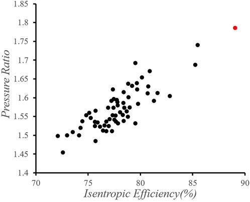
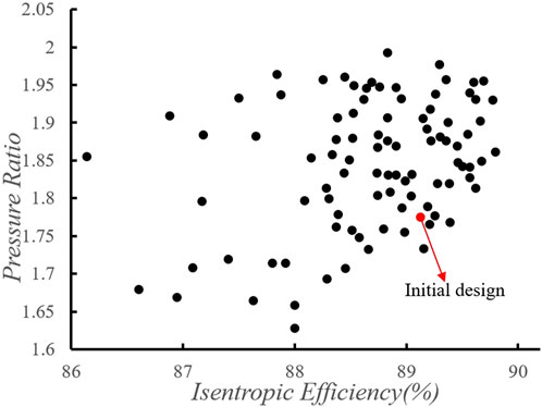
As each of the aforementioned parameters undergoes variation, a plethora of three-dimensional design configurations emerges. To circumvent iterative calls to the CFD solver, a Latin hypercube sampling technique is adopted, yielding 150 samples for subsequent three-dimensional computational assessments. The performance metrics of each sample point are delineated in Figure 9.
Figure 9 presents the performance parameters of the samples, where the horizontal axis represents the isentropic efficiency and the vertical axis represents the pressure ratio. Each point denotes a distinct sample, with the red point denoting the original design. It is evident from the figure that the sample points predominantly align along the diagonal, indicating a positive correlation between efficiency and pressure ratio. This reaffirms the reliability of numerical simulation methods. However, regrettably, the computational results of the sample points all fall below and to the left of the original design. Consequently, employing a direct optimization approach fails to yield design solutions superior to the original design.
In summary, the section commenced with an exposition on a mature compressor design tailored for a high flow coefficient within engineering contexts. Subsequent to this, an elaborate presentation ensued on the intricacies of three-dimensional numerical simulation methodologies. Finally, the discourse delved into the utilization of a three-dimensional parameterization approach for modeling, coupled with conventional optimization strategies. The outcomes underscored a pivotal observation: conventional empirical optimization methods are rendered inadequate for high-performance mature impeller models characterized by a high flow coefficient.
3 Secondary design methods
3.1 The maximum flow capacity
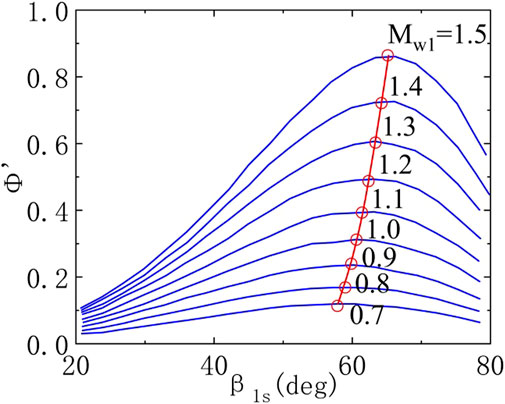
In light of the inadequacy of traditional empirical optimization techniques, in accordance with Michael Casey’s theory, for centrifugal compressor models characterized by certain flow coefficients, the flow coefficient defined by Equation 4, and the inlet shroud relative flow angle defined by Equation 5:
Figure 10 depicts the functional relationship between the flow coefficient
Drawing upon the aforementioned theory and incorporating the present inlet and outlet boundary conditions of the impeller, a redesign is envisaged.
1) Given design objectives for the centrifugal impeller, including isentropic efficiency
2) Setting the initial Enthalpy rise coefficient
3) Calculate the relative axial airflow angle at the inlet shroud of the centrifugal impeller by Equation 6:
The iterative computation result is:
4) Calculate the relative Mach number at the inlet shroud of the centrifugal impeller by Equation 7:
The iterative computation result is:
5) Calculate the Enthalpy rise coefficient by Equation 8:
The iterative computation result is:
6) Determine if the relative error between the Enthalpy rise coefficient
7) Calculating the diameter of the inlet shroud of the centrifugal impeller
8) Calculating the width of the outlet shroud of the centrifugal impeller
9) Following steps 1 through 8, dimensionless design outcomes have been derived, delineating a spectrum of design propositions. To render these into concrete design solutions, further dimensional parameters are requisite, encompassing centrifugal impeller inlet specifications: inlet total temperature and inlet total pressure
10) Calculating the diameter of the hub of the centrifugal impeller
11) Calculating the centrifugal impeller inlet hub diameter
12) Calculating centrifugal impeller outlet width
13) Calculating the centrifugal impeller outlet peripheral speed
14) Calculating the design speed of centrifugal impeller
15) Calculating inlet density
16) Calculating design mass flow
17) Calculating the relative axial airflow angle of the centrifugal impeller inlet hub
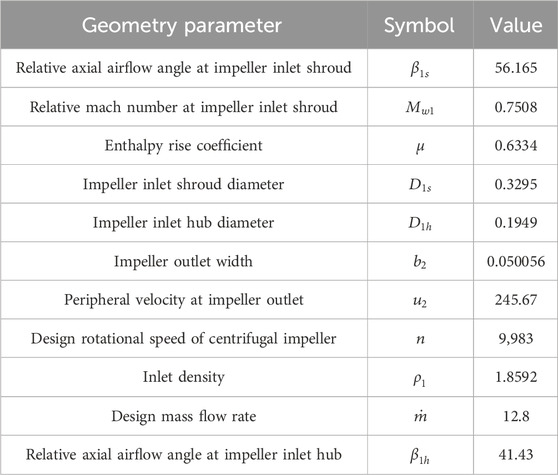
At this juncture, the aerodynamic and geometric parameters requisite for centrifugal impeller design have been computed, as delineated in Table 3.
3.2 The automatic optimization gradient descent algorithm
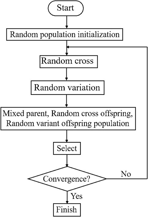
Drawing from the theory of maximum flow capacity, which has yielded promising outcomes at the physical level, we now embark on a data-driven approach to pursue optimal solutions, using the aforementioned scheme as a prototype. Due to the high-dimensional, nonlinear, and globally multi-objective nature of optimizing internal flow parameters in centrifugal compressors, where objective functions are interlinked and constrained, traditional empirical optimization methods and single-parameter analysis approaches struggle to ensure harmonization among various parameters, making it challenging to attain solutions that simultaneously fulfill multiple optimization goals. Hence, algorithmic automatic optimization offers an effective approach. Among these, genetic algorithms are the most widely applied stochastic optimization methods, evolving from single-objective optimization to multi-objective optimization. Among them, the most prominent in multi-objective optimization for turbomachinery is the second-generation Non-dominated Sorting Genetic Algorithm (NSGA-II). Figure 11 illustrates the flowchart of the NSGA-II algorithm.
NSGA-II fundamentally belongs to a pure stochastic algorithm category, renowned for its strong global search capability, theoretically capable of converging to the global optimum after a sufficient number of iterations. However, as it approaches the optimal solution, where the differences among individuals become minimal, the convergence speed of the NSGA-II algorithm tends to be slow.
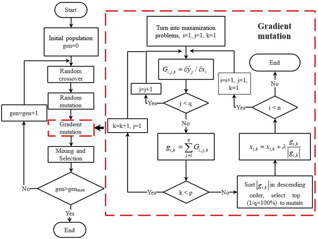
In order to accelerate convergence speed and mitigate the propensity for gradient-based optimization algorithms to become ensnared in local optima, this study introduces a gradient mutation operation integrated with the NSGA-II genetic algorithm, thereby formulating the Gradient Mutation Hybrid (GMH) optimization algorithm. The diagram depicts the flowchart of the GMH optimization algorithm, which differs from the NSGA-II algorithm in two aspects: 1) The addition of a gradient mutation operation following random mutation; 2) The blending of offspring obtained from gradient mutation with the parent population, offspring from random crossover, and offspring from random mutation, followed by selection to form the new parent population.
The essence of algorithmic enhancement lies in the gradient mutation operation, which systematically mutates in the direction of gradient descent with a specified step size, thus accelerating the convergence process. Furthermore, random crossover and mutation prevent the algorithm from converging to local optima. Consequently, the GMH optimization algorithm dramatically boosts optimization speed while preserving diversity in the optimal solution set. Figure 12 illustrates the process flow of the gradient mutation algorithm.
Using the above method to optimize the impeller, and the performances of 150 sample points are shown in the Figure 13. Select the sample with the best performance from 150 sample points for variable working condition calculation.
The variable working condition curve of the optimized impeller is shown in the following Figure 14.
4 Discussion of flow field details
The optimization scheme significantly widens the stable operating range on the low-flow side. In this section, we delve into the reasons behind the strengthened stability on the low-flow side by contrasting the flow fields with those of the original design. Leveraging Stenning’s (Ibaraki et al., 2015) flutter criterion and complemented by the velocity distribution map at 99% blade height depicted in Figure 15 for the original design, we provide further insights. According to Stenning’s flutter criterion and in reference to the velocity distribution map at 99% blade height depicted in Figure 15 for the original design, it is observable that at the point of 75% design mass flow rate point, the original design aligns with the highest pressure ratio point. At this juncture, the flow state at this section is favorable, with localized flow separation occurring in the midstream region. Nevertheless, downstream flow remains aligned with the blade path. Localized separation of flow creates a low-velocity region, which develops downstream into the wake region along the red arrow. When the flow rate decreases to 72% design point, severe separation occurs at the leading edge of the blades. This separated flow extends all the way to the impeller outlet, forming a large area of low velocity that severely obstructs the flow passage. Localized separation of flow creates a low-velocity region, which develops downstream into the wake region along the red arrow. Figure 16 shows the corresponding three-dimensional vector diagram. According to Figure 16, it can be seen the low-speed region of the unstable condition is large-scale recirculation vortex. It means that the backflow at the trailing edge of the blade has developed to the leading edge position, And the compressor has become unstable.
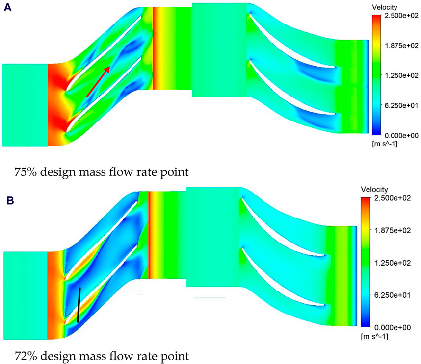
Figure 15. Velocity contour of 99% blade height for the initial design. (A) 75% design mass flow rate point. (B) 72% design mass flow rate point.
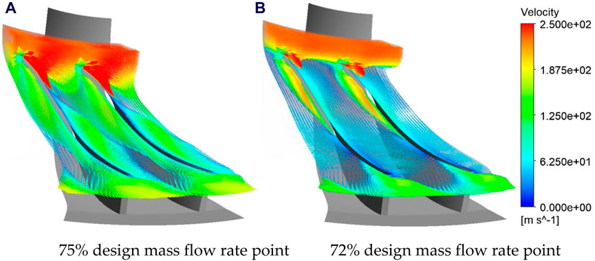
Figure 16. Velocity vector of 99% blade height for the initial design. (A) 75% design mass flow rate point. (B) 72% design mass flow rate point.
The velocity contour and vector of the 99% blade height at different flow conditions for the optimized design are shown in Figures 17, 18, respectively. At the point of highest pressure ratio, local flow separation occurs in the midstream region, forming a low-speed region that merges into the downstream wake region. When the flow rate is further reduced to 72% design mass flow point, the point of local flow separation moves upstream, while the downstream flow deteriorates, and the area of the wake region increases, mainly due to flow separation in the downstream region. However, the expanded wake region does not completely block the flow passage, and the scale of the wake vortex is also limited to the midstream and downstream regions. Therefore, although the flow within the flow field deteriorates, it still maintains certain flow and pressure boosting capabilities, and the compressor does not completely destabilize. When the flow rate is further reduced to 66% design mass flow point, the downstream wake region completely blocks the impeller passage, and the backflow mass has not yet developed to the leading edge of the blade. Considering the poor pressure boosting capability at this point, it is considered as the point of instability. However, at this point, the pressure ratio is still higher than the calculated result under the initial design condition of 72% design mass flow point.
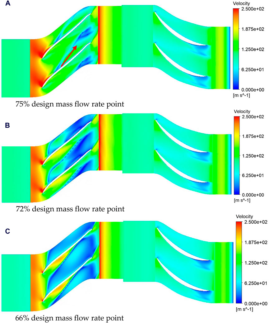
Figure 17. Velocity contour of 99% blade height after optimization. (A) 75% design mass flow rate point. (B) 72% design mass flow rate point. (C) 66% design mass flow rate point.
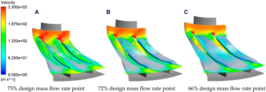
Figure 18. Velocity vector of 99% blade height after optimization. (A) 75% design mass flow rate point. (B) 72% design mass flow rate point. (C) 66% design mass flow rate point.
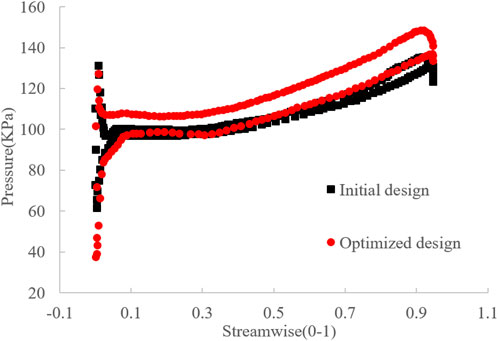
The above outlined the process of determining instability points for the initial and optimized solutions. The following text further elucidates the reasons behind the enhanced stability of the optimized solution by comparing the flow field information before and after optimization. Figure 19 illustrates the utmost streamlines on the pressure and suction surfaces of the blades for both the original and optimized solutions. In the original solution, flow separation occurs on the suction surface in the high blade height region near the leading edge of the blade, and as it progresses downstream, the separation point moves towards lower blade heights, resulting in an increasing separation area. However, in the optimized solution, although flow separation still occurs at high blade heights near the inlet, it reattaches in the midstream region of the blade and does not develop along the span. Separation occurs again only in the mid-to-lower stream, resulting in a much smaller separation area compared to the initial design. On the pressure surface, the flow state in the original solution is also poor in the high blade height region, with localized separation areas in the mid-to-lower stream. However, the flow state on the pressure surface of the optimized primitive level is good. Flow separation severely affects the aerodynamic performance of the blades, as indicated in Figure 20. The blade loading in this condition is much lower in the original solution, far less than in the optimized solution, which is also the reason for the sudden drop in pressure ratio in the original solution at this condition. At this point, although the pressure ratio in the optimized solution has decreased, it still maintains a certain aerodynamic performance.
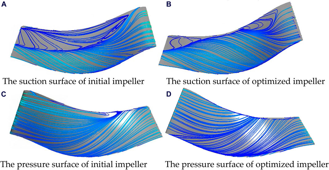
Figure 19. Utmost streamlines on initial and optimized scheme at 72% design mass flow rate point. (A) The suction surface of initial impeller. (B) The suction surface of optimized impeller. (C) The pressure surface of initial impeller. (D) The pressure surface of optimized impeller.
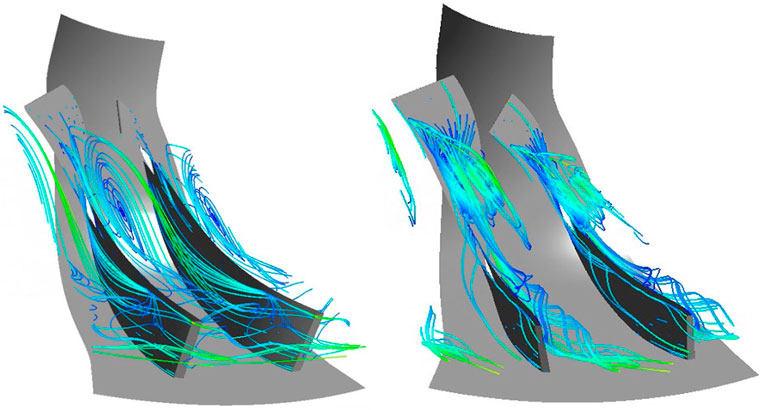
The flow state following flow separation on the blade surface is depicted in Figure 21. It is evident that in the original design, the separated flow generates a large-scale streamwise vortex that spans the entire impeller passage. This vortex entraps the separated flow and wake vortex, with its periphery nearing the blade’s leading edge, obstructing the entire impeller passage and inducing flow instability. Conversely, in the optimized design, a portion of the separated flow at the leading edge of the blade forms a vortex structure perpendicular to the blade surface, while another segment progresses downstream and merges into the wake region. The vortex structure perpendicular to the blade surface exerts a certain obstructive effect on the blade’s leading edge, while the downstream-developing separated flow expands the wake region. Nonetheless, neither flow segment forms a large-scale streamwise vortex, thus limiting its obstruction of the passage.
In conclusion, both the performance characteristics’ calculation results and the internal flow analysis indicate that the optimized solution has improved the stability on the low-flow conditions compared to the original design. Meanwhile, it ensures that the performance under other conditions does not show significant degradation, thereby achieving optimization.
5 Conclusion
This paper analyzes and optimizes a mature centrifugal compressor design for a large flow coefficient in engineering. Due to the compressor’s long blades and complex internal flow characteristics, the design of its main dimensionless aerodynamic structural parameters differs significantly from conventional parameters, rendering empirical optimization methods ineffective. Therefore, it requires special theoretical design methods to conduct thermodynamic aerodynamic analysis suitable for high flow coefficients, increasing the difficulty of optimizing centrifugal compressors.
To address these challenges, firstly, based on the theory of maximum flow capacity, a one-dimensional redesign of the centrifugal compressor design is conducted to determine the blade angle that minimizes the inlet Mach number, thereby maximizing the reduction of flow losses. This theory establishes a general relationship between geometric and aerodynamic parameters, mainly including the flow coefficient, dimensionless inlet diameter of the impeller, coefficient of power deviation, and dimensionless outlet width of the impeller. These parameters can link all the main dimensionless parameters of the centrifugal compressor, reflecting the coupling and constraint laws between geometry, flow field, and aerodynamic parameters, thereby obtaining the physical boundaries of the design space and optimization limits. Based on the new design, a parameterized modeling method is adopted for automatic multi-objective optimization. To avoid the occurrence of local optima in gradient-based optimization algorithms, a gradient mutation operation is introduced on the basis of the multi-objective algorithm NSGA-II, leading to the development of the gradient mutation hybrid optimization algorithm, significantly improving the efficiency and robustness of multi-objective optimization. By using CFD method verified this optimization enhances the performance of the original centrifugal compressor design at the design point and broadens its operating range under low-flow conditions, achieving optimization of the original design. Based on Stenning’s surge criterion, the flow field calculation results show that the flow separation area of the blade in the optimized scheme is far away from the primitive level, the pressurization capacity and flow stability on the low-flow conditions are better.
The current paper demonstrates an optimization concept that combines both physical principles and artificial intelligence tools. And this concept will provide a new idea for the optimization of the centrifugal compressor in the future. On the one hand, with the development of industry, the centrifugal compressor with better performance is more and more importan. On the other hand, with the development of centrifugal compressor design technology, it is more and more difficult to improve its efficiency. Under this background, the artificial intelligence tools should be made full use to assist the design of centrifugal compressor. However, designers should not rely entirely on AI tools because, in essence, AI tools can only find optimal solutions at the mathematical level. Therefore, it should be based on physical principles, given appropriate preconditions, and then the rational use of AI tools. In addition, in the use of artificial intelligence tools, but also should fully consider the advantages and disadvantages of various algorithms. As this paper proposed a combination of NSGA-II and gradient mutation algorithm, can ensure not to fall into the local optimal at the same time, to ensure the efficiency and robustness.
Data availability statement
The original contributions presented in the study are included in the article/supplementary material, further inquiries can be directed to the corresponding author.
Author contributions
CY: Conceptualization, Formal analysis, Investigation, Writing–original draft, Writing–review and editing. LF: Conceptualization, Project administration, Writing–review and editing, Funding acquisition. SC: Writing–original draft, Writing–review and editing, Validation, Investigation. HZ: Writing–original draft, Writing–review and editing, Resources, Supervision. YW: Writing–original draft, Writing–review and editing, Data Curation, Visualization.
Funding
The author(s) declare that financial support was received for the research, authorship, and/or publication of this article. This research was funded by the National Science and Technology Major Project of China (2017-V-0005-0055).
Conflict of interest
Authors CY and SC were employed by Dongfang Turbine Co., Ltd.
The remaining authors declare that the research was conducted in the absence of any commercial or financial relationships that could be construed as a potential conflict of interest.
Publisher’s note
All claims expressed in this article are solely those of the authors and do not necessarily represent those of their affiliated organizations, or those of the publisher, the editors and the reviewers. Any product that may be evaluated in this article, or claim that may be made by its manufacturer, is not guaranteed or endorsed by the publisher.
References
An, Z., Zhounian, L., Linlin, C., Peng, W., and Dazhuan, W. (2016). Multi-objective optimization of a low specific speed centrifugal pump using an evolutionary algorithm. Eng. Optim. 48, 1251–1274. doi:10.1080/0305215x.2015.1104987
Baljé, O. E. (1964). A study on reynolds number effects in turbomachines. J. Eng. Power 86 (3), 227–235. doi:10.1115/1.3677584
Bruce, G. J., Masme, M., and Mech, I. (1998). Computer-aided turbomachinery design system. New York, Basel: Marcel Dekker.
Chen, Z., Zuo, W., Zhou, K., Li, Q., Huang, Y., and E, J. (2023). Multi-objective optimization of proton exchange membrane fuel cells by RSM and NSGA-II. Energy Convers. Manag. 277, 116691. doi:10.1016/j.enconman.2023.116691
Dean, R. C., and Senoo, Y. (1960). Rotating wakes in vaneless diffusers. Trans. Asme J. Basic Eng. 82 (3), 563–570. doi:10.1115/1.3662659
Demeulenaere, A., Bonaccorsi, J. C., Gutzwiller, D., Hu, L., and Sun, H. (2015). “Multi-disciplinary multi-point optimization of a turbocharger compressor wheel,” in Asme Turbo Expo: Turbine Technical Conference and Exposition, Montreal, CA, June 15–19, 2015.
Denton, J. D. (1993). Loss mechanisms in turbomachines. Trans Asme J. Turbomach. 115 (4), 621–656. doi:10.1115/1.2929299
Eckardt, D. (1975). Closure to discussion of instantaneous measurements in the jet-wake discharge flow of a centrifugal compressor impeller. J. Eng. Power 97 (3), 346. doi:10.1115/1.3445999
Garvey, D. S., and Pim, A. (2016). Chapter 5-Compressed air energy storage. With special reference to renewable energy sources, 87–111.
Guelich, J. F. (2003). Effect or reynolds number and surface roughness on the efficiency of centrifugal pumps. J. Fluids Eng. 125 (4), 670–679. doi:10.1115/1.1593711
Ibaraki, S., Braembussche, R. V. D., and Verstraete, T. (2015). Aerodynamic design optimization of centrifugal compressor impeller based on Ibgenetic algorithm and artificial neural network. Mitsubishi Heavy Ind. Tech. Rev. 52 (1), 77. doi:10.1533/978081000342.65
Inoue, M., and Cumpsty, N. A. (1984). Experimental study of centrifugal impeller discharge flow in vaneless and vaned diffusers. J. Eng. Power 106 (2), 455–467. doi:10.1115/1.3239588
Kang, H. S., and Kim, Y. J. (2016). A study on the multi-objective optimization of impeller for high-power centrifugal compressor. Int. J. Fluid Mach. Syst. 9 (2), 143–149. doi:10.5293/ijfms.2016.9.2.143
Kang, K. J., Shin, Y. H., Kim, K. H., and Lee, Y. P. (2010). “Effect of diffuser contraction for a centrifugal compressor,” in Asme Joint Us-european Fluids Engineering Summer Meeting Collocated with International Conference on Nanochannels, Montreal, CA, August 1–5, 2010.
Kim, J. H., Choi, J. H., Husain, A., and Kim, K. Y. (2009). “Design optimization of a centrifugal compressor impeller by multi-objective genetic algorithm,” in Proceedings of the ASME 2009 Fluids Engineering Division Summer Meeting, Vail, USA, August 2–6, 2009.
Krain, H. (1984). A CAD method for centrifugal compressor impellers. J. Eng. Gas Turbines Power 106 (2), 482–488. doi:10.1115/1.3239591
Krain, H. (2005). Review of centrifugal compressor’s application and development. J. Turbomach. 127 (1), 25–34. doi:10.1115/1.1791280
Krain, H., and Hoffmann, B. (2007). Flow study of a redesigned high pressure ratio centrifugal compressor. J. Propuls. Power 24 (5), 1117–1123. doi:10.2514/1.35559
Li, J., Zuo, W., E, J., Zhang, Y., Li, Q., Sun, K., et al. (2022). Multi-objective optimization of mini U-channel cold plate with SiO2 nanofluid by RSM and NSGA-II. Energy 242, 123039. doi:10.1016/j.energy.2021.123039
Lin, Y., Zheng, X., Jin, L., Tamaki, H., and Kawakubo, T. (2012). A novel experimental method to evaluate the impact of volute’s asymmetry on the performance of a high pressure ratio turbocharger compressor. Sci. China Technol. Sci. 55 (6), 1695–1700.
Long, Q., and Wu, C. (2014). A hybrid method combining genetic algorithm and hooke-jeeves method for constrained global optimization. J. Industrial Manag. Optim. 10 (4), 1279–1296. doi:10.3934/jimo.2014.10.1279
Lüdtke, K. H. (2004). Process centrifugal compressors aerodynamic compressor design. Heidelberg, Germany: Springer.
Pinarbasi, A. (2008). Experimental hot-wire measurements in a centrifugal compressor with vaned diffuser. Int. J. Heat Fluid Flow 29 (5), 1512–1526. doi:10.1016/j.ijheatfluidflow.2008.04.011
Rohne, K. H., and Banzhaf, M. (1991). Investigation of the flow at the exit of an unshrouded centrifugal impeller and Comparison with the “classical” jet-wake theory. J. Turbomach. 113 (4), 654–659. doi:10.1115/1.2929131
Rubino, B. D. T., Grimaldi, A., Tapinassi, L., Sassanelli, G., Oil, G. E., et al. (2024). Renewing the stage-family portfolio to maintain a leading position in the evolving centrifugal compressor sector. Houston, Texas: General Electric Company
Sevastyanov, V. (2010). “Hybrid multi-gradient explorer algorithm for global multi-objective optimization,” in 13th AIAA/ISSMO Multidisciplinary Analysis Optimization Conference, Fort Worth, Texas, September 13–15, 2010.
Veress, A., and Braembussche, R. V. (2004). Inverse design and optimization of a return channel for a multistage centrifugal compressor. J. Fluids Eng. Trans. ASME 126 (5), 799–806. doi:10.1115/1.1792258
Wang, L., Han, R., Wang, T., and Ke, S. (2018). Uniform decomposition and positive-gradient differential evolution for multi-objective design of wind turbine blade. Energies 11 (5), 1262. doi:10.3390/en11051262
Yagi, M., Nishioka, T., Kobayashi, H., Nishida, H., and Yamamoto, S. (2015). “Effects of return channel with splitter vanes on performance of multistage centrifugal compressor,” in ASME Turbo Expo 2015 Turbine Technical Conference and Exposition, Montreal, CA, June 15–19, 2015.
Yang, C., Fan, L., Yan, W., and Zhang, H. (2024). The design and testing of a high reaction turbine blade profile. J. Phys. Conf. Ser. 2707, 012151. doi:10.1088/1742-6596/2707/1/012151
Yang, C., Fan, L., Zhong, Z., and Zhang, H. (2023). Numerical and experimental investigation on flow field of the turbine stage under different axial gaps. Processes 11 (7), 2138. doi:10.3390/pr11072138
Zuo, W., Li, D., Li, Q., Cheng, Q., Zhou, K., and E, J. (2023). Multi-objective optimization of multi-channel cold plate under intermittent pulsating flow by RSM and NSGA- for thermal management of electric vehicle lithium-ion battery pack. Energy 283, 129085. doi:10.1016/j.energy.2023.129085
Keywords: centrifugal compressor, maximum flow capacity theory, automatic optimization, large-flow coefficient, variable operating conditions characteristics
Citation: Yang C, Fan L, Chen S, Zhang H and Wu Y (2024) Research on optimization methods for large-flow coefficient centrifugal compressors. Front. Energy Res. 12:1432725. doi: 10.3389/fenrg.2024.1432725
Received: 14 May 2024; Accepted: 24 July 2024;
Published: 20 August 2024.
Edited by:
Lin Ma, The University of Manchester, United KingdomReviewed by:
Aqiang Lin, Northwestern Polytechnical University, ChinaWei Zuo, Wuhan University of Science and Technology, China
Copyright © 2024 Yang, Fan, Chen, Zhang and Wu. This is an open-access article distributed under the terms of the Creative Commons Attribution License (CC BY). The use, distribution or reproduction in other forums is permitted, provided the original author(s) and the copyright owner(s) are credited and that the original publication in this journal is cited, in accordance with accepted academic practice. No use, distribution or reproduction is permitted which does not comply with these terms.
*Correspondence: Liyun Fan, ZmFubGl5dW5AaHJiZXUuZWR1LmNu
 Changzhu Yang1,2
 Yuelin Wu