 Abdelhakim Merdjani
 Natalia Kizilova1
 Tabbi Wilberforce Awotwe
- 1Warsaw University of Technology, Institute of Aeronautics and Applied Mechanics, Warszawa, Poland
- 2Faculty of Natural, Mathematical and Engineering Sciences, Kings College London, London, United Kingdom
- 3Faculty of Transport, Warsaw University of Technology, Warsaw, Poland
Proton Exchange Membrane Fuel Cells (PEMFCs) have received increasing attention as a renewable energy technology with the potential to reduce greenhouse gas emissions and reduce reliance on fossil fuels. This review presents the advancements and challenges associated with flow field plates (FFPs) and cooling systems in PEMFC with a particular emphasis on the exploration and integration of bio-inspired designs which inspiration from natural structures offers unique solutions for uniformity of fuel and heat distribution. A comparative study on the innovative nature-inspired designs and conventional designs for FFPs and cooling systems is presented. Various fabrication methods of FFPs assessing their feasibility and economic implications are discussed. The comparative analysis aims to offer a holistic view on the current landscape and future directions in PEMFC technology, highlighting the importance of efficient design and manufacturing strategies to meet the growing demands for sustainable and efficient energy solutions.
1 Introduction
Fuel cell (FC) technology is a clean and efficient way to convert the chemical energy of fuels such as hydrogen, natural gas, methanol, and ethanol into electric energy with significantly high efficiency and much lower greenhouse-gas emission as compared to well-established internal combustion engine technologies. FCs can be categorized according to the nature of the electrolytes, including low-temperature Proton Exchange Membrane fuel cells PEMFCs, alkaline fuel cells (AFCs), phosphoric acid fuel cells (PAFCs) to high-temperature molten-carbonate fuel cells (MCFCs) and solid-oxide fuel cells (SOFCs) (see Figure 1) (Steele and Heinzel, 2001), (Mekhilef et al., 2012), (Ebrahimi et al., 2021), (Pan et al., 2024).

Figure 1. Overview of various types of FCs (from (Ebrahimi et al., 2021), open access).
As shown in Figure 2, FCs are used in a variety of applications including primary and backup power for commercial, industrial, and residential buildings, as well as in remote or inaccessible areas. They are also used to power FC vehicles, including automobiles, buses, trains, boats, motorcycles, airplanes, submarines and drones (Sebbani et al., 2025), (Olabi et al., 2021).
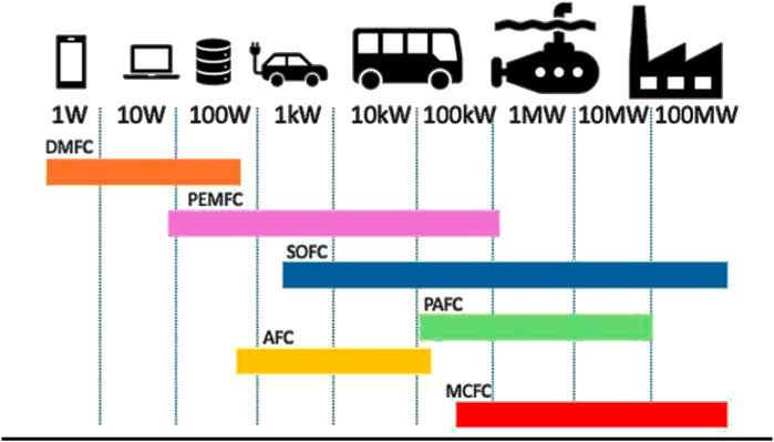
Figure 2. Application sectors of FC technology with different power (based on (Sebbani et al., 2025)).
As PEMFCs continue to gain attention as a clean energy solution, their significance is heightened by their utilisation of hydrogen as a fuel; this type of FC efficiently converts hydrogen into electricity. The components of PEMFC include (Figure 3a) the PEM, catalyst layer (CL), gas diffusion layer (GDL), FFPs for fuel delivery and charge collection, and the cooling system. The PEM with two CLs sandwiched between two GDLs form the membrane-electrode assembly (MEA). The electrochemical reactions occurring in PEMFC (Figure 3b) are as follows:
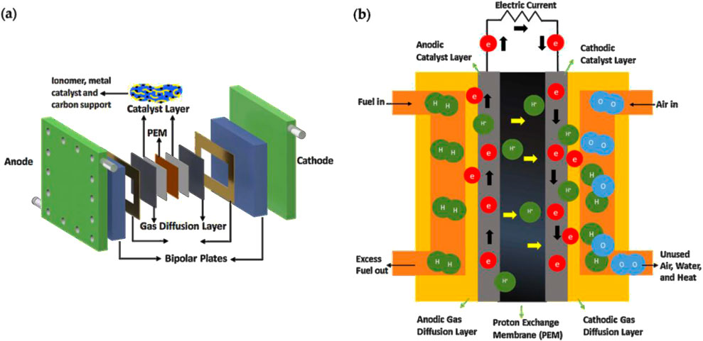
Figure 3. PEMFC components (a) and description of its operation (b) (from (Madhav et al., 2024), open access).
In this process, electrons flow from the anode to the cathode through an external circuit, generating electrical power, while protons move through the PEM to the cathode to complete the reaction, forming water as the only by-product. The heat produced in the chemical reactions Equations 1–3 is removed by a cooling system located outside the FC that prevents the MEA from overheating and further degradation.
The design and optimization of FFPs have become subjects of intense research and development. FFPs not only impact the overall performance of PEMFCs but also influence such factors such durability, cost-effectiveness, manufacturability, and lifespan. Consequently, a comprehensive understanding of FFP design principles, materials selection, manufacturing techniques, and their implications on PEMFC performance is essential to unlocking the full potential of this technology (Zhang et al., 2024; Wang and Jiang, 2017; Shekhawat et al., 2011; Chen et al., 2019).
The FFP is a very important multi-functional component of the FC; it supplies fuel (H2) and oxidant (O2 or air) to the MEA, removes water outside the FC, collects electrons produced in the system and carries the current from the MEA to the end plates of the PEMFC stack. The bipolar plates also serves as separators between two adjacent FCs and their connector in the PEMFC stack. Bipolar plates provide fast efficient removing the heat generated in the chemical reactions Equations 1–3 by conducting it away from the MEA. The FFPs comprise ∼50–60% of the weight, ∼50% of the volume, and ∼30–40% of the total cost of the FC stack (Figure 4) (Tang et al., 2021; Song et al., 2021). It plays a vital role in distributing reactants evenly across the cell to provide efficient electrochemical reactions and longevity time. Therefore, design optimization and improvement of operating conditions contributes significantly to reduction in both weight and price of FC stack.
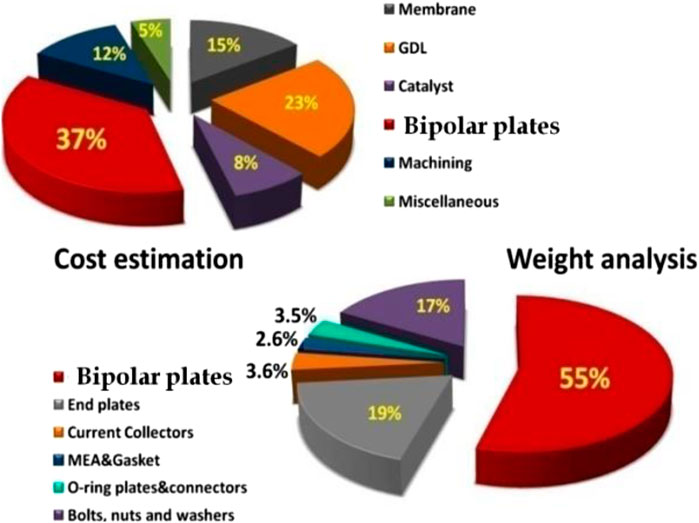
Figure 4. Weight and cost percentage of FFPs in PEMFC (from (Yeetsorn, 2010)).
Proper design and fabrication of FFPs in PEMFCs are important for optimal reactant transport, uniform gas distribution, low-pressure drop for fuel pumping, and timely water removal from the FC. All these factors highly determine the performance (i.e., resulting electric current at a given flow rate of the fuel) and efficiency (a ratio of the useful and applied energies) of the PEMFCs. Over the recent years, there has been an increased interest in optimizing the design and fabrication of FFPs for their better performance in PEMFCs. Researchers have considered various FFP designs for bipolar plates, such as serpentine, parallel, interdigitated, and mesh types or their combinations. Besides, 2D circular and 3D tubular geometry, porous, fractal, and biomimetic FFP designs, which facilitate gas distribution, control water management, and improve the overall performance of the PEMFC have been elaborated and tested. However, each design also comes with its cons and trade-offs, therefore making it difficult to select a single optimal FFP. Because of such challenges involved in the design and fabrication of FFPs, researchers have conducted a lot of studies in theoretical models, numerical simulations and experimental studies on different types of FFPs. They have figured out that proper design and fabrication of FFPs can greatly enhance the performance and efficiency, and decrease the overall cost of PEMFCs (Shaigan et al., 2021; Hermann et al., 2005; Dihrab et al., 2009; Mehta and Cooper, 2003).
During the last decades, the FFP design and its influence on the efficiency and durability of FCs has been a subject of a series of review papers that confirmed existence of different combinations of the FFP geometry, material and operating conditions for better performance (Marappan et al., 2021; Yan et al., 2023; Zhang and Tu, 2024; Xiong et al., 2021). Marappan et al. (2021) analysed how different conventional flow field (FF) configurations, such as serpentine, parallel, interdigitated, and pin-type, affect the efficiency, water management, pressure drop, and overall performance of PEMFCs. The review synthesizes findings from numerous experimental and computational studies to present a comprehensive understanding of the impact of the FFdesign on PEMFC operation. The paper also discusses the advantages and limitations of conventional designs. Yan et al. (2023) provided a detailed analysis of various conventional FFP designs and their influence on FC performance metrics such as power output, efficiency and durability. The authors synthesized recent advances in materials and fabrication technologies for FFP and discussed their implications for improving PEMFC efficiency. Zhang and Tu (2024) explored different designs of FFP in PEMFC and addressed challenges like gas distribution, water flooding and high pressure drops, summarized recent advancements in FFP designs and manufacturing techniques aimed at improving gas diffusion, water management and efficiency. The review also discussed the role of computational modelling and experimental validation in design optimization. Xiong et al. (2021) discussed various modelling techniques used for design optimization of FFP, including computational fluid dynamics (CFD). They review different materials used for bipolar plates, such as graphite, metals, and composites, evaluating their performance, cost, and durability. The paper also explored various fabrication methods, including machining, moulding, and additive manufacturing (AM), highlighting advancements and challenges of each one.
This review paper aims to provide an in-depth examination of FFP designs in PEMFCs with a special emphasis on the bio-inspired designs. The bio-inspired designs follow geometry of natural structures like plant leaves, human lungs and arterial systems, which are estimated as an outcome of evolutionary optimization. Therefore, the FCs with bio-inspited designs of FFPs exhibited higher output power, better water management capacity, and more uniform reactant distribution over the PEM. It was confirmed by numerous theoretical, experimental and CFD studies, which are reviewed and analysed here. Through a meticulous analysis of existing literature and a synthesis of key findings, we will delve into the historical evolution of FFPs and cooling systems, elucidate the critical parameters that govern their design, explore the materials employed in their fabrication, and discuss the various manufacturing techniques used. Additionally, we will evaluate the methods to assess FFP performance, including mass transport, pressure drop, and power output.
In our review, we will focus on promising bio-inspired designs and compare them to conventional FFP designs. We will also connect FFP designs and manufacturing techniques with the actual cost of FFPs in the market, highlighting the economic aspects. Moreover, we will emphasize the important role of coolant channels in improving PEMFC performance and reducing overall weight.
By navigating this comprehensive overview of FFP design, readers will gain valuable insights into the fundamental principles and the latest developments in the critical aspects of PEMFCs. Ultimately, this review aims to contribute to the ongoing progress in the field, inspiring researchers and engineers to push the boundaries of FFP design and drive the widespread adoption of PEMFCs as a clean and sustainable energy source.
2 Role of FFP in PEMFC
The FFP of PEMFCs must be designed for the attainment of several factors, responsible for the overall performance and efficiency. The FFP ensures not only easy transportation of reactants, but also uniform distribution of the fuels, low pressure drop for their pumping through the FFP and MEA, and effective water management in the system. Apart from the functions above, the FFP must also offer optimum electrical and thermal conductivity (Ruan et al., 2016; Hamilton and Pollet, 2010).
• Distribution of reactant gases:
The core operation of a PEMFC involves the supply of hydrogen and oxygen to the anode and cathode, respectively. FFPs are meticulously engineered to ensure a homogeneous distribution of these gases across the MEA active surface. Achieving an even distribution is pivotal for uniform chemical reactions throughout the MEA (Lim et al., 2016), (Obayopo et al., 2012), (Tiss et al., 2014).
• Heat management:
Effective thermal management is essential for the performance and longevity of PEMFCs. The electrochemical reactions Equations 1–3 within the cell generate heat, which, if not properly dissipated, can increase the temperature of the PEMFC and negatively affect its components. FFPs, constructed from conductive materials, are critical for the uniform distribution of heat throughout the cell (Wang et al., 2011; Nöst et al., 2018).
• Water management:
Water management within a PEMFC is also crucial for its efficiency. The generation of water as a by-product of electrochemical reactions necessitates a delicate balance in water handling. Excessive water accumulation can lead to FC flooding, obstructing gas flow to the MEA and reducing the performance. The design of FFPs addresses this challenge by enabling precise water removal and maintaining proper hydration, thereby optimizing cell performance (Zhang et al., 2015; Cao et al., 2013; Kandlikar, 2008).
2.1 FFP designs
We can categorize the design of FFP into two primary groups: conventional designs along with their modifications, and bio-inspired designs that are derived from natural models, as illustrated in Figure 5.
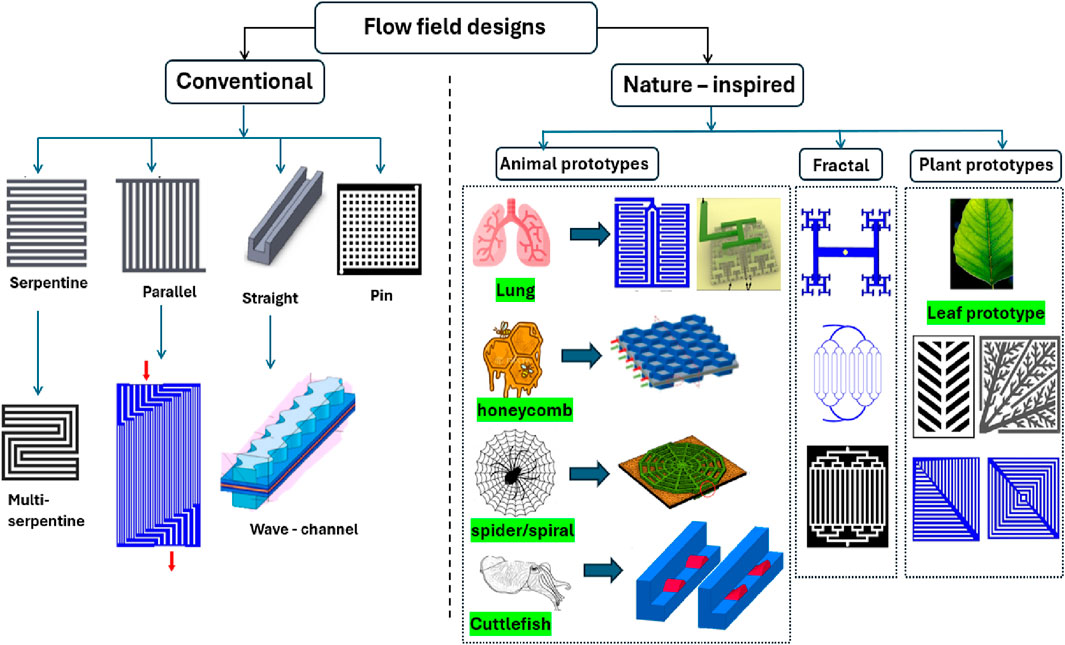
Figure 5. Classification of FFP designs in PEMFC (Merdjani et al., 2024).
2.1.1 Conventional designs and their modifications
The existing designs of FFP in PEMFC can be broadly categorized into conventional designs, their combinations (synthetic or hybrid design) and novel/modified designs. Conventional designs typically include parallel, serpentine, interdigitated and pin-type (or mesh-type) FFPs. The serpentine design involves channels that snake and forth across the flow field, that increases the path length for reactant gases and, therefore, the hydraulic resistivity of the FFP. The design may be based on a single serpentine channel (Figure 6a) or several parallel channels (Figure 6b). The parallel FFP includes straight channels that run from one end of the plate to the other (Figure 6c). The pin-type/mesh-type design replaces traditional channels with an array of pins or grooves that protrude from the plate by creating a more open FF(Figure 6d). The interdigitated design is composed by the interlaced parallel channels with open ends (Figure 6e) (Sierra et al., 2014; Sauermoser et al., 2020). The single-channel serpentine design is accepted as a ‘golden standard’, and novel FFP designs are usually compared to the efficiency of the serpentine cathode FFP at the same operating conditions. Different designs can be taken at the anode side for more uniform fuel distribution and heat generation, while the serpentine design is mostly used at the cathode side for better water removal. Any combinations of different conventional and non-conventional designs at two electrodes could be used. The most advancing designs and operating conditions, and their specifications are summarized in Table 1.
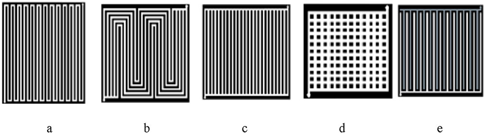
Figure 6. Schematic images of conventional FFP designs: single-channel serpentine (a), five-channel serpentine (b), parallel (c), pin-type (d), and interdigitated (e) (from (Sauermoser et al., 2020), open access).
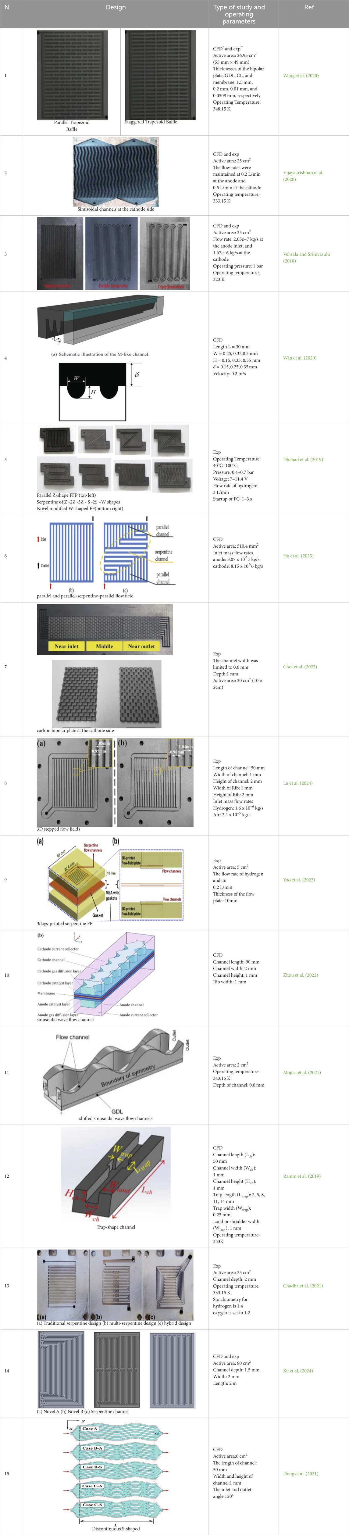
Table 1. Modifications of conventional design of FFP with their dimensions and operating parameters (*CFD means numerical simulations, **exp means experimental study).
As it follows from the variety of designs presented in Table 1, the attempts to improve performance of the FFP in fuel delivery (lower pressure drop), more uniform distribution of the gases, water management (easy and fast water removal from the FC), and higher electric voltage at given flow rate of the fuels and based on (i) modifications of the channel’s shape (rows N1, 4, 5, 12); (ii) variations (N3, 8, 9) or (iii) combinations (N6, 7, 13, 14) of conventional designs; and (iv) waved channels (N2, 10, 11, 15). The obtained rise in efficiency of the FC, advantages and disadvantages of each FFP design are summarized below.
Wang et al. (2020) (N1 in Table 1) combined numerical simulations and experimental tests to evaluate the effect of baffle plate arrangements in PEMFCs. The baffle plates, which optimize reactant distribution and enhance mass transfer, significantly improve FC performance; the study found that incorporating baffle plates increased the peak power density by 15.3%. Advantages include better water management and enhanced reactant distribution, while disadvantages involve potential increased pressure drop for fuel pumping and the need for precise manufacturing.
Vijayakrishnan et al. (2020) (N2 in Table 1) explored the impact of a sinusoidal channels at the cathode side on the PEMFC performance. Both numerical simulations and experimental tests were conducted on 5 × 5 = 25 cm2 and 10 × 10 = 100 cm2 FC. Results showed that the novel sinusoidal FFimproved water removal and enhanced performance, increasing the power density by 7.7% compared to conventional serpentine FFP. Combining sinusoidal and serpentine flow fields further increased the power density by 14%. Advantages include better water management and higher power density, while disadvantages involve potential complexity in manufacturing.
Velisala and Srinivasulu (2018) (N3 in Table 1) explored the performance of PEMFC with different flow channel configurations. Both numerical simulations and experimental tests were conducted on single (1-S), double (2-S), and triple (3-S) serpentine flow FFPs. The results showed that the 3-S configuration achieved the highest performance, with a 12.5% increase in power density compared to the single serpentine configuration due to improved reactant distribution and water removal. The study highlights advantages such as enhanced mass transport and reduced concentration losses, while disadvantages include the increased complexity and higher pressure drop for fuel pumping.
Wan et al. (2020) (N4 in Table 1) involved numerical simulations to optimize the M-like flow channel design. The M-like channel showed better performance (21.3% higher) in terms of heat and mass transfer compared to conventional designs. The optimized design resulted in reduced entropy generation and enhancing overall efficiency of the FC. Advantages include improved thermal and fluid management, while disadvantages could involve the complexity of manufacturing such channels.
Dhahad et al. (2019) (N5 in Table 1) examined the impact of different FF designs on PEMFC performance experimentally. The research compared eight parallel z-shape and w-shape channels, and found that novel design significantly enhance PEMFC efficiency by more uniform reactant distribution and more efficient water management. The best-performing design increased power density by 18%, highlighting its potential for improved performance. Advantages include better gas distribution and reduced water clogging, while disadvantages involve higher pressure drop needed for fuel pumping due to higher hydraulic resistivity of the z-shape and w-shape channels.
Hu et al. (2023) (N6 in Table 1) employed multi-physics coupling simulations to optimize the FF structure in PEMFC. The study revealed that the optimized structure significantly improves the uniformity of reactant distribution and water management, enhancing overall performance. The novel design reduced entropy generation and increased power density by 10%. Advantages include better thermal and water management, while disadvantages involve the complexity of implementing the optimized designs in practical applications.
Choi et al. (2022) (N7 in Table 1) investigated the effects of non-uniformly arranged 3D-printed metallic structures in the cathode flow channel of PEMFC. The study utilizes a 3D metal printer to create complex geometries, revealing that the non-uniform arrangement significantly enhances the mass transfer and performance. Advantages: the optimized design resulted in a 13% increase in maximum power density compared to uniform structures, with better gas distribution and reduced flooding. The main disadvantage is the complexity of manufacturing the intricate design.
Lu et al. (2024) (N8 in Table 1) explored the performance of 3D-printed FFP with novel stepped design of the channels width. The study, which includes both numerical simulations and experimental validation, found that the design significantly improves the mass and heat transfer, resulting in a 15% increase in power density compared to conventional designs. Advantages include improved efficiency and better water management, while disadvantages involve the complexity and cost of 3D printing of the complex multi-layer cell.
Yoo et al. (2022) (N9 in Table 1) explored the development and performance of bendable PEMFC using 3D-printed flexible FFP. The study includes experimental evaluations of the FC in both flat and bent positions. It was found, the PEMFC achieved a peak power density of 87.1 mW cm-2 when bent, compared to 30.2 mW cm-2 in the flat position. This enhancement is attributed to the compressive stress on the MEA during bending, which reduces ohmic and charge transfer resistances (advantages). The research highlights the potential of 3D printing in creating cost-effective, high-performance flexible FC with simple structures.
Zhou et al. (2022) (N10 in Table 1) examined the impact of an opposite sinusoidal wave flow channel on the performance of PEMFC. Through numerical simulations, the study explores how variations in the amplitude and period of the sinusoidal wave affect FC performance. The findings indicate that this novel flow channel design significantly enhances mass transfer and water removal capabilities, resulting in improved overall performance. The optimized flow channel design achieved an increase in power density in 16.6%, attributed to better gas distribution and reduced flooding. The main advantages include enhanced efficiency and effective water management, while potential disadvantages involve the complexity of fabricating such intricate designs.
Mojica et al. (2021) (N11 in Table 1) investigated the performance of PEMFC with converging-diverging flow channels. This design aims to enhance convective mass transport and improve overall cell efficiency. The study combines numerical simulations and experimental tests, finding that the converging-diverging channels lead to a 12% increase in power density compared to conventional flow channels. The improved performance is attributed to more effective reactant distribution and reduced concentration polarization. The main advantages include better mass transport and increased efficiency, while disadvantages involve potential complexities in channel manufacturing.
Ramin et al. (2019) (N12 in Table 1) investigated the impact of trap-shaped flow channels on the performance of PEMFCs. Through both numerical simulations and experimental validation, the study demonstrates that the innovative trap-shaped channels significantly improve power density by enhancing reactant distribution and water management. The results showed an increase in power density by 18% compared to conventional flow channels. The advantages of this design include more uniform gas distribution and reduced flooding, while disadvantages may involve increased complexity in the manufacturing process and potential high pressure drop for fuel pumping.
Chadha et al. (2021) (N13 in Table 1) explored the effects of hybrid multi-serpentine FF geometries on the performance of PEMFCs. Through numerical simulations and experimental analysis, the study focuses on improving water redistribution and reducing pressure head losses. The new geometries significantly enhance water management and reduce pressure losses, resulting in a 20% increase in power density compared to traditional designs. The advantages include improved efficiency and better water management, while disadvantages may involve the complexity of implementing these complex geometries in manufacturing processes.
Xu et al. (2024) (N14 in Table 1) investigated the performance of a novel coolant channel design for PEMFCs. The study employs both numerical simulations and experimental tests to analyse the impact of the designs on thermal management and overall cell performance. The findings revealed that the novel designs significantly enhances heat removal, leading to improved temperature uniformity and a 15% increase in power density compared to conventional serpentine design. Advantages include better thermal management and increased efficiency, while disadvantages might involve the complexity and cost of implementing the new coolant channel design.
Dong et al. (2021) (N15 in Table 1) investigated the effect of incorporating discontinuous S-shaped and crescent ribs into the flow channels of PEMFC. The study combines numerical simulations with experimental validation to assess how these novel rib configurations enhance FC performance. The results show that these designs significantly improve energy performance by optimizing reactant distribution and water management, leading to a 17% increase in power density compared to conventional flow channels. The main advantages include enhanced mass transport and reduced water flooding, while the disadvantages involve the complexity and potential cost of manufacturing of the intricate rib structures and potential increases in pressure drop for pumping.
Therefore, modifications of the shape of the channels (trapezoidal, waved, stepped, m-shape, w-shape, S-shape, etc.) and their arrangement on the FFP (z-type, multi-serpentine, hybrid serpentine in combination with parallel, etc.) allow improvement of the FC efficiency in 7.7%–21.3%. The increase in efficiency of the FFP designs N1-15 cannot be accurately compared due to different size and operating parameters of the prototypes and different CFD models used in numerical simulations. In general, modifications of the cross-sectional shape of the channels (trapezoidal N1, stepped variation in the channel width N8, trap-shape width changes N12) increased the efficiency in 15.3, 15% and 18%, accordingly. Since the channels with varied width provide better flow mixing, it could be the main mechanism for improvement of the fuel distribution and heat transfer to the electrodes and, finally, to the cooling system. Waved channels in both in-plane (N2, N10, N15) and orthogonal (N11) planes also produce higher flow mixing that leads to the increase in the efficiency in 2.2, 16.6, 12, and 17%, accordingly. Flows in the waved channels does not experience sudden turn (180°) like in the serpentine flow, and the hydraulic resistance of the channels is reasonably low compared to the single-serpentine design. Therefore, such FFPs need lower pressure drop for pumping of the fuels at any given flow rate. Replacement of regular sudden turn 180° of the channel in the n-serpentine design by smooth circular arches (N3) increased the efficiency in 1.5%. A combination of parallel with single-serpentine (N6) increased the efficiency in 10%. Therefore, replacement of rectangle turns in (Hu et al., 2023) by the arches could be proposed for further improvement of N6 based on the results (Velisala and Srinivasulu, 2018). The highest rise in the efficiency (∼20%) was obtained for the channels with M-type cross section (N4, 21.3%), hybrid multi-serpentine design (N13, 20%), trap-shape channel (N12, 18%) and zig-zag channel (N5, 18%).
It is difficult to say, whether a combination of the elements (waved walls and cross-sectional geometry of channels, their location on the FFP, smoothed turns, combination with convenient designs) will produce a more efficient design, because the FC has a very complex composition, structure, chemical, physical and mechanical processes inside it. Anyway, the comparative analysis confirmed a significant importance of better flow mixing, low hydraulic resistance of the channels and low electric resistance of the components of PEMFCs for improvement of their efficiency in >20%. The disadvantages of almost all novel designs are connected with complex systems of channels which are difficult and costly for manufacturing.
2.1.2 Bio-inspired designs
Biologically inspired design (BID) methodology offers a systematic approach for designing based on natural tree-line flow fields that based on the length and width/diameter scaling in the consequent bifurcations of channels/tubes (Murray’s law) as explained in Equation 4 (Fan et al., 2022; Kizilova, 2004)
where
BID involves precise design steps, such as recognizing and applying biological techniques. Case studies have demonstrated the application of BID in creating innovative designs, such as fish-inspired and bird-inspired robots, and mastication robots. The principal gaining traction is Murray’s law (Pentelovitch and Nagel, 2022; Luo et al., 2020; Wang and Deng, 2022; Molina et al., 2020).
Recently, the concept of mimicking nature to enhance the design of FFP in PEMFC has garnered considerable attention. These innovative designs are inspired by the efficient transport mechanisms observed in natural systems, aiming to replicate their high efficacy in FCs. For instance, the branched and stepped FF designs draw their inspiration from the intricate network of veins in leaves or the vascular systems in animals as shown in Figure 7 (Fan et al., 2022; Kizilova, 2004). Some prototypes of biological design for FFP in PEMFC with their dimensions and operating conditions are presented in Table 2.
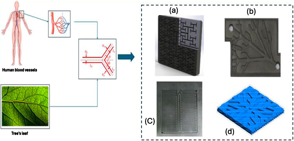
Figure 7. Bio-inspired designs of FFP in PEMFC. (a) Sauermoser et al. (2021), (b) Ghadhban et al. (2021), (c) Badduri et al. (2019), (d) Li et al. (2022a).
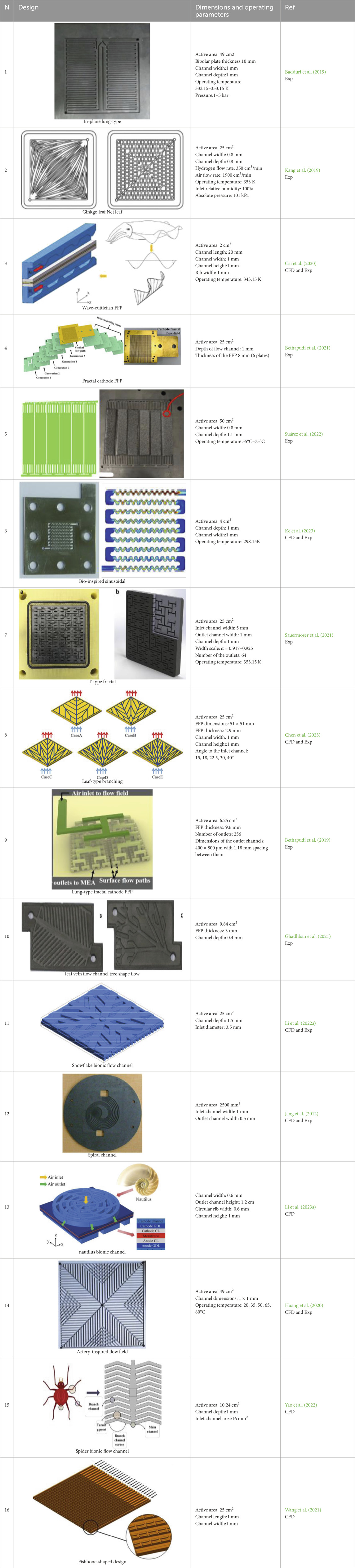
Table 2. Examples of bio-inspired designs of FFP in PEMFC.
A range of studies has compared the performance and efficiency of bio-inspired and conventional FFP designs in PEMFCs. Badduri et al. (Badduri et al., 2019) (N1 in Table 2) investigated the performance of novel lung channel design FFP experimentally. The lung channel design aims to enhance reactant distribution and water management within the FC. Results showed a significant improvement in performance, with a 19% increase in power density compared to traditional serpentine FFP (advantages). Kang et al. (Kang et al., 2019) (N2 in Table 2) experimentally investigated the system of channels inspired by ginkgo leaf and the rectangular network of channels of the same size. The maximum power density for the ginkgo-like FFP was 6.7% lower than that for the serpentine flow field, and 40% higher than that for the parallel FF under standard operating conditions. Cai et al. (Cai et al., 2020) (N3 in Table 2) analysed wave-like channel design inspired by cuttlefish and optimized using a genetic algorithm. The study combined numerical simulations with experimental validations to assess the performance improvements of this novel design. Results indicated that the bionic wave-like channel significantly enhances cell performance by improving reactant distribution and water management, leading to a 22% increase in power density compared to serpentine channel designs. Advantages include better mass transport and reduced flooding.
Bethapudi et al. (2021) (N4 in Table 2) explored the performance of PEMFC using a fractal FFP with T-junction (180° angle in the bifurcations) for cathode side. The consequent generations of the fractal channels of different generations (j = 1,2,3,4,5) were carved in different plates that increased the thickness of the FFP. The study combined numerical simulations and experimental methods to evaluate the electro-thermal characteristics of this novel design. Results indicated that the fractal FFP significantly improved thermal management and increased the uniformity of current density distribution (advantages), leading to a 20% increase in power density compared to serpentine flow field. However, the complexity and potential cost of manufacturing such intricate designs are noted as (disadvantages). Suárez et al. (Suárez et al., 2022) (N5 in Table 2) explored the impact of fractal inlet and outlet (2 generations) to the active area of the PEMFC on its performance. The study employed both numerical simulations and experimental testing to evaluate several bio-inspired flow channel structures, including designs based on leaves, lungs, and sponges. The most promising design was selected, manufactured, and tested. Results showed that the proposed FFP, particularly the design incorporating hydrophobic graphene porous sponge inserts, significantly improved water management and performance even at high relative humidity, achieving a 6% increase in peak power density compared to the conventional parallel-serpentine designs.
Ke et al. (2023) (N6 in Table 2) investigated the effects of bio-inspired sinusoidal channels on the performance of PEMFC. Through both numerical simulations and experimental tests, the study evaluated how this design can increase the power density produced by PEMFC. The results showed that the sinusoidal flow channels significantly enhance oxygen transport and reactant distribution, leading to a 15% increase in power density compared to serpentine flow channel. The advantages include improved mass transport and reduced oxygen starvation, while disadvantages involve the complexity and potential cost of manufacturing. Sauermoser et al. (Sauermoser et al., 2021) (N7 in Table 2) investigated the impact of varying channel widths in tree-like T-type fractal FF on PEMFC performance. Since the outlets of the T-type fractal with six to seven generations uniformly distributed over the square or rectangle area of MEA, the reactants are delivered to the PEM more uniformly. The experimental study with relative humidity of hydrogen RH = 50%, 60%, 70% revealed, a decrease in the width-scaling parameters α led to improved PEMFC performance. The best performance were detected at RH = 70%, and the corresponding performance was 11% lower compared to the serpentine FFP at the same flow rates and RH. Among the disadvantages is water accumulation in the channels, which is the main reason for reducing power density.
Chen et al. (2023) (N8 in Table 2) investigated the use of a tree-like fractal channels inspired by palmate venation of some leaves for cooling FF in PEMFC to improve temperature distribution and cooling capacity. Using both numerical simulations and experimental analysis, the study found that the fractal cooling FF achieved better coolant distribution and temperature uniformity compared to parallel and serpentine flow fields. The results show a reduction in maximum temperature from 340.7 K to 337.8 K and improved temperature uniformity, making the fractal design effective in solving local overheating issues (advantages).
Bethapudi et al. (2019) (N9 in Table 2) explored the use of a lung-inspired fractal flow-field design in PEMFC. This design aims to provide homogeneous and uniform distribution of reactants by mimicking the airflow mechanism in human lungs. The study involved both experimental and numerical analyses, and the fractal flow-fields are fabricated using low-cost, lightweight printed circuit boards (PCBs). The performance of these lung-inspired flow-fields was found higher than the single-serpentine flow-fields, especially under conditions of low RH (advantages). The 3D fractal tree is difficult for manufacture but it can be produced by 3D-printing technology. Ghadhban et al. (Ghadhban et al., 2021) (N10 in Table 2) examines the impact of FF designs inspired by pinnate venation of some leaves and by tree branches. The study finds that these designs, which mimic natural patterns, significantly enhance water management and reactant distribution, leading to a 15% increase in power density compared to conventional serpentine flow fields. The proposed bio-inspired designs improve water management, reducing flooding and maintaining more stable performance at higher current densities. They also achieve better uniformity in reactant distribution and reduce pressure drops by 10% (advantages).
Li Y. et al. (2022) (N11 in Table 2) examines the use of a snowflake-shaped bionic FF to enhance PEMFC performance. By integrating the advantages of leaf vein and lung-shaped channels, this design aims to improve gas supply uniformity and reduce pressure drop. Utilizing a 3D multi-physics FC model, the study shows that the snowflake bionic design significantly reduces pumping work and enhances flow uniformity (advantages). For the peak power density, the snowflake FF design had a 27%, 66% and 45.5% higher values compared to the leaf vein, lung-type and double-serpentine FFS, accordingly. After optimization, the non-uniformity of the fuel flow rates between the outlets of the FF was reduced by 29.98% compared to the non-optimized design.
Jang et al. (2012) (N12 in Table 2) explored the performance of PEMFC with spiral flow channels. Through a combination of numerical simulations and experimental tests, the study investigated how these spiral channels affected the FC’s efficiency and performance. The results show that the spiral flow channels significantly enhance reactant distribution and water management within the FC. Specifically, the spiral channels increased the average current density by 11.9% compared to conventional serpentine channels. Additionally, the spiral design contributed to a reduction in pressure drop (advantages). Li N. et al. (2023) (N13 in Table 2) investigated the use of a nautilus-inspired FF design to enhance PEMFC performance. Through numerical simulations and experimental analyses, the study showed that the nautilus bionic FF significantly improves reactant distribution and reduces pressure drops compared to conventional serpentine FF. The best increase in power density in comparison to the serpentine FF at ∼8% was achieved. Huang et al. (2020) (N14 in Table 2) explored the implementation of a bionic FF inspired by the structure of the superior mesenteric artery in human. Through numerical simulations and experimental tests, the study demonstrated that this design improves the FC performance by enhancing water removal and reactant distribution over the PEM. The mesenteric artery-based FF increased the droplet removal rate by 36.3% and improved the power density by 12.5% compared to conventional serpentine flow fields. This design effectively addresses issues of pressure drop (advantages).
Yao et al. (2022) (N15 in Table 2) explored the performance improvements of PEMFC using a spider web-inspired FF design. Through both numerical simulations and experimental studies, the research demonstrated that the spider bionic FF significantly enhanced reactant distribution and water management. Compared to serpentine flow channels, the spider bionic design improved power density by 9% and reduced pressure drop by 13%. These enhancements are attributed to more uniform distribution of reactants, as well as better removal of water from the channels (advantages). Wang et al. (2021) (N16 in Table 2) examined the effectiveness of a nature-inspired fishbone-shaped cathode FF in PEMFC. Using numerical simulations and experimental analyses, the study found that this bio-inspired design significantly improved mass transport and water removal compared to parallel flow field. Specifically, the fishbone design enhanced power density by 18% and reduced pressure drop by 22% (advantages).
Therefore, bionic nature-inspired designs for reactant flows in FCs are promising due to higher increase in the FC efficiency (>20% and 40% compared to the serpentine and parallel designs, accordingly), low pressure drop for fuel pumping and better water management. The efficiency of such designs is based on the evolutionary optimized systems of arteries in human and animals, and plant roots and leaves for transportation the biological fluids at low energy expenses and low uniform pressure drop that corresponds to the Murray’s law (4).
As it follows from the detailed review of the main features of the bionic FFPs, they provides higher increase in the power density and overall efficiency compared to the improved convenient designs and their combinations (hybrid FFPs). The ∼20% rise in power density was achieved by a combination of bifurcated and interdigitated geometry based on the Murray’s law (4) (N1 in Table 2); the wave channel followed the cutterfish pattern (N3 in Table 2); the T-type fractal FFP with five generations of bifurcations drilled in five parallel plates (N4 in Table 2); the snowflake-type FFP followed the Murray’s law (4) (N11 in Table 2); and the fishbone-shaped FFP (N16 in Table 2). The highest increase in the performance was shown in the snowflake-type FFPs inspired by human lung geometry, plant leaves geometry, and their combinations (up to 45.4% rise in the power density). Note, many of the designed geometries, have numerous connections between the channels (loops) that allows the water accumulated in the channels to be removed along different ways, because the networks with loops allow different flow pathways that is beneficial for flooding prevention. The designs N2, 8, 11, 13, 14, 16 in Table 2 are efficient for water removal and low pressure drop for fuel pumping due to presence of numerous connections between the channels (loops). This observation could be very helpful for future trends in development of FFPs for PEMFCs.
Based on the examples provided in Tables 1, 2, a wide range of conventional and bio-inspired FFP designs have been explored in the literature. While conventional designs such as serpentine, parallel, or baffle-based channels prioritize simplicity and manufacturability, bio-inspired configurations like lung-type or leaf-patterned FF aim to mimic the optimized flow networks, which are abound in nature. To clarify the strengths and trade-offs of each category, Table 3 presents a comparative summary of their main advantages and disadvantages.
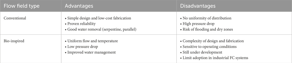
Table 3. Advanced design for the cooling channels in bipolar plates of PEMFC.
2.2 Coolant channels in FFP
The design of coolant channels in FFPs involves a balance between maximizing heat removal and minimizing the disruption to fuel and oxidant distribution across the FC. These channels are not merely conduits for coolant flow; they are a critical part of the FCs architecture including their size, shape and flow path, influencing everything from the FC’s thermal and hydraulic performance to its electrical efficiency and material durability. The coolant fluid is typically water, glycol mixture or a base fluid with nanoparticles; the last one gets more attention recently from researcher to develop (Li C. et al., 2022; Afshari et al., 2022; Song et al., 2022; Hashmi, 2010). Different techniques for the cooling channels are presented in Figure 8. The most efficient examples of the cooling system are summarized in Table 4.
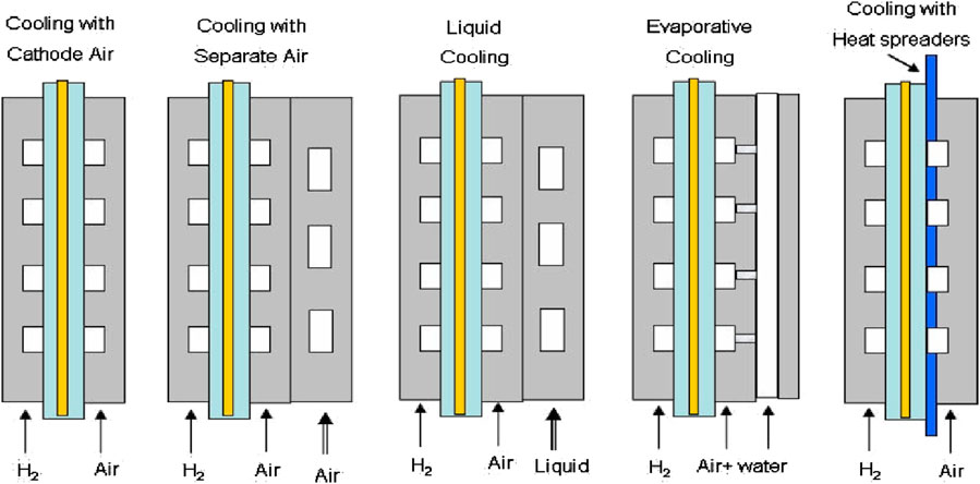
Figure 8. PEMFC cooling techniques (from (Hashmi, 2010)).
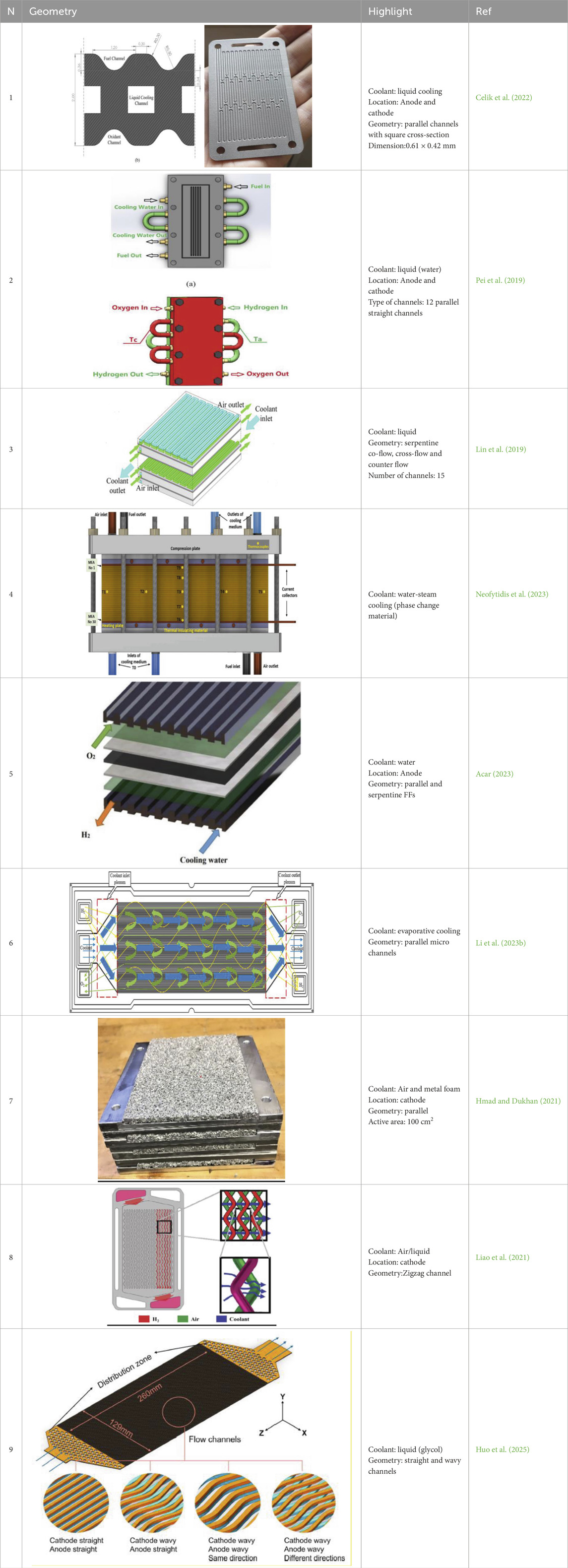
Table 4. Advanced design for the cooling channels in bipolar plates of PEMFC.
The materials, geometry and operating conditions of the cooling systems for PEMFC stacks given in Table 4 are briefly summarized below. Their benefits and limitations are discussed. Celik et al. (Celik et al., 2022) (N1 in Table 4) investigated the use of titanium bipolar plates created through additive manufacturing for use in PEMFC, particularly in electric vehicles. The study employs active cooling methods using these advanced titanium plates. The main advantages include improved durability, corrosion resistance, and mechanical strength of the titanium plates, which enhance the overall performance and longevity of the PEMFCs. The results show that the titanium bipolar plates achieved a peak power density of 639 mW cm-2.
Pei et al. (2019) (N2 in Table 4) investigated the use of separated coolant flow channels for the anode and cathode of PEMFCs. This cooling approach allows for independent temperature control on both sides, improving overall thermal management. The main advantages include enhanced temperature uniformity and reduced thermal stresses, leading to more stable FC operation. The study found that this design significantly increased power density by 13% compared to conventional single-loop cooling systems, and improved water management by reducing the risk of flooding.
Lin et al. (2019) (N3 in Table 4) optimized both the configuration and operating parameters of liquid-cooled PEMFC stack. The study focused on liquid cooling as the primary cooling method, which enhanced thermal management and operational stability. The main advantages of this approach included improved temperature control and temperature uniformity over the MEA, which are critical for the efficient operation of PEMFCs. The results show that the optimized configurations and parameters led to a significant increase in power density by 9.5%.
Neofytidis et al. (2023) (N4 in Table 4) explored the implementation of a two-phase liquid cooling system for high-temperature PEMFC. This cooling method leverages phase change (water-steam) to manage thermal loads effectively. The advantages include enhanced thermal management and reduced complexity due to the pumpless design. The study found that the innovative cooling system improved power density to 0.18 W/cm2 at 180°C.
Acar (2023) (N5 in Table 4) investigated the thermal performance of PEMFC using serpentine and straight coolant flow channels. The study utilize. numerical modelling to examine the effects of different coolant flow directions on heat removal efficiency. The results showed that optimizing the coolant flow direction can significantly enhance thermal performance, with the straight flow channels improving temperature uniformity by 55.45% compared to the serpentine FF.
Li Y. et al. (2023) (N6 in Table 4) investigated the thermal management of PEMFC using various micro-channel configurations with flow boiling. The study focused on experimental analysis of three different micro-channel designs to evaluate their effectiveness in cooling. The advantages of using flow boiling in micro-channels include higher heat transfer coefficients and better temperature uniformity compared to traditional single-phase cooling methods. The results demonstrated that the optimal micro-channel configuration significantly reduced the maximum temperature by up to 15%.
Hmad and Dukhan (2021) (N7 in Table 4) investigated the use of air cooling combined with open-cell metal foam in PEMFC stacks. The study involved both numerical simulations and experimental testing to assess the efficacy of this cooling method. The metal foam, with a pore size of 0.65 mm and 60% porosity after compression, enhanced heat transfer and temperature uniformity. The results showed that employing metal foam for air cooling significantly improved thermal management compared to traditional liquid cooling. Specifically, the metal foam increased the efficiency of heat removal, maintaining lower and more uniform temperatures across the FC stack.
Liao et al. (2021) (N8 in Table 4) investigated zigzag-shaped channels for both reactant and cooling fluid flow management. The study highlighted the significant impact of these channels on enhancing the uniformity of reactant distribution, achieving a more uniform temperature distribution, and improving overall performance despite an increase in pressure drop. Key findings showed that zigzag channels enhance mass transfer, leading to a 12% improvement in current density distribution and a 15% reduction in temperature variance across the FC. Additionally, the zigzag design resulted in a 20% increase in pressure drop.
Huo et al. (2025) (N9 in Table 4) proposed a novel cooling strategy for large-scale PEMFCs using two models. A single heat transfer model evaluated four coolant channel types. Straightandwavy and different wavy channels showed better temperature uniformity, but higher pressure drops compared to the straight channels. The straightandstraight and straightandwavy channels had lower parasitic power but less uniform flow. A combination of the 3D and 1D flow models with a new Linearly Varying Temperature Convection (LVTC) method replaced complex channel geometry. LVTC achieved high accuracy with only 1.126% voltage deviation, offering an efficient tool for PEMFC thermal simulation and cooling design.
Therefore, modifications in the shape (waved, zigzag, etc.) and location of the cooling channels can significantly increase the overall efficiency (by 10%–13%) and enhance the uniformity of temperature distribution (by 15%–55%), which is essential for FC technology. A successful combination of proper modifications in both FFs and cooling channels to achieve a synergetic effect remains a key challenge for future development. Moreover, bridging the gap between CFD-based predictions and experimental validations remains a major obstacle, especially in large-area FC systems where multi-physics interactions are complex. In this context, Huo et al. (Huo et al., 2024) demonstrated that digitally assisted structural design could provide a reliable link between simulation and realistic performance, enabling accurate optimization of flow and cooling architectures in large-scale PEMFCs.
3 Materials and manufacturing for FFPs in PEMFCs
There are several alternative ways in which FFPs can be made for PEMFC. All of them can be produced by materials selection, followed by shaping or forming the plate. Afterwards, machining or etching is done to create the gas flow channels, and finally the surface is treated to achieve high hydrophobicity and longevity of the material. Among these characteristics, include easy electrical conductivity, lightweight, and corrosion resistance, which are proper to graphite and many types of polymers. They include methods of injection molding, hot pressing, and stamping used to form the plates in PEMFC (Wilberforce et al., 2017; Cooper, 2004; Ijaodola et al., 2018). Among other methods related to FFP manufacture, are additive production, 3D printing, CNC milling, laser cutting and electroforming.
The choice of manufacturing technique depends on.
1) Cost efficiency: Additive manufacturing through electrochemical deposition ensures long-term cost efficiency due to reduced material wastage and a means to incorporate the design of complex shapes without a proportional increase in production costs. However, the cost for set up and materials at the preliminary stage could be more than the costs for simplified FFs.
2) Design complexity: Different manufacturing techniques allow for varying levels of complexity in design, the complexity of FFPs depends on channels dimensions, integration of features and material compatibility.
3) Scalability: Traditional processes such as compression molding are most scalable even today for high on volumes of products, although new developments that are becoming a reality in the AM realm may soon equalize the differences (Karimi et al., 2012), (Yoon et al., 2008), (Mehta and Cooper, 2003), (Tang et al., 2021).
A classification of materials for FFPs is presented in Figure 9. The developmental target for PEMFC technology and FFPs according to the U.S department of energy, are presented in Table 5 (Tang et al., 2021). Based on the given literature review and Tables 1–4, the overview of materials and manufacturing technologies is given in Table 6.
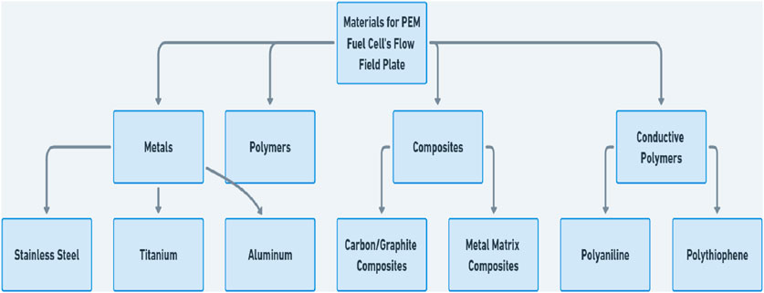
Figure 9. Classification of materials for PEMFC FFPs (from (US Department of Energy, 2016b)).

Table 5. Technical indicators of bipolar plate according to the U.S department of energy.
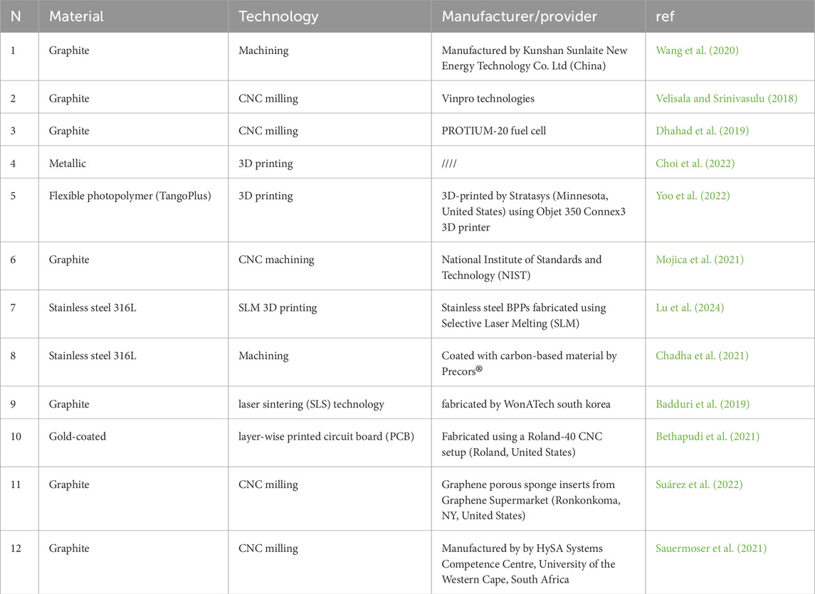
Table 6. Materials and fabrication techniques for FFP.
The manufacturing cost of FFP is one of the main criteria in order to select an appropriate method for fabrication. Table 7 gives an overview of the cost incurred for different types of FFP fabrication. The Table shown, the costs has been decreased significantly during the past decade. This is mostly credited to the continued improvement in 3D printing technology, together with the advances in other means of production. The use and development of these methods promise good opportunities for cost reduction, as well as for additional flexibility and increased accuracy in the manufacture of the FFP conditions, which probably have to be considered in their future design.
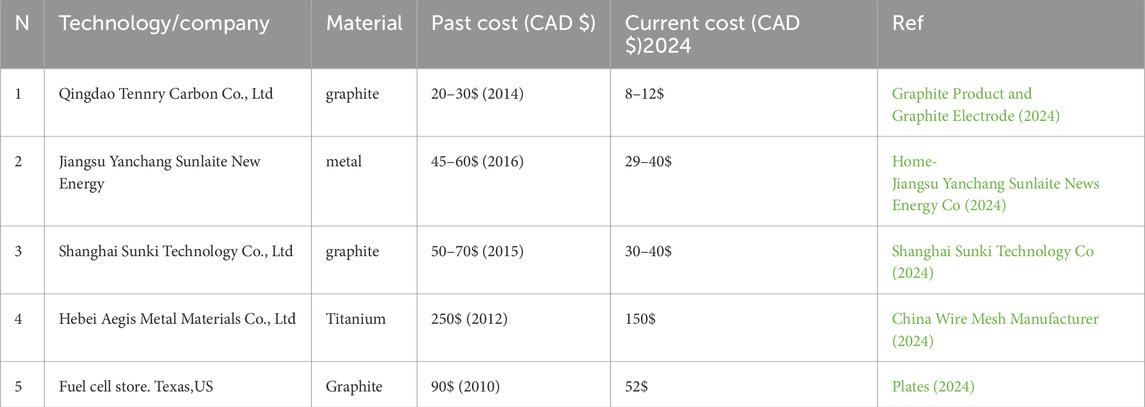
Table 7. Fabrication costs of FFP’s with 5 × 5 = 25 cm2 area in 2024.
The declining cost trend of FFPs shown in Table 7 aligns with DOE reports, which indicate a significant reduction in bipolar plate fabrication costs from over $800/kW in the early 2000s to approximately $20/kW in 2016 for high-volume automotive production (U.S. Department of Energy, 2016a). a trend largely attributable to increased competitiveness among manufacturers. This competitive landscape has spurred innovations in manufacturing processes and material utilisation, driving down production costs. Additionally, the entrance of new market players and advancements in technology have further intensified competition.
4 Conclusion and recommendations
In this review, we undertook a comprehensive analysis of the design and manufacturing processes associated with FFPs and cooling systems in PEMFCs. Several key observations emerged.
1. Bio-inspired designs: The emergence of bio-inspired designs stands out as a notable advancement, offering substantial promise in enhancing PEMFC performance. These designs, which are inspired by the intricate and efficient patterns found in nature that have been refined through millions of years of evolution, show significant potential in emulating the effectiveness of natural systems. This insight points towards a promising pathway for future developments in FFP technology. The potential utility of bio-inspired FFPs in industrial applications is significant. However, their widespread adoption is contingent upon achieving cost competitiveness with conventional FFP designs. If the manufacturing costs of bio-inspired FFP can be reduced to match those of traditional designs and materials, their implementation in the industry will likely become more viable and advantageous.
2. Water management: The aspect of water management within the bio-inspired frameworks deserves focused exploration. Given the paramount importance of effective water handling for the optimal functionality of PEMFCs, bio-inspired designs introduce innovative approaches to this challenge. The complex patterns modelled after natural distributed networks (lungs, blood vessels, nervous cells, plant leaves, roots and branches, etc.) present a fertile ground for further investigation, potentially revealing methods to enhance FC durability, operational efficiency, and overall reliability.
3. Coolant channels: In addition to the significant impact of coolant channels on the performance of PEMFC, they also play critical role in reducing the overall weight of FFPs and consequently the FC stack. The design and optimization of these channels are promising, as their dimensions and size can pose substantial challenges during the manufacturing process. However, these benefits come with inherent complexity of manufacturing, where precise control over channel dimensions becomes crucial. This complexity can lead to increased costs and production difficulties, making it essential for future research to focus on innovative design solutions that balance performance with manufacturability.
4. Manufacturing advancements: Progress in manufacturing technology, particularly additive manufacturing, is opening new avenues for producing intricate FFPs. Additive manufacturing (3D printing) allows the construction of complex channel geometries and internal structures that would be impractical with traditional machining. This enables rapid prototyping and small-batch production of bio-inspired designs or integrated coolant channels without the need for expensive tooling. However, current 3D printing methods can be slow and costly for mass production, and material choices (metals vs polymers) must ensure sufficient conductivity and durability for FC use. To bridge this gap, research is advancing in high-speed metal printing, multi-material printing, and post-processing techniques (such as coating printed plates for corrosion protection. The future outlook is a convergence of these approaches: hybrid manufacturing routes that exploit 3D printing’s design freedom and traditional methods’ efficiency, leading to cost-effective production of next-generation FFPs with minimal geometric constraints.
5. Sustainable material: Material choices for FFPs are increasingly driven by sustainability as well as performance. While graphite offers excellent corrosion resistance, it is heavy, brittle, and costly to machines. Recent trends favour metals like stainless steel, aluminium, and titanium for their strength, conductivity, and recyclability, especially stainless steel, which is thin, durable, and 100% recyclable. However, metallic plates require protective coatings to prevent corrosion, though recent innovations are reducing reliance on scarce materials like gold. Polymer–carbon composites also offer low-cost, mouldable options with potential for recyclability when thermoplastic binders are used. Moving forward, material strategies should adopt a full life-cycle perspective - prioritizing recyclability, durability, and ease of disassembly - to support a more sustainable and circular PEMFC industry.
Author contributions
AM: Conceptualization, Writing – original draft. NK: Methodology, Writing – original draft, Writing – review and editing. TA: Formal Analysis, Supervision, Writing – review and editing. MK: Writing – review and editing, Formal analysis, Funding acquisition, Visualization.
Funding
The author(s) declare that financial support was received for the research and/or publication of this article. Research was funded by POB Energy of Warsaw University of Technology within the Excellence Initiative: Research University (IDUB) program (the ENERGYTECHDEMO grant). The authors gratefully acknowledge the funding and resources provided, which enabled the successful completion of this research.
Conflict of interest
The authors declare that the research was conducted in the absence of any commercial or financial relationships that could be construed as a potential conflict of interest.
Generative AI statement
The author(s) declare that no Generative AI was used in the creation of this manuscript.
Publisher’s note
All claims expressed in this article are solely those of the authors and do not necessarily represent those of their affiliated organizations, or those of the publisher, the editors and the reviewers. Any product that may be evaluated in this article, or claim that may be made by its manufacturer, is not guaranteed or endorsed by the publisher.
References
Acar, M. C. (2023). Modeling the influence of coolant flow directions on thermal performance of PEM fuel cell cooling plates with serpentine and straight flow channels. Thermochim. Acta 726, 179560. doi:10.1016/j.tca.2023.179560
Afshari, E., Nabi, J., and Atyabi, S. A. (2022). “Configuration of proton exchange membrane fuel cell gas and cooling flow fields,” in PEM fuel cells. Fundamentals, advanced technologies, and practical application (Elsevier), 429–463.
Badduri, S. R., Srinivasulu, G. N., and Rao, S. S. (2019). Experimental analysis of PEM fuel cell performance using lung channel design bipolar plate. Intern. J. Green Energy 16 (15), 1591–1601. doi:10.1080/15435075.2019.1677238
Bethapudi, V. S., Hack, J., Hinds, G., Shearing, P. R., Brett, D. J. L., and Coppens, M. O. (2021). Electro-thermal mapping of polymer electrolyte membrane fuel cells with a fractal flow-field. Energy Conversion&Management 250, 114924. doi:10.1016/j.enconman.2021.114924
Bethapudi, V. S., Hack, J., Trogadas, P., Cho, J. I. S., Rasha, L., Hinds, G., et al. (2019). A lung-inspired printed circuit board polymer electrolyte fuel cell. Energy Conversion&Management 202, 112198. doi:10.1016/j.enconman.2019.112198
Cai, G., Liang, Y., Liu, Z., and Liu, W. (2020). Design and optimization of bio-inspired wave-like channel for a PEM fuel cell applying genetic algorithm. Energy 192, 116670. doi:10.1016/j.energy.2019.116670
Cao, T.-F., Lin, H., Chen, L., He, Y.-L., and Tao, W.-Q. (2013). Numerical investigation of the coupled water and thermal management in PEM fuel cell. Appl. Energy 112, 1115–1125. doi:10.1016/j.apenergy.2013.02.031
Celik, S., Timurkutluk, B., Aydin, U., and Yagiz, M. (2022). Development of titanium bipolar plates fabricated by additive manufacturing for PEM fuel cells in electric vehicles. Intern. J. Hydrogen Energy 47 (89), 37956–37966. doi:10.1016/j.ijhydene.2022.08.282
Chadha, K., Martemianov, S., and Thomas, A. (2021). Study of new flow field geometries to enhance water redistribution and pressure head losses reduction within PEM fuel cell. Intern. J. Hydrogen Energy 46 (10), 7489–7501. doi:10.1016/j.ijhydene.2020.11.194
Chen, H., Xu, S., Pei, P., Qu, B., and Zhang, T. (2019). Mechanism analysis of starvation in PEMFC based on external characteristics. Intern. J. Hydrogen Energy 44 (11), 5437–5446. doi:10.1016/j.ijhydene.2018.11.135
Chen, X., Chai, F., Hu, S., Tan, J., Luo, L., Xie, H., et al. (2023). Design of PEMFC bipolar plate cooling flow field based on fractal theory. Energy Convers. and Manag. 20, 100445. doi:10.1016/j.ecmx.2023.100445
China Wire Mesh Manufacturer (2024). Wire mesh filter, sintered mesh filter supplier. Hebei, China: Hebei aegis metal materials Co., Ltd. Available online at: https://aegismetal.en.made-in-china.com.
Choi, S. H., Kang, D. G., Lim, I. S., Lim, H. S., Park, C., and Kim, M. S. (2022). Experimental study on non-uniform arrangement of 3D printed structure for cathodic flow channel in PEMFC. Intern. J. Hydrogen Energy 47 (2), 1192–1201. doi:10.1016/j.ijhydene.2021.10.059
Cooper, J. S. (2004). Design analysis of PEMFC bipolar plates considering stack manufacturing and environment impact. J. Power Sources 129 (2), 152–169. doi:10.1016/j.jpowsour.2003.11.037
Dhahad, H. A., Alawee, W. H., and Hassan, A. K. (2019). Experimental study of the effect of flow field design to PEM fuel cells performance. Renew. Energy Focus 30, 71–77. doi:10.1016/j.ref.2019.05.002
Dihrab, S. S., Sopian, K., Alghoul, M. A., and Sulaiman, M. Y. (2009). Review of the membrane and bipolar plates materials for conventional and unitized regenerative fuel cells. Renew. Sustain. Energy Rev 13 (6-7), 1663–1668. doi:10.1016/j.rser.2008.09.029
Dong, P., Xie, G., and Ni, M. (2021). Improved energy performance of a PEM fuel cell by introducing discontinuous S-shaped and crescent ribs into flowing channels. Energy 222, 119920. doi:10.1016/j.energy.2021.119920
Ebrahimi, M., Kujawski, W., Fatyeyeva, and K., and Kujawa, J. (2021). A review on ionic liquids-based membranes for middle and high temperature polymer electrolyte membrane fuel cells (PEM FCs). Int. J. Mol. Sci. 22, 5430. doi:10.3390/ijms22115430
Fan, W., Zhao, T., Jiang, K., Sun, L., Jia, S., Wu, Q., et al. (2022). Plant vs. animal prototype for designing bio-inspired pemfc flow fields: corn veins or Murray’s law? J. Bionic Engin. 19 (3), 761–776. doi:10.1007/s42235-022-00174-4
Ghadhban, S. A., Alawee, W. H., and Dhahad, H. A. (2021). Study effects of bio-inspired flow filed design on polymer electrolyte membrane fuel cell performance. Case Stud. Therm. Engin 24, 100841. doi:10.1016/j.csite.2021.100841
Graphite Product, Graphite Electrode (2024). Special type graphite. Henan, China: Carburant. Available online at: https://www.tennry.com/.
Hamilton, P. J., and Pollet, B. G. (2010). Polymer electrolyte membrane fuel cell (PEMFC) flow field plate: design, materials and characterisation. Fuel Cells 10 (4), 489–509. doi:10.1002/fuce.201000033
Hashmi, S. M. H. (2010). Cooling Strategies for PEM FC Stacks. Doctoral dissertation, Helmut-Schmidt-Universität. Hamburg, Germany: Universität der Bundeswehr Hamburg.
Hermann, A., Chaudhuri, T., and Spagnol, P. (2005). Bipolar plates for PEM fuel cells: a review. Intern. J. Hydrogen Energy 30 (12), 1297–1302. doi:10.1016/j.ijhydene.2005.04.016
Hmad, A. A., and Dukhan, N. (2021). Cooling design for PEM fuel-cell stacks employing air and metal foam: simulation and experiment. Energies 14 (9), 2687. doi:10.3390/en14092687
Home-Jiangsu Yanchang Sunlaite News Energy Co., Ltd. (2024). Jiangsu, China: Home-Jiangsu Yanchang Sunlaite News Energy Co., Ltd. Available online at: https://en.sunlaite.com/.
Hu, Ch., Zhao, Y., Zhang, Z., Zhang, H., and Chen, D. (2023). Optimization of flow field structure for proton exchange membrane fuel cell stack by multi-physics coupling simulation. Intern. J. electrochem. Sci. 18 (7), 100195. doi:10.1016/j.ijoes.2023.100195
Huang, H., Lei, H., Liu, M., Wang, T., Li, C., Guo, X., et al. (2020). Effect of superior mesenteric artery branch structure-based flow field on PEMFC performance. Energy Convers. and Manag. 226, 113546. doi:10.1016/j.enconman.2020.113546
Huo, W., Fan, L., Xu, Y., Benbouzid, M., Xu, W., Gao, F., et al. (2025). Digitally-assisted structure design of a large-size proton exchange membrane fuel cell. Energy and Environ. Sci. 18 (2), 631–644. doi:10.1039/d4ee04713c
Huo, W., Liu, B., Xu, W., Xie, B., Fan, L., Benbouzid, M., et al. (2024). High precision and efficient simulation of large-size proton exchange membrane fuel cells incorporated with a novel alternative cooling method. Intern. J. Heat. &Mass Transf. 230, 125780. doi:10.1016/j.ijheatmasstransfer.2024.125780
Ijaodola, O., Ogungbemi, E., Khatib, F. N., Wilberforce, T., Ramadan, M., El Hassan, Z., et al. (2018). Evaluating the effect of metal bipolar plate coating on the performance of proton exchange membrane fuel cells. Energies 11 (11), 3203. doi:10.3390/en11113203
Jang, J. Y., Cheng, C. H., Liao, W. T., Huang, Y. X., and Tsai, Y. C. (2012). Experimental and numerical study of proton exchange membrane fuel cell with spiral flow channels. Appl. Energy 99, 67–79. doi:10.1016/j.apenergy.2012.04.011
Kandlikar, S. G. (2008). Microscale and macroscale aspects of water management challenges in PEM fuel cells. Heat. Transf. Engin 29 (7), 575–587. doi:10.1080/01457630801922246
Kang, H. C., Jum, K. M., and Sohn, Y. J. (2019). Performance of unit PEM fuel cells with a leaf-vein-simulating flow field-patterned bipolar plate. Intern. J. Hydrogen Energy 44 (43), 24036–24042. doi:10.1016/j.ijhydene.2019.07.120
Karimi, S., Fraser, N., Roberts, B., and Foulkes, F. R. (2012). A review of metallic bipolar plates for proton exchange membrane fuel cells: materials and fabrication methods. Adv. Mater. Sci. and Engin 2012, 1–22. doi:10.1155/2012/828070
Ke, Y., Zhang, B., Yuan, W., Bai, Y., Zhao, Y., Liu, Z. A., et al. (2023). Performance enhancement of proton exchange membrane fuel cells with bio-inspired gear-shaped flow channels. Chem. Engin. J. 474, 145870. doi:10.1016/j.cej.2023.145870
Kizilova, N. (2004). Computational approach to optimal transport network construction in biomechanics. Lecture Notes in Computer Sci. 3044, 476–485.
Li, C., Xu, X., Hu, H., Mei, N., and Yang, Y. (2022b). Numerical investigation into the effect of structural parameters of parallel flow field with cooling channels on fuel cell performance. J. Electrochem. Energy Convers. Storage 19 (1), 010903. doi:10.1115/1.4050368
Li, N., Wang, W., Xu, R., Zhang, J., and Xu, H. (2023a). Design of a novel nautilus bionic flow field for proton exchange membrane fuel cell by analyzing performance. Intern. J.Heat and Mass Transf. 200, 123517. doi:10.1016/j.ijheatmasstransfer.2022.123517
Li, Y., Bi, J., Tang, M., and Lu, G. (2022a). Snowflake bionic flow channel design to optimize the pressure drop and flow uniform of proton exchange membrane fuel cells. Micromachines 13 (5), 665. doi:10.3390/mi13050665
Li, Y., He, J., Luo, X., Liang, Y., Zhang, Y., Yang, Z., et al. (2023b). Experimental study on flow boiling-based micro-channel configurations for the PEMFC cooling. Therm. Sci. Engin. Prog. 46, 102210. doi:10.1016/j.tsep.2023.102210
Liao, Z., Wei, L., Dafalla, A. M., Guo, J., and Jiang, F. (2021). Analysis of the impact of flow field arrangement on the performance of PEMFC with zigzag-shaped channels. Intern. J. Heat and Mass Transf. 181, 121900. doi:10.1016/j.ijheatmasstransfer.2021.121900
Lim, B. H., Majlan, E. H., Daud, W. R. W., Husaini, T., and Rosli, M. I. (2016). Effects of flow field design on water management and reactant distribution in PEMFC: a review. Ionics 22, 301–316. doi:10.1007/s11581-016-1644-y
Lin, C., Yan, X., Wei, G., Ke, C., Shen, S., and Zhang, J. (2019). Optimization of configurations and cathode operating parameters on liquid-cooled proton exchange membrane fuel cell stacks by orthogonal method. Appl. Energy 253, 113496. doi:10.1016/j.apenergy.2019.113496
Lu, K., Zhang, J., Ding, H., Wang, Z., and Pan, X. (2024). Numerical and experimental investigation of 3D flow field bipolar plates for PEMFCs by metal 3D printing. Fuel 357, 129699. doi:10.1016/j.fuel.2023.129699
Luo, S., Zhang, Y., Zhang, J., and Xu, J. (2020). A user biology preference prediction model based on the perceptual evaluations of designers for biologically inspired design. Symmetry 12 (11), 1860. doi:10.3390/sym12111860
Madhav, D., Wang, J., Keloth, R., Mus, J., Buysschaert, F., and Vandeginste, V. (2024). A review of proton exchange membrane degradation pathways, mechanisms, and mitigation strategies in a fuel cell. Energies 17 (5), 998. doi:10.3390/en17050998
Marappan, M., Palaniswamy, K., Velumani, T., Chul, K. B., Velayutham, R., Shivakumar, P., et al. (2021). Performance studies of proton exchange membrane fuel cells with different flow field designs–review. Chem. Rec. 21 (4), 663–714. doi:10.1002/tcr.202000138
Mehta, V., and Cooper, J. S. (2003). Review and analysis of PEM fuel cell design and manufacturing. J. Power Sources 114 (1), 32–53. doi:10.1016/s0378-7753(02)00542-6
Mekhilef, S., Saidur, R., and Safari, A. (2012). Comparative study of different fuel cell technologies. Renew. Sustain. Energy Rev. 16 (1), 981–989. doi:10.1016/j.rser.2011.09.020
Merdjani, A., Kizilova, N., and Awotwe, T. W. (2024). Optimizing performance in PEM fuel cells: a simulation study of T-junction fractal flow field plate. Preprint. doi:10.2139/ssrn.5011186
Mojica, F., Rahman, M. A., Sarker, M., Hussey, D. S., Jacobson, D. L., LaManna, J. M., et al. (2021). Study of converging-diverging channel induced convective mass transport in a proton exchange membrane fuel cell. Energy Convers. and Manag. 237, 114095. doi:10.1016/j.enconman.2021.114095
Molina, D., Poyatos, J., Ser, J. D., García, S., Hussain, A., and Herrera, F. (2020). Comprehensive taxonomies of nature-and bio-inspired optimization: inspiration versus algorithmic behavior, critical analysis recommendations. Cogn. Comput. 12, 897–939. doi:10.1007/s12559-020-09730-8
Neofytidis, C., Paloukis, F., Athanasopoulos, N., Neophytides, S. G., and Daletou, M. K. (2023). Efficient high temperature PEMFC metallic stack with innovative two-phase liquid cooling. Energy Convers. and Manag. 283, 116944. doi:10.1016/j.enconman.2023.116944
Nöst, M., Doppler, Ch., Klell, M., and Trattner, A. (2018). “Thermal management of PEM fuel cells in electric vehicles,” in Comprehensive energy management-safe adaptation, predictive control and thermal management (Springer), 93–112.
Obayopo, S. O., Bello-Ochende, T., and Meyer, J. P. (2012). Modelling and optimization of reactant gas transport in a PEM fuel cell with a transverse pin fin insert in channel flow. Intern. J. Hydrogen Energy 37 (13), 10286–10298. doi:10.1016/j.ijhydene.2012.03.150
Olabi, A. G., Wilberforce, T., and Abdelkareem, M. A. (2021). Fuel cell application in the automotive industry and future perspective. Energy 214, 118955. doi:10.1016/j.energy.2020.118955
Pan, Y., Ruan, H., Wu, B., Regmi, Y. N., Wang, H., and Brandon, N. P. (2024). A machine learning driven 3D+ 1D model for efficient characterization of proton exchange membrane fuel cells. Energy AI 17, 100397. doi:10.1016/j.egyai.2024.100397
Pei, H., Meng, K., Chang, H., Zhang, Y., Shen, J., Tu, Z., et al. (2019). Performance improvement in a proton exchange membrane fuel cell with separated coolant flow channels in the anode and cathode. Energy Convers. and Manag. 187, 76–82. doi:10.1016/j.enconman.2019.03.020
Pentelovitch, N., and Nagel, J. K. (2022). Understanding the use of bio-inspired design tools by industry professionals. Biomimetics 7 (2), 63. doi:10.3390/biomimetics7020063
Plates (2024). Fuel cell store. Available online at: https://www.fuelcellstore.com/fuel-cell-components/plates.
Ramin, F., Sadeghifar, H., and Torkavannejad, A. (2019). Flow field plates with trap-shape channels to enhance power density of polymer electrolyte membrane fuel cells. Intern. J. Heat and Mass Transf. 129, 1151–1160. doi:10.1016/j.ijheatmasstransfer.2018.10.050
Ruan, H., Wu, Ch., Liu, Sh., and Chen, T. (2016). Design and simulation of novel flow field plate geometry for proton exchange membrane fuel cells. Heat and Mass Transf. 52, 2167–2176. doi:10.1007/s00231-015-1737-6
Sauermoser, M., Kizilova, N., Pollet, B. G., and Kjelstrup, S. (2020). Flow field patterns for proton exchange membrane fuel cells. Front. Energy Res. 8, 13. doi:10.3389/fenrg.2020.00013
Sauermoser, M., Pollet, B. G., Kizilova, N., and Kjelstrup, S. (2021). Scaling factors for channel width variations in tree-like flow field patterns for polymer electrolyte membrane fuel cells - an experimental study. Intern. J. Hydrogen Energy 46 (37), 19554–19568. doi:10.1016/j.ijhydene.2021.03.102
Sebbani, I., Ettouhami, M. K., and Boulakhbar, M. (2025). Fuel Cells: a technical, environmental, and economic outlook. Clean. Energy Syst. 10, 100168. doi:10.1016/j.cles.2024.100168
Shaigan, N., Yuan, X.-Z., Girard, F., Fatih, K., and Robertson, M. (2021). Standardized testing framework for quality control of fuel cell bipolar plates. J. Power Sources 482, 228972. doi:10.1016/j.jpowsour.2020.228972
Shanghai Sunki Technology Co., Ltd. (2024). Shanghai, China: Shanghai Sunki Technology Co., Ltd. Available online at: https://www.sh-sunki.com.
D. Shekhawat, J. J. Spivey, and D. A. Berry (2011). Fuel cells: technologies for fuel processing (Elsevier).
Sierra, J. M., Figueroa-Ramírez, S. J., Díaz, S. E., Vargas, J., and Sebastian, P. J. (2014). Numerical evaluation of a PEM fuel cell with conventional flow fields adapted to tubular plates. Intern. J. Hydrogen Energy 39 (29), 16694–16705. doi:10.1016/j.ijhydene.2014.04.078
Song, J., Huang, Y., Liu, Y., Ma, Z., Chen, L., Li, T., et al. (2022). Numerical investigation and optimization of cooling flow field design for proton exchange membrane fuel cell. Energies 15 (7), 2609. doi:10.3390/en15072609
Song, P., Qiao, G., Hu, X., Xia, X., Xu, G., and Deng, Z. (2021). “Current status and research progress of bipolar plates for proton exchange membrane fuel cells,” in 2021 international conference on power system technology (POWERCON) (Wuhan, China), 202–208.
Steele, B. C. H., and Heinzel, A. (2001). Materials for fuel-cell technologies. Nature 414 (6861), 345–352. doi:10.1038/35104620
Suárez, C., Iranzo, A., Toharias, B., and Rosa, F. (2022). Experimental and numerical Investigation on the design of a bioinspired PEM fuel cell. Energy 257, 124799. doi:10.1016/j.energy.2022.124799
Tang, A., Crisci, L., Bonville, L., and Jankovic, J. (2021). An overview of bipolar plates in proton exchange membrane fuel cells. J. Renew. and Sustain. Energy 13 (2). doi:10.1063/5.0031447
Tiss, F., Chouikh, R., and Guizani, A. (2014). A numerical investigation of reactant transport in a PEM fuel cell with partially blocked gas channels. Energy Convers. and Manag. 80, 32–38. doi:10.1016/j.enconman.2013.12.063
U.S. Department of Energy (2016a). Hydrogen and Fuel Cells Program: 2016 Annual Merit Review and Peer Evaluation Report. Washington, DC: U.S. Department of Energy. Available online at: https://www.nrel.gov/docs/fy17osti/66805.pdf.
US Department of Energy (2016b). The fuel cell technologies office multi-year research. Dev. demonstration plan. Available online at: https://www.energy.gov/.
Velisala, V., and Srinivasulu, G. N. (2018). Numerical simulation and experimental comparison of single, double and triple serpentine flow channel configuration on performance of a PEM fuel cell. Arab. J. Sci. Eng. 43, 1225–1234. doi:10.1007/s13369-017-2813-7
Vijayakrishnan, M. K., Palaniswamy, K., Ramasamy, J., Kumaresan, T., Manoharan, K., Raj Rajagopal, T. K., et al. (2020). Numerical and experimental investigation on 25 cm2 and 100 cm2 PEMFC with novel sinuous flow field for effective water removal and enhanced performance. Intern. J. Hydrogen Energy 45 (13), 7848–7862. doi:10.1016/j.ijhydene.2019.05.205
Wan, Zh., Quan, W., Yang, Ch., Yan, H., Chen, X., Huang, T., et al. (2020). Optimal design of a novel M-like channel in bipolar plates of proton exchange membrane fuel cell based on minimum entropy generation. Energy Convers. and Manag. 205, 112386. doi:10.1016/j.enconman.2019.112386
Wang, H. H., and Deng, X. (2022). The role of fluid intelligence in creativity: the case of bio-inspired design. Think. Ski. and Creativity 45, 101059. doi:10.1016/j.tsc.2022.101059
Wang, Sh., and Jiang, S. P. (2017). Prospects of fuel cell technologies. Natl. Sci. Rev. 4 (2), 163–166. doi:10.1093/nsr/nww099
Wang, X., Qin, Y., Wu, Sh., Shangguan, X., Zhang, J., and Yin, Y. (2020). Numerical and experimental investigation of baffle plate arrangement on proton exchange membrane fuel cell performance. J. Power Sources 457, 228034. doi:10.1016/j.jpowsour.2020.228034
Wang, Y., Chen, K. S., Mishler, J., Cho, S.Ch, and Adroher, X. C. (2011). A review of polymer electrolyte membrane fuel cells: technology, applications, and needs on fundamental research. Appl. Energy 88 (4), 981–1007. doi:10.1016/j.apenergy.2010.09.030
Wang, Y., Si, C., Qin, Y., Wang, X., Fan, Y., and Gao, Y. (2021). Bio-inspired design of an auxiliary fishbone-shaped cathode flow field pattern for polymer electrolyte membrane fuel cells. Energy Convers. Manag. 227, 113588. doi:10.1016/j.enconman.2020.113588
Wilberforce, T., Ijaodola, O., Ogungbemi, E., Khatib, F. N., and Olabi, A. G. (2017). “Computational Fluid Dynamic simulation and modelling (CFX) of flow plate in PEM fuel cell using aluminum open cellular foam material,” in IEEE Texas power and energy conference (TPEC). IEEE.
Xiong, K., Wu, W., Wang, S., and Zhang, L. (2021). Modeling, design, materials and fabrication of bipolar plates for proton exchange membrane fuel cell: a review. Appl. Energy 301, 117443. doi:10.1016/j.apenergy.2021.117443
Xu, X., Zhang, L., Wang, S., Han, D., You, S., and Zhou, J. (2024). Numerical and experimental analyses of a novel type PEMFC coolant channel. Intern. J. Hydrogen Energy 49, 652–673. doi:10.1016/j.ijhydene.2023.08.355
Yan, H., Zhang, W., Qu, Z., and Chen, N. (2023). Flow field plate of polymer electrolyte membrane fuel cells: a review. J. Renew. and Sustain. Energy 15 (1). doi:10.1063/5.0124224
Yao, J., Yan, F., and Pei, X. (2022). Design and analysis of spider bionic flow field for proton exchange membrane fuel cell. J. Electrochem. Sci. and Technol. 14 (1), 38–50. doi:10.33961/jecst.2022.00479
Yeetsorn, R. (2010). “Development of electrically conductive thermoplastic composites for bipolar plate application in polymer electrolyte membrane fuel cell,” in PhD thesis. Department of chemical engineering. Waterloo, ON, Canada: University of Waterloo.
Yoo, H., Kwon, O., Kim, J., Cha, H., Kim, H., Choi, H., et al. (2022). 3D-printed flexible flow-field plates for bendable polymer electrolyte membrane fuel cells. J. Power Sources 532, 231273. doi:10.1016/j.jpowsour.2022.231273
Yoon, W., Huang, X., Fazzino, P., Reifsnider, K. L., and Akkaoui, M. A. (2008). Evaluation of coated metallic bipolar plates for polymer electrolyte membrane fuel cells. J. Power Sources 179 (1), 265–273. doi:10.1016/j.jpowsour.2007.12.034
Zhang, C., Zhou, W., Zhang, L., Chan, S. H., and Wang, Y. (2015). An experimental study on anode water management in high temperature PEM fuel cell. Intern. J. Hydrogen Energy 40 (13), 4666–4672. doi:10.1016/j.ijhydene.2015.02.037
Zhang, Y., and Tu, Z. (2024). Flow field design of the bipolar plates in polymer electrolyte membrane fuel cell: problem, progress, and perspective. Appl. Energy and Combust. Sci 17, 100244. doi:10.1016/j.jaecs.2023.100244
Zhang, Z., Wang, C., Chen, C., and Zheng, Z. (2024). Optimal design of locally improved structure for enhancing mass transfer in PEMFC cathode flow field. Int. J. Hydrogen Energy 57, 798–811. doi:10.1016/j.ijhydene.2024.01.092
Keywords: proton exchange membrane fuel cell, flow field plate, bio-inspired design, thermal management, manufacturing techniques
Citation: Merdjani A, Kizilova N, Awotwe TW and Kostrzewski M (2025) Advancements and challenges in design of flow field plates in proton exchange membrane fuel cells: a comprehensive review. Front. Energy Res. 13:1506011. doi: 10.3389/fenrg.2025.1506011
Received: 04 October 2024; Accepted: 28 April 2025;
Published: 23 May 2025.
Edited by:
Hugo Morais, University of Lisbon, PortugalCopyright © 2025 Merdjani, Kizilova, Awotwe and Kostrzewski. This is an open-access article distributed under the terms of the Creative Commons Attribution License (CC BY). The use, distribution or reproduction in other forums is permitted, provided the original author(s) and the copyright owner(s) are credited and that the original publication in this journal is cited, in accordance with accepted academic practice. No use, distribution or reproduction is permitted which does not comply with these terms.
*Correspondence: Abdelhakim Merdjani, YWJkZWxoYWtpbS5tZXJkamFuaS5kb2t0QHB3LmVkdS5wbA==