 Luca Rossini
 Enrico Mingo Hoffman
 Arturo Laurenzi
 Nikos G. Tsagarakis
- 1Humanoids and Human Centred Mechatronics Lab, Istituto Italiano di Tecnologia (IIT), Genova, Italy
- 2DIBRIS, Universitá di Genova, Genova, Italy
Most of the locomotion and contact planners for multi-limbed robots rely on a reduction of the search space to improve the performance of their algorithm. Posture generation plays a fundamental role in these types of planners providing a collision-free, statically stable whole-body posture, projected onto the planned contacts. However, posture generation becomes particularly tedious for complex robots moving in cluttered environments, in which feasibility can be hard to accomplish. In this work, we take advantage of the kinematic structure of a multi-limbed robot to present a posture generator based on hierarchical inverse kinematics and contact force optimization, called the null-space posture generator (NSPG), able to efficiently satisfy the aforementioned requisites in short times. A new configuration of the robot is produced through conservatively altering a given nominal posture exploiting the null-space of the contact manifold, satisfying geometrical and kinetostatics constraints. This is achieved through an adaptive random velocity vector generator that lets the robot explore its workspace. To prove the validity and generality of the proposed method, simulations in multiple scenarios are reported employing different robots: a wheeled-legged quadruped and a biped. Specifically, it is shown that the NSPG is particularly suited in complex cluttered scenarios, in which linear collision avoidance and stability constraints may be inefficient due to the high computational cost. In particular, we show an improvement of performances being our method able to generate twice feasible configurations in the same period. A comparison with previous methods has been carried out collecting the obtained results which highlight the benefits of the NSPG. Finally, experiments with the CENTAURO platform, developed at Istituto Italiano di Tecnologia, are carried out showing the applicability of the proposed method to a real corridor scenario.
1 Introduction
Achieving autonomous whole-body motion behaviors for humanoid and legged robots still represents a challenging research topic. The capability to take autonomous decisions while walking or manipulating objects is fundamental for complex platforms working in real and uncertain environments, without the need for human supervision and intervention Polverini et al. (2020). Effective motion planning on highly redundant robots with a large number of degrees of freedom (DoFs) requires satisfying multiple objectives and constraints concerning loco-manipulation and stability while avoiding internal (self) and external collisions with the environment. Indeed, the computational cost of a motion planning algorithm dramatically increases depending on the dimension of the state space (i.e., DoF number). For motion planners who directly search on joint space configurations, this could often lead to the impossibility of finding a solution within a reasonable time (a.k.a. curse of dimensionality). To overcome this issue, previous works adopt simplifying assumptions to reduce the state space dimension or use a discrete control space (i.e., actions) Cognetti et al. (2015); Ferrari et al. (2018); Hauser et al. (2008). However, these methods suffer from the trade-off between a small action set, which can reduce the branching factor of the search tree inhibiting specific motions, and a large action set, which increases the branching factor of the search tree that becomes harder to explore. Alternatively, planners based on continuous optimization were used in Deits and Tedrake (2014); Kuindersma et al. (2016); Ratliff et al. (2009), but they do not guarantee completeness or global optimality and it is non-trivial to generate optimal collision-free trajectories within time frames acceptable for online planning, especially in complex environments.
A further possibility is to use footstep/multi-contact plannersBouyarmane and Kheddar (2012); Hauser et al. (2005); Kuffner et al. (2001); Tonneau et al. (2018), which have been widely applied in biped robots. In these approaches, the state space is reduced to consider only the position and orientation of each contact as a working variable. The price to pay is the necessity to move back to the configuration space through a map that associates a whole-body configuration of the robot with a specific set of contacts (i.e., stance) coming from the planner. Indeed, collision with the environment, self-collision, and equilibrium are constraints to be considered when generating a posture projected onto the planned contacts, with the risk of invalidating the sampled state if a feasible configuration cannot be found. Furthermore, the configurations must be generated in such a way that they guarantee a feasible transition motion between them, which is one of the most strict requirements to satisfy. This is done from both stability and collision safeness points of view and will be better explored in the next sections. Hence, footstep and multi-contact planners rely heavily on posture generators, which have to not only satisfy the aforementioned constraints but also be able to generate new postures efficiently.
Addressing these concerns, in this work, we propose a novel posture generator algorithm based on the hierarchical inverse kinematics (HIK), called the null-space posture generator (NSPG), able to generate collision-free and statically balanced configurations for arbitrarily complex floating-base robots. In particular, the NSPG exploits the null-space of the robot, which is used to locally correct its posture around a nominal configuration, generated starting from the history of previously computed feasible postures. In our method, the previous configuration becomes also the seed configuration of the HIK solver, guaranteeing minimal differences between adjacent postures. If a chain of the robot is in contact with the environment or in self-collision, instead of generating a new whole posture, only the involved kinematic chain is moved to avoid the collision, in the neighborhood of the nominal configuration. Hence, we take advantage of the kinematic structure of multi-limbed robots to restore feasibility. Differently, when the generated posture is statically unstable, only the root link is moved to restore feasibility.
The method, compared with previous works, contributes with a smart selection of the seed and nominal configurations for the HIK solver, seeking for a new feasible one inside a small workspace around the nominal configuration whose volume is defined by the parameters of the algorithm. Specifically, it exploits the robot workspace in random directions, moving in the neighborhood of the nominal configuration. This allows the posture generator to look for a feasible configuration instead of discarding the state as soon as the first computed configuration is unfeasible, improving the performance of the planner and the algorithm itself. Last, the number of parameters to be tuned is kept minimum and is not dependent neither on the environment nor on the robot (discussed in detail in Section 5). A similar approach has been used in Yang et al. (2016) in which feasible postures were generated using the IK randomly sampling seed configurations from the balanced manifold. However, stability is checked using the projection of the CoM onto the support polygon drawn by feet, thus not considering non-co-planar contacts which were included in the follow-up work Yang et al. (2017) and Ferrolho et al. (2018). The proposed method is first validated in simulations on the hyper-redundant hybrid wheeled-legged quadrupedal robot CENTAURO Kashiri et al. (2019); Figure 1 and on the biped robot COMAN+ Ruscelli et al. (2020) to prove the generality of the algorithm independently from the number of considered end-effectors or complexity of the robotic platform. Both CENTAURO and COMAN+ are developed at Istituto Italiano di Tecnologia. An experimental assessment of the proposed method is also carried out employing CENTAURO’s perception system (Lidar sensor) for perceiving the environment in front of the robot.
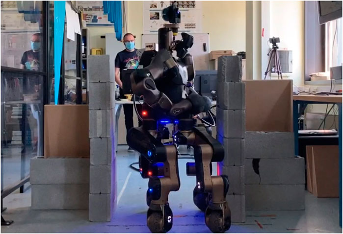
FIGURE 1. CENTAURO passes through a corridor while the null-space posture generator (NSPG) acts by reshaping its whole-body pose.
This paper introduces the literature on previous related approaches and novel contributions to posture generation applied to contacts and whole-body motion planning in Section 2. The methodology is explained in Sections 3 and 4 that will be used later for the algorithm description in Section 5. To conclude, Sections 6 and 7 describe the obtained simulation and experimental results and how the performance of the introduced method compares to that of the previous work.
2 Related Work
The generation of feasible whole-body configurations for a legged robot coupled with footsteps or multi-contact planners has been widely investigated in the past years. The previous work is based on pre-computed paired forward–inverse dynamic reachability maps (DRM/iDRM) to sample in the reachable workspace those configurations that could accomplish a loco-manipulation task while guaranteeing stability and collision safeness on flat Yang et al. (2017) and inclined Ferrolho et al. (2018) terrains. This method is characterized by big computational and memory costs which are reduced, solving for the upper and lower bodies separately. Additionally, it requires the computation and discretization of the reachable workspace which becomes computationally heavier when the number of contacts increases.
In Hauser et al. (2005), an iterative constraint enforcement (ICE) algorithm was used to generate statically stable and collision-free configurations using the Newton–Raphson method. The generated postures are subject to Cartesian constraints for the contacts and CoM position to guarantee stability, starting from randomly sampled initial configurations. However, random seed configurations do not take into account the problem of minimal displacement between adjacent postures, and this could lead to unfeasibilities during the transition motion.
Other approaches explore fixed-size Gutmann et al. (2005); Deits and Tedrake (2014) or variable-size Buchanan et al. (2019) bounding boxes to find the best collision-free walking posture. This whole-body posture is then projected onto the contacts found during the planning phase. However, these methods do not take advantage of the capability of reshaping the whole body of the robot to facilitate and eventually permit transiting in scenarios where the dimensions of the free passage are closely the physical dimensions of the robot body.
In Bouyarmane and Kheddar (2012), a non-linear optimization has been used to compute IK with static stability, collision avoidance, torque limits, and joint limits as constraints. In this work, no further modifications are carried out when the solver is not able to find a solution, leading to a possible avoidable discard of the sampled contact state.
A different approach was used in Tonneau et al. (2018). The contact planner problem is addressed first by finding a guide path for the floating base in the
Recently, in Shigematsu et al. (2019), a posture generator has been developed to plan whole-body trajectories for a humanoid robot moving heavy suitcases. The approach is based on a non-linear program where several key postures are optimized all together with the centroidal statics, joint limits, and self-collision constraints. Despite the impressive results obtained on the real platform, the method does not account for environmental collisions, and it still needs several minutes to compute a sequence of configurations.
3 Methodology
The NSPG aims to generate collision-free whole-body configurations realizing both kinematic and statics constraints that will be detailed in Sections 3.2 and 3.3. These constraints arise from the contacts that the robot is required to establish with the environment to execute an assigned task and are generally the output of a contact planner (Section 3.1). To this end, we introduce in this section the basic notions that will be used in the following.
3.1 Stance Generation
The contact planner defines the pose of the active contacts for the legged robot moving from a start to a goal stance. The basic elements used are as follows:
• A configuration
• A stance
• A configuration
For each state
The configuration space velocities associated with the configurations
In addition, with proper validity functions, we assume to sample stances with poses of the contacts in the workspace of the robots and not inside any obstacle.
3.2 Hierarchical IK
The Cartesian velocity
where
The inverse problem of Eq. 3, a.k.a. differential inverse kinematics, permits to compute the configuration velocities
with
with
The problem in Eq. 4 can be formulated as a quadratic programming (QP) problem with the main advantage of considering equality and inequality constraints as well Kanoun et al. (2011):
Furthermore, hard priorities between tasks can be enforced in the QP-based IK by means of a cascade of QPs Kanoun et al. (2009) or using particular hierarchical orthogonal decomposition of the aggregated task matrices Escande et al. (2014).
We define the following tasks and constraints:
• Contact Task
• with
• with
• Postural Task
• As done in the Cartesian case (5), it is possible to define the desired configuration velocity with a term that tracks a reference robot configuration
• Joint Limits Constraint
• with
We organize these tasks and constraints in the following stack
where the “∑” symbol means that all the contact tasks are summed at the same priority level and the “/” symbol means that the postural task acts in the null-space of the contact tasks and is, hence, the “hierarchical” term in HIK. The “
3.3 Centroidal Statics
To grant quasi-static stability for a given robot configuration
The resulting QP in the variables
The first term in Eq. 14a ensures static stability, under quasi-static conditions, based on the centroidal statics (CS) of the robot, where the terms
with
This reduced description assumes fixed contact placements with associated linearized friction models and unilaterality of the contact force Eq. 14c, center of pressure (CoP) inside the contact surface Eq. 14d, and bounded contact yaw torque Eq. 14eCaron et al. (2015)3, to obtain the interaction forces required to compensate for gravity, achieving static balancing and non-slippage of surface contacts. Matrices
where
It is worth noticing that modeling a surface contact using forces and moments, together with the constraints Eqs. 14c–e, permits to save variables and constraints. Assuming four contact points per surface contact leads to a total of 12 pure contact force variables and 20 constraints in the form of Eq. 16a. On the contrary, assuming a single wrench leads to 6 variables to describe contact forces and torques and 17 constraints. A graphical representation of the centroidal statics’ components is given in Figure 2.
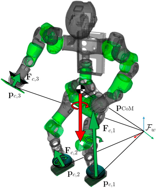
FIGURE 2. Centroidal statics and robot configuration starting from planned contacts. The green arrows represent the contact forces and torques. These lasts are limited to the surface contacts only (feet). The friction cones are also shown for the three active contacts. The red arrows represent the weight force and the derivative of the angular momentum exerted directly on the CoM of the robot. Position vectors of each contact and CoM are highlighted w.r.t. the inertial frame
The residual of the first term in the cost function Eq. 14a is used to decide whether a configuration is stable or not when satisfying a specific stance, depending on a threshold value.
4 Generating Transition Configurations
In a contact planner application case, a feasible sequence of adjacent postures is required to be connectable in order to build a configuration path that moves the robot safely from a start configuration
with
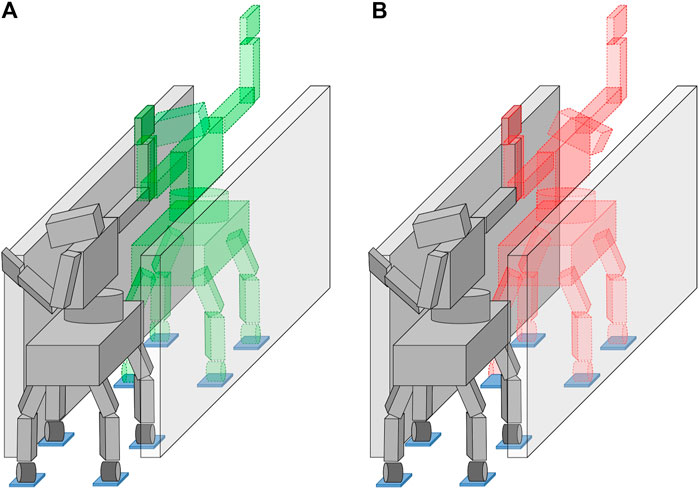
FIGURE 3. An example of how generating adjacent poses with large differences can lead to an unfeasible colliding transition during their connection. Starting from the same robot configuration in gray, the next posture is generated minimizing the differences w.r.t. the parent state, on the left, or facing the opposite side of the corridor with the upper body, on the right. Even though all the generated poses are feasible, the right scenario will lead to a collision with the environment while connecting the two consecutive states.
Furthermore, in the assumption that near stances differ by exactly one active contact, the generated configuration
5 Null-Space Posture Generator
Our approach is based on a complete reshape of the robot configuration, obtained by adjusting the pose of kinematic chains in a collision, or moving the root link to recover the static stability, in the null-space of the Cartesian (contact) tasks. Specifically, each detected unfeasibility will generate random velocity components aiming to recover feasibility. This section follows a pipeline going through each component of the algorithm: first, the nominal configuration and the random velocity vector
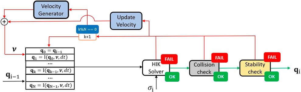
FIGURE 4. NSPG flow diagram: the configuration
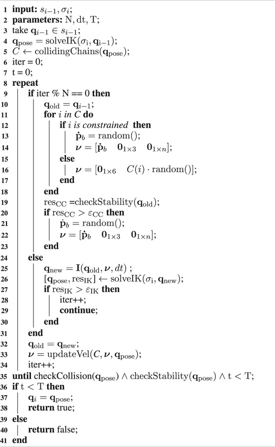
ALGORITHM 1:. NSPG( ).
5.1 Nominal Configuration Generation
First, the candidate configuration
5.2 Adaptive Random Velocity Vector Generation
In the following, the procedure to generate the random velocity vector
5.2.1 Collisions
In this phase, we take advantage of the kinematic structure of a multi-limbed robot to avoid collisions while keeping low differences between adjacent configurations. Indeed, the motion of a kinematic chain is independent concerning the others, assuming that its end-effector is not constrained onto a contact pose. In this way, we can freely move only the chain(s) involved in unfeasibility, preventing avoidable motions that could lead to other collisions.
In detail, when
It is worth mentioning that collisions/self-collisions can be avoided as well as integrating specific cost functions or constraints in the HIK Fang et al. (2015); Stasse et al. (2008). Despite appealing, this inclusion may have a non-negligible computational cost which is avoidable when HIK is used as a posture generator. The increase in computational cost grows together with the complexity of the surrounding environment which makes the active set computationally expensive. For kinematic chains fully constrained onto the set of contacts defined by
With this methodology, the NSPG moves only the joints involved in unfeasibility preventing avoidable motions of the rest of the body.
5.2.2 Stability
A second scenario occurs when
In this case, linear velocities of the root link are generated from a uniform random distribution bounded between two arbitrarily big numbers (
It has been chosen to move the root link instead of the CoM directly since a motion of the latter could imply an undesired whole-body motion involving non-colliding kinematic chains or deviating the motion of the colliding ones unpredictably.
5.3 Candidate Configuration Update
The postural task reference is then updated according to the new velocity vector (line 25), and the HIK is solved generating a new robot configuration
5.4 Velocity Vector Adaptation
While running, the algorithm will generate configurations with arbitrarily small differences which depends on its parameters and velocity vector
Collision and stability checks strictly depend on the current candidate configuration of the robot that changes at each iteration of the algorithm. Thus, the velocity vector
Specifically, at each iteration, the colliding chains are updated, and two new sub-sets are defined:
with
with
At each iteration, this method looks for a feasible configuration inside a maximum allowable workspace around the nominal configuration. The maximum volume of the robot workspace is defined by the parameters
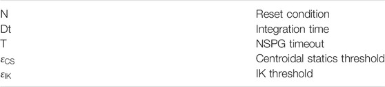
TABLE 1. NSPG parameters.
6 Results
The proposed NSPG algorithm has been tested in two scenarios with increasing difficulty, applied on two different types of legged hyper-redundant robots: the hybrid wheeled-legged quadrupedal robot CENTAURO and the biped robot COMAN+. CENTAURO is a robot with 39 DoFs split between a quadrupedal lower body and a bimanual humanoid upper body, while COMAN+ is a biped humanoid robot with 28 DoFs.
The first considered scenario consists of multiple tiles, placed at different heights and orientations, where the robot has to step on or place its limbs, while the second one is a narrow corridor on a flat terrain. Additionally, an experiment of this last scenario has been carried out on CENTAURO.
Our NSPG implementation is based on the OpenSoT Hoffman et al. (2017) and CartesI/O Laurenzi et al. (2019) frameworks for the computation of the whole-body HIK and centroidal statics QP problems, depicted in Sections 3.2 and 3.3, respectively. In particular, QPs are efficiently solved using well-known QP solvers such as qpOASESFerreau et al. (2014) or OSQPStellato et al. (2020). Collisions are detected exploiting the Flexible Collision Library (FCL) Pan et al. (2012) using convex-hull approximations of the links of the robot.
All videos showing the presented simulations and real experiments are included in the material accompanying this paper6.
6.1 Non-Co-Planar Contact Scenario
The NSPG has been tested in the scenario where an external planner returns a series of feasible stances only. In this case, the contact state can be written as
Specifically, the humanoid robot has to climb a stair of three steps on a sequence of 18 stances. The first two steps are flat, while the last two are rotated 0.25 rad along the x-axis (see Figure 5). The stances are such that they respect the principle of connectivity described in Section 4, and the NSPG has to find a series of feasible configurations
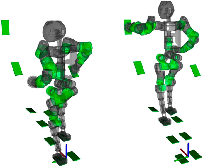
FIGURE 5. Captures of COMAN+ moving on a sequence of predefined stances while the NSPG generates feasible configurations.
In this scenario, we want to stress the capability of the NSPG to find collision-free and stable configurations while stepping on non-co-planar stances, using a whole-body approach.
We analyze the NSPG performance on 10 runs using the same sequence of stances. The results are collected in Figure 6: the NSPG is always able to find all the 18 feasible configurations, changing the active links accordingly, in approximately 2.2 s with an average of 0.12 s for each generated configuration.
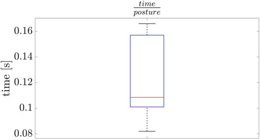
FIGURE 6. Results from the scenario in Section 6.1.
6.2 Corridor Scenario
The NSPG has been also tested in a particularly tricky scenario for a sample-based planner algorithm: a narrow corridor (Kingston et al. (2018)). In particular, CENTAURO and COMAN+ are asked to traverse a narrow corridor
When planning with COMAN+ instead, locomotion is achieved by continuously switching between the two feet, i.e., the walking pattern. In particular, a sequence of single and double stances is computed by the planner and connectivity is guaranteed generating single-stance statically stable configurations. Indeed, the next double-stance configuration can be reached if and only if it is single-stance stable, avoiding the robot to go through an unstable region while walking (see Section 4). This is particularly challenging from both stability and collision safeness points of view since the robot has to move its CoM between the two stance feet while moving in the corridor.
In this scenario, the NSPG is used inside a planner routine, implemented using OMPL Şucan et al. (2012), to validate the sampled stances. Every time a new stance
Three parameter setups were tried in this scenario to test how the performance of the NSPG changes. This was evaluated collecting data about the average time employed to find a feasible posture:
with
with
An additional statistic has been added considering the causes of failure. Indeed, the NSPG can fail due to collision check and static stability check failure. The necessity to always check both the stability and collision safeness is required by the NSPG to update the velocity vector

TABLE 2. Percentages of fail of the centroidal statics check (
Differently, when generating configurations with COMAN+, the stability check fails twice the collision check since we are looking for a single-stance stable configuration while moving through a narrow environment. Notice that the sum of the two percentages goes over 100% since the NSPG can fail due to a contemporary fail of the stability and collision checks.
The results are collected in Table 3, which confirm the observations just done. Screenshots of the simulations with both COMAN+ and CENTAURO are shown in Figure 7 and Figure 8. Real experiments with CENTAURO in this scenario are shown in Figure 9. A complete description of the controller used is given in Appendix 1. In both the simulated and real experiments, the surrounding environment is detected using perception data based on a 3D point cloud generated by a Lidar sensor. The data are collected following the work in Hornung et al. (2013).

TABLE 3. Results from the scenario in Section 6.2:
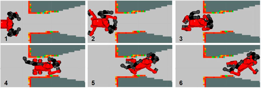
FIGURE 7. Screenshots of CENTAURO passing through the high narrow corridor.
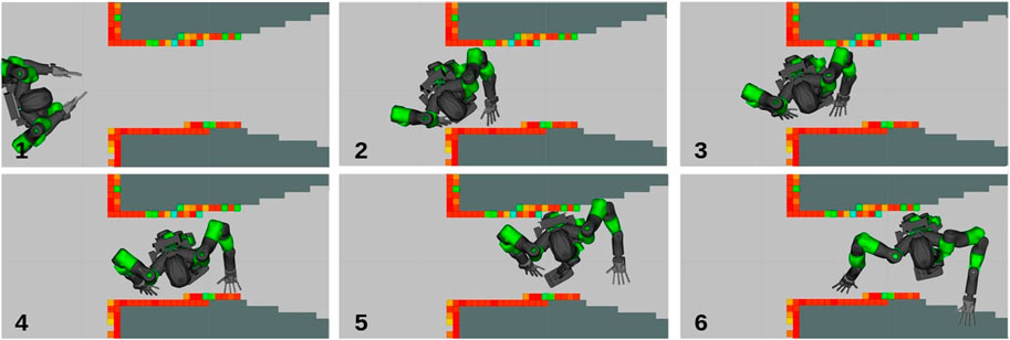
FIGURE 8. Screenshots of COMAN+ passing through the high narrow corridor.
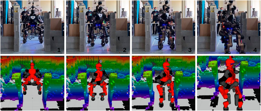
FIGURE 9. Screenshots from the experiment carried out on a CENTAURO robot. From top left to bottom right, the robot first approaches the narrow corridor keeping the homing position as far as no collisions are detected. As soon as the robot starts entering the corridor, the NSPG reshapes the support polygon and the upper body at the same time.
6.3 Discussion
The NSPG has been designed to generate whole-body configurations for multi-limbed robots in a particularly complex environment. For instance, (multi-)contact planners generally require a precise representation of an extensive environment, usually obtained through point clouds. As already mentioned, in these scenarios, the use of HIK solvers, coupled with specific constraints for obstacle avoidance, can be computationally heavy since they are based on the computation of the distances between each link of the robot and each obstacle in the environment (i.e., each point of the point cloud). Based on these distances, several methods have been proposed to move the robot away from the singularity. On the contrary, the NSPG does not need any particular strategy to avoid collisions, and the only requirement is the computation of the distances mentioned above. The results in Table 3 show how this computation can be efficiently done even in a complex environment acquired through a Lidar sensor.
To motivate this, an additional simulation with COMAN+ has been run in an environment similar to the one described in Section 6.2. This time, the NSPG does not take into account collisions to generate the random velocity vector

TABLE 4. Comparison between the results obtained when generating configurations with the NSPG with and without the collision avoidance constraint. In the first case, the random velocity vector is generated and updated depending only on the static stability of the robot. The table contains the same parameters as in Table 3.
As expected, when using the linear constraint for collision avoidance in a complex environment detected through a dense point cloud, the time to solve the HIK dramatically increases by three orders of magnitude. The average time for the collision check is dropped to zero, but this improvement is not enough to justify such an increase in computational cost for the HIK and this is reflected in the overall performances of the NSPG. The percentage of success drops to 43.7% since the average time to find a feasible configuration goes over 2 s with a timeout of 1 s. In addition, the average number of iterations for each call of the NSPG decreases to 15 reducing its capability to explore the workspace.
7 Conclusion
This work presents a novel algorithm, named the null-space posture generator (NSPG), able to efficiently generate stable and (self-)collision-free whole-body postures for a generic, multi-limbed, floating-base robot, given a sequence of stances. The NSPG has been developed to speed up the whole-body motion planning of complex robotic systems when passing through particularly challenging environments keeping the tuning procedure as light as possible. Indeed, benefits from computation and efficiency points of view have been demonstrated when applying this algorithm in a particularly complex environment compared to previous methods that use the constraint in the HIK to generate statically stable and collision-free configurations. Furthermore, it can also be used independently as a posture generator, given the active contacts as shown in Section 6.1.
Multiple experiments on two profoundly different robotic platforms, COMAN+ and CENTAURO, demonstrated that the NSPG is capable of quickly generating stable and collision-free configurations for a legged robot in contact with the environment, exploiting null-space motions. In particular, CENTAURO represents a challenging platform for planning considering the high number of DoFs. Real experiments were also carried out on CENTAURO using a Lidar sensor to perceive the environment, demonstrating the applicability of the proposed approach to a real scenario.
Our implementation of the NSPG can generate approximately 1,000 configurations per second, guaranteeing a good exploration despite using a light random approach able to adapt while exploiting the robot’s workspace depending on the unfeasibility occurrence.
The proposed method, even if based on a random approach, presents a good level of reliability which is observed in the result obtained in the two considered scenarios. Additionally, it does not require a big effort to tune its parameters, which does not depend on the robotic platform in use, as it has been seen by the general applicability of the algorithm to two profoundly different robotic platforms.
Comparing our results to the recent work proposed in Shigematsu et al. (2019), in the cluttered scenario (Section 6.1), we were able to double the configurations with an average time smaller than three orders of magnitude, guaranteeing minimal differences between adjacent postures.
Future work will involve the use of the NSPG in a multi-contact planner scenario similar to the one used to generate stances in Section 6.1. Furthermore, the stability check could be improved considering centroidal dynamics, allowing higher dynamic motions and enlarging the set of possible feasible configurations and applications, i.e., kinodynamic planning. Additionally, post-processing of the joint trajectory generated should be investigated in order to correct any unfeasibility during the interpolation or to minimize a user-defined cost function (i.e., minimum length path), using the planner output as an initial guess.
Data Availability Statement
The original contributions presented in the study are included in the article/Supplementary Material, and further inquiries can be directed to the corresponding author.
Ethics Statement
Written informed consent was obtained from the individual(s) for the publication of any potentially identifiable images or data included in this article.
Author Contributions
LR wrote the manuscript and conducted the simulations and experiments. LR, EH, and AL contributed together to writing the algorithm. All authors reviewed the manuscript.
Funding
This work was supported by the European Union’s Horizon 2020 Research and Innovation Programme under Grant No. 779963 (EUROBENCH).
Conflict of Interest
The authors declare that the research was conducted in the absence of any commercial or financial relationships that could be construed as a potential conflict of interest.
Publisher’s Note
All claims expressed in this article are solely those of the authors and do not necessarily represent those of their affiliated organizations, or those of the publisher, the editors and the reviewers. Any product that may be evaluated in this article, or claim that may be made by its manufacturer, is not guaranteed or endorsed by the publisher.
Acknowledgments
For the constant and useful support during this experimental campaign, despite the obvious difficulties of the last period, the authors would like to personally thank Matteo Parigi Polverini, Francesco Ruscelli, Vignesh Sushrutha Raghavan, Paolo Ferrari, and Diego Vedelago.
Supplementary Material
The Supplementary Material for this article can be found online at: https://www.frontiersin.org/articles/10.3389/frobt.2021.715325/full#supplementary-material
Footnotes
1Here and in what follows, for the sake of brevity of the notation, we do not express the dependence of the matrices on the configuration
2For a point contact,
3Constraints (14d) and (14e) are considered only for surface contacts.
4Here, the contact frame is assumed at the center of the surface for simplicity and modeled as rectangular.
5
References
Bouyarmane, K., and Kheddar, A. (2012). Humanoid Robot Locomotion and Manipulation Step Planning. Adv. Robotics 26, 1099–1126. doi:10.1080/01691864.2012.686345
Buchanan, R., Bandyopadhyay, T., Bjelonic, M., Wellhausen, L., Hutter, M., and Kottege, N. (2019). Walking Posture Adaptation for Legged Robot Navigation in Confined Spaces. IEEE Robot. Autom. Lett. 4, 2148–2155. doi:10.1109/lra.2019.2899664
Caron, S., Pham, Q.-C., and Nakamura, Y. (2015). “Stability of Surface Contacts for Humanoid Robots: Closed-form Formulae of the Contact Wrench Cone for Rectangular Support Areas,” in IEEE International Conference on Robotics and Automation (ICRA), 26-30 May 2015, Seattle, WA, USA, 5107–5112. doi:10.1109/ICRA.2015.7139910
Cognetti, M., Mohammadi, P., and Oriolo, G. (2015). “Whole-body Motion Planning for Humanoids Based on Com Movement Primitives,” in IEEE-RAS International Conference on Humanoid Robots (HUMANOIDS), 3-5 November 2015, Seoul, Korea (South), 1090–1095. doi:10.1109/humanoids.2015.7363504
Deits, R., and Tedrake, R. (2014). “Footstep Planning on Uneven Terrain with Mixed-Integer Convex Optimization,” in 2014 IEEE-RAS International Conference on Humanoid Robots (HUMANOIDS), 18-20 Nov. 2014, Madrid, Spain, 279–286. doi:10.1109/HUMANOIDS.2014.7041373
Escande, A., Kheddar, A., and Miossec, S. (2013). Planning Contact Points for Humanoid Robots. Robotics Autonomous Syst. 61, 428–442. doi:10.1016/j.robot.2013.01.008
Escande, A., Mansard, N., and Wieber, P.-B. (2014). Hierarchical Quadratic Programming: Fast Online Humanoid-Robot Motion Generation. Int. J. Robotics Res. 33, 1006–1028. doi:10.1177/0278364914521306
Fang, C., Rocchi, A., Hoffman, E. M., Tsagarakis, N. G., and Caldwell, D. G. (2015). “Efficient Self- Collision Avoidance Based on Focus of Interest for Humanoid Robots,” in 2015 IEEE-RAS 15th International Conference on Humanoid Robots (HUMANOIDS), 3-5 November 2015, Seoul, Korea (South), 1060–1066. doi:10.1109/HUMANOIDS.2015.7363500
Ferrari, P., Cognetti, M., and Oriolo, G. (2018). “Anytime Whole-Body Planning/replanning for Humanoid Robots,” in IEEE-RAS International Conference on Humanoid Robots (Humanoids), 6-9 November 2018, Beijing, China, 1–9. doi:10.1109/humanoids.2018.8624935
Ferreau, H. J., Kirches, C., Potschka, A., Bock, H. G., and Diehl, M. (2014). qpOASES: a Parametric Active-Set Algorithm for Quadratic Programming. Math. Prog. Comp. 6, 327–363. doi:10.1007/s12532-014-0071-1
Ferrolho, H., Merkt, W., Yang, Y., Ivan, V., and Vijayakumar, S. (2018). “Whole-body End-Pose Planning for Legged Robots on Inclined Support Surfaces in Complex Environments,” in 2018 IEEE-RAS 18th International Conference on Humanoid Robots (HUMANOIDS), 6-9 Nov. 2018, Beijing, China, 944–951. doi:10.1109/HUMANOIDS.2018.8625026
Gutmann, J.-S., Fukuchi, M., and Fujita, M. (2005). “Real-time Path Planning for Humanoid Robot Navigation,” in International Joint Conferences on Artificial Intelligence (IJCAI), 30 July 2005- 5 August 2005, Edinburgh Scotland, 1232–1237.
Hauser, K., Bretl, T., Latombe, J.-C., Harada, K., and Wilcox, B. (2008). Motion Planning for Legged Robots on Varied Terrain. Int. J. Robotics Res. 27, 1325–1349. doi:10.1177/0278364908098447
Hauser, K., Bretl, T., and Latombe, J. (2005). “Non-gaited Humanoid Locomotion Planning,” in IEEE-RAS International Conference on Humanoid Robots (HUMANOIDS), 5-5 Dec. 2005, 5-5 Dec. 2005, Tsukuba, Japan, 7–12.
Hoffman, E. M., Rocchi, A., Laurenzi, A., and Tsagarakis, N. G. (2017). “Robot Control for Dummies: Insights and Examples Using Opensot,” in 2017 IEEE-RAS 17th International Conference on Humanoid Robotics (HUMANOIDS), 15-17 Nov. 2017, Birmingham, UK, 736–741. doi:10.1109/HUMANOIDS.2017.8246954
Hornung, A., Wurm, K. M., Bennewitz, M., Stachniss, C., and Burgard, W. (2013). OctoMap: An Efficient Probabilistic 3D Mapping Framework Based on Octrees. Autonomous Robots 34, 189–206. doi:10.1007/s10514-012-9321-0
Kanoun, O., Lamiraux, F., Wieber, P.-B., Kanehiro, F., Yoshida, E., and Laumond, J.-P. (2009). “Prioritizing Linear equality and Inequality Systems: Application to Local Motion Planning for Redundant Robots,” in IEEE international conference on robotics and automation (ICRA), 12-17 May 2009, Kobe, Japan, 2939–2944. doi:10.1109/robot.2009.5152293I
Kanoun, O., Lamiraux, F., and Wieber, P.-B. (2011). Kinematic Control of Redundant Manipulators: Generalizing the Task-Priority Framework to Inequality Task. IEEE Trans. Robot. 27, 785–792. doi:10.1109/tro.2011.2142450
Kashiri, N., Cordasco, S., Guria, P., Margan, A., Tsagarakis, N. G., Baccelliere, L., et al. (2019). Centauro: A Hybrid Locomotion and High Power Resilient Manipulation Platform. IEEE Robot. Autom. Lett. 4, 1595–1602. doi:10.1109/lra.2019.2896758
Kingston, Z., Moll, M., and Kavraki, L. E. (2018). Sampling-based Methods for Motion Planning with Constraints. Annu. Rev. Control. Robot. Auton. Syst. 1, 159–185. doi:10.1146/annurev-control-060117-105226
Kuffner, J. J., Nishiwaki, K., Kagami, S., Inaba, M., and Inoue, H. (2001). “Footstep Planning Among Obstacles for Biped Robots,” in IEEE-RSJ International Conference on Intelligent Robots and Systems (IROS), 29 Oct.-3 Nov. 2001, Maui, HI, 1, 500–505.
Kuindersma, S., Deits, R., Fallon, M., Valenzuela, A., Dai, H., Permenter, F., et al. (2016). Optimization-based Locomotion Planning, Estimation, and Control Design for the Atlas Humanoid Robot. Auton. Robot 40, 429–455. doi:10.1007/s10514-015-9479-3
Laurenzi, A., Hoffman, E. M., Muratore, L., and Tsagarakis, N. G. (2019). “CartesI/O: A Ros Based Real-Time Capable Cartesian Control Framework,” in 2019 International Conference on Robotics and Automation (ICRA), 20-24 May 2019, Montreal, QC, 591–596. doi:10.1109/ICRA.2019.8794464
Mingo Hoffman, E., and Tsagarakis, N. G. (2021). The Math of Tasks: a Domain Specific Language for Constraint-Based Task Specification. Int. J. Humanoid Robotics, 2150008. under review. doi:10.1142/s0219843621500080
Pan, J., Chitta, S., and Manocha, D. (2012). “Fcl: A General Purpose Library for Collision and Proximity Queries,” in IEEE International Conference on Robotics and Automation (ICRA), 3859–3866. doi:10.1109/icra.2012.6225337
Polverini, M. P., Laurenzi, A., Hoffman, E. M., Ruscelli, F., and Tsagarakis, N. G. (2020). Multi-Contact Heavy Object Pushing with a Centaur-type Humanoid Robot: Planning and Control for a Real Demonstrator. IEEE Robot. Autom. Lett. 5, 859–866. doi:10.1109/lra.2020.2965906
Ratliff, N., Zucker, M., Bagnell, J. A., and Srinivasa, S. (2009). Chomp: Gradient Optimization Techniques for Efficient Motion Planning. IEEE International Conference on Robotics and Automation (ICRA), 12-17 May 2009, Kobe, Japan, 489–494. doi:10.1109/ROBOT.2009.5152817
Ruscelli, F., Polverini, M. P., Laurenzi, A., Hoffman, E. M., and Tsagarakis, N. G. (2020). “A Multi-Contact Motion Planning and Control Strategy for Physical Interaction Tasks Using a Humanoid Robot,” in IEEE - RSJ International Conference on Intelligent Robots and Systems (IROS), 24 Oct.-24 Jan. 2021, 24 Oct.-24 Jan. 2021, 3869–3876. doi:10.1109/IROS45743.2020.9340745
Shigematsu, R., Murooka, M., Kakiuchi, Y., Okada, K., and Inaba, M. (2019). “Generating a Key Pose Sequence Based on Kinematics and Statics Optimization for Manipulating a Heavy Object by a Humanoid Robot,” in 2019 IEEE/RSJ International Conference on Intelligent Robots and Systems (IROS), 3-8 November 2019, Macau, China, 3852–3859. doi:10.1109/IROS40897.2019.8967902
Stasse, O., Escande, A., Mansard, N., Miossec, S., Evrard, P., and Kheddar, A. (2008). “Real-time (Self)-collision Avoidance Task on a Hrp-2 Humanoid Robot,” in IEEE International Conference on Robotics and Automation (ICRA). 19-23 May 2008, Pasadena, CA, 3200–3205. doi:10.1109/ROBOT.2008.4543698
Stellato, B., Banjac, G., Goulart, P., Bemporad, A., and Boyd, S. (2020). OSQP: an Operator Splitting Solver for Quadratic Programs. Math. Prog. Comp. 12, 637–672. doi:10.1007/s12532-020-00179-2
Sucan, I. A., Moll, M., and Kavraki, L. E. (2012). The Open Motion Planning Library. IEEE Robot. Automat. Mag. 19, 72–82. doi:10.1109/mra.2012.2205651
Tonneau, S., Del Prete, A., Pettré, J., Park, C., Manocha, D., and Mansard, N. (2018). An Efficient Acyclic Contact Planner for Multiped Robots. IEEE Trans. Robot. 34, 586–601. doi:10.1109/TRO.2018.2819658
Yang, Y., Ivan, V., Merkt, W., and Vijayakumar, S. (2016). “Scaling Sampling-Based Motion Planning to Humanoid Robots,” in IEEE International Conference on Robotics and Biomimetics (ROBIO). 3-7 December 2016, Qingdao, China, 1448–1454. doi:10.1109/ROBIO.2016.7866531
Yang, Y., Merkt, W., Ferrolho, H., Ivan, V., and Vijayakumar, S. (2017). Efficient Humanoid Motion Planning on Uneven Terrain Using Paired Forward-Inverse Dynamic Reachability Maps. IEEE Robot. Autom. Lett. 2, 2279–2286. doi:10.1109/LRA.2017.2727538
A Centauro Controller
In this section, the controller strategy used to replicate the methodology on the real robot CENTAURO will be detailed. Once the discrete collision-free poses have been found, they are connected by using a third-order polynomial interpolation, except for the steering and rolling joints of the wheels, which need special care as detailed hereafter.
Taking advantage of the possibility of rolling toward the next state instead of taking a step, wheels must be first re-oriented in the right direction. For this purpose, a proper controller has been designed as shown in Figure 10: at each state transition, given the initial and final wheel positions from states
where
where α is the rotation that moves the
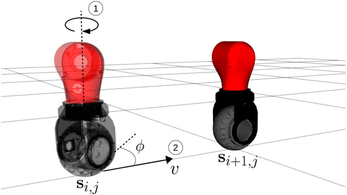
FIGURE 10. A graphical representation of the wheel control logic. First, the
A naive polynomial interpolation cannot guarantee a safe transition of the robot through the discrete configurations. However, in the assumption of small differences between adjacent postures, the probability to encounter unfeasibility drastically decreases. Additionally, an impedance controller guarantees minimum impact consequences in the unluckily event that a small collision occurs while interpolating. Finally, the interpolated trajectory is sent to the robot, and it is tracked through a joint-level impedance controller.
Keywords: whole-body planning, posture generation, humanoid robot, legged robot, hierarchical inverse kinematics, optimization
Citation: Rossini L, Hoffman EM, Laurenzi A and Tsagarakis NG (2021) NSPG: An Efficient Posture Generator Based on Null-Space Alteration and Kinetostatics Constraints. Front. Robot. AI 8:715325. doi: 10.3389/frobt.2021.715325
Received: 26 May 2021; Accepted: 12 July 2021;
Published: 10 August 2021.
Edited by:
Fumio Kanehiro, National Institute of Advanced Industrial Science and Technology (AIST), JapanReviewed by:
Masaki Murooka, National Institute of Advanced Industrial Science and Technology (AIST), JapanHenrique Ferrolho, University of Edinburgh, United Kingdom
Christopher Yee Wong, Université de Sherbrooke, Canada
Copyright © 2021 Rossini, Hoffman, Laurenzi and Tsagarakis. This is an open-access article distributed under the terms of the Creative Commons Attribution License (CC BY). The use, distribution or reproduction in other forums is permitted, provided the original author(s) and the copyright owner(s) are credited and that the original publication in this journal is cited, in accordance with accepted academic practice. No use, distribution or reproduction is permitted which does not comply with these terms.
*Correspondence: Luca Rossini, bHVjYS5yb3NzaW5pQGlpdC5pdA==