 Moran Gad
 Ben Lev-Ari1
 Coral Ben-David
 Raziel Riemer
- 1Mechanical Engineering Department, Ben-Gurion University of the Negev, Beer-Sheva, Israel
- 2Industrial Engineering and Management Department of Ben-Gurion University of the Negev, Beer-Sheva, Israel
Biomechanical energy harvesters are designed to generate electrical energy from human locomotion (e.g., walking) with minimal or no additional effort by the users. These harvesters aim to carry out the work of the muscles during phases in locomotion where the muscles are acting as brakes. Currently, many harvesters focus on the knee joint during late swing, which is only one of three phases available during the gait cycle. For the device to be successful, there is a need to consider design components such as the motor/generator and the gear ratio. These components influence the amount of electrical energy that could be harvested, metabolic power during harvesting, and more. These various components make it challenging to achieve the optimal design. This paper presents a design of a knee harvester with a direct drive that enables harvesting both in flexion and extension using optimization. Subsequently, two knee devices were built and tested using five different harvesting levels. Results show that the 30% level was the best, harvesting approximately 5 W of electricity and redacting 8 W of metabolic energy compared to walking with the device as a dead weight. Evaluation of the models used in the optimization showed a good match to the system model but less for the metabolic power model. These results could pave the way for an energy harvester that could utilize more of the negative joint power during the gait cycle while reducing metabolic effort.
1 Introduction
Biomechanical energy harvesters are exoskeletons designed to generate electrical energy from human locomotion (e.g., walking) and provide an alternative to batteries as an electrical power source for portable electronics (GPS, laptops, etc.). Many current harvesting devices aim to carry out part of the work of the muscles during phases in human locomotion where the muscles are acting as brakes (i.e., negative muscle work) (Donelan et al., 2008), (Niu et al., 2004), see Figure 2. This leads to regenerative braking, which generates electrical energy in a similar way to a hybrid car and may reduce the user’s effort. For energy-harvesting devices to be useful, it is important that the addition of effort (metabolic rate) required to carry the device on the body and to generate electrical energy is minimal or negative (Schertzer and Riemer, 2015).
While the exact conditions required for achieving harvesting while reducing metabolic energy are unknown, there where evidence in the past that this is possible (Donelan et al., 2008), (Shepertycky and Li, 2015). Further, a recently developed energy harvester utilized late swing to produce 0.25 W of electrical energy while reducing the metabolic energy (relative to walking with no device) by 6 W (Shepertycky et al., 2021). There could be several types of biomechanical energy; the main ones are a backpack that uses the oscillation of the center of mass, a shoe base that uses sole compression to generate electrical energy, and a joint base that uses the relative motion between the segments (Riemer and Shapiro, 2011). Currently, the most successful harvesters are devices that target negative muscle work performed at the knee, as this is a joint with a relatively large amount of negative work performed at that location (Figure 2). However, current knee devices [(Donelan et al., 2008), (Shepertycky and Li, 2015), (Shepertycky et al., 2021)] are focused on the late swing (end on K4), which means that they can only make use of less than half of the potential energy that could be harvested during a full gait cycle (Riemer and Shapiro, 2011). Moreover, the ability of these devices in harvesting is limited, due to their mechanical design, which uses a roller clutch (Donelan et al., 2008) or a combination of a roller clutch and cable (Shepertycky and Li, 2015; Shepertycky et al., 2021). In this context, they can harvest only at the flexion of the knee.
During device design, several parameters must be considered. First, the device must be attached to the body, and carrying its mass requires additional metabolic power from the user. The metabolic rate required to carry the device is based on the user’s walking speed and the device’s mass and location (Browning et al., 2007)– (Schertzer and Riemer, 2014) (Stuempfle et al., 2004; Soule and Goldman, 1969). Other important design components and their specifications include the motor/generator and the gear ratio. (Note that since the electrical motor is also used as the generator in this study, we use these terms interchangeably). All the aforementioned components have an effect on the other components as well as on the overall performance. Further, some of the design parameters improve the device in one domain, but make it worse in another. For example, the combination of gear, motor, and current determine the resistance torque of the device; a higher gear ratio may produce more electricity, but it might lower the conversion efficiency of the system due to increased friction (higher gear ratios are less efficient). Further, a higher gear ratio will increase the inertia and require more effort from users, especially in non-harvesting phases of the gait. Harvesting more electrical energy will increase the applied torque and forces working on the system, which affects the stress on the structure, its dimensions and mass. All of the above make the task of finding the optimal design challenging.
To address this issue, Li et al. (2009) used a static model (i.e., one that did not include system dynamics) to optimize device efficiency as a function of the gear ratio and the external electrical load of the motor. However, they found that dynamic effects can account for as much as half of the resistance torque applied by the device, which means that the device parameters chosen by their optimization might not have been optimal. Martin et al. (2016) proposed a model that included dynamic effects for a lower limb-driven energy harvester. However, they did not suggest a framework for optimizing the design parameters of the harvester.
The aim of this study is to design and build a knee energy-harvesting device that could generate electricity during joint mechanical negative work phases of the gait, both at flexion and extension. To achieve the best design, we used an optimization process that considers the design parameters of our device, such as the generator’s electrical specification, mass, and gear ratio. The optimization framework was based on a dynamic model of the electromechanical system. Further, we were able to control the torque applied to the knee by the device using technology from our previous study (Cervera et al., 2016). The optimization objective is to minimize the total cost of harvesting (TCOH), which consists of the change in metabolic power when walking with the device vs. without it divided by the electrical power produced (Shepertycky and Li, 2015).
2 Methods
2.1 Overview
The design of the device entailed the following steps
1) Conceptual design of the system,
2) Optimization to minimize the total cost of harvesting, and
3) Calculation of the TCOH using three models. The models were a)
a) Model for the electrical power generated during the system’s operation
b) A dynamic model of the electromechanical system, including prediction of the device’s applied torque profile; and
c) A prediction model for the change in the metabolic power as a function of the device’s mass, location on the body, and torque.
2.2 Conceptual design of device
The device is based on a gear train that increases the angular velocity of the knee to rotate a brushless DC motor (functioning as an electrical generator). The apparatus of the harvesting device is mounted on an orthopedic knee brace (Figure 1). Using a micro-controller, the device controls the torque applied to the knee, which in turn controls the amount of energy to be harvested (Cervera et al., 2016). To reduce the metabolic cost of carrying the device, the gear and generator are located as high as possible on the thigh. Energy harvesting occurs during negative joint work periods, specifically during phases K1, K3, and K4 of the gait cycle (Figure 2). To enable harvesting during both knee flexion and extension, the motor is connected with no clutch mechanism (direct drive). We also tested an option for two oppositely oriented roller clutches that could enable harvesting in both directions, but similar to (Donelan et al., 2008), we found that this design was too heavy.
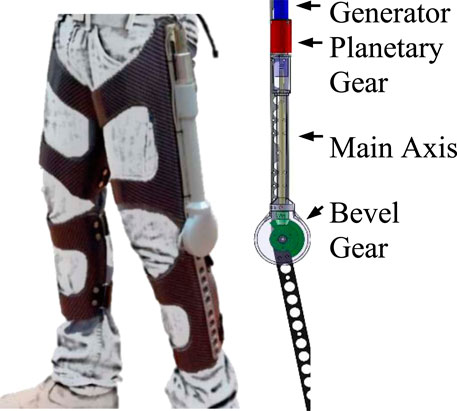
FIGURE 1. General mechanical design of the harvesting device mounted on the knee brace.
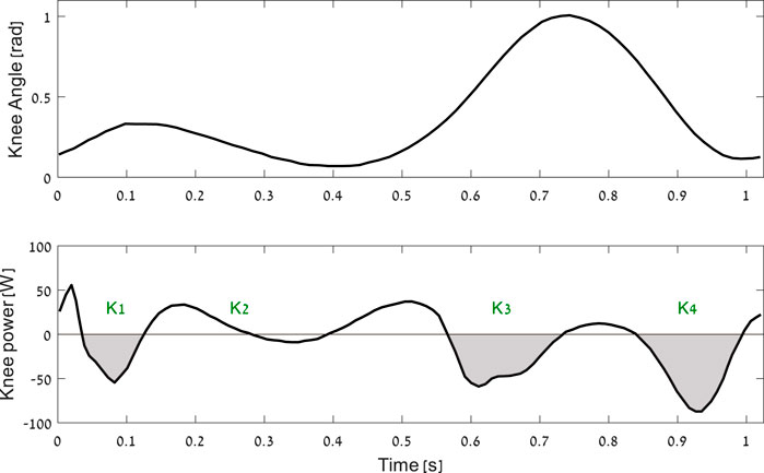
FIGURE 2. The mechanics of the knee joint during a walking gait cycle from heel strike to heel strike. The shaded areas (i.e., K1, K3, and K4) are the phases of negative net muscle work at joint level [based on (Winter, 2009)].
2.3 Objective function
The objective function is to minimize the total cost of harvesting (TCOH, where the optimization parameters are the generator model (from a list of possible generators), the gear ratio, and the torque/current profile. The general optimization formula is
where
where
2.4 Models
This section describes the mathematical derivation of the three models: 1) system power model, 2) system torque model, and 3) change in metabolic rate due to carrying the device and change in the net joint work [based on (Margaria, 1968)].
2.4.1 System’s electrical power model
The power model estimates the effective electrical power that the harvester will be able to produce. We define the system’s effective power as
where
where
where
where
2.4.2 System’s torque model
This model calculates the torque applied by the harvesting device to the knee during the negative joint mechanical power phase of walking, which is formulated as
where
where
where
where
where
where
2.4.3 Estimation of user’s additional metabolic power
The model for
where
To model the effect of carrying the mass on the body, we used equations from (Schertzer and Riemer, 2015), which resulted in
where
where
Finally, to calculate
where
2.4.4 Optimization formulation and constraints
The goal of the optimization is to minimize the TCOH. Thus, the optimization problem, given in (2) and repeated here for convenience, is as follows:
subject to
Where
The inequality constraints in (20) represent the physical limitations of the harvester system components. The upper bound of the gear ratio was selected based on the data sheet of the Apex planetary gearbox—AM032 series with three stages (Apex Dynamics, Long Island, NY, United States). These planetary gearboxes are suitable for our harvester since they enable the application of a maximum torque of 15 Nm at the knee, which is more than half of the maximum of the knee joint torque at the K3 and K4 phases. In addition, they have weights and sizes that are suitable for a wearable device. Note that we did not harvest at K1, as it requires a higher gear ratio than K3 and K4.
The optimization controls the harvester torque profile. This torque profile was designed based on our own electric controller (Cervera et al., 2016), (Rubinshtein et al., 2014) and on our experimental results for walking.
It should be noted that if the storage capacitor is not full, it might still be possible to harvest, but this condition cannot be guaranteed. Therefore, in the optimization algorithm, we chose not to harvest energy when
We applied our optimization for level walking where the input for motion is the knee joint average angular data. The timing of the harvesting algorithm was based on mapping the average knee joint angle profile to the average negative power profile. In a previous experiment, we found significant variation between subjects with regard to the start and end times of the phases where the knee was performing negative work (Shkedy Rabani et al., 2022). Thus, to avoid applying an incorrect torque profile during the gait (i.e., one that would lead to harvesting during positive power phases), the harvesting started at one standard deviation after our algorithm detected the start of the negative phase and ended at one standard deviation before the end of the negative phase. The optimization was solved using an in-house algorithm that is based on a grid search of the discretized parameter space. The optimization parameters are the electrical current through the generator (vector of 100 data points, where each point can be assigned a value from 0 to 10 A), the gear ratio (from 50 to 512 in steps of 1), and the motor (e.g., rotor inertia, torque constant, terminal resistance, nominal maximum current, speed constant, and mass). The algorithm was implemented in Matlab (MathWorks, Natick, MA, United States) and is represented in Figure 3.
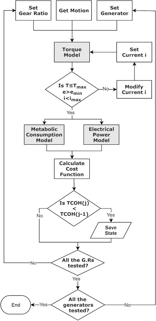
FIGURE 3. Block diagram of the optimization algorithm that ran through all the states and found the best one.
To demonstrate our optimization algorithm, we tested 11 different DC brushless motors that, according to our engineering judgment as well as the experience of others (Donelan et al., 2008), (Shepertycky and Li, 2015), could be good candidates. Thus, we tested motors from (Donelan et al., 2008) and other motors that met the following criteria: mass of less than 250 g, electrical power ranging from 10 to 100 W, and voltage ranging from 10 to 60 V (our system could not function with a higher input voltage). This framework could be used by developers of other devices to test different motors and find the best motor for their application. For convenience, all motors were manufactured by Maxon (Sachseln, Switzerland). They differed in their mechanical and electrical characteristics, as shown in Table 1.
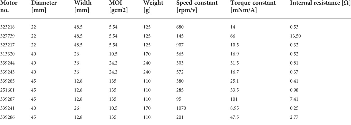
TABLE 1. Motors’ mechanical and electrical specifications.
2.4.5 Building and testing the energy harvester
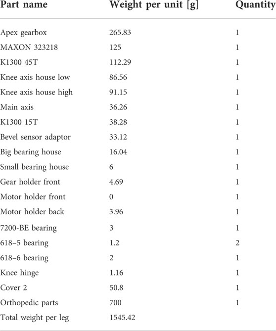
To evaluate our model, two exoskeletons, one for each leg, were built based on the optimization results (the list of the components and their masses is provided in Appendix B). Two experiments were then performed. The first was with a single male subject (1.8 m, 85 kg) walking with the device while a torque meter (mini 45, ATI, Apex, NC, United States) was installed at the knee joint (Appendix C).
This experiment aimed to validate our modeling predictions (torque profile and energy harvested). In the next experiment, we studied the effect of different harvesting levels on the change in metabolic effort. Four male subjects (181.5 ± 2.6 cm, 85.3 ± 7.5 kg, 28–32 years) wore two harvesters, one on each leg, with each device controlled separately (the torque meter was removed to reduce device mass). They walked on a treadmill at a speed of 1.3 m/s under six different conditions: mechanically disconnected (wearing the device as a dead weight) and five harvesting states (15%, 22.5%, 30%, 37.5%, and 50%), each one representing a ratio of resistance torque applied to the knee joint based on normal gait data (Shkedy Rabani et al., 2022). Each condition was applied for a duration of 7 min of walking, where the last 3 min of the condition were used to calculate the metabolic rate. Between each condition, there was a 5-min resting period. The order of the harvesting states was randomized. The subjects completed the experiment twice; the first session was for training purposes, allowing the subjects to get used to the device, while the second session is the one reported here. The time interval between the two sessions ranged from 1 to 3 weeks. The harvester controller was an embedded device that used the PIC24FJ32GA102 microcontroller to control the torque of the generator and to run the detection algorithm (which determined the harvesting phases based on the real-time knee joint angle). The microcontroller consumed approximately 0.25 W for its operation. Since a specific load-oriented voltage control loop has not been realized, and to prevent overvoltage when unloaded, a dumping resistor with autonomous control was used. We also used this resistor to calculate the electrical power output (average of the last 3 min). Further information on the harvesting system can be found in (Cervera et al., 2016), (Rubinshtein et al., 2014). Metabolic rates were measured using the Quark system (Cosmed, Rome, Italy). Figure 4 shows the experimental setup.
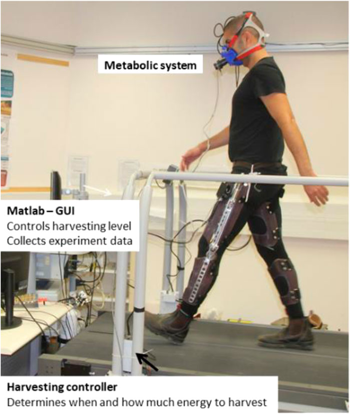
FIGURE 4. The experimental system included the Matlab graphical user interface (GUI), which sets the harvesting level and collects the experiment data; metabolic system; energy harvester for each leg; and harvesting controller for each leg, which determines when to harvest and how much (based on the harvesting level).
2.4.6 Statistical analysis
We first tested whether, for the group, there was an effect of condition (i.e., harvesting state) on electrical power and metabolic rate. Next, for each individual subject, we used their breath-to-breath data to determine whether there was an effect of condition on metabolic rate. In both cases, we used single-factor ANOVA with a post hoc Tukey Honest Significant Difference HSD test and a significance level of p less than 0.05.
3 Results and discussion
3.1 Optimization
The optimization process yielded the optimal gear ratio and torque profile to minimize the cost function (TCOH) for each of the motors. Figure 5 presents the results for motor no. 323218, which achieved the best TCOH. The comparison between the motors is presented in Table 2. Even though all the motors were considered good candidates for the device, there was approximately a six-fold difference in the value of the optimization cost function across the different models. The changes in gear and motor combination mass resulted in a difference of less than one metabolic W between the different combinations.
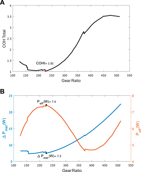
FIGURE 5. Optimization results for motor no. 323218. (A) The best possible TCOH as a function of gear ratio. (B) The best possible change in metabolic power, and the amount of electrical power produced, as a function of gear ratio.
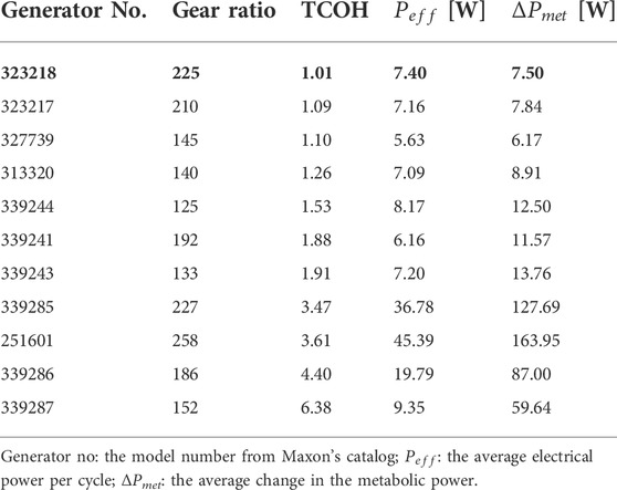
TABLE 2. Optimization results for each of the motors.
In the conceptual design used by the optimization, the generator is rigidly connected to the brace mechanism at all gait phases and causes mechanical torque resistance during the positive work phases (in these phases, more torque resistance will increase the metabolic effort). Thus, the optimization favors generators with low effective MOI (function of both the motor and the gear ratio), as this decreases the mechanical resistance during positive joint work phases, when the generator is not active (zero current; see Figure 6). Hence, the top seven generators had relatively low MOIs. The top three had the same motor design with different electrical properties. These results of preference for motors with a gear combination are in line with the changes that Shepertycky et al. (2021) made to improve their previous device (Shepertycky and Li, 2015) and the results from (Rubinshtein et al., 2012; Cervera et al., 2016). Further, it should be noted that the optimizations considered the user’s effort. Solutions such as higher gear ratios may produce more electricity, but they lower the conversion efficiency of the system, increasing the inertia and thus requiring more effort from users, especially in the non-harvesting phases of the gait. This was avoided by the optimization.
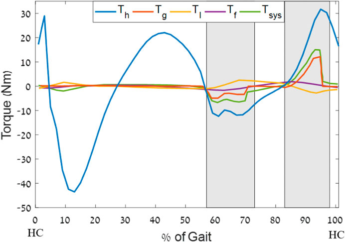
FIGURE 6. Optimal torque profile example for a 50% harvesting level (generator no. 323218), where
3.2 Model validation
A harvesting device was built using motor no. 323218 (EC-4pole 22 Ø22 mm) and a gear ratio of 243:1, with a 3:1 bevel gear and 81:1 planetary gear. To validate the system torque model, an external torque meter was mounted on the harvester. The torque meter readings were then compared with the harvesting torque profiles from the model. The comparison was performed for several torque profile levels and, for each level, over approximately 15 cycles of the subject walking at 1.3 m/s. These experiments revealed a goodness of fit between the model and the torque meter of R2 = 0.87 Figure 7. Further, two calculations were performed for the total efficiency of the device: 1) Calculated based on specifications of the two gears (Apex 85%, Bevel 95%) of the electrical harvesting system 88% (Cervera et al., 2016). Thus, this calculation results in approximately 71% efficiency. 2) Using the torque meter to calculate mechanical energy input, the electrical power-generated efficiency was calculated to be approximately 65%.
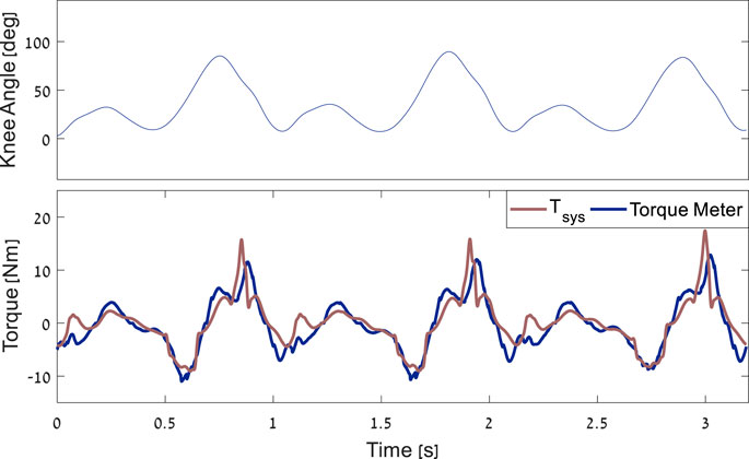
FIGURE 7. Example of the comparison between the torque meter results and the model over three gait cycles.
3.3 Experimental results
For all the subjects, an increase in the harvesting torque level resulted in an increase in electrical power output (Figure 8A), where the ANOVA showed that there was a significant difference in electrical power output between conditions (p < 0.05), and post hoc Tukey HSD tests revealed that there were significant differences only between non-neighboring conditions. For example, the 22.5% harvesting level was not significantly different from the 15% or the 30% levels, but it was different from the 37.5% and 50% levels. The metabolic change relative to walking with the device disconnected was calculated for each of the subjects at each of the harvesting levels (Figure 8B). The ANOVA results revealed that overall (i.e., across all subjects), the effect of the harvesting level on the metabolic change was significant, and the post hoc tests revealed that the 30% level was significantly different from the 50% condition. When testing the metabolic rate at the different experimental conditions for each of the subjects, the following results were obtained. For Subject 1, the 30% harvesting level (corresponding to the lowest value of metabolic change) was significantly different from all the other conditions. For Subject 2, the 15% condition was statistically different from the 22.5%, 30%, and 50% conditions but not from the 37.5% condition. For Subject 3, the 30% condition was different from all other conditions except 37.5%. For Subject 4, all the conditions were different from the 50% condition. Note that negative values in Figure 8B indicate that electrical energy was generated while the metabolic power (effort) was reduced (compared to the disconnected condition). These results suggest that the harvesting level of the device should be subject specific. This is in line with the findings of, which showed that different levels of harvesting resulted in different changes in metabolic power values for different individuals (Donelan et al., 2008), (Shepertycky and Li, 2015)]. As well as with the findings of, which showed that individual optimization of the actuation using the human-in-the-loop method could improve the performance of exoskeletons relative to a generic mode (Zhang et al., 2017), (Lee et al., 2018). Thus, future harvesters should customize their final torque profile using this method. Further, many exoskeletons that attach to the body are custom-made for each subject [e.g., 16], which improves the energy transfer between the exoskeleton and enhances users’ comfort.
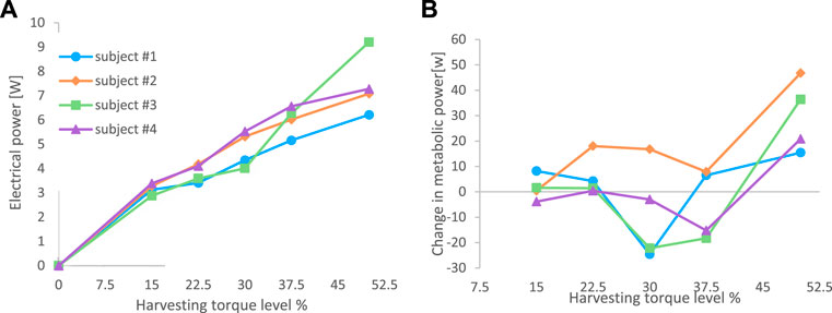
FIGURE 8. Results from the experiments on four subjects. (A) Electrical power output of the system for each of the subjects at six harvesting levels. (B) Metabolic change relative to walking with the device disconnected (dead weight). The figure data is in Appendix D.
Comparison of the model prediction and the average experimental results (Figure 9A) revealed that the harvesting energy was similar in both cases, albeit with slightly higher values for the experimental results at low harvesting levels. This could be explained by the fact that the device managed to harvest at a lower voltage than the limit in the simulation. Regarding the metabolic differences between the harvesting and mechanically disconnected conditions (Figure 9B), while the model predicted a continuous reduction in metabolic power with an increase in the harvesting level, the experimental results showed a complex shape with a minimum at 30% and a large increase in metabolic power at 50%.
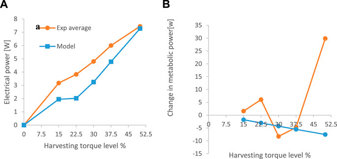
FIGURE 9. Comparison between the average results from the experiment and the predictions of the simulation. (A) electrical power harvested. (B) metabolic power.
3.4 Limitations and future work
In this study, we used a model based on the work of Margaria et al. (1968), which relates mechanical work performed by the body to metabolic rate. This model was evaluated using experimental data of walking on sloped and level ground and was found to be a good fit (R2 > 0.9) compared to more complex models that include muscle (Koelewijn et al., 2019). However, in our experiments, as was also observed by Collins et al. (2015), at some point there was an increase in metabolic rate as the device provided more assistance at the joint level. We believe that this could be due to several mechanisms. First, recent work shows that even with more complex models with muscle (Umberger et al., 2003) the simulation failed to find the same optimal assistance torque that was found in the experiments in (Franks et al., 2020). Second, as was also the case in previous studies (Uchida et al., 2016), (Dembia et al., 2017), in our optimization there is an assumption that the walking kinematics and kinetics do not change with the load. Yet, while this holds true for lower loads, for higher loads, there appears to be an effect of the load on the walking patterns at all joints (Donelan et al., 2008), (Shepertycky and Li, 2015). An alternative to the above method might be to use the experimental results to create a function that relates the level of harvesting to the change in metabolic power and to use this relation during the optimization for the design of the next device.
Regarding future work, Shepertycky et al. (2021) recently built and tested a device that reduced metabolic effort compared to walking without a device while producing 0.25 W of electricity from the late swing motion. The current device was unable to reduce the overall metabolic effort (i.e., walking with no device compared with walking with the activated device). However, the design (with the motor connected with no clutch mechanism) enabled harvesting energy during both flexion and extension. This enables more potential energy to be harvested, for example, in our 30% condition, in which the best for most of the subject. The device harvested an average electrical power of 4.8 W while reducing the metabolic power by 8.26 W compared to walking with the harvester as a dead weight. Using the framework proposed by Schertzer and Riemer et al. (2015), we found that in theory, a harvester with a mass of less than 0.5 kg could produce approximately 5 W, which is 40 times more than the best result achieved in (Shepertycky et al., 2021) and would reduce the metabolic effort. It should be noted that our current energy harvester is a prototype that was designed to test a concept. When using the device in these pilot experiments, we were able to generate an average of 12 W during walking at a torque level of approximately 80%. Thus, a design for 30% of this torque level could be achieved using a smaller motor and a lighter structure, as the force and torque would be smaller. A further reduction in the device’s mass could be achieved by using a material such as carbon fiber, which has a tensile strength-to-mass ratio that is between two and four times higher than the aluminum 7075 T6 that we employed. This means that a structure that could hold the same load would be two to four times lighter.
This study tested a knee energy-harvesting device that could generate electricity during the joint’s mechanical negative work phases of the gait, both at flexion and extension. Thus, it could harvest in K1, K3, and K4, as opposed to previous harvesters, which could only harvest during the late swing (K4, Figure 2). Our optimization preferred generators with effective low MOI. This is advantageous for designing with direct drive, as a one-way roller clutch with high MOI (Donelan et al., 2008; Shepertycky and Li, 2015) that might result in disengagement of the generator towards the end of the late swing phase. This disengagement is due to large kinetic energy stored that electrical harvesting needs to remove to slow down the angular velocity of the generator, at a rate needed to follow the angular velocity provided to the generator by the knee (Rubinshtein et al., 2012). Further, the highly effective MOI means that the system is designed for one specific gait and will not work as well in other conditions (e.g., slower walking steps or running). Thus, the direct-drive approach with low MOI should enable harvesting more energy and other conditions with more negative joint work than level walking (e.g., running) (Riemer et al., 2021). A recent development in exoskeletons is a device with regenerative braking (Zhu et al., 2019), which can harvest and return energy and provide assistance when the joint is performing either positive or negative work. Therefore, our results might support the effort to build exoskeletons that have a minimal need for external power yet can change their assistive torque profiles as needed.
4 Conclusion
In this study, we presented an optimization method for the design of an energy harvester system during level walking. This method enabled testing many different motor and gear combinations and could be used by developers of other devices to achieve the best design for their application. Further, our device enabled us to harvest energy from all gait phases and not only from late swing phase. Our experiments revealed that for all the subjects, there was at least one harvesting condition where the metabolic power required for generating electrical energy was close to zero or less than zero. These results suggest that a lighter, similar design might be able to improve user metabolic performance in the future.
Data availability statement
The raw data supporting the conclusion of this article will be made available by the authors, without undue reservation.
Ethics statement
The studies involving human participants were reviewed and approved by Ben-Gurion University of the Negev, Beer-Sheva, Israel. The patients/participants provided their written informed consent to participate in this study.
Author contributions
MG did the simulation and building the device and code for the controller, BL-A improve the design of the energy harvester and wrote code for the controller and performed the experimental work. AS help with some of the grant writing and advisor of MG and BL-A and CB-D worked on data analysis. RR wrote all the grants for funding was the initiator of the study worked with all the student as their advisor on simulation, design, manufacturing, control, running the experiment an analysis. All authors worked on the paper writing.
Funding
This study was partially supported by BSF (2011152) MAFAT and the Helmsley Charitable Trust through the Agricultural, Biological and Cognitive Robotics Initiative of Ben-Gurion University of the Negev and Israel ministry of science and technology.
Acknowledgments
We would like to thank Alon Cervera, Ze’ev Rubinshtein, Bar Halvani, and Nir Raviv as well as Prof. Mor Mordechai Peretz and Prof. Shmuel (Sam) Ben-Yaakov, who comprised the electrical engineering team that built and helped operate the electrical harvester and its controller. Thanks to Anat Shkedy Rabani for her help with the experiment.
Conflict of interest
The authors declare that the research was conducted in the absence of any commercial or financial relationships that could be construed as a potential conflict of interest.
Publisher’s note
All claims expressed in this article are solely those of the authors and do not necessarily represent those of their affiliated organizations, or those of the publisher, the editors and the reviewers. Any product that may be evaluated in this article, or claim that may be made by its manufacturer, is not guaranteed or endorsed by the publisher.
References
Browning, R. C., Modica, J. R., Kram, R., and Goswami, A. (2007). The effects of adding mass to the legs on the energetics and biomechanics of walking. Med. Sci. Sports Exerc. 39 (3), 515–525. doi:10.1249/mss.0b013e31802b3562
Cervera, A., Rubinshtein, Z., Gad, M., Riemer, R., and Peretz, M. M. (2016). Biomechanical energy harvesting system with optimal cost-of-harvesting tracking algorithm. IEEE J. Emerg. Sel. Top. Power Electron. 4 (1), 293–302. doi:10.1109/JESTPE.2015.2514079
Collins, S. H., Bruce Wiggin, M., and Sawicki, G. S. (2015). Reducing the energy cost of human walking using an unpowered exoskeleton. Nature 522 (7555), 212–215. doi:10.1038/nature14288
Dembia, C. L., Silder, A., Uchida, T. K., Hicks, J. L., and Delp, S. L. (2017). Simulating ideal assistive devices to reduce the metabolic cost of walking with heavy loads. PLoS One 12 (7), e0180320–25. doi:10.1371/journal.pone.0180320
Donelan, J. M., Li, Q., Naing, V., Hoffer, J. A., Weber, D. J., and Kuo, A. D. (2008). Biomechanical energy harvesting: Generating electricity during walking with minimal user effort. Sci. (80) 319 (5864), 807–810. doi:10.1126/science.1149860
Franks, P. W., Bianco, N. A., Bryan, G. M., Hicks, J. L., Delp, S. L., and Collins, S. H. (2020). Testing simulated assistance strategies on a hip-knee-ankle exoskeleton: A case study. Proc. IEEE Ras. EMBS Int. Conf. Biomed. Robot. Biomechatronics 2020, 700–707. doi:10.1109/BioRob49111.2020.9224345
Koelewijn, A. D., Heinrich, D., and van den Bogert, A. J. (2019). Metabolic cost calculations of gait using musculoskeletal energy models, a comparison study. PLoS One 14 (9), e0222037–19. doi:10.1371/journal.pone.0222037
Lee, S., Kim, J., Baker, L., Long, A., Karavas, N., Menard, N., et al. (2018). Autonomous multi-joint soft exosuit with augmentation-power-based control parameter tuning reduces energy cost of loaded walking. J. Neuroeng. Rehabil. 15, 66. doi:10.1186/s12984-018-0410-y
Li, Q., Naing, V., and Donelan, J. M. (2009). Development of a biomechanical energy harvester. J. Neuroeng. Rehabil. 6 (1), 22–12. doi:10.1186/1743-0003-6-22
Margaria, R. (1968). Positive and negative work performances and their efficiencies in human locomotion. Int. Z. Angew. Physiol. Einschl. Arbeitsphysiol. 25 (4), 339–351. doi:10.1007/BF00699624
Martin, J.-P., Shepertycky, M., Liu, Y.-F., and Li, Q. (2016). Lower limb-driven energy harvester: Modeling, design, and performance evaluation. J. Med. Device. 10 (4), 041005. doi:10.1115/1.4033014
Niu, P., Chapman, P., Riemer, R., and Zhang, X. (2004).Evaluation of motions and actuation methods for biomechanical energy harvesting Proceeding PESC Record - IEEE Annual Power Electronics Specialists Conference, 20-25 June 2004, Aachen Germany, 3. IEEE. doi:10.1109/PESC.2004.1355442
Riemer, R., Nuckols, R. W., and Sawicki, G. S. (2021). Extracting electricity with exosuit braking. Sci. (80) 372 (6545), 909 LP–911. doi:10.1126/science.abh4007
Riemer, R., and Shapiro, A. (2011). Biomechanical energy harvesting from human motion: Theory, state of the art, design guidelines, and future directions. J. Neuroeng. Rehabil. 8 (1), 22. doi:10.1186/1743-0003-8-22
Rubinshtein, Z., Peretz, M. M., and Riemer, R. (2014). Biomechanical energy harvesting system with optimal cost-of-harvesting tracking algorithm. Conf. Proc. - IEEE Appl. Power Electron. Conf. Expo. - APEC,4 3105–3109. doi:10.1109/APEC.2014.6803748
Rubinshtein, Z., Riemer, R., and Ben-Yaakov, S. (2012). Modeling and analysis of brushless generator based biomechanical energy harvesting system.In Proceeding IEEE Energy Convers. Congr. Expo. ECCE,IEEE.15-20 September 2012.Raleigh, NC, USA 2784–2789. doi:10.1109/ECCE.2012.6342380
Schertzer, E., and Riemer, R. (2015). Harvesting biomechanical energy or carrying batteries? An evaluation method based on a comparison of metabolic power. J. Neuroeng. Rehabil. 12 (1), 30. doi:10.1186/s12984-015-0023-7
Schertzer, E., and Riemer, R. (2014). Metabolic rate of carrying added mass: A function of walking speed, carried mass and mass location. Appl. Ergon. 45 (6), 1422–1432. doi:10.1016/j.apergo.2014.04.009
Shepertycky, M., Burton, S., Dickson, A., Liu, Y. F., and Li, Q. (2021). Removing energy with an exoskeleton reduces the metabolic cost of walking. Sci. (80-. ) 372, 957–960. doi:10.1126/science.aba9947
Shepertycky, M., and Li, Q. (2015). Generating electricity during walking with a lower limb-driven energy harvester: Targeting a minimum user effort. PLoS One 10 (6), e0127635. doi:10.1371/journal.pone.0127635
Shkedy Rabani, A., Mizrachi, S., Sawicki, G. S., and Riemer, R. (2022). Parametric equations to study and predict lower-limb joint kinematics and kinetics during human walking and slow running on slopes. PloS one 18 (8), e0269061. doi:10.1371/journal.pone.0269061
Soule, R. G., and Goldman, R. F. (1969). Energy cost of loads carried on the head, hands, or feet. J. Appl. Physiol. 27 (5), 687–690. doi:10.1152/jappl.1969.27.5.687
Stuempfle, K. J., Drury, D. G., and Wilson, A. L. (2004). Effect of load position on physiological and perceptual responses during load carriage with an internal frame backpack. Ergonomics 47 (7), 784–789. doi:10.1080/0014013042000193264
Uchida, T. K., Seth, A., Pouya, S., Dembia, C. L., Hicks, J. L., and Delp, S. L. (2016). Simulating ideal assistive devices to reduce the metabolic cost of running. PLoS One 11 (9), e0163417–19. doi:10.1371/journal.pone.0163417
Umberger, B. R., Gerritsen, K. G. M., and Martin, P. E. (2003). A model of human muscle energy expenditure. Comput. Methods Biomech. Biomed. Engin. 6 (2), 99–111. doi:10.1080/1025584031000091678
Zhang, J., Fiers, P., Witte, K. A., Jackson, R. W., Poggensee, K. L., Atkeson, C. G., et al. (2017).Human-in-the-loop optimization of exoskeleton assistance during walking, Science., 1284. June, 1280–1284. doi:10.1126/science.aal5054
Appendix A: BLDC- DC conversion
The following set of equations defines the DC equivalent circuit constants of the generator:
where
where
where
The external load is bound to this equivalent circuit as well, and the transformation is given by
where
Appendix B: Masses of the device components
Appendix C: Mounting the torque meter
In order to verify the system’s torque model, we needed to be able to measure the torque that the system applied to the knee during a walking gait while the energy harvester was harvesting energy. The torque meter is a heavy component and therefore needed to be detachable so that it could be removed once the model validation was completed. The torque meter used in the study was the ATI mini 45, which is a 6DOF load cell. To mount the torque meter, we designed an adaptor that we mounted on the torque meter so that the bevel gear could be connected to it (Figure 10).
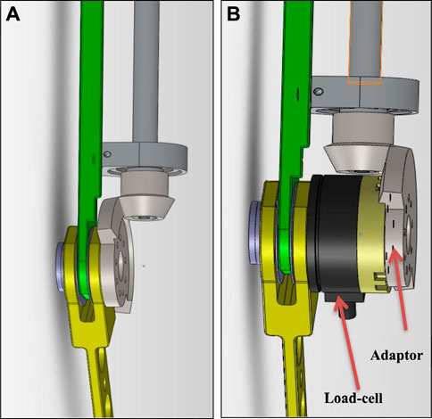
FIGURE 10. Illustration of the method of mounting the torque meter. (A) Normal use without the torque meter. (B) Configuration with the torque meter attached.
Appendix D: Experiment data in table form
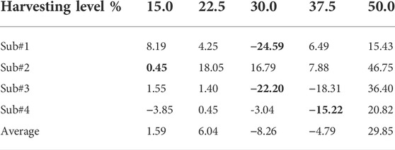
TABLE D1. Metabolic power differences (Harvesting-Disconnected); bold indicates the lowest number for each subject.
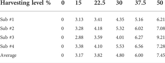
TABLE D2. Electrical power produced at each harvesting level.
Keywords: biomechanical knee energy harvester, exoskeleton, reduced effort, simulation, design optimization
Citation: Gad M, Lev-Ari B, Shapiro A, Ben-David C and Riemer R (2022) Biomechanical knee energy harvester: Design optimization and testing. Front. Robot. AI 9:998248. doi: 10.3389/frobt.2022.998248
Received: 19 July 2022; Accepted: 25 August 2022;
Published: 05 October 2022.
Edited by:
Qiongfeng Shi, National University of Singapore, SingaporeReviewed by:
Zhiran Yi, Shanghai Jiao Tong University, ChinaLong Liu, Northwestern Polytechnical University, China
Copyright © 2022 Gad, Lev-Ari, Shapiro, Ben-David and Riemer. This is an open-access article distributed under the terms of the Creative Commons Attribution License (CC BY). The use, distribution or reproduction in other forums is permitted, provided the original author(s) and the copyright owner(s) are credited and that the original publication in this journal is cited, in accordance with accepted academic practice. No use, distribution or reproduction is permitted which does not comply with these terms.
*Correspondence: Raziel Riemer, cnJpZW1lckBiZ3UuYWMuaWw=