 Shiva Pandiri
 Jacob Murphy2
 Kamran Fouladi
 Saeed Tiari
- 1Mechanical Engineering Department, Gannon University, Erie, PA, United States
- 2Biomedical, Industrial and Systems Engineering Department, Gannon University, Erie, PA, United States
- 3Mechanical Engineering Department, Widener University, Chester, PA, United States
- 4Biomedical Engineering Department, Widener University, Chester, PA, United States
The global shift towards renewable energy to replace fossil fuels has led to exploring thermal energy storage techniques employing phase change materials (PCM), known as latent heat thermal energy storage (LHTES). Renewable energy sources such as solar and wind have limitations due to their unpredictable nature and thus require adequate storage during times of intermittency. PCMs offer a high energy storage density, however, their thermal performance is limited by their low thermal conductivity. This is leading researchers to investigate passive heat transfer enhancement techniques, such as nanoparticle dispersion, porous matrices, heat pipes, and fins, to improve heat transfer within PCMs. Recent studies have primarily focused on the numerical analysis of branched fins, leaving a significant gap in experimental validation. This study addresses this gap by providing a comprehensive experimental evaluation of the thermal performance of a LHTES system enhanced by branched fins, The performance of various fin configurations is compared during both charging and discharging processes. The present study takes a novel approach in comparing performance of radial fins, Y-fins, and snowflake fins in two sets of cases: four-fin and six-fin arrangements, which are compared to a baseline of a zero-fin configuration. All four-fin arrangements contain the same volume of copper, and all six-fin arrangements contain more copper than the four-fin arrangements. The fin configurations are compared based on charging and discharging times and the system energy response. The comparisons indicate that all branched fins configurations resulted in significant reductions in charging and discharging times compared to the benchmark. For four-fin arrangements, radial fins show a decrease of 81.52% and 63.45%, Y-fins show a reduction of 85.97% and 73.64% and snowflake fins show a reduction of 86.3% and 73.2% in charging and discharging times, respectively. For six-fin arrangements, radial fins show a reduction of 89.76% and 76.87%, Y-fins show a reduction of 91.63% and 83.03%, and snowflake fins show a reduction of 91.61% and 86.14% reduction in charging and discharging times, respectively.
1 Introduction
Countries are pursuing renewable energy due to concerns about environmental degradation and the limited availability of fossil fuels. Based on information from the Energy Outlook 2022 (U.S. Energy Information Administration, 2023), renewable energy is a thriving concept as an alternative to fossil fuels. By 2050, renewable energy is projected to be the most significant power source and will have the highest rate of growth (Siddik et al., 2023).
The main concern with most renewable energy sources is the intermittency of the power supply (Zycher, 2019). Therefore, developing various energy storage technologies is crucial in resolving this challenge of fulfilling energy requirements. One of the energy storage methods (Cabeza, 2022a; Cabeza L. F. 2022) that have shown promise in solar applications is thermal energy storage (Kumar et al., 2023). Presently, there are three primary methods to store thermal energy. In sensible heat thermal energy storage (Niksiar et al., 2024; Vijjapu and Tiwari, 2022), the medium does not undergo a phase change to store and release energy. In latent heat thermal energy storage (LHTES) (Zhang and Wang, 2018), the medium undergoes a phase change for charging and discharging to store and release energy. The third method is thermochemical energy storage (Zamengo et al., 2015), where heat is employed in chemical reactions to store the energy as chemical potential, and the energy is released when the reverse chemical reaction occurs.
LHTES brings attention to the use of phase change in thermal energy storage due to the high energy storage density and the minor temperature variations. With this technique, a relatively small volume of a phase change material (PCM) can store a significant amount of heat through the phase change process. PCMs have been identified as promising candidates for LHTES due to their high energy storage density and isothermal energy storage capabilities. However, the low thermal conductivity of PCMs presents a challenge for efficient heat transfer, particularly during the charging and discharging processes. Passive heat transfer enhancement techniques, such as heat pipes (Maghrabie et al., 2022), nanoparticle dispersion (Tofani and Tiari, 2021), porous matrices (Kiwan and Al-Nimr, 2001), and extended surfaces and fins (Ao et al., 2023; Narkhede et al., 2024), have been developed to improve heat transfer within PCMs and the thermal performance of LHTES systems. Extended surfaces and fins have been shown to improve heat transfer within PCMs significantly (Tiari and Hockins, 2021). Fins increase the surface area available for convective heat transfer between the PCM and the heat transfer fluid (HTF), leading to enhanced heat transfer rates (Mobedi et al., 2022). According to a literature review by Teggar et al. (2021), the use of fins and extended surfaces is the most popular method to increase the effectiveness of heat transfer within LHTES systems. Fin geometries that are noted in their study include longitudinal, radial, axial, spiral, and other more unique variations. It was indicated that the geometry of the fins can greatly impact the rate of heat transfer. Moreover, the goal when choosing a fin geometry is to maximize the surface area for heat transfer between the PCM and HTF, considering the shape of the container.
One way to increase the surface area is by increasing the number of fins present in the system. Tiari et al. (2021) conducted a numerical study on the effect of annular fins on an LHTES system with comparing number of fins in the system. The LHTES system was tested with a cylindrical container filled with RT55 PCM and a central pipe carrying the HTF. Two cases were compared: one with ten annular fins and one with twenty annular fins of uniform length. Between the two cases, the best results came from the configuration with twenty fins, reducing the overall time by 76.3% for the charging and discharging processes, compared to a benchmark case with no fins.
There are other ways that fins can be modified to increase the efficiency of an LHTES system. In a numerical study, Sharifi et al. (2011) investigated the impact of fin lengths, fin thicknesses, and numbers of fins on melting time of a PCM. The study found that all variations considered significantly reduced melting times compared to a no-fin benchmark. Importantly, the results pointed to rapid melting rates at initial stages of the process due to conduction as the primary mode of heat transfer followed by a slower but continued melting at later stages as convection becomes the dominant mode. This means that any chosen fin configuration needs to allow for adequate flow of the PCM to facilitate the best rates of heat transfer. This phenomenon was later investigated in an experimental study by Tiari et al. (2022) that considered variable fin lengths. In a vertical cylindrical container, fins with lengths gradually increasing from top to bottom reduced charging time by 89.45% and discharging time by 77.41%, outperforming fins with lengths decreasing from top to bottom.
More recent developments include unique variations of fin geometry, including bifurcated fins. Yu et al. (2022) established in a numerical simulation that Y-fins can improve the rate of heat transfer in LHTES systems. Their best fin design had a width ratio of 1/3 the length ratio and a branch angle of 64.49°. Their study showed that Y-fins provide a more uniform temperature field and a 50.9% shorter discharge duration than straight fins. Zhang et al. (2020) assessed the performance of tree-like fins in a two-dimensional model of an LHTES system. While the tree fins improved melting time by only 4.4%, solidification time was improved by 66.2% over radial fins. Al-Shuwaili et al. (2023) numerically evaluated branching fractal fins with angles of the branches ranging from 10°–180°. It was determined that all branch angles improved the thermal performance, but 140° reduced melting and solidification times the most compared to the non-finned simulation.
The snowflake fin configuration is another shape that has garnered significant attention. Sheikholeslami et al. (2016) performed a numerical simulation on process acceleration and improved energy storage capabilities. The results suggested that using snowflake fins in PCM is more effective than adding nanoparticles to the PCM in enhancing the discharge rate of the thermal energy storage system. On their study the fastest energy recovery process was achieved by using the snowflake fins in PCM. Zhang et al. (2022) studied the effects of a snowflake like configuration with varying branched fin lengths. The study simulated eight fins, each with three branches at 45° angles, with four different configurations of branched fin lengths. The branched fin configurations reduced melting time up to 80.65% when compared to the simulation with no fins. A study performed by Luo et al. (2023) performed experimental and numerical analysis on traditional radial snowflake fins, as well as four novel snowflake shapes designed to reduce area between fins. The optimal snowflake design reduced total charging and discharging time by 45.15% when compared to radial fins. In a numerical study by Ren et al. (2023), novel snowflake shapes were optimized to enhance the natural convection caused by the melting of the PCM in a horizontal LHTES system. It was found that concentrating the snowflake fins at the bottom of the cylinder greatly increases the velocity of natural convection, and an angle of separation of 40° was found to be the optimal combination natural convection and conduction, decreasing total melting time by 15.9% compared to traditional snowflake fins.
The current work focuses on an experimental investigation of the effect of branched fins on the thermal performance of LHTES systems, addressing the gap in experimental data in this domain. Unlike previous studies, which are predominantly numerical, our research offers experimental analysis for two branched fin configurations: (1) four-fins and (2) six-fins. Each configuration is evaluated with three distinct geometric shapes - radial, Y-shaped, and snowflake fins - and compared to a zero-fin configuration within the LHTES system. The experiments involve charging and discharging the system with Rubitherm RT-55 as the PCM in a vertical cylindrical container. A key novelty of this work lies in using the same amount of copper to fabricate various fin configurations, including radial, Y-shaped, and snowflake geometries, enabling a fair comparison of their thermal performance. The amount of copper in four and six-fin cases are 134.55 cm3, and 201.83 cm3, respectively. Each fin configuration is evaluated for both charging and discharging phases, with fin effectiveness determined by the reduction charging and discharging times relative to the zero-fin benchmark case.
The findings of this study have significant implications for the design and optimization of LHTES systems. While the novelty of this research lies in the experimental evaluation of branched fin configurations, its practical applications are equally important. As renewable energy sources such as solar and wind become more prevalent, the intermittency of their energy production poses a challenge for reliable energy supply. LHTES systems, with their ability to store energy in PCMs, can play a critical role in addressing this issue by providing a means to store excess energy during periods of high production and release it during periods of low production. The optimization of these systems, as demonstrated in this study, can help enhance the efficiency of renewable energy storage. Branched fins offer a promising approach to improving thermal performance, making them ideal for real-world applications in solar thermal systems, industrial waste heat recovery systems, and residential renewable energy systems.
2 Materials and methods
2.1 Apparatus and experimental methods
The main components of the LHTES system in the present study include a container that houses the PCM, a heat exchanging pathway that circulates either heated or cooled HTF through the PCM container, as well as thermocouples (TCs) and resistance temperature detectors (RTDs) that allow for the temperature at various points within the PCM to be measured for analysis. The schematic of the LHTES system, as well as the experimental setup used in this study, are shown in Figure 1.
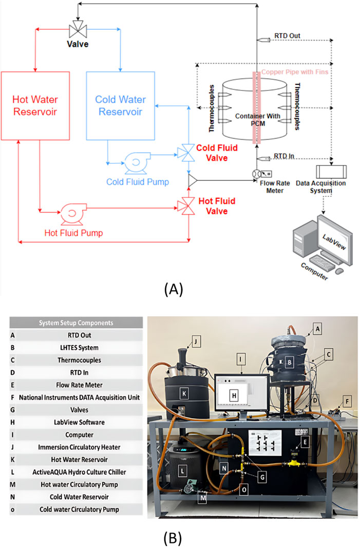
Figure 1. (A) LHTES system schematic and (B) experimental setup with labeled components.
The PCM container measures 30.5 cm in height, 19.05 cm outer diameter, and 1.27 cm wall thickness made of clear cast acrylic (McMaster-Carr, 2024c) with top and bottom of the container covered with 1.27 cm thick acrylic sheets with a diameter of 20.32 cm, holds 6 kg of PCM for every test. Flexible rubber foam insulation (McMaster-Carr, 2024b), 2.54 cm (1 inch) thick, is wrapped around the outside of the container to minimize heat loss to the surroundings. A concentric copper pipe inside this container with a 2.54 cm diameter allows for the controlled unmixed circulation of HTF through the PCM container. Copper is chosen to construct the central pipe and the fins, as it is simple to manufacture and highly thermally conductive. Due to its safe melting point, high latent heat of fusion, and relatively minimal volume change during the phase change, Rubitherm RT-55 is used as the PCM. The thermophysical properties of RT-55 and copper are shown in Table 1.
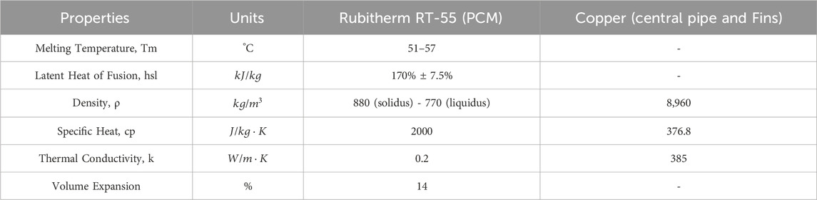
Table 1. Thermophysical properties of Rubitherm RT55 (Rubitherm, 2024) and copper (McMaster-Carr, 2024a).
The LHTES system has two separate HTF circulation loops for charging and discharging purposes and a central pipe within the PCM container. The 26.50 L water reservoir used to store hot water for the charging process, where HTF is heated by an immersion circulation heater (Anova Cullinary, 2024). The heater has an accuracy of ±0.5°C. Rubber foam insulation is wrapped around the hot water reservoir, similar to the PCM container, to minimize heat loss to the surroundings. A Grundfos (2024) circulatory pump draws hot water from the reservoir and circulates it back through a copper pipe that runs through the LHTES container, returning it to the reservoir. For charging, the PCM is considered ready for testing when all TCs reach a temperature of 21 °C, and the HTF is circulated at 70°C with a flow rate of 7.57 L/min (2 GPM). Discharging test is similar to the charging test, except that the ActiveAQUA submersible pump (Hydrofarm, 2024) pumps the cold HTF from a 75.70 L cold water reservoir after it is chilled by an ActiveAQUA Hydroculture 186 W (0.25 hp) chiller (Hydrobuilder, 2024). The chiller has an accuracy of ±1°C. For discharging, the PCM is considered ready for testing when all TCs reach a temperature of 56 °C, and the HTF is circulated at 20°C with a flow rate of 3.79 L/min (1 GPM). A three-way ball valve is used to direct either the hot or cold HTF to flow through the PCM container depending on the cycle being tested. A Blue White Industries (2023) paddle wheel flow meter is used to gauge the HTF flow rate in gallons per minute (GPM) during each test.
All cases are run at room temperature of 21°C, and the room temperature is monitored by a digital thermometer. Nine k-type thermocouples with an uncertainty of ±0.5°C (Omega, 2024a) are inserted at different heights and depths of the PCM container are used to measure the temperature of the PCM in response to the charging and discharging cycles, as shown in Figure 2. The thermocouples are positioned around the central pipe in three vertical sets, each at 0, 90, and 180° apart clockwise. The thermocouples’ three-level heights are labeled A, B, and C, and each vertical group was labeled 1, 2, and 3. Group 1 thermocouples are placed closer to the central pipe, the Group 2 thermocouples are placed in the middle between the copper pipe and the container wall, and the Group 3 thermocouples are positioned closer to the container wall. The first group of thermocouples, designated TC1, TC4, and TC7, are placed 0.64 cm from the center pipe. The thermocouples TC2, TC5, and TC8 in the second set are placed 4.15 cm away from the central pipe. The third set of thermocouples, TC3, TC6, and TC9, are last and situated 7.62 cm from the central pipe. The heights of thermocouples TC1–TC3, TC4–TC6, and TC7–TC9 from the bottom of the container are 20.32 cm, 12.7 cm, and 5.08 cm, respectively. At the entrance and exit of the central HTF pipe, two 100-Ω Class A RTDs with an accuracy of ±0.29°C at 70°C and ± 0.19°C at 20°C (Omega, 2024b) are used to measure the temperature of the HTF. To facilitate further data analysis, all data is sent to NI LabVIEW software (National Instruments, 2023a) using the National Instruments (2023b) cDAQ-9188 linked to the thermocouples and RTDs. A computer running NI LabVIEW is connected to the data-collecting equipment, which records temperatures every 5 s while testing.
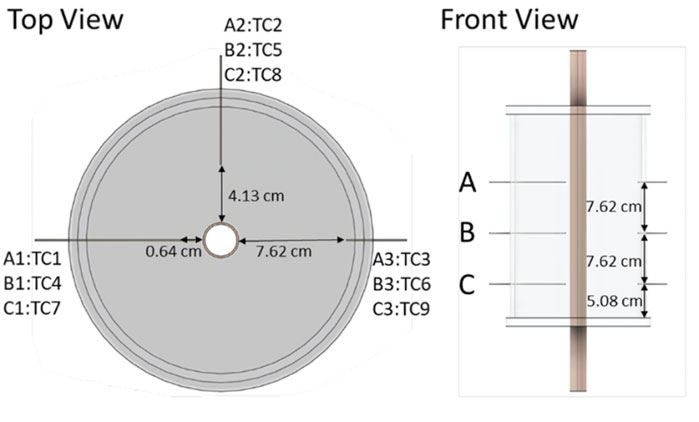
Figure 2. LHTES schematic with thermocouple locations.
2.2 Fin configurations
In the present study, three fin configurations with varying degree of branching are investigated with four and six fins arrangement. These fin configurations include radial fins, Y-fins, and snowflake fins. The increase in the level of branching aims to increase the surface area and heat penetration without increasing the volume of copper. The same amount of copper utilized for each fin configuration should allow for the most accurate comparison between cases.
The four-fin configurations were attached to a 2.54 cm hollow copper pipe with a length of 50.8 cm; the radial fins are 7.62 cm wide and 27.94 cm long with a thickness of 0.158 cm. Four fins are attached to the central pipe with 90° separation between each fin. The Y-fins and snowflake fins are based on radial fins. Y-fins structure, as shown in Figure 3, consists of radial fins of width 3.81 cm and thickness of 0.158 cm with two branches at the tip with a thickness of 0.080 cm and width of 3.81 cm, both with a height of 27.94 cm. Snowflake fins are a combination of four radial fins with 0.080 cm thickness with a width of 7.62 cm and branches with a width of 3.81 cm and thickness of 0.080 cm attached to the radial fins 3.81 cm from the center. The height of the branched fins is 27.94 cm. All branched configurations have branch angles of 90°. The geometries of the four-fin configurations are shown in Figure 3A.
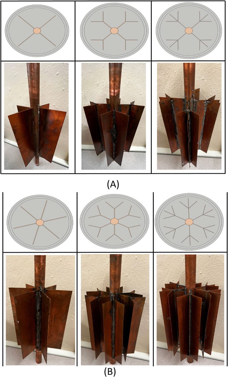
Figure 3. Top view and picture of (A) four fin and (B) six fin configurations.
The dimensions of each radial, Y, and snowflake fin in the six-fin configurations is equal to their respective four-fin configuration. The two additional fins result in the six-fin configurations having 50% increased volume of copper than the four-fin arrangements. All six-fin configurations are attached to the central pipe with 60° separation between each fin. The geometries of the six-fin configurations are shown in Figure 3B.
3 Results and discussion
3.1 Benchmark case
A comparative analysis was conducted on the total charging and discharging times for two cases with different numbers of fins, each featuring three configurations. These results were compared to a benchmark scenario where no fins were attached to the central pipe. Charging and discharging times, as well as total complete cycle times for each configuration can be seen in Figure 4A for four fin configurations, and Figure 4B for six fin configurations. The benchmark case had a charging time of 47.47 h and a discharging time of 41.43 h.
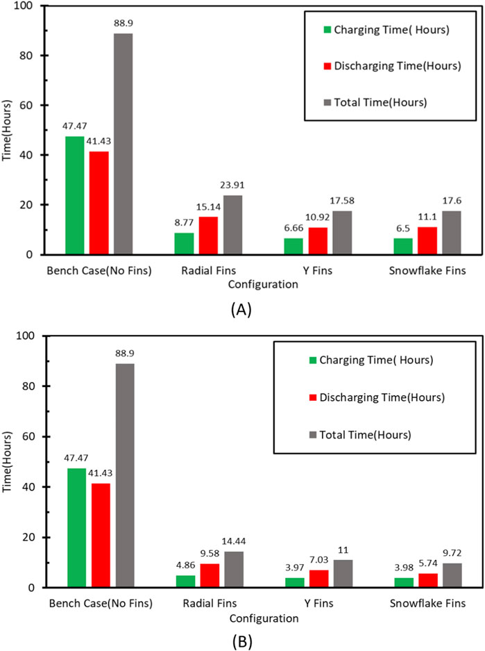
Figure 4. Comparison of total processing times for (A) four-fin case and (B) six-fin configurations.
The PCM temperature distribution for the benchmark case during the charging and discharging processes is illustrated in Figure 5. In Figure 5A, the thermocouples closest to the central pipe (TC1, TC4, and TC7) experience an initial rapid temperature increase during the charging process. Subsequently, the temperature of the PCM rises from the bottom of the container and moves upward due to the dominance of conduction in the early stage of the cycle. As the PCM melts, natural convection begins, and the higher temperature and lower density molten PCM moves upward, causing the temperatures of TC4 and TC7 to become nearly equivalent to TC1 due to the lower temperature and higher density PCM sinking. The remaining thermocouples exhibit similar behavior. After 7 h of testing, TC1, TC4, and TC7 exhibit similar temperatures, with TC1 gradually increasing, while TC4 and TC7 experience slower temperature increases. After 3 hours of testing, the temperature of the thermocouples at the bottom of the container increase rapidly. As time increases, the rate of temperature change decreases. This is due to the decreased temperature difference between the HTF and PCM, which decreases the heat transfer rate and slows the melting process. The heat transfer rate and the PCM temperature slope increase upon the onset of natural convection, causing the thermocouples nearest to the outer wall of the container (TC3, TC6, and TC9) to warm up. In general, the phase change of the RT55 starts at around 51°C, as per the manufacturer’s thermophysical properties. During the charging process, the melting of PCM is gradual. At the end of each charging experiment, the PCM was visually confirmed to be fully melted. However, the temperature of the PCM varied within the container. Specifically, the temperature at the top of the container ranged from 59°C to 60°C, while the temperature of the PCM at the bottom of the container remained at around 55°C. This temperature gradient is a result of the buoyancy effect, where molten PCM with higher temperature rises due to its lower density, creating a stratified temperature distribution. These observations have been consistent across all charging tests.

Figure 5. Benchmark case temperature distribution during (A) charging and (B) discharging.
In Figure 5B, the PCM temperature distribution for the benchmark case during the discharging process is shown. The PCM in the vicinity of the HTF pipe (TC1, TC4, TC7) initially experienced the most significant temperature drop. The PCM further away the HTF pipe and towards the outer wall of the container (TC3, TC6, TC9) exhibits a more rapid temperature decrease than the PCM between the central pipe and outer wall (TC2, TC5, TC8) during the initial stages of the test. Despite a relatively thick layer of insulation, the PCM located closer to the exterior of the container experiences significant temperature differences due to heat loss to the surroundings. At 24 h, TC3, TC6, and TC9 align with TC2, TC5, and TC8. Natural convection and the substantial temperature differential between the PCM and HTF result in a rapid temperature drop at the start of the discharging operation. The temperature gradient and heat transfer rate decrease as the PCM solidifies, causing a reduction in the temperature distribution slope. During the charging and discharging processes, the temperature difference between the RTD intake and output is typically less than 1°C–2°C. As the process continues, the temperature difference narrows, and the scale of the graphs shown in Figure 5 allows for visual distinction.
3.2 Four-fin configurations
The relatively low thermal conductivity of the PCM reduces the rate of conduction. Adding the fins to the central pipe significantly increases the heat transfer rate to or from the system and reduces the system’s charging and discharging times. Convection, as opposed to conduction which drives the discharging process (Tiari et al., 2016), is the primary driving force during charging (Tiari et al., 2015). Compared to the case without fins, the increased interfacial surface area and thermal penetration between the HTF and PCM in the cases assisted with fins cause a significant reduction in charging and discharging periods. The system charging and discharging periods are reduced more when it is enhanced with four Y-fins and four snowflake fins than with four radial fins. Generally, Y and Snowflake fins configurations show similar performance because both cases provide a greater interfacial surface area than the radial fins. This allows for a lower thermal resistance between the HTF and the PCM and a higher heat transfer rate to the system. Therefore, the charging and discharging time of the snowflake and Y-fins are shown to be similar. Importantly, the additional branch in snowflake configuration, compared to the Y-fins, offers minimal heat transfer enhancement. Consequently, the benefit of adding this section of fin is limited.
3.2.1 Four radial fins configuration
The case assisted with four radial fins takes 8.77 h to charge fully and 15.14 h to discharge. Compared to the benchmark case, this represents an 81.52% and 63.45% reduction in charging and discharging, respectively. Figure 6 depicts the PCM temperature distribution for the charging and discharging of the four-radial fin design. The PCM temperature distribution during the charging process illustrated in Figure 6A is similar to the benchmark scenario, however, the time required for completely melting the PCM is greatly reduced. This accelerated melting can be attributed to enhanced heat transfer from the HTF to the PCM due to the fins. Initially, conduction dominates, allowing heat to transfer rapidly from the HTF to the PCM, raising the temperature close to the melting point. As the PCM melts, natural convection becomes the dominant mechanism, with the molten PCM rising towards the top of the container. This convection significantly accelerates the melting process by improving heat distribution within the PCM. At the beginning of the experiment, the temperature increase is observed in TC4 and TC7 before TC1, which is consistent with the benchmark case. This pattern is evident in all finned cases. The thermocouples at the bottom of the container, TC7-9, exhibit signs of natural convection starting earlier in the experiment than the benchmark case due to a significant temperature spike early on.
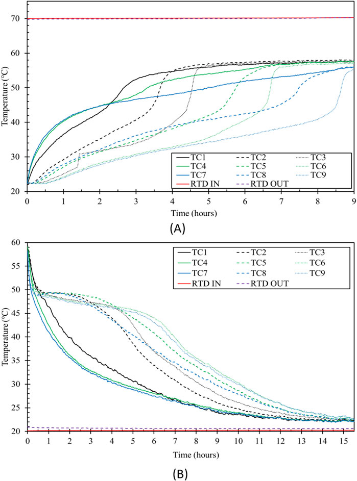
Figure 6. Four radial fin configuration PCM temperature distribution during (A) charging and (B) discharging.
As shown in Figure 6B; during the discharging test, the thermocouples closest to the container wall, such as TC3, TC6, and T9, decrease in temperature at a lower rate than those closer to the fins which is comparable to the benchmark scenario. This is because fins provide increased conduction heat transfer. At the start of the test, TC7 temperature drops, followed by TC4, TC1, and then levels off. This pattern is similar to the benchmark case.
3.2.2 Four Y-Fin configuration
It takes 6.66 h to charge fully and 10.92 h to discharge for the case assisted by four Y-fins. Compared to the benchmark, this represents an 85.97% and 73.64% reduction in charging and discharging, respectively. Figure 7 depicts the PCM temperature distribution for charging and discharging with the four Y-fin design. The enhancement is made to increase the surface area that the fins have in contact with the PCM, increasing the rate of heat transfer. For charging, Figure 7A, the thermocouples TC1, TC4, and TC7 seem to follow a similar trend as in the case with four radial fins. TC3 increases after 30 min of test to 35 °C rapidly, then the rate of temperature increase slows down, which shows convection followed by conduction. TC2 shows similar behavior to TC3 but gradually increases its temperature after 1 h of testing. TC6 and TC5 follow similar behavior to TC3 and TC2. TC8 and TC9 increase in a manner that suggests natural convection is the dominant factor in the heat transfer for this region of the container after the initial conduction-dominant stage.
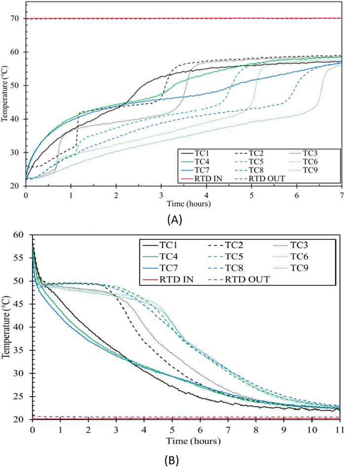
Figure 7. Four Y-fin configuration PCM temperature distribution during (A) charging and (B) discharging.
For discharging, shown in Figure 7B, the plateau looks similar to the four radial fins discharging, except the thermocouples placed in the middle of the center pipe and the wall decrease slower than the four radial fins case.
3.2.3 Four snowflake fins configuration
The case with four snowflake fins requires 6.5 h to charge completely and 11.10 h to discharge. Compared to the benchmark case, this represents an 86.30% and 73.20% reduction in charging and discharging, respectively. Figure 8 depicts the PCM temperature distributions over time for charging and discharging with the four-snowflake fin design. For charging, shown in Figure 8A, TC2 and TC3, as well as TC5 and TC6, reach melting temperatures around the same time. This timing is unique to snowflake fins, as in the other cases, TC2 and TC5 reach melting temperatures up to an hour before TC3 and TC6, respectively. The TC2, TC5, and TC8 are placed between the middle of the center pipe and container wall, so the liquid PCM moves from bottom to top due to the decreased density of the molten PCM. In this case, these thermocouples show a significant increase in temperature right after the test begins. Figure 8B is similar to four Y-fins for discharging, however the thermocouples in the middle and near the wall have different rates of temperature decrease.
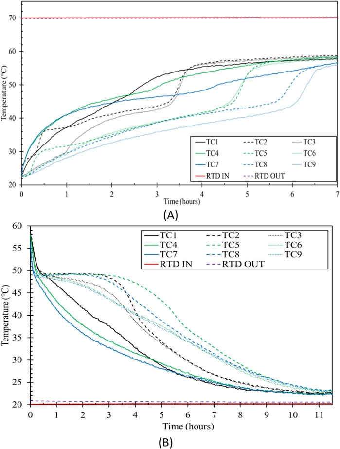
Figure 8. Four snowflake fin configuration PCM temperature distribution during (A) charging and (B) discharging.
3.3 Six-fin configurations
It has been demonstrated that increasing the number of fins while maintaining the geometry, the volume of fin material, and the length of fins speeds up processing (Shank et al., 2022). The data shown in Figure 4 indicate that using six-fins is superior to four-fins for charging and discharging for every configuration. Both charging and discharging durations are greatly reduced when the number of fins increases while the length stays constant, supporting earlier findings. The following sections provide a detailed discussion on the effect of increasing the number of fins to six for each configuration.
3.3.1 Six radial fins configuration
The case with six radial fins took 4.86 h for charging and 9.58 h for discharging, which are 89.76% and 76.87% less than the benchmark case, respectively. As seen in Figure 9, using six radial fins is more efficient for charging and discharging than four radial fins. This is because the extra fins provide a larger interfacial surface area and lower thermal resistance between the PCM and the HTF. The PCM temperature distribution during charging and discharging show the same trends as those observed in the four radial fin case, however the increase in the number of fins greatly reduces overall cycle time.
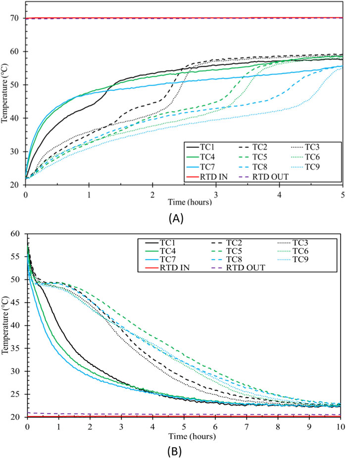
Figure 9. Six radial fin configuration PCM temperature distribution during (A) charging and (B) discharging.
3.3.2 Six Y-Fins configuration
The case assisted by six Y-fins takes 3.97 h to charge fully and 7.03 h to discharge. Compared to the benchmark, this represents a 91.63% and 83.03% reduction in charging and discharging, respectively. Figure 10 depicts the PCM temperature distribution during charging and discharging for the case with six Y-fins. The improvement is made to allow for deeper penetration of the fins into the container to increase the heat transfer rate through conduction that can take place in the early stages of the charging process. This helped in melting the PCM in a shorter time, because more PCM was in direct contact with the fins. The PCM temperature trends for charging, Figure 10A, and discharging, Figure 10B, are comparable to those of the case with four Y-fins, however, the processes take much less time to complete. The fins provided a more even temperature distribution and covered a larger surface area than the four-fin case, improving heat transfer efficiency from the HTF to the PCM.
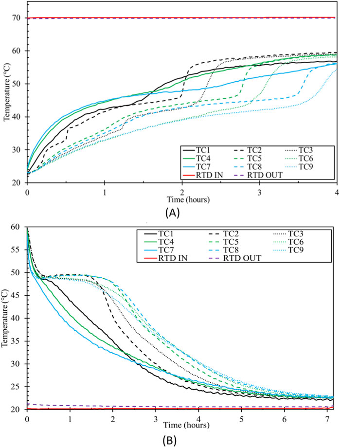
Figure 10. Six Y-fin configuration PCM temperature distribution during (A) charging and (B) discharging.
3.3.3 Six snowflake fins configuration
The configuration with six-snowflake fins requires 3.98 h to charge fully and 5.74 h to discharge fully. This represents a reduction in charging and discharging of 91.61% and 86.14%, respectively, over the benchmark case. The PCM temperature distributions for charging and discharging processes of this case are shown in Figure 11. The six-snowflake fin configuration has the greatest interfacial surface area among all tested cases, increasing the amount of heat that can be transferred in and out of the system, however, the total charging time for the six snowflake fins is almost identical to the six Y-fins. The additional fin branch in the snowflake configuration enhances conduction heat transfer during the early stages of melting. However, it obstructs the motion of the molten PCM in the later stages of charging, thereby suppressing natural convection. As a result, no significant improvement is observed compared to the Y-fin configuration during the melting process. In contrast, the impact is more pronounced during discharging, as solidification relies heavily on conduction, which is enhanced by the extra fin branch in the snowflake configuration. For discharging, the temperature distribution is comparable to the six Y-fin case, but the temperature changes happen at a slightly faster rate.
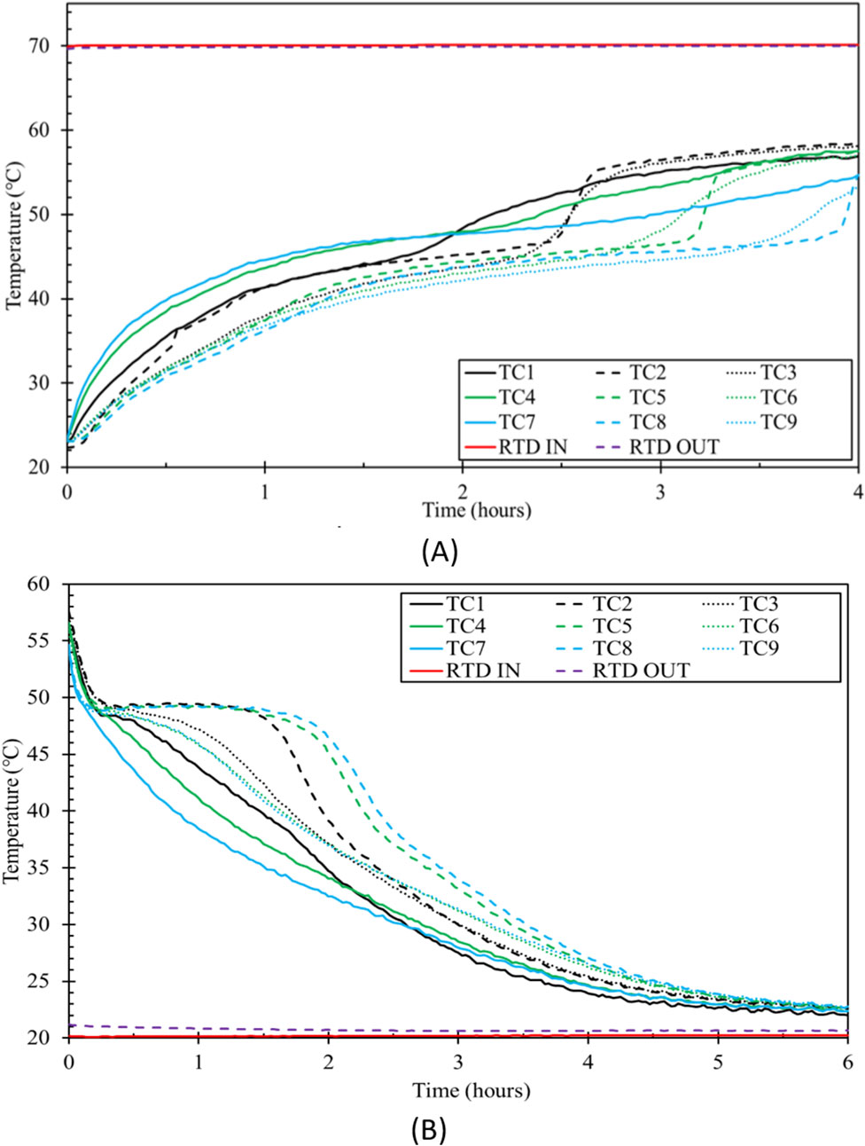
Figure 11. Six snowflake fin configuration PCM temperature distribution during (A) charging and (B) discharging.
The finned designs demonstrated excellent enhancement in charging and discharging performance compared to the benchmark case. In addition to enhancing heat transfer to all areas of the PCM container far from the central pipe, there is a definite trend toward shorter timeframes with increasing fins over the zero-fin benchmark case. The arrangement with six snowflake fins performed best when evaluating total time for the combined charging and discharging cycles.
The thermal performance observed in this study can be attributed to the interplay of three main mechanisms: conduction, natural convection, and phase change. Initially, during the charging process, conduction is the primary mode of heat transfer, with fins increasing the surface area available for heat transfer between HTF and the PCM. As the PCM begins to melt, natural convection takes over, driven by the density differences between the solid and liquid phases of the PCM. This convection enhances heat transfer within the PCM, accelerating the melting process and reducing the charging time. The phase change process itself, characterized by the absorption of latent heat, occurs within a relatively narrow temperature range, further contributing to the system’s thermal response.
3.4 System energy response
The energy response of the system is assessed as a verification method for examining charging and discharging. Equation 1 is used to determine the system thermal power
Figures 12–14 depict the system energy response during charging and discharging processes for the benchmark, four fin, and six fin configurations, respectively. The process of charging and discharging exhibits thermal energy storage or dissipation, as represented by the area under the curve. This phenomenon is relatively consistent across cases due to the constant volume of the PCM used in different cases. There is a variance in processing times between trials. More efficient cases demonstrate a more remarkable ability to receive or dissipate thermal energy in a shorter duration than other cases. Each test begins with a heat shock event that is a constant factor in all energy graphs. This event results in a substantial energy transfer between the HTF and the PCM during the initial minutes of the experiment, due to the significant temperature difference between the two components.
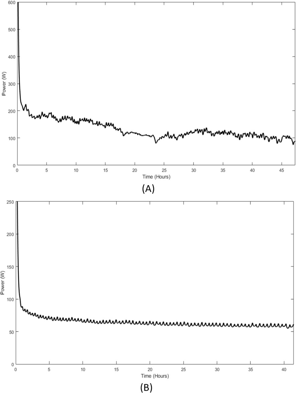
Figure 12. PCM energy response of benchmark case during (A) charging and (B) discharging.
The energy absorption during the charging tests for the four-fin case with three configurations is shown in Figure 13 (A). It is vital to note that this energy absorption does not represent the total energy stored in the PCM but rather the energy that the PCM has gradually absorbed from the HTF. As a result, the energy exchange also diminishes as the temperature differential between the PCM and the HTF narrows. Because Y-fins and Snowflake fins have similar interfacial surface areas, their initial thermal shock behaviors are also similar. As the test goes on, Y and Snowflake fins perform better. The difference in thermal shock in both scenarios is shown in Figures 13A,B. Radial and Y-fins in six-fins have a comparable thermal shock to snowflake-fin case, which experiences severe thermal shock. However, the thermal energy trends differently when charged in the four and six-fin cases. The energy absorbed following the thermal shock is higher in the branching fins than in the radial fins. Overall, the design of the six snowflake fins absorbed energy the fastest. The thermal power reported towards the end of the charging process does not fully account for the energy required to further charge the PCM. A portion of the thermal energy is lost to the surroundings due to heat transfer through convection and radiation. Despite the insulation around the PCM container, heat loss increases as the PCM near the container walls warms up. The temperature difference between the outer PCM layer and the room temperature environment grows, leading to higher heat loss. This explains the residual thermal power, which does not contribute to PCM melting or system charging but instead dissipates to the surroundings. Future studies could explore ways to minimize these losses, such as improving the insulation or enhancing the experimental setup.
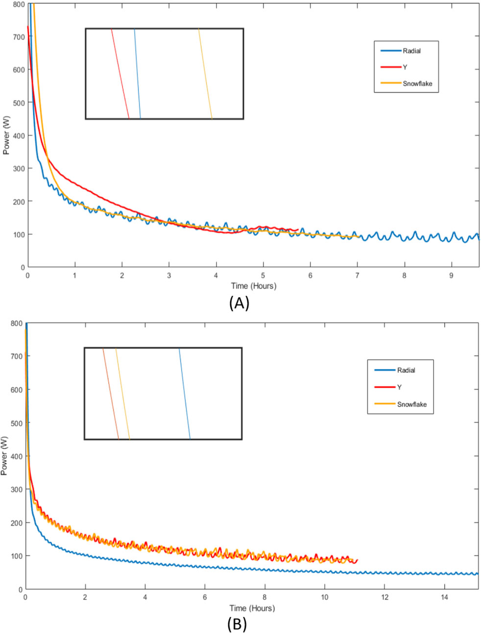
Figure 13. PCM energy response during charging with (A) four-fin and (B) six-fin cases.
(A) & (B) show how much energy is released throughout the discharging process from different configurations assisted by four and six fins. The discharging process takes approximately twice as long as the charging time for all the finned configurations. This is because solidification during discharging relies almost solely on conduction, whereas melting during charging is driven by both conduction and natural convection. These figures demonstrate that branching fin cases experience high thermal shock. The arrangement with six snowflake fins performs the best in both scenarios, with behavior identical to the charging operations. Snowflake and Y-fin performances, shown in Figures 14A,B, are comparable. In contrast, all fins in a six-fin design operate similarly, except for the initial thermal shock area.
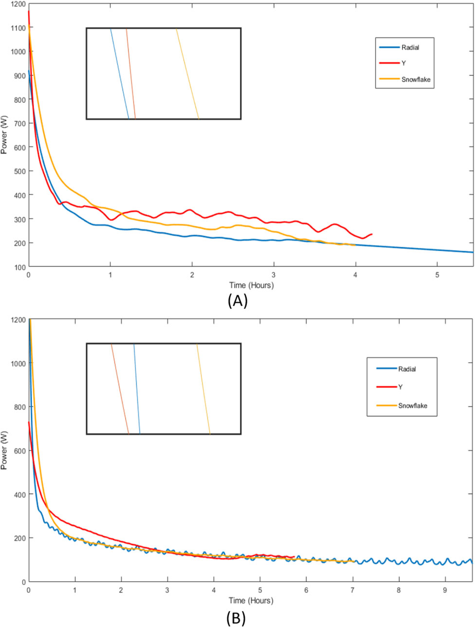
Figure 14. PCM energy response during discharging with (A) four-fins and (B) six-fins.
3.5 Effect of fin surface area on charging time
Figure 15 illustrates the effect of fin surface area on charging time for different fin configurations. As expected, increasing the fin surface area generally leads to a reduction in charging time. Among the configurations, the six-branch fin configurations (Y-fins and snowflake fins) exhibit significantly shorter charging times compared to the other fin configurations. This trend highlights the impact of increased surface area and the branched fin design, which enhances heat transfer rate within the system. For both fin quantities, increasing the surface area from the radial configuration to the Y configuration results in a significant reduction in charging time. The figure also suggests that after a certain point, further increases in surface area (Y to snowflake) do not continue to yield a significant reduction in charging time, indicating that there is an optimal fin surface area for a given amount of fin material (copper). Beyond this optimal point, additional surface area has diminishing returns in improving charging efficiency, suggesting a balance between fin surface area and material usage for maximum performance.
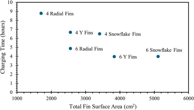
Figure 15. Charging time versus total fin surface area for all fin configurations.
3.6 Comparison with previous studies
To provide a more comprehensive understanding of the thermal performance of LHTES systems enhanced by fins, this study is compared with the previous works of the authors (Tiari and Hockins, 2021; Tiari et al., 2022; Shank et al., 2023). These studies investigated various fin configurations, including radial, annular, and variable-length fins, and their effects on the charging and discharging processes of LHTES systems. Although the PCM, the container and central pipe geometry, and operating conditions were similar across all these studies, it should be noted that the amount of fin material (copper) used in each case varied slightly. This minor difference in the volume of copper could have a small effect on the accuracy of the comparisons, as the thermal performance is also influenced by the fin material volume. Despite these variations, the trends observed in the current study are in line with the findings from the previous works, highlighting the effectiveness of branched fins in improving thermal performance.
In Tiari and Hockins (2021), the study focused on the use of annular and radial fins to enhance heat transfer in a LHTES system with RT-55 PCM. The results revealed that the eight radial fins configuration was the most effective, reducing the charging time by 86.6% and the discharging time by 80.1% compared to the benchmark. These results are similar to the findings observed in the current study, where branched fins also led to significant reductions in charging and discharging times. For instance, the six-fin configurations with Y-fins and snowflake fins reduced the charging times by 91.63% and 91.61%, and the discharging times by 83.03% and 86.14%, respectively.
In Tiari et al. (2022), the study utilized annular fins of variable diameter to enhance heat transfer within the LHTES system. The results showed that configurations with increasing fin diameter from top to bottom reduced charging times by up to 89.45% and discharging times by 77.41% for the twenty-annular fin cases compared to the benchmark. These results are in close agreement with the current study’s findings using branched fins, where six Y-fins and six snowflake fins configurations reduced charging and discharging times by 91.63% and 83.03%, and 91.61% and 86.14%, respectively. The current study builds on these earlier findings by incorporating branched fin geometries, which improve heat transfer by promoting natural convection within the PCM. While the annular fins in Tiari et al. (2022) provided substantial improvement in thermal performance, the branched fins in the current study show even greater potential, particularly in promoting convection and increasing heat penetration throughout the PCM.
In Shank et al. (2023), a comparison was made between variable-length and uniform-length radial fins, with variable-length fins extending further into PCM. This study found that the configuration with four variable-length fins, extending the furthest into the PCM, resulted in the greatest reduction in both charging (79.34%) and discharging times (49.53%) compared to the benchmark. All the fin configurations tested in the current study outperformed the uniform and variable-length radial fins tested in Shank et al. (2023). The branched fins in the current study, similar to variable-length and uniform radial fins, enhance heat penetration and improve natural convection, leading to faster phase change and more efficient thermal performance.
The findings of the current study are consistent with and expand upon the results from previous works by the authors. The use of branched fins offers significant advantages in thermal performance, particularly by enhancing natural convection within the PCM during charging. This study also contributes to the literature by providing a direct experimental comparison of branched fins, which were not explored in previous works, and shows their potential for further enhancing the thermal performance of LHTES systems. The results underscore the importance of increasing the surface area and facilitating natural convection within PCM to optimize heat transfer rates. In conclusion, this work not only confirms the findings from earlier studies but also introduces a new perspective on the use of branched fins for improving the performance of LHTES systems, providing a basis for future studies to explore these configurations in more detail and apply them to larger-scale systems.
4 Conclusion
This study presents a novel experimental evaluation of the performance of LHTES systems enhanced by branched fins. Unlike previous work that primarily relied on numerical simulations, this research provides critical experimental validation of the effectiveness of branched fin configurations including radial, Y-shaped, and snowflake fins in improving thermal performance. In the current work, the charging and discharging capabilities of an LHTES system are improved, with two cases of branching fins being assessed. Compared to the zero-fin benchmark configuration, introducing fins improved the thermal performance of the PCM resulted in reduced charging and discharging times of the LHTES system. The first case branched fins reduced charging time by 81.52%, 85.97%, and 86.30% for four radial fins, four Y-fins, and four snowflake fins, respectively, compared to the benchmark. Discharging times were reduced by 63.45% for four radial fins, 73.64% for four Y-fins, and 73.20% for four snowflake fins. The charging times for the six radial fins, six snowflake fins, and six Y-fins were reduced by 89.76%, 91.61%, and 91.63%, respectively. The discharging time was reduced for six radial fins, six Y-fins, and six snowflake fins, by 76.87%, 83.03%, and 86.14%, respectively. An energy response from the system was used to validate the charging and discharging timeframes. The analysis led to the following findings:
• In comparison to the benchmark, the system improvement incorporating branched fins reduces charging and discharging times substantially. Including branched fins allows for more heat penetration into every area of the PCM inside the container. This speeds up the melting of the PCM and, in turn, the onset of initial conduction and subsequent natural convection, reducing the charging time. Although the liquid fraction of the PCM was not directly measured in this study, the temperature profiles indicate that the PCM underwent complete melting during the charging phase. The higher temperatures at the top of the container suggest that molten PCM rises due to buoyancy, indicating all the PCM reached the liquid phase. This aligns with the observed accelerated heat transfer, as natural convection enhances the melting process by increasing the rate at which heat is distributed throughout the PCM.
• This study found that using branched fins in the LTHES system resulted in a shorter processing time. Additionally, the increased heat transfer area between the PCM and the HTF with the same amount of copper in the fins led to a more significant decrease in the charging and discharging times.
• Among the four and six-fin arrangements, six Y-fins and six snowflake fins configurations had the shortest charging time. This was caused by six-fin configurations having more surface area and a longer distance from the HTF pipe. Natural convection quickly became the dominant mode of heat transfer in all configurations due to the speed at which the PCM melted around the fins.
• Six snowflake fins were the most efficient fin arrangement for reducing combined charging and discharging periods. Compared to the four-fin configuration, the configuration with six snowflake fins reduced the discharging time since it had the most extended maximum fin length away from the HTF pipe. This demonstrates that thermal penetration is more significant than the fin count in discharging.
This study provides a comprehensive experimental evaluation of the performance of LHTES systems enhanced with branched fins, showing a significant reduction in both charging and discharging times. The results not only emphasize the novelty of branched fin configurations but also their practical applications. These enhanced systems can improve the efficiency of energy storage, particularly in renewable energy systems where efficient storage and timely release of energy are crucial. Branched fins, by promoting natural convection and improving heat transfer, can be implemented in large-scale energy storage solutions such as solar thermal power plants and industrial heat recovery systems.
While this study provides a comprehensive experimental analysis of branched fins in LHTES systems, several avenues remain for future research. Optimization and cost analysis of the fin designs for large-scale systems is an important next step, as the configurations explored in this study were limited to laboratory-scale systems. Future studies could also investigate the combined use of branched fins and other passive heat transfer enhancement techniques, such as highly conductive nanoparticle dispersion, to further enhance performance. Additionally, it would be valuable to explore the long-term stability, thermal cycling fatigue, corrosion, and PCM degradation and durability of these fin-enhanced systems in real-world conditions, including their application in thermal energy storage for solar power plants or industrial waste heat recovery systems.
Data availability statement
The original contributions presented in the study are included in the article/supplementary material, further inquiries can be directed to the corresponding author.
Author contributions
SP: Investigation, Data curation, Software, Validation, Visualization, Writing – original draft. JM: Data curation, Writing – original draft, Formal Analysis. KF: Formal Analysis, Writing – review and editing. ST: Formal Analysis, Writing – review and editing, Conceptualization, Funding acquisition, Methodology, Project administration, Resources, Supervision.
Funding
The author(s) declare that no financial support was received for the research and/or publication of this article.
Acknowledgments
The authors would like to express gratitude to Gannon University for supporting this project.
Conflict of interest
The authors declare that the research was conducted in the absence of any commercial or financial relationships that could be construed as a potential conflict of interest.
The author(s) declared that they were an editorial board member of Frontiers, at the time of submission. This had no impact on the peer review process and the final decision.
Generative AI statement
The authors declare that no Generative AI was used in the creation of this manuscript.
Publisher’s note
All claims expressed in this article are solely those of the authors and do not necessarily represent those of their affiliated organizations, or those of the publisher, the editors and the reviewers. Any product that may be evaluated in this article, or claim that may be made by its manufacturer, is not guaranteed or endorsed by the publisher.
References
Al-Shuwaili, H., Kakhki, M. S., Al-Aridhee, S., Ghorbani, A., Entezari, S., and Sardarabadi, M. (2023). Performance enhancement of triplex-tube heat storage unit using branched fins during solidification and melting processes: a 2D numerical parametric investigation. Therm. Sci. Eng. Prog. 38, 101653. doi:10.1016/j.tsep.2023.101653
Anova Cullinary (2024). Anova precision cooker. Available online at: https://anovaculinary.com/products/anova-precision-cooker.
Ao, C., Yan, S., Zhao, L., and Wu, Y. (2023). Assessment on the effect of longitudinal fins upon melting process in a latent heat thermal energy storage unit. J. Energy Storage 59, 106408. doi:10.1016/j.est.2022.106408
Blue-White Industries (2023). F-1000. Available online at: https://www.blue-white.com/product/f-1000-digital-paddlewheel-flow-meter/.
Cabeza, L. F. (2022b). “Introduction to the section on thermodynamics of energy storage,” in Encyclopedia of energy storage. Editor L. F. Cabeza (Amsterdam, Netherlands: Elsevier), 1–4. doi:10.1016/B978-0-12-819723-3.00157-8
Grundfos (2024). UPS 15. Available online at: https://product-selection.grundfos.com/us/products/up-ups-series-100-north-america/ups-15-north-america?tab=models.
Hydrobuilder (2024). Active aqua water chillers with power boost. Available online at: https://hydrobuilder.com/active-aqua-chiller-with-power-boost.html?opts=eyJhdHRyaWJ1dGU5MTMiOiI2NjcwIn0=.
Hydrofarm (2024). Active aqua submersible water pump. Available online at: https://www.hydrofarm.com/p/active-aqua-submersible-water-pump/aapw250.
Kiwan, S., and Al-Nimr, M. A. (2001). Using porous fins for heat transfer enhancement. J. Heat. Transf. 123, 790–795. doi:10.1115/1.1371922
Kumar, C. M. S., Singh, S., Gupta, M. K., Nimdeo, Y. M., Raushan, R., Deorankar, A. V., et al. (2023). Solar energy: a promising renewable source for meeting energy demand in Indian agriculture applications. Sustain. Energy Technol. Assess. 55, 102905. doi:10.1016/j.seta.2022.102905
Luo, M., Zhang, Y., Niu, Y., Lu, B., Wang, Z., Zhang, J., et al. (2023). Experimental and numerical investigations on the thermal performance enhancement of a latent heat thermal energy storage unit with several novel snowflake fins. Renew. Energy 217, 119158. doi:10.1016/j.renene.2023.119158
Maghrabie, H. M., Olabi, A. G., Alami, A. H., Radi, M. A., Zwayyed, F., salamah, T., et al. (2022). Numerical simulation of heat pipes in different applications. Int. J. Thermofluids 16, 100199. doi:10.1016/j.ijft.2022.100199
McMaster-Carr (2024a). Copper. Available online at: https://www.mcmaster.com/products/copper/.
McMaster-Carr (2024b). Flexible rubber foam pipe insulation sheet. Available online at: https://www.mcmaster.com/9349K5/.
McMaster-Carr (2024c). Plastics. Available online at: https://www.mcmaster.com/products/acrylic/.
Mobedi, M., Hooman, K., and Tao, W.-Q. (2022). Solid/liquid thermal energy storage: modeling and applications. First Edn. (Boca Raton, FL: CRC Press). doi:10.1201/9781003213260
Moffat, R. J. (1988). Describing the uncertainties in experimental results. Exp. Therm. Fluid Sci. 1 (1), 3–17. doi:10.1016/0894-1777(88)90043-X
Narkhede, S., Sur, A., Kothari, G., and Netke, A. (2024). Design and thermal analysis of Fin-PCM-integrated thermal management system for lithium-ion cylindrical battery pack. Proc. Inst. Mech. Eng. Part E. doi:10.1177/09544089231221668
National Instruments (2023a). CompactDAQ product bundles. Available online at: https://www.ni.com/en/shop/compactdaq/compactdaq-measurement-bundles.html?cid=Paid_Search-7013q000001rC7sAAE-Consideration-GoogleSearch_150020924390&utm_keyword=cdaq&gclid=CjwKCAjwzuqgBhAcEiwAdj5dRvu8taBEKcx1Vl2J4m2tTsWmPxndmvwuRF0QHQShR1LCLoRG7-lqdRoC39oQAvD_BwE.
National Instruments (2023b). What is NI LabVIEW? Graphical programming for test and measurement. Available online at: https://www.ni.com/en/shop/labview.html?cid=Paid_Search-7013q000001rC7oAAE-Consideration-GoogleSearch_102713974073&utm_keyword=labview+software&s_kwcid=AL%216304%213%21449107487676%21e%21%21g%21%21labview+software&gclid=CjwKCAjwzuqgBhAcEiwAdj5dRlEFPrD9iruB4FsdPuwQXjFCVoDYZeAvQt27ptvQhzuwmdAz32hR6RoCw78QAvD_BwE.
Niksiar, P., Rogillio, C., Torab, H., and Tiari, S. (2024). Experimental study of a silica sand sensible heat storage system enhanced by fins. Energies 17 (21), 5402. doi:10.3390/en17215402
Omega (2024a). Thermocouple probes with PFA insulated lead wire. Available online at: https://www.omega.com/en-us/temperature-measurement/temperature-probes/probes-with-lead-wires/tj36-icin/p/TJ36-CASS-18G-6-BX.
Omega (2024b). RTD probe with insulated wire and shrink-tube support. Available online at: https://www.omega.com/en-us/temperature-measurement/temperature-probes/probes-with-lead-wires/pr-10/p/PR-10E-3-100-1-4-4.
Ren, F., Du, J., Yang, X., and Huang, X. (2023). Optimization on a novel irregular snowflake fin for thermal energy storage using response surface method. Int. J. Heat. Mass Transf. 200, 123521. doi:10.1016/j.ijheatmasstransfer.2022.123521
Rubitherm (2024). PCM RT-LINE. Available online at: https://www.rubitherm.eu/en/index.php/productcategory/organische-pcm-rt.
Shank, K., Bernat, J., Justice, Q., Niksiar, P., and Tiari, S. (2023). Experimental study of a latent heat thermal energy storage system assisted by variable-length radial fins. J. Energy Storage 68, 107692. doi:10.1016/j.est.2023.107692
Shank, K., Bernat, J., Regal, E., Leise, J., Ji, X., and Tiari, S. (2022). Experimental study of varying heat transfer fluid parameters within a latent heat thermal energy storage system enhanced by fins. Sustainability 14, 8920. doi:10.3390/su14148920
Sharifi, N., Bergman, T. L., and Faghri, A. (2011). Enhancement of PCM melting in enclosures with horizontally-finned internal surfaces. Int. J. Heat. Mass Transf. 54, 4182–4192. doi:10.1016/j.ijheatmasstransfer.2011.05.027
Sheikholeslami, M., Lohrasbi, S., and Ganji, D. D. (2016). Numerical analysis of discharging process acceleration in LHTESS by immersing innovative fin configuration using finite element method. Appl. Therm. Eng. 107, 154–166. doi:10.1016/j.applthermaleng.2016.06.158
Siddik, A. B., Khan, S., Khan, U., Yong, L., and Murshed, M. (2023). The role of renewable energy finance in achieving low-carbon growth: contextual evidence from leading renewable energy-investing countries. Energy 270, 126864. doi:10.1016/j.energy.2023.126864
Teggar, M., Ajarostaghi, S. S. M., Yıldız, Ç., Arıcı, M., Ismail, K. A. R., Niyas, H., et al. (2021). Performance enhancement of latent heat storage systems by using extended surfaces and porous materials: a state-of-the-art review. J. Energy Storage 44, 103340. doi:10.1016/j.est.2021.103340
Tiari, S., and Hockins, A. (2021). An experimental study on the effect of annular and radial fins on thermal performance of a latent heat thermal energy storage unit. J. Energy Storage 44, 103541. doi:10.1016/j.est.2021.103541
Tiari, S., Hockins, A., and Mahdavi, M. (2021). Numerical study of a latent heat thermal energy storage system enhanced by varying fin configurations. Case Stud. Therm. Eng. 25, 100999. doi:10.1016/j.csite.2021.100999
Tiari, S., Hockins, A., and Shank, K. (2022). Experimental study of a latent heat thermal energy storage system assisted by varying annular fins. J. Energy Storage 55, 105603. doi:10.1016/j.est.2022.105603
Tiari, S., Qiu, S., and Mahdavi, M. (2015). Numerical study of finned heat pipe-assisted thermal energy storage system with high temperature phase change material. Energy Convers. Manag. 89, 833–842. doi:10.1016/j.enconman.2014.10.053
Tiari, S., Qiu, S., and Mahdavi, M. (2016). Discharging process of a finned heat pipe–assisted thermal energy storage system with high temperature phase change material. Energy Convers. Manag. 118, 426–437. doi:10.1016/j.enconman.2016.04.025
Tofani, K., and Tiari, S. (2021). Nano-enhanced phase change materials in latent heat thermal energy storage systems: a review. Energies 14, 3821. doi:10.3390/en14133821
U.S. Energy Information Administration (2023). Annual energy Outlook 2023. Available online at: https://www.eia.gov/outlooks/aeo/.
Vijjapu, R., and Tiwari, S. (2022). “Thermodynamics of sensible thermal energy storage systems,” in Encyclopedia of energy storage. Editor L. F. Cabeza (Amsterdam, Netherlands: Elsevier), 171–185. doi:10.1016/B978-0-12-819723-3.00149-9
Yu, D., Qiu, Y., Zhang, X., and Liu, F. (2022). Research on the energy discharging performance of Y-shaped fin. J. Energy Storage 50, 104704. doi:10.1016/j.est.2022.104704
Zamengo, M., Ryu, J., and Kato, Y. (2015). Chemical heat storage of thermal energy from a nuclear reactor by using a magnesium hydroxide/expanded graphite composite material. Energy Procedia 71, 293–305. doi:10.1016/j.egypro.2014.11.882
Zhang, C., Li, J., and Chen, Y. (2020). Improving the energy discharging performance of a latent heat storage (LHS) unit using fractal-tree-shaped fins. Appl. Energy 259, 114102. doi:10.1016/j.apenergy.2019.114102
Zhang, J., Cao, Z., Huang, S., Huang, X., Liang, K., Yang, Y., et al. (2022). Improving the melting performance of phase change materials using novel fins and nanoparticles in tubular energy storage systems. Appl. Energy 322, 119416. doi:10.1016/j.apenergy.2022.119416
Zhang, S., and Wang, Z. (2018). Thermodynamics behavior of phase change latent heat materials in micro-/nanoconfined spaces for thermal storage and applications. Renew. Sustain. Energy Rev. 82, 2319–2331. doi:10.1016/j.rser.2017.08.080
Zycher, B. (2019). The trouble with “renewable” energy. Available online at: https://www.aei.org/articles/the-trouble-with-renewable-energy/.
Keywords: latent heat thermal energy storage, branched fins, radial fins, y fins, snowflake fins, shell and tube heat exchanger, experimental testing, phase change material
Citation: Pandiri S, Murphy J, Fouladi K and Tiari S (2025) Experimental analysis of a latent heat thermal energy storage unit enhanced by branched fins. Front. Therm. Eng. 5:1561295. doi: 10.3389/fther.2025.1561295
Received: 15 January 2025; Accepted: 14 May 2025;
Published: 23 May 2025.
Edited by:
Vincenza Brancato, National Research Council (CNR), ItalyReviewed by:
Anirban Sur, Symbiosis International University, IndiaEngin Gedik, Karabük University, Türkiye
Elias Papanicolaou, National Centre of Scientific Research Demokritos, Greece
Copyright © 2025 Pandiri, Murphy, Fouladi and Tiari. This is an open-access article distributed under the terms of the Creative Commons Attribution License (CC BY). The use, distribution or reproduction in other forums is permitted, provided the original author(s) and the copyright owner(s) are credited and that the original publication in this journal is cited, in accordance with accepted academic practice. No use, distribution or reproduction is permitted which does not comply with these terms.
*Correspondence: Saeed Tiari, c3RpYXJpQHdpZGVuZXIuZWR1