 Satwinder Singh
 Ravinder Kumar
- 1Department of RISE, Chandigarh Engineering College, Mohali, India
- 2Department of Mechanical Engineering, Guru Nanak Dev University, Amritsar, India
Introduction: Desiccant-based dehumidification is a promising energy-efficient solution for air moisture control, particularly in humid climates.
Methods: This paper aims to experimentally evaluate the performance of a counter flow packed bed dehumidifier using PVC honeycomb packing with calcium chloride solution as a desiccant. Desiccant solution flow rate, air mass flow rate, and air inlet temperature were the main input variables taken into account in the experiment.
Results: The performance of the system was assessed by measuring the moisture removal rate, the exit air temperature, and the air’s outlet humidity ratio. Results show that increasing the air mass flow rate from 0.00074 to 0.00119 kg/s and raising the desiccant inlet temperature from 50 °C to 70 °C increases the moisture extraction rate from 0.032 × 10⁻⁴ kg/s to 0.225 × 10⁻⁴ kg/s and a corresponding rise in outlet humidity ratio.
Discussion: These outcomes contribute to the optimization of liquid desiccant dehumidifiers and hence support their broader application in energy-efficient climate control systems.
1 Introduction
The dehumidification of air is necessary in the modern world due to the rising trend in humidity in order to create comfortable and healthy indoor environments for many industrial and agricultural operations. Rapid population growth and a higher standard of living are responsible for the significant increase in space cooling demand. This demand is expected to increase by 50% between 2010 and 2040 (Pérez-Lombard et al., 2008). The dehumidification process eliminates both sensible and latent heat loads. Vapor compression refrigeration systems are one of the best-known methods and are utilized in practically every home and business setting. Such a method uses refrigerants to cool and dehumidify the air, but their use causes the ozone layer to continuously weaken. In addition, this kind of traditional method involves cooling below the dew-point temperature and reheating to the required indoor temperature. Because of the excessive cooling and subsequent reheating needed to reach the desired supply air temperature, this sequence results in a significant energy loss. Desiccant dehumidification, therefore, emerges as a promising alternative that eliminates the use of harmful refrigerants and compressors while favoring air dehumidification. Desiccant dehumidification, therefore, represents a substitute that favors air dehumidification. The desiccant dehumidification approach employs a substance called a “desiccant” that retains moisture because of the difference in vapor pressure that exists between the desiccant and the moisture in the air. Desiccant temperature and concentration have an impact on desiccant vapor pressure in liquid desiccant dehumidification (Jain and Bansal, 2007). Its high moisture absorption capacity is the result of a desiccant solution with a higher concentration and a lower temperature. By forcing the intake stream of air past the desiccant material, desiccant cooling dehumidifies the air and lowers it to the proper indoor temperature. Water vapor that has been adsorbed or absorbed must be released from the desiccant for the system to continue operating, allowing it to sufficiently dry to capture water vapor.
Sensible coolers, such as heat exchangers, cooling coils, and evaporative coolers, reduce the sensible load of dehydrated air to appropriate, convenient conditions after the latent heat load, or moisture from the processed air, is expelled with the aid of the desiccant material in the dehumidifier. The development of desiccant materials has become essential to the expansion of desiccant air conditioning. The characteristics of desiccant material have a big impact on how well desiccant air conditioners work. There are two different kinds of desiccant materials: solid and liquid. Both have industrial uses requiring a lower dew point. A desiccant’s strength is determined by its surface vapor pressure, which increases exponentially with desiccant temperature. Above the surface of the desiccant solution, the desiccant produces an area of low vapor pressure. This causes the desiccant to release heat, which warms the air and causes it to become dry and dehumidified. Desiccants eliminate moisture from the air in two ways: adsorption and absorption. Liquid desiccants, such as LiCl, CaCl2, and LiBr, are included in the list of absorbents (ANSI, 2005). One of the most essential elements of this dehumidification technology is the dehumidifier that comes with the packing materials. The contacting surface where the air and desiccant solution interact inside the dehumidifier is provided by the packing materials.
As shown in Figure 1, the desiccant solution weakens and exits the dehumidifier after absorbing the moisture from the ambient intake air.
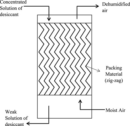
Figure 1. Liquid desiccant dehumidification mechanism.
2 Literature review
Kalpana and Subudhi (2022) comprehensively reviewed the principles, types, and performance of liquid desiccant cooling systems integrated with evaporative coolers and found that liquid desiccant cooling systems with evaporative coolers offer a cost-effective and environmentally sustainable alternative to vapor compression systems, with notable energy savings. El-samahy et al. (2020) performed an experiment on the performance of packed tower regeneration with CaCl2 liquid desiccant and concluded that increasing air inlet temperature, air flow rate, and outlet solution temperature enhances the moisture extraction rate. Chen et al. (2020) presented research on liquid desiccant dehumidification and air conditioning systems, summarizing their physical features, types of dehumidifiers, and integration with other systems. They compared combinations with solar collectors, vapor compression systems, and heat pumps. Sonowal et al. (2023) investigated the impact of packing material and density on dehumidifier performance using coupled heat and mass transfer analysis and a parametric study using a less corrosive KCOOH solution. They concluded that effectiveness varies nonlinearly with packing density, with higher packing density resulting in higher condensation rates and decreased air pressure drop. Dong et al. (2017) studied the performance of liquid desiccant dehumidification using three packing types: corrugated structured, S-shaped polyvinyl chloride, and globular-shaped polypropylene, finding that performance improved with an increased desiccant/air mass flow rate ratio and inlet air temperature. He et al. (2025) tested a double-layer multi-stage desiccant packed bed and demonstrated that its performance was superior to that of other similar devices; this was primarily influenced by air humidity and material layer thickness. Fahad et al. (2025) evaluated the dehumidification performance of different salt solutions (LiCl, CdCl2, and NaCl) in liquid desiccant dehumidifiers using various concentrations, flow rates, and packed bed types to conclude that lithium chloride with a cellulose-packed bed achieved the highest dehumidification efficiency (88.3%), while CdCl2 and NaCl provided lower but more cost-effective alternatives. Bhowmik et al. (2022) explored the potential of a desiccant and VC integrated system, revealing that the system’s COP improves by 74.8% compared to a standalone VC system. Zhang et al. (2023) analyzed the behavior of heat and mass transfer coefficients and thermal mass in liquid desiccant dehumidification, revealing that heat and mass transfer coefficients follow exponential evolutionary laws, resulting in a simplified, more accurate dynamic model with up to 50% improved prediction accuracy. Liu et al. (2007) applied Celdek structured packing, using LiBr as a desiccant, to examine the effects of incoming desiccant variables and air on regenerator performance. Cho et al. (2019) conducted a comparative study on the potential of both cross-flow counterflow liquid desiccant dehumidifiers using Celdek packing. The effectiveness of an air dehumidifier was experimentally assessed by Zurigat et al. (2004) using triethylene glycol as a desiccant and aluminum and wood packing materials in a structured manner. Xiong et al. (2010) used an exergy approach and found that the regeneration temperature and air and desiccant mass flux dominated the operation of a new two-stage calcium chloride liquid desiccant dehumidifying system. Bai et al. (2018) presented a mathematical model to simulate the operation of a cross-flow parallel plate liquid desiccant system. Seenivasan et al. (2018) observed the operation of a dehumidifier with and without an indirect evaporative cooler using calcium chloride as a desiccant, finding that a decrease in the rate of moisture expulsion causes the dehumidifier’s effectiveness to decline. Using a wetted wall column setup, Shanmuga Priya and TJPRC (2019) compared the analysis of potassium formate, a new desiccant, with that of calcium chloride and lithium chloride; potassium formate proved to be more cost-effective and to require lower flow rates to achieve lower relative humidity. Jradi and Riffat (2014) utilized potassium formate as a desiccant in a counterflow liquid desiccant system. Using a numerical model, they examined how the effectiveness of the dehumidifier varies in proportion to the temperature, relative humidity, and desiccant flow rate of the intake air while varying inversely with respect to the heat exchanger’s air velocity and air-channel height. Using calcium chloride as a desiccant, Bassuoni (2011) investigated the effects of air flow rates, solution temperature, concentration, and packing thickness on a dehumidifier’s performance. Kumar and Asati (2018) examined how different inlet variables affected the efficiency of a liquid desiccant dehumidifier packed with Celdek and calcium chloride desiccant. They found that effectiveness increased as the desiccant flow rate and inlet humidity ratio rose.
Despite extensive studies on liquid desiccant dehumidification systems, the majority of them have focused on individual parameters or specific packing types rather than the combined effects of variables such as air mass flow, desiccant solution temperature, and air inlet temperature. This study is not a comprehensive experimental investigation that graphically correlates the air outlet temperature, moisture expulsion rate, and outlet humidity ratio in a unified model. Instead, we experimentally analyzed a packed-bed liquid desiccant dehumidifier utilizing calcium chloride as a desiccant with PVC honeycomb packing, filling this research gap by performing a systematic experimental investigation into the cumulative impact of such factors on dehumidifier performance. This extensive approach provided novel insights and in-depth performance analyses to guide practical optimization and enhance the design of packed-bed liquid desiccant dehumidification systems.
3 Experimental setup
Figure 2 depicts the test rig used for the experimentation. It includes two solution tanks—one for making concentrated calcium chloride solution and the other for accumulating weak desiccant solution—and a dehumidifier packed with honeycomb-structured PVC packing material. For steady air flow, a 0.75 H P centrifugal air blower was utilized, with a regulator for the air blower’s speed. The desiccant solution was pumped using a monoblock pump with a 0.5 H P rating and an hourly flow rate of 1,300–1,800 L. A rotameter measured the strong desiccant’s flow rate. To obtain varying aqueous desiccant solution flow rates, a gate valve was positioned between the pump and the rotameter. A 50-mm-diameter orifice disk was installed in the air exit conduit to measure the air flow rate, and a U-tube manometer measured the pressure head across the orifice plate. Psychrometers are installed in the inlet and outlet air conduits to record the characteristics of the incoming and dehumidified air. The actual picture of experimental facility is shown in Figure 3.
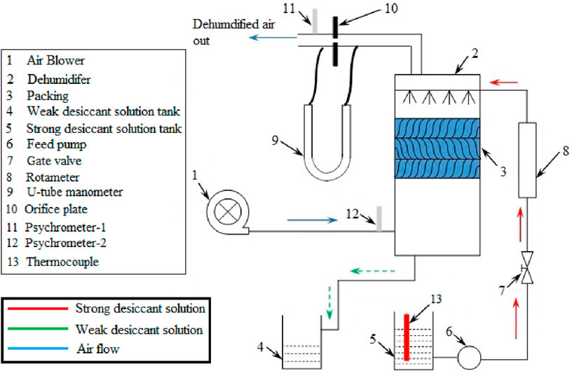
Figure 2. Experimental setup.
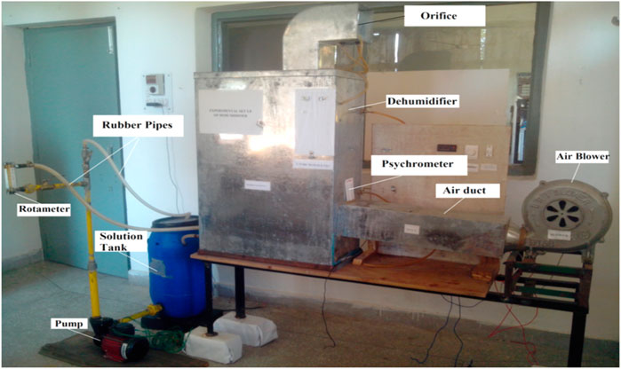
Figure 3. Photo of experimental facility.
3.1 Experimental procedure
The experiment began when the concentrated calcium chloride solution was placed in the solution tank, and the air blower and pump were turned on. To obtain the various air flow rates, the air blower’s speed was regulated. The rotameter recorded the varying solution flow rate values resulting from the gate valve opening and closing. Inside the dehumidifier, the air moved upward while the desiccant fell through the packing in a counter-flow style with the strong desiccant solution. The dehumidified air departed through the outlet air conduit. The U-tube manometer recorded the variation in pressure head as the air flowed through the orifice plate. Using a psychrometer installed in the air conduits, the dry and wet bulb temperatures of the approaching and dehumidified air were measured.
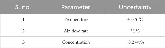
The domain of operating parameters is presented in Table 1.
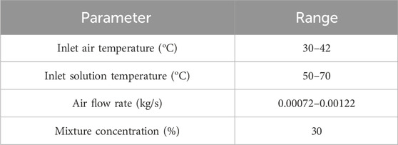
Table 1. Domain of operating parameters.
The data reduction used to calculate parameters such as the air flow rate and the moisture removal rate is given in Equations 1, 2.
4 Uncertainty analysis
To ensure the reliability of the reported results, an uncertainty analysis was performed for the key experimental measurements. The temperature measurements had an uncertainty of
5 Results and discussion
We conducted a number of experiments to determine how the air flow rate, solution flow rate, and inlet solution temperature of the inlet parameters affect the moisture removal rate, humidity ratio, and solution concentration of the outlet parameters.
5.1 Effect of air flow rate on the moisture removal rate
The graph in Figure 4 shows the variation of the moisture removal rate (
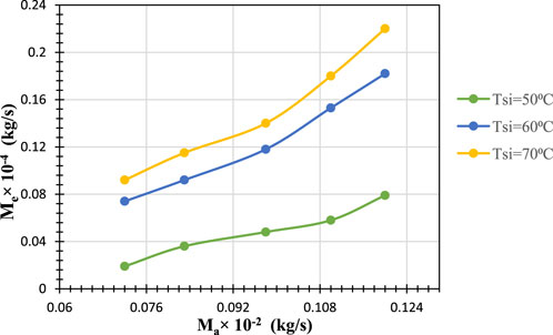
Figure 4. Effect of air flow rate on the moisture removal rate as a function of the solution inlet temperature.
5.2 Effect of air flow rate on outlet humidity ratio
For different solution temperatures at the inlet, Figure 5 illustrates how the outlet humidity ratio changes with the air flow rate. The outlet humidity ratio gradually increases with the air mass flow rate, and this increase becomes more significant at higher desiccant temperatures. For example, as the desiccant temperature rises from 60 °C to 70 °C, the humidity ratio at the outlet changes from 0.005 to 0.006 kg/kg of air, while at the lower desiccant temperature of 50 °C, the change is 0.003 kg/kg of air. This indicates that, as the air flow rate increases, the outlet humidity ratio changes more quickly at higher desiccant temperatures. This is because the mass transfer rate increases due to the higher temperature difference.
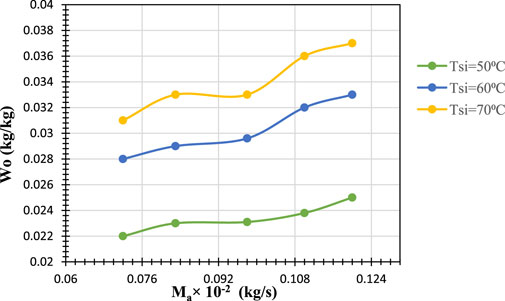
Figure 5. Effect of air flow rate on the outlet humidity ratio as a function of the solution inlet temperature.
5.3 Effect of the air flow rate on outlet air temperature
The graph in Figure 6 depicts the air outlet temperature varying slightly with the air mass flow rate at a solution temperature of 50 °C. The air outlet temperature does, however, rise somewhat when the solution temperature is between 60– and 70 °C, indicating that higher air flow rates result in greater heat transfer from the desiccant to the air. This is because the desiccant has more thermal energy at 60–70 °C than at 50 °C. The greater temperature differential between the desiccant and the incoming air encourages more heat transfer from the desiccant to the air. Moreover, the air transfers its latent heat to the desiccant solution, which causes the temperature of the air outlet to rise; this effect is more pronounced at higher temperatures because the desiccant absorbs moisture more rapidly.
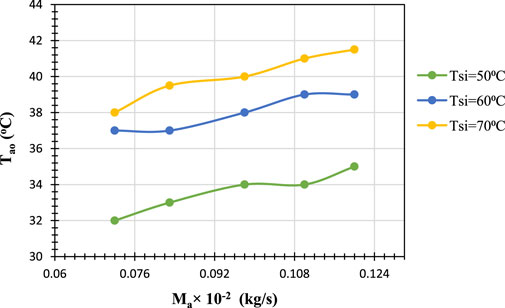
Figure 6. Effect of air flow rate on the outlet air temperature as a function of the solution inlet temperature.
5.4 Effect of inlet air temperature on moisture removal rate
The graph in Figure 7 shows the variation of the moisture removal rate with air inlet temperature for three different desiccant solution inlet temperatures. It is evident that for all
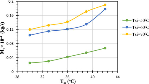
Figure 7. Effect of inlet air temperature on the moisture removal rate as a function of solution inlet temperature.
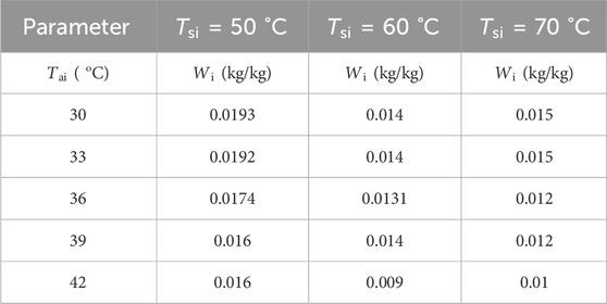
Table 2. Values of the inlet air’s specific humidity for different inlet air and desiccant inlet temperatures.
Thus, the graph clearly demonstrates that both higher air inlet and desiccant solution temperatures contribute to increased moisture removal rates, with the effect being significantly amplified at higher desiccant temperatures.
5.5 Effect of inlet air temperature on humidity ratio difference
Figure 8 shows the graph for the variation of the humidity ratio difference with air inlet temperature for three different desiccant solution inlet temperatures. For all three
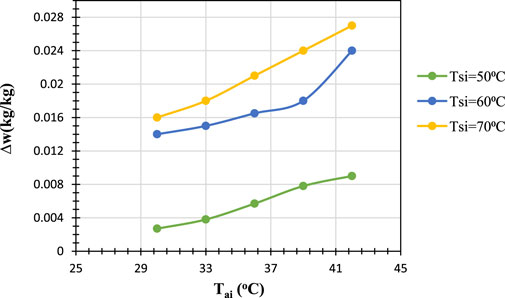
Figure 8. Effect of inlet air temperature on the humidity ratio difference as a function of solution inlet temperature.
6 Conclusion
We conducted an experimental investigation of a counterflow packed bed dehumidifier using a concentrated calcium chloride solution and reached the following conclusions.
i. The moisture extraction rate increased with both the air mass flow rate and the desiccant solution inlet temperature because of enhanced convective interaction and a larger vapor pressure difference between the air and the desiccant solution, raising the driving force for mass transfer.
ii. Higher desiccant temperatures cause a greater change in the humidity ratio with increasing air flow rate, indicating enhanced mass transfer due to larger temperature differences.
iii. The air outlet temperature increases slightly with the air mass flow rate, especially at higher desiccant solution temperatures. This rise is because of a greater temperature differential, in addition to moisture absorption at higher desiccant temperatures, resulting in improved heat transfer from the warmer desiccant to the air.
iv. The moisture removal rate increases with both higher air inlet and desiccant temperatures, leading to more pronounced elevated desiccant temperatures due to enhanced mass transfer.
v. The difference in humidity rises with the temperatures of the desiccant and the air inlet, suggesting improved dehumidification and increased moisture absorption at higher temperatures.
Data availability statement
The raw data supporting the conclusions of this article will be made available by the authors without undue reservation.
Author contributions
SS: Writing – original draft, Writing – review and editing, Conceptualization, Investigation. RK: Writing – review and editing, Supervision, Writing – original draft.
Funding
The author(s) declare that no financial support was received for the research and/or publication of this article.
Conflict of interest
The authors declare that the research was conducted in the absence of any commercial or financial relationships that could be construed as a potential conflict of interest.
Generative AI statement
The author(s) declare that no Generative AI was used in the creation of this manuscript.
Any alternative text (alt text) provided alongside figures in this article has been generated by Frontiers with the support of artificial intelligence and reasonable efforts have been made to ensure accuracy, including review by the authors wherever possible. If you identify any issues, please contact us.
Publisher’s note
All claims expressed in this article are solely those of the authors and do not necessarily represent those of their affiliated organizations, or those of the publisher, the editors and the reviewers. Any product that may be evaluated in this article, or claim that may be made by its manufacturer, is not guaranteed or endorsed by the publisher.
Abbreviations
References
Aristov, Yu.I., Glaznev, I. S., Freni, A., and Restuccia, G. (2006). Kinetics of water sorption on a CaCl2-in-silica-gel-pores sorbent: the effects of the pellet size and temperature. Kinet. Catal. 47, 770–775. doi:10.1134/S002315840605017X
Bai, H., Zhu, J., Chen, Z., and Chu, J. (2018). Parametric analysis of a cross-flow membrane-based parallel-plate liquid desiccant dehumidification system: numerical and experimental data. Energy Build. 158, 494–508. doi:10.1016/j.enbuild.2017.10.018
Bassuoni, M. M. (2011). An experimental study of structured packing dehumidifier/regenerator operating with liquid desiccant. Energy 36, 2628–2638. doi:10.1016/j.energy.2011.02.004
Bhowmik, M., Rath, S., Jayson Varela, R., Muthukumar, P., Anandalakshmi, R., and Saito, K. (2022). Performance assessment of integrated liquid desiccant dehumidification with vapor-compression system for energy-efficient air conditioning applications. Appl. Therm. Eng. 216, 119118. doi:10.1016/j.applthermaleng.2022.119118
Chen, X., Riffat, S., Bai, H., Zheng, X., and Reay, D. (2020). Recent progress in liquid desiccant dehumidification and air-conditioning: a review. Energy Built Environ. 1, 106–130. doi:10.1016/j.enbenv.2019.09.001
Cho, H.-J., Cheon, S.-Y., and Jeong, J.-W. (2019). Experimental analysis of dehumidification performance of counter and cross-flow liquid desiccant dehumidifiers. Appl. Therm. Eng. 150, 210–223. doi:10.1016/j.applthermaleng.2019.01.006
Dong, C., Qi, R., Lu, L., Wang, Y., and Wang, L. (2017). Comparative performance study on liquid desiccant dehumidification with different packing types for built environment. Sci. Technol. Built Environ. 23, 116–126. doi:10.1080/23744731.2016.1215691
El-samahy, N., Ahmed, A., Awad, M., and Hamed, A. (2020). Experimental investigation on the performance of packed tower for regeneration of liquid desiccant. Bull. Fac. Eng. Mansoura Univ. 44, 1–8. doi:10.21608/bfemu.2020.95035
Fahad, F. G., Al-Humairi, S. T., Al-Ezzi, A. T., Majdi, H. S., and Aliyu, A. (2025). Dehumidification using licl, cdcl2, and nacl inorganic liquid desiccant materials with cellulose and plastic packing 20.
He, F., Yang, W., Huang, S., Wang, X., Yan, B., and Zhao, X. (2025). Moisture adsorption performance investigation on double layer multi-stage desiccant packed bed under different conditions. Energy 324, 135994. doi:10.1016/j.energy.2025.135994
Jain, S., and Bansal, P. K. (2007). Performance analysis of liquid desiccant dehumidification systems. Int. J. Refrig. 30, 861–872. doi:10.1016/j.ijrefrig.2006.11.013
Jradi, M., and Riffat, S. (2014). Energy performance of an innovative liquid desiccant dehumidification system with a counter-flow heat and mass exchanger using potassium formate. Renew. Bioresour. 2, 5. doi:10.7243/2052-6237-2-5
Kalpana, , and Subudhi, S. (2022). Developments in liquid desiccant dehumidification system integrated with evaporative cooling technology. Int. J. Energy Res. 46, 61–88. doi:10.1002/er.6713
Kumar, R., and Asati, A. K. (2018). Experimental study on effectiveness of celdek packed liquid desiccant cooling system. Heat. Transf. Eng. 39, 914–922. doi:10.1080/01457632.2017.1338869
Liu, X. H., Jiang, Y., Chang, X. M., and Yi, X. Q. (2007). Experimental investigation of the heat and mass transfer between air and liquid desiccant in a cross-flow regenerator. Renew. Energy 32, 1623–1636. doi:10.1016/j.renene.2006.07.002
Luo, J., Zheng, R., Zhang, S., Chen, G., and Wang, Q. (2021). Experimental research on the vapor pressures of CaCl2–H2O and MgCl2–H2O as working fluids of absorption heat transformers at high temperature. J. Chem. Eng. Data 66, 4293–4299. doi:10.1021/acs.jced.1c00397
Pérez-Lombard, L., Ortiz, J., and Pout, C. (2008). A review on buildings energy consumption information. Energy Build. 40, 394–398. doi:10.1016/j.enbuild.2007.03.007
Seenivasan, D., Selladurai, V., and Arjunan, T. V. (2018). Experimental studies on the performance of dehumidifier using calcium chloride as a liquid desiccant. Int. J. Energy Technol. Policy 14, 49–63. doi:10.1504/IJETP.2018.088287
Shanmuga Priya, S.TJPRC, (2019). Comparison of liquid desiccants for air cooling systems using wetted wall column. Int. J. Mech. Prod. Eng. Res. Dev. 9, 691–698. doi:10.24247/ijmperdapr201969
Shibue, Y. (2003). Vapor pressures of aqueous NaCl and CaCl2 solutions at elevated temperatures. Fluid Phase Equilibria 213, 39–51. doi:10.1016/S0378-3812(03)00284-X
Sonowal, J., Mahajan, M., Muthukumar, P., and Anandalakshmi, R. (2023). Performance analysis of liquid desiccant dehumidifier system for various packing density. Therm. Sci. Eng. Prog. 38, 101663. doi:10.1016/j.tsep.2023.101663
Xiong, Z. Q., Dai, Y. J., and Wang, R. Z. (2010). Development of a novel two-stage liquid desiccant dehumidification system assisted by CaCl2 solution using exergy analysis method. Appl. Energy 87, 1495–1504. doi:10.1016/j.apenergy.2009.08.048
Zhang, X., Xu, X., and Lee, D.-J. (2023). A dynamic model of the packed dehumidifier. J. Clean. Prod. 429, 139608. doi:10.1016/j.jclepro.2023.139608
Keywords: refrigeration, desiccant, dehumidification, packed-bed system, sustainability
Citation: Singh S and Kumar R (2025) Sustainable air dehumidification using liquid desiccant technology: performance analysis of a packed-bed system. Front. Therm. Eng. 5:1683632. doi: 10.3389/fther.2025.1683632
Received: 11 August 2025; Accepted: 24 September 2025;
Published: 21 October 2025.
Edited by:
Mrinal Bhowmik, National Institute of Technology, Manipur, IndiaReviewed by:
Juri Sonowal, Indian Institute of Technology Guwahati, IndiaSanthosh Kumar Gugulothu, National Institute of Technology, Andhra Pradesh, India
Copyright © 2025 Singh and Kumar. This is an open-access article distributed under the terms of the Creative Commons Attribution License (CC BY). The use, distribution or reproduction in other forums is permitted, provided the original author(s) and the copyright owner(s) are credited and that the original publication in this journal is cited, in accordance with accepted academic practice. No use, distribution or reproduction is permitted which does not comply with these terms.
*Correspondence: Satwinder Singh, c2luZ2hzYXR3aW5kZXIzNzFAZ21haWwuY29t