 Christoph von Hagke1*†
 Michael Kettermann1
 Nicolai Bitsch1Daniel Bücken1Christopher Weismüller2
 Janos L. Urai1
- 1Institute of Structural Geology, Tectonics and Geomechanics, RWTH Aachen University, Aachen, Germany
- 2Institute of Neotectonics and Natural Hazards, RWTH Aachen University, Aachen, Germany
Close to surface, cohesive rocks fail in extension, which results in open fractures that can be several tens of meters wide, so-called massively dilatant faults. These open fractures make fault slip analysis in rifts challenging, as kinematic markers are absent. Faults in rifts often have oblique slip kinematics; however, how the amount of obliquity is expressed in the surface structure of massively dilatant faults remains enigmatic. Furthermore, the structures of oblique dilatant faults at depth is largely unconstrained. To understand the subsurface structures we need to understand how different obliquities of slip influence the surface structures and the corresponding structures at depth. We present analog models of oblique massively dilatant faults using different cohesive materials in a sandbox with adjustable basement fault slip obliquity from 0° to 90°. Experiments with different mean stress and material cohesion were run. Using photogrammetric 3D models, we document the final stage of the experiments and investigate selected faults by excavation. We show that fault geometry and dilatancy changes systematically with angle of obliquity. Connected open fractures occur along the entire fault to a depth of 6–8 cm, and as isolated patches down to the base of the experiments. Using the scaling relationship of our models implies that transition from mode-1 to shear fracturing occurs at depths of 250–450 m in nature. Our experiments show the failure mode transition is a complex zone and open voids may still exist at depths of at least 1 km. We apply our results to the dilatant faults in Iceland. We show that the relationship between angle of obliquity and average graben width determined on faults on Iceland matches experimental results. Similarly, fracture orientation with respect to fault obliquity as observed on Iceland and in our experiments is quantitatively comparable. Our results allow evaluation of the structure of massively dilatant faults at depth, where these are not accessible for direct study. Our finding of a complex failure mode transition zone has consequences for our understanding of fracture formation, but also influences our interpretation of fluid flow in rift systems such as magma ascent or flux of hydrothermal waters.
Introduction
Oblique rifts form when the relative movement of two plate boundaries is not perpendicular to the rift trend. More than 70% of Earth's divergent plate boundaries exhibit an oblique character (Woodcock, 1986; Philippon and Corti, 2016; Brune et al., 2018; Jeanniot and Buiter, 2018). Prominent examples include the Ethiopian rift, the Reykjanes Peninsula on Iceland, or the Mohns Ridge in the Arctic Ocean (e.g., Dauteuil and Brun, 1993; Grant and Kattenhorn, 2004; Corti, 2008). The influence of oblique spreading directions on fault geometries and orientations, as well as linkage processes and fault evolution, have been studied on crustal and lithospheric scale (Withjack and Jamison, 1986; Dauteuil and Brun, 1993; Clifton and Schlische, 2001, 2003; Clifton and Kattenhorn, 2006; Agostini et al., 2009; Brune, 2014; Zwaan et al., 2016; Zwaan and Schreurs, 2017). These studies show that obliquity of rifting influences geometry of structures at the surface, even though local stress reorientations may result in dip-slip motion along faults trending obliquely to extension direction (Morley, 2010; Corti et al., 2013; Philippon et al., 2015). Despite these efforts, we still know little about the detailed structures of these faults at depth, as they are commonly not accessible in the field. Furthermore, it remains poorly understood which structural features observed at the surface are characteristic for the amount of obliquity of slip. In this study, we investigate the influence of fault obliquity on fault evolution and geometries, focusing on the uppermost few 100 m of the rift system, where cohesive rocks fail in extension. This is vital, as understanding the geometry of open fracture distribution is essential for predicting fluid flux through the crust.
Analog modeling of oblique rifts has shown that many aspects of the geometric complexity of these systems can be reproduced, including releasing and restraining bends, fault step-overs, antithetic faults, bookshelf structures, or fault lenses. Early analog experiments of oblique rifting with soft clay (a mixture of mostly kaolinite and quartz) showed that steeply dipping rift parallel strike-slip faults form at obliquities > 60° (Withjack and Jamison, 1986). Lithosphere-scale models of oblique rifts with a layer cake of sand and silicone putty were used to establish first order geometries characterizing oblique rifts, such as mean fault trend differing from extension direction, common en-échelon pattern, or curved faults (Tron and Brun, 1991). Models including the asthenosphere represented by a honey syrup layer show that pull apart basins formed separately during early stages of rifting can still be recognized in the evolved unified rift (Mart and Dauteuil, 2000). These experiments were performed at obliquity angles of 15° and 30°. For highly oblique settings (60°), Clifton et al. (2000) and Clifton and Schlische (2001) used scaled clay models to show that fault nucleation, growth and interaction influences the time evolution and geometry of faults in oblique rifts. Experimental results are comparable to structures observed on an obliquely rifting section of the Mid Atlantic Ridge outcropping on the Reykjanes Peninsula, SW-Iceland, including three sets of faults: rift-perpendicular right-lateral oblique-slip faults, rift-subparallel left-lateral oblique-slip faults and normal faults striking 20° counter clockwise to the rift trend (Clifton and Schlische, 2001; Clifton and Kattenhorn, 2006). Lithosphere-scale centrifuge models with K-feldspar powder representing the brittle upper crust, plasticine the lower crust, and a plasticine-silicone mixture the upper mantle show that the angle of obliquity changes fault geometries observed at the surface, and that dominant strike-slip forms at obliquities >45° (Agostini et al., 2009). These studies show how obliquity of slip influences rift geometry. However, we have little knowledge on fault geometries in the upper few 100 m of the crust, where rocks fail in extension. Particularly it remains enigmatic how obliquity of slip influences the distribution of open fractures at surface and depth.
Massively dilatant faults form in cohesive rocks under low differential stresses, mostly close to the surface but also at depth under high pore fluid pressure (e.g., van Gent et al., 2010; Holland et al., 2011). They are ubiquitous features occurring at a range of scales, with opening widths from mm-size to several tens of meters as found along rift zones. Dilatant faults and associated fractures form high-permeability corridors and thus are major pathways for fluids such as water, hydrocarbons, or magma (Ingram and Urai, 1999; Ferrill and Morris, 2003; Crider and Peacock, 2004; Faulkner et al., 2010; Trippanera et al., 2015; Kettermann et al., 2016). Consequently, dilatant faults are of great economic interest for water and geothermal energy supply (Jafari and Babadagli, 2011), geohazard assessment and geodynamics (Crone and Haller, 1991; Caine et al., 1996; Gudmundsson et al., 2001; Ehrenberg and Nadeau, 2005; Belayneh et al., 2006; Lonergan et al., 2007), or mineral deposits (Zhang et al., 2008). Dilatant fault systems occur at mid ocean ridges (Gudmundsson, 1987; Angelier et al., 1997; Wright, 1998; Friese, 2008; Sonnette et al., 2010; Trippanera et al., 2014), intra-plate volcanoes (Holland et al., 2006), continental rifts (Acocella et al., 2003; Acocella, 2014; Trippanera et al., 2015), but also in cemented carbonates and clastic sediments (McGill and Stromquist, 1979; Moore and Schultz, 1999; Ferrill and Morris, 2003; Lonergan et al., 2007; Wennberg et al., 2008; van Gent et al., 2010; Kettermann et al., 2015). Their internal structure has been studied using analog and numerical models (Abe et al., 2011; Holland et al., 2011; Hardy, 2013; Kettermann et al., 2016). These studies, in combination with field observations, show that distinctive features of dilatant faults include sub-vertical fault scarps, rotating hangingwall blocks, and tens of meters wide open fractures (e.g., Acocella et al., 2003; Grant and Kattenhorn, 2004). Conceptual models for 3D geometries of dilatant faults are based on outcrops and scaled models (e.g., McGill and Stromquist, 1979; Schultz-Ela and Walsh, 2002; Holland et al., 2006; Sonnette et al., 2010; Vitale and Isaia, 2014). Analog and numerical models have been used to understand joint development, evolution of dilatant faults, and the influence of mechanical stratigraphy or pre-existing structures on surface geometries and fault processes (Clifton and Schlische, 2001; Seyferth and Henk, 2006; Schöpfer et al., 2007a,b; van Gent et al., 2010; Abe et al., 2011; Holland et al., 2011; Holohan et al., 2011; Hardy, 2013; Kettermann and Urai, 2015; Kettermann et al., 2015, 2016; Bonini et al., 2016). Most of these studies focus on dip-slip normal faults.
Here, we report results from analog models using cohesive powder as modeling material, representing the uppermost few km of basaltic crust. We build on results of Galland et al. (2006); Holland et al. (2006); Kettermann et al. (2016), and van Gent et al. (2010) and extend these to oblique slip kinematics. We show that there is a first order similarity between surface expression of models and features observed in nature such as wide open fractures, tilted blocks, or fissures (Figure 1). This supports the inference that experiments will also be representative for the deeper structure and provide insights into fault structures that are commonly not accessible in the field, and into the time-evolution of dilatant faults. However, whether the surface structures are not only qualitatively but quantitatively comparable remains to be tested. To this end we quantitatively analyze the surface structure of fault zones developed in the sandbox and formed at different obliquity angles. We then compare our observations with field data from southwest and northern Iceland and finally we provide a conceptual model of evolution of massively dilatant faults in cohesive rocks.
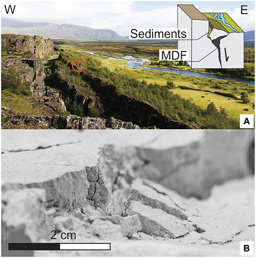
Figure 1. Examples of massively dilatant faults in nature and experiment. (A) Thingvellir Fault in Iceland. For exact location see Figure 10. Red circle shows four geologists for scale. Top right shows sketch of fault geometry. The river flows on the hangingwall. Between hangingwall and footwall Massively Dilatant Faults (MDF) develop, which may be several tens of meters wide. These open fractures may be partly filled with sediments, water, ice or lava flows. Close the surface tilted blocks can form. (B) Experiment in hemihydrate powder shows open fractures and tilted blocks similar to the geometries observed in the field. Quantitative mapping of the geometry of analog examples may provide insights on the kinematics and deep structure of the system.
Experiments
Experimental Setup
To test the effect of obliquity on normal fault evolution we designed a new apparatus that allows for adjusting obliquity on a rigid basement fault in 15° steps. We use a single basement fault dipping at 60°, modeling structures at a single rift shoulder. The box has no lateral walls and the sample is set up with natural slopes in strike direction. Because of the slopes, the 70 cm wide sandbox provides fault length of about 40 cm (Figure 2). An advantage of this setup is the experiment is not affected by friction of sidewalls influencing the evolving geometries.
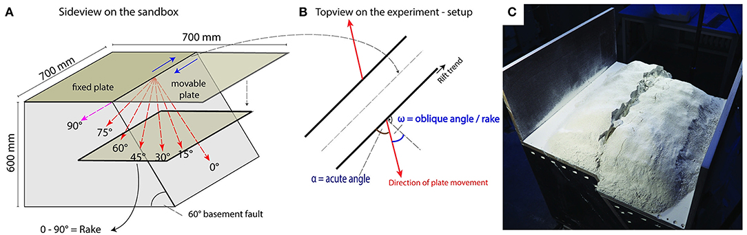
Figure 2. Experimental setup. (A) The box consists of a stable block and a hangingwall block that can move at different obliquities ranging from dip-slip to strike-slip. Angle of the of basement fault has been set to 60°. (B) In top view, the rift trend is parallel to the basement fault, obliquity ω is defined as the angle between dip direction of the basement fault and direction of plate movement (i.e., ω = 0° for dip-slip, and ω = 90° for strike-slip; a dip-slip fault has no or 0° of obliquity). (C) Example picture of an experiment with 45° obliquity. Note the box does not have sidewalls, and thus the fault is unencumbered by sidewall friction.
The box is driven by a geared motor to displacements of up to 70 mm. Our experiments are rate independent; we chose a speed of 3 mm/min so that fault evolution is captured in pictures taken in 10 s intervals. We use high-resolution digital single-lens reflex cameras to monitor the experiment. We use top- side- and front-view time lapse photography to create digital elevation models using “structure from motion” technique (Westoby et al., 2012), which allows for analyzing the structure of the fault zone in 3D. We use a vacuum cleaner to excavate parts of the fault zone from the top in order to look at the fault surface at resolutions much higher than by CT-scanning (Holland et al., 2006). This method has limitations: loose fragments of fault rock, bifurcations of the fault surface and parallel fault planes can produce structures which are difficult to interpret. Alternatively, we fill the open fractures with fine grained (<0.2 mm) sand to stabilize the structures. The experiments can then be sliced horizontally; however small open fractures and fractures which were not filled with sand may become damaged during excavation. Combining both excavation routines provides insights on the width of the fault zone and the distribution of open fractures down-dip.
We performed a first set of seven experiments with hemihydrate powder thickness of 20 cm and obliquity angles of 0°, 15°, 30°, 45°, 60°, 75°, and 90°. 0° obliquity corresponds to a dip-slip experiment; 90° corresponds to strike-slip faulting without a normal fault component. In a second set with a total of 20 experiments we used the same angles of obliquity but reduced powder thickness to 10 cm. We repeated the 10 cm hemihydrate experiments to test their reproducibility and to apply the different excavation methods. A third series was performed with a 10 cm thick layer of a 1:10 wt% hemihydrate-sand mix, also testing the seven different obliquities from 0 to 90°.
To analyze the results quantitatively, we use top view images of the time when the first visible fractures form, and images captured at 24 mm displacement. The latter is a stage where the fault has reached a mature phase, i.e., further extension is almost exclusively accommodated by widening of pre-existing fractures.
Material Properties and Scaling
Fine powders provide the cohesion and spatial resolution required to investigate dilatant fault processes (Walter and Troll, 2001). Holland et al. (2006) and Galland et al. (2006) REF presented the first experiments with full analog material characterization and thus a more complete understanding of the scaling relationships. Since then, different fine powders have been extensively used to model fractures in cohesive materials (Walter and Troll, 2001; Galland et al., 2006, 2015; Rodrigues et al., 2009; Gressier et al., 2010; van Gent et al., 2010; Holland et al., 2011; Trippanera et al., 2014). We use pure hemihydrate (CaSO4*1/2 H2O) powder for our experiments, which is commercially available “Probau Baugips.” In a second experimental series, we use a 1:10 wt-% sand-powder mixture (1:10 mixture hereafter). This material has a 6.6 times lower cohesion than pure hemihydrate powder, representing weaker materials such as hyaloclastites, ashes, or scoria.
To characterize the materials, we measured densities and performed shear tests for normally consolidated and over-consolidated material, following the procedures of Holland et al. (2006) and van Gent et al. (2010). To characterize the tensile strength of cohesive powders at varying normal stresses, we constructed a tensile strength measuring setup similar to the Tensile Strength Tester (TST) of Schweiger and Zimmermann (1999). Table 1 shows the results of material characterization. Shear tests and tensile strength measurements can be combined in a Cam-Clay type model (Roscoe et al., 1963; van Gent et al., 2010). This plot (Figure 3) summarizes material properties, showing friction angle, tensile strength and cohesion as a function of over-consolidation.
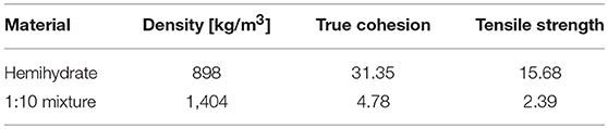
Table 1. Mechanical properties of analog materials.
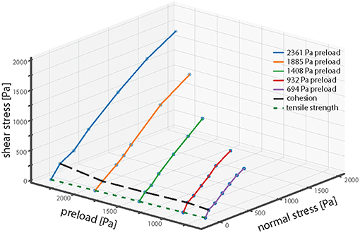
Figure 3. Combination of material characteristics in a cam-clay type plot. Normal stress is plotted on the x-axis, shear stress along the y-axis. Along the z-axis, pre-loading is plotted. Stippled green line represents tensile strength, stippled black line is cohesion.
To determine the scaling factor, the density and strength of Icelandic basaltic rocks were used, as these rocks represent the natural prototypes of the experiments. Using the scaling relationships of Hubbert (1937) and the cohesion and density of pure hemihydrate powder, 1 cm in the model would represent ~500–2,800 m of intact basalt, depending on chemistry or degree of weathering (see Table 1 for material properties and Supplementary Data Sheet 1 for detailed discussion and scaling calculations). However, for modeling large-scale systems, bulk rock strength must be considered. Cohesion of basaltic rock mass is one to two orders of magnitude lower than the value for intact rock (Schultz, 1996). This is because consists not of a homogenous rock package but an intercalation of effusive and eruptive lavas of different origins, variable thicknesses, and different degrees of fracturing. Consequently, 1 cm of the hemihydrate represents ~50 m of basalt (Table S1). This value matches observations in the field, where scarps of that height are common (Figure 1).
Strength of the 1:10 mixture is 6.6 times weaker than the hemihydrate strength. This is similar to the strength contrast between intact basalt and weathered basalt or hyaloclastite or scoria. Thus, the 1:10 mixture is suitable to model weak rock as commonly outcropping in Iceland (Figure 1). 1:10 mixture is an alternative to crashed quartz sand, which is another material commonly used to model cohesive rocks (Galland et al., 2015). Details on material characterization and scaling are provided in the Supplementary Data Sheet 1.
Results
For all experiments, we provide time-lapse videos in the digital appendix. All experiments have the same boundary conditions, that is a 60° dipping basement fault and no sidewalls along strike the fault. They differ in the amount of obliquity. Here, we first report results of hemihydrate powder experiments, Structures for the two sets of 10 and 20 cm powder thickness are very similar, why it makes sense to discuss them jointly. We then compare these with results from 1:10 mixture experiments, before reporting (semi-) quantitative results of all experiments.
Hemihydrate Powder Experiments
Surface Structures
En-échelon fractures are the earliest structures that develop in all but pure dip slip experiments after ~2 mm of displacement (Figure 4). They develop above the basement fault, as well as above future antithetic faults. At low obliquities (0° and 15°), orientation of the earliest fractures is largely parallel to the basement fault. At obliquities of 30° and larger, en-échelon fractures form. Their orientation is variable, depending on the angle of obliquity (Figure 5). In experiments with obliquities between 15 and 45°, en-échelon structures are soon linked to form a through-going main fault. Both, underlapping and overlapping of fractures occur, leading to different linkage mechanisms. In most cases, fracture segments coalesce via hard linking of single underlapping fractures. Overlapping fractures develop into relay ramps that often breach during progressive deformation. Underlapping fault-parallel fractures often continue to grow parallel to the basement fault until they link with another fault segment along strike (see Supplementary Videos). En-èchelon fractures in the experiments with high obliquity (>60°) eventually also link to form a through-going fault, but linkage occurs after 5–10 mm of displacement (Figure 5; Supplementary Videos). En-échelon fractures form not only during early stages of deformation, but also develop later in the graben center (Figure 5). If orientated approximately perpendicular to the direction of relative movement of the hanging wall, dilatancy of these fractures increases gradually during the experiment. Generally, orientation, curvature, location as well as amount of en-échelon fractures control main fault evolution as individual segments link during progressive deformation.
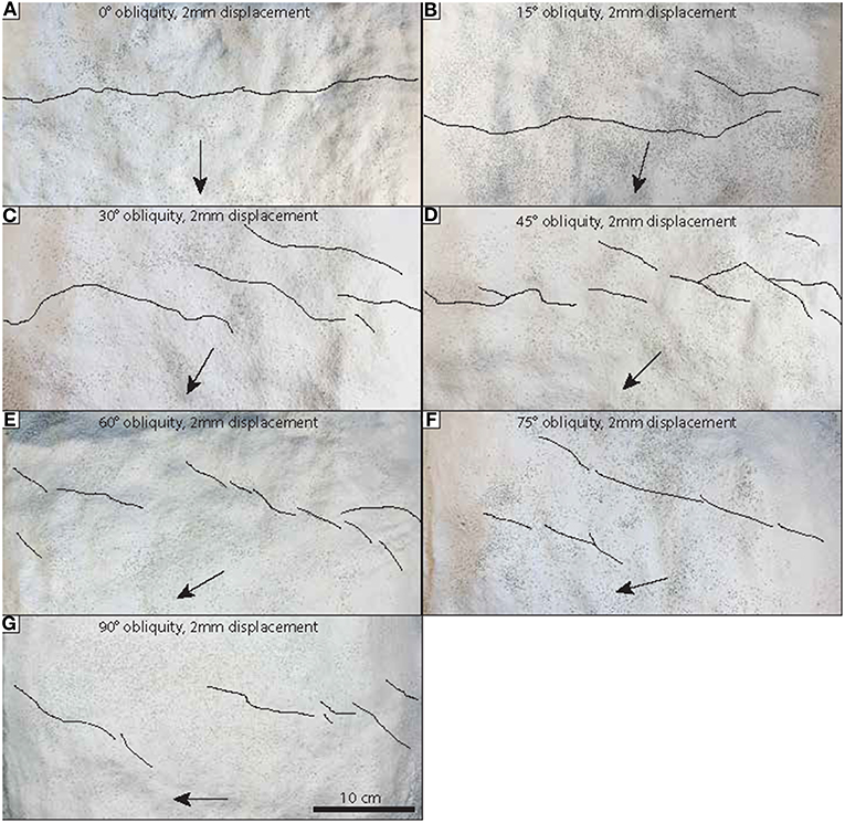
Figure 4. Compilation of mapped initial fractures. With increasing obliquity, fracture orientation changes progressively. (A–G) Obliquity increases from 0 to 90°; fractures mapped after 2 mm displacement. These early fractures control geometries of mature faults. Experiments with 20 cm hemihydrate thickness. Black arrows denote movement direction of the lower plate.
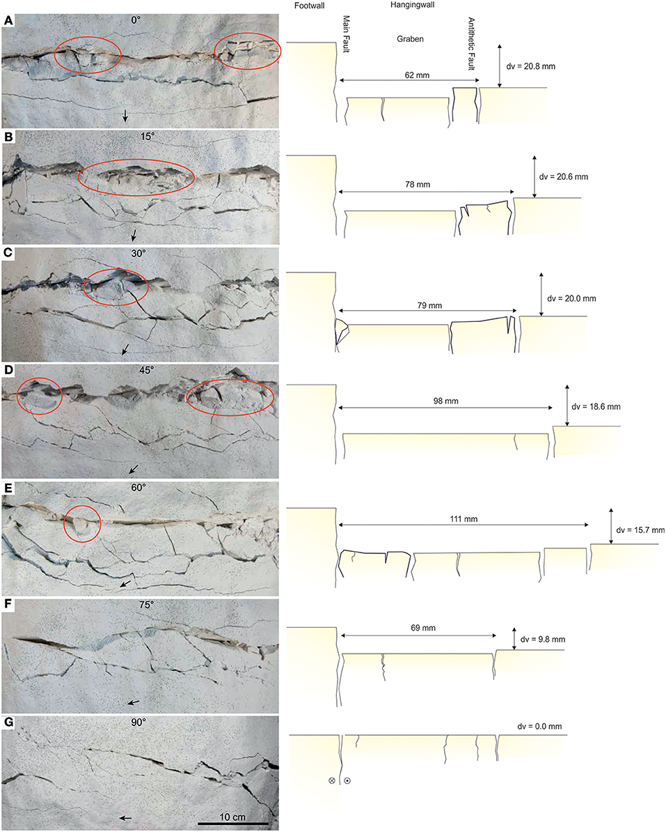
Figure 5. Top view of final stages of 20 cm powder experiments and schematic cross section perpendicular to basement fault strike. (A–G) Obliquity increases from 0 to 90°. Same experiments as shown in Figure 4. Pictures were taken after 24 mm of deformation. This is a stage where the fault has reached a mature phase, i.e., further extension is almost exclusively accommodated by widening of pre-existing fractures. At obliquities between 0 and 60° a graben forms between the main fault and the antithetic fault on the hangingwall. At low obliquities, the entire fault shows dilatancy, whereas at higher obliquities dilatancy is restricted to releasing bends. Note how final fault geometries are influenced by orientation of early fractures (Figure 4). Red circles denote tilted blocks. Cross sections show vertical throw associated with fault movement (dv), and average widths of grabens.
Influence of strike-slip motion is most pronounced in all 75° and 90° obliquity experiments, where a set of R-shears forms at an angle between 15° and 30° to the underlying basement-fault. Because of linkage of en-échelon fractures during progressive deformation, fault geometries resemble a zig-zag pattern (Figure 5). Long R-Shears in experiments with obliquity of 75° and 90°, result in large wavelength of the structure (Figures 5F,G; Figure S3).
During progressive deformation, fractures step into the footwall, incorporating individual blocks of the main fault into the graben structure. This results in formation of tilted blocks and breached relay structures and thus decreasing fault sinuosity (defined as the curvilinear length of the fault divided by the linear distance between two points). This is most pronounced in experiments of 30–60° obliquity. This is surprising, as intuitively this effect may be expected to be highest for experiments with highest obliquities. However, in experiments of 75–90° obliquity, R-shears instead of early en-échelon fractures dominate final geometry (Figure 5; Supplementary Videos). Generally, in pure powder experiments, the final geometry of the main fault is established after 24 mm displacement.
Because the fault dip in the model is steeper than basement fault dip, antithetic faults develop, resulting in graben structures. Antithetic faults are prominent features that are observed in all experiments except in 75°-90° powder. Antithetic faults form commonly after 4–10 mm displacement (see Supplementary Videos). Consequently, total displacements and apertures are smaller, ranging between 1 and 5 mm. At antithetic faults, tilted blocks are rare. Resulting graben geometries, sizes and formation mechanism differ between the individual experiments. Grabens do not form in strike-slip experiments and are rare in 75° experiments. At low obliquities, narrow and deep grabens form, as observed in the 0° 10 and 20 cm powder experiments (Figure 5).
Dilatancy along the main fault has been observed in all experiments with hemihydrate powder (Figure 5). The amount and localization of dilatancy depends on obliquity, sinuosity, cohesion of the material, and presence or absence of tilted blocks. Tilted blocks are typical features formed at the model surface. They are features developing at the hangingwall and tilting toward the graben center. In high obliquity experiments, tilted blocks are bound to transtensional areas (releasing bends) and are absent in strike-slip experiments. Tilted blocks form in different amounts and sizes, show different amount of tilting as well as variable degrees of fragmentation. There is no clear relationship between amount of tilt and amount of displacement. In many low-obliquity experiments, the blocks rotate back toward the hangingwall during late stages of deformation or collapse into dilatant faults. They always dip approximately at 90° to the basement fault; we observe no variation of block orientation with increasing obliquity. In powder experiments, dilatant faults particularly fill where tilted blocks collapse. Where no tilted blocks form, wide dilatant fractures are present, and may be stable during the entire experiment.
Increase of obliquity changes the amount and location of dilatant parts along the main fault. The higher the angle of obliquity, the more dilatant releasing bends develop. In restraining bends, dilatancy is negligible. This effect becomes most pronounced at obliquities of 75 and 90°. In these experiments, open fractures are isolated. These fractures remain open during the entire experiments, as no tilted blocks form. Where restraining and releasing bends are less well-developed, the fault is open along its entire length.
Fault Plane and 3D Structure
To determine dilatancy at depth and to inspect individual fault surfaces, we excavated two experiments with 15° and 60° fault obliquity (Figure 6). It was only possible to excavate powder experiments, as the 1:10 mixture immediately collapsed and filled all open fractures. Open fractures exist down to depths of 6–8 cm, and can be linked to the surface or are found below collapsed tilted blocks. Dilatant fractures are interconnected along the entire fault in experiments with low obliquities. In the graben center, open fractures are observed down to a depth of 10 cm. Generally, the amount and size of dilatant fractures decreases with depth. Smaller fractures are rapidly filled with debris, particularly in areas where tilted blocks collapse. The deepest cavities of up to 12 cm have been preserved at antithetic faults. Dilatancy close to the surface is much lower as compared to the main fault, and thus more easily filled at shallow depths. This prevents loose material from reaching the lower parts. Furthermore, because tilted blocks are rare, the amount of debris falling into the fault is relatively small. Consequently, permeability of the antithetic faults may be higher at depth as compared to the main fault, both in 15° and 60° obliquity powder experiments. While rubble fillings partly clog the entire main fault, antithetic faults show connected cavities along strike (Figure 6).
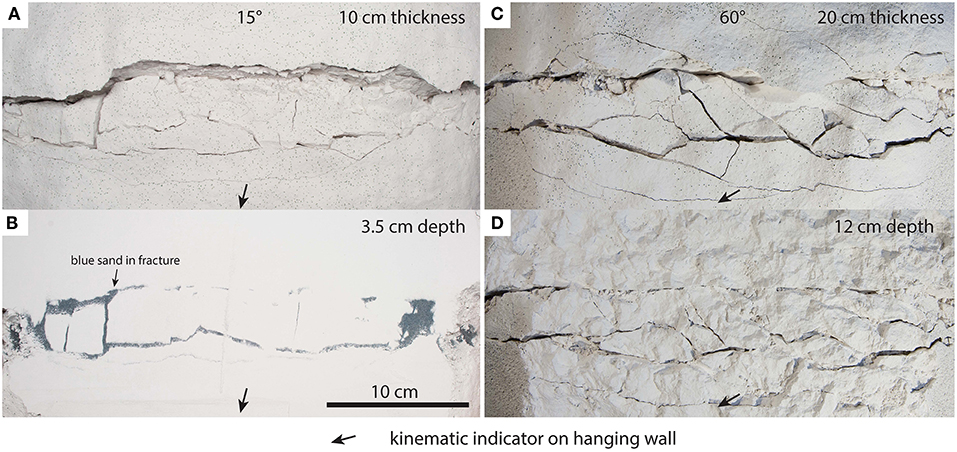
Figure 6. Excavated experiments. Two excavation techniques have been applied to visualize open fractures at depth. First, open fractures were filled with dyed sand, and the experiment was sliced from top to bottom. (A) Top view on surface structures of experiment with 10 cm powder thickness and 15° obliquity. Down-thrown block at bottom, arrows indicate direction of movement. (B) Excavated experiment. Blue sand filled the open fractures at depth. At 3.5 cm wide open fractures exist at depth. Tilted blocks at the hangingwall collapsed and reduce area fraction of open gaps at the main fault. The antithetic fault remains open. (C) Top view of powder experiment with 20 cm powder thickness and 60° obliquity. (D) Surface excavated with vacuum cleaner. Vacuum cleaning results in more rugged surface as opposed to slicing, but small open fractures are unencumbered by the excavation process. Similar to (B), the area fraction of open gaps is larger at the antithetic fault, as the main fault is filled with debris of collapsing tilted blocks.
With increasing obliquity, dilatancy along the main fault is often restricted to releasing bends at the surface, separated by intensively sheared zones. Consequently, dilatancy close to the surface becomes smaller with increasing obliquity. Releasing bends can remain open at depth as due to absence of tilted blocks little debris is filling them. This results in the (somewhat counterintuitive) general trend that faults with intermediate to high obliquities show dilatancy at greater depths than less oblique faults and a high vertical permeability. In all experiments, the area fraction of dilatancy decreases with depth.
Excavated fault planes show slickensides on the surfaces of shear fractures, tracing the moving direction of the hangingwall block (Figure 7). Slickensides are observable in all experiments. In strike slip experiments, they are observed from close to the surface down to the bottom of the experiment. In dip-slip experiments, they only occur at depths >5 cm, as closer to the surface only dilatant fractures occur. Size of the slickenside planes is variable along strike individual slip planes, and may range between few millimeters to centimeters.
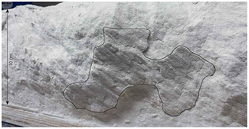
Figure 7. Slickensides on an excavated fault surface of a hemihydrate experiment. Slickensides are best visible in the encircled area, and absent in dilatant parts of the fault.
Sand-Powder Mixture Experiments
Results from 1:10 mixture experiments, scaled to weaker rocks such as hyaloclastites or scoria, can be compared to powder experiments (Figure 8). Generally, the 1:10 mixture experiments display similar surface structures as observed in experiments with hemihydrate powder only. These include the formation of cliffs, tilted blocks, (breached) relays, dilatant faults, antithetic faults, local areas of extension and compression as well as en-échelon faults and R-shears. We observe the strain is more localized in a narrow band around the basement fault trace. The influence of obliquity on the geometry and curvature of the antithetic fault is much smaller as compared to the hemihydrate powder. Generally, dilatant parts in the 1:10 mixture experiment are quickly filled as the sidewalls rapidly loose cohesion.
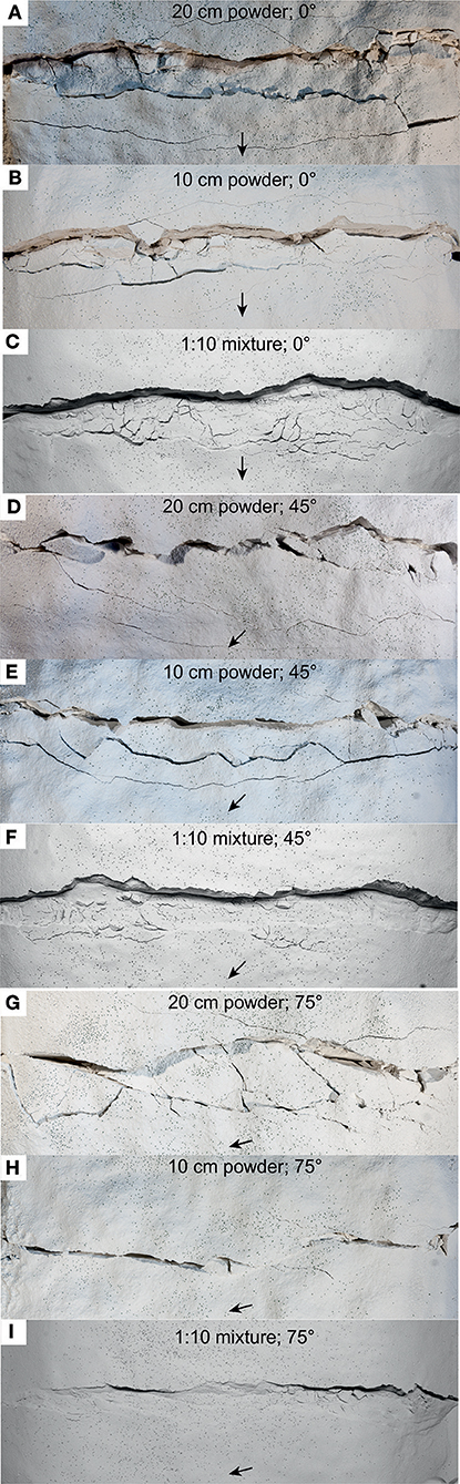
Figure 8. Comparison between experiments with different powder thickness and material strength. (A–C) Experiments with 0° obliquity. In 20 and 10 cm powder experiments, open fractures form on both sides of a central graben between main and antithetic fault. Tilted blocks from that may collapse and fill parts of the fault with rubble. In weaker material (1:10 mixture) open fractures are rapidly filled with material collapsing from the sidewalls (C). Vertical cliffs form, but open fractures are only sustained close to the surface. (D–F) Experiments with 45° obliquity. A shallow and wide graben forms in the 20 cm powder experiment; the influence of early en-échelon fractures is visible in the hangingwall. Dilatant fractures at the surface are less continuous and narrower as compared to the experiments with 0° obliquity. In the 10 cm and 1:10 mixture experiments, a narrow graben forms (F). Rotated and collapsed blocks oriented parallel to the basement fault are visible in all experiments. Dilatant fracturing in the 1:10 mixture experiments is much lower than in powder experiments. (G–I) Experiments with 75° obliquity. Typical strike-slip structures occur and fault geometry is dominated by orientation of R-shears. Dilatancy in powder experiments is most pronounced at releasing bends. Width of the fault zone decreases in the 1:10 mixture experiments (I).
Like in the powder experiments, en-échelon fractures are the first observable structures at the surface. However, while in powder experiments fractures form over a large area they are mainly restricted to a narrow band in the 1:10 mixture experiments. In experiments with 30° obliquity and higher, underlapping fault segments do not link during early stages of the experiment. Instead, they continue to grow subparallel to each other, forming overlapping fault segments that are subsequently linked by the formation of a relay. During late stages of the experiments, these relays are breached and a through-going main fault forms (Figure 8, see also Supplementary Videos). Generally, in pure powder experiments, the final geometry of the main fault is established after 2 mm displacement. In 1:10 mixture experiments geometries change until 20 mm displacement.
Similar to powder experiments, in 1:10 mixture experiments grabens develop between main and antithetic fault except at high obliquities. Antithetic faults form generally after 4–10 mm displacement. The graben in 1:10 mixture experiments shows a decrease in graben width with increasing obliquity at lower obliquities as compared to powder experiments (Figure 9). At higher obliquities (>45°) 1:10 mixture experiments also show restraining and releasing bends, but apertures are much smaller than in the pure powder experiments and the open parts are less connected. The 75° 1:10 mixture experiment shows a distinct shear zone in its center without any opening (Figure 8). In summary, weaker material shows similar structural elements but observed geometries are often less pronounced than in powder experiments (e.g., smaller tilted blocks, narrow graben). Often features occur only transiently (Supplementary Videos), as sidewalls loose cohesion. Even small vibrations during the experiment can lead to a total disintegration of structures.
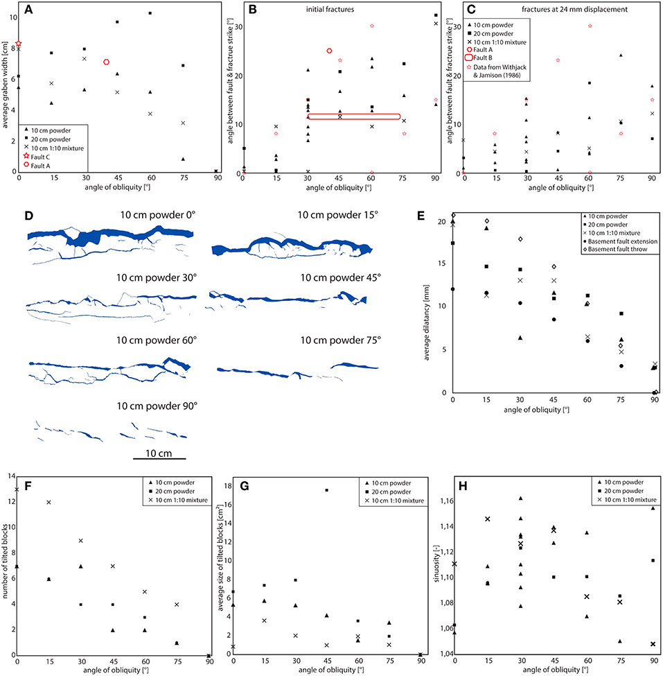
Figure 9. Quantitative evaluation of all experiments. (A) Average graben width (i.e., the distance between the main fault and the antithetic fault) for experiments with 10 and 20 cm powder thickness and 1:10 mixture experiments as a function of obliquity. Graben width is constant or slightly increasing for low to medium obliquities and drops to zero at high obliquities. No graben forms in strike-slip experiments. Faults (A,C) are natural examples from Iceland (Figure 13). (B) Orientation of initial fractures for different obliquities as observed in experiments, as measured after 2 mm of displacement. Progressive change of strike direction can be seen until ~45°, after which the orientation is roughly constant at an angle of 15 ± 5° with respect to the basement fault. Red markers represents fracture orientation observed at an evolving fault in Iceland. (C) Orientation of fractures as observed after 24 mm of displacement in experiments. Mean strike values are variable, but a general trend with increasing obliquity can be inferred. The values measured in our experiments are similar to values obtained from soft clay models (Withjack and Jamison, 1986) (D) examples of dilatancy as determined in 10 cm powder experiments. Top view of experiments, blue areas are dilatant parts. (E) Quantification of changes of dilatancy with increasing obliquity. The general decreasing trend can be seen in all experiments. Dilatancy scales with horizontal displacement on the basement fault (black dots). (F) Number of tilted blocks plotted vs. fault obliquity. A general decrease is observed. The size of tilted blocks remains constant for low obliquities, but decreases slightly when obliquity is larger than 45° (G). This trend is less apparent for 1:10 mixture experiments. (H) Fault sinuosity as a function of obliquity.
(Semi-) Quantitative Analysis
For quantitative analysis, we determine dilatancy, graben width, fracture distribution, sinuosity (defined as the ratio of the curvilinear length of the fault trace divided by fault length), and the shape and distribution of tilted blocks along strike the fault. Results of quantitative analysis are provided in Figure 9.
Graben width correlates with obliquity (Figure 9A). With increasing obliquity, grabens first tend to become slightly wider before decreasing at obliquities >45° for 10 cm powder experiments, and obliquities >60° for 20 cm powder experiments, respectively. Expectedly graben width is zero for 90° obliquity, i.e., strike slip faulting without normal fault component (Figure 9).
To characterize fracture orientation, we report mean azimuth with respect to the basement fault and length. Orientation of early fractures in dip slip experiments is dominantly parallel to the basement fault, as expected. With increasing obliquity en-échelon fractures form and the strike of the fractures changes progressively, until it stabilizes at an angle of 15 ± 5° with respect to the basement fault (Figure 9B). At final stage of deformation and zero obliquity (dip-slip deformation), fractures longer than 6 mm are oriented parallel to the basement fault. Smaller fractures occur in all directions. With increasing obliquity, fewer small fractures are observed, particularly in the graben, and their orientation is more similar to that of the main fault. Strike of fractures progressively changes with increasing obliquity, to a deviation of ~20° from the basement fault in strike slip experiments (Figure 9C). This is consistent with expected orientations of R-Shears. In all experiments, the area between main and antithetic fault is progressively more fractured during the experiments. Therefore, mean fracture length does not change during the experiments.
A general decrease in fault dilatancy with increasing obliquity can be observed in all experiments (Figures 9D,E). The thickness of the powder layer does not change measured dilatancy, as it depends on slip of the basement fault (as opposed to graben width, which correlates with layer thickness). Similarly, dilatancy measured in pure powder experiments is comparable to values in 1:10 mixture experiments, and depends on the amount of horizontal displacement on the fault. However, dilatancy determined at the surface is always higher than the horizontal displacement at the basement fault. This is an exciting observation, as it implies it is not straightforward to determine the amount of fault slip by measuring dilatancy. As observed in the sliced experiments, dilatancy deceases with increasing obliquity, as it is successively more concentrated in releasing bends in strike slip setting.
Closely linked to the amount of dilatancy is the number of tilted blocks along the main fault (Figure 9F). We counted the number and measured sizes of tilted blocks in 10 cm powder, 20 cm powder and 1:10 mixture experiments. The number of tilted blocks decreases with increasing obliquity. 1:10 mixture experiments show consistently more tilted blocks as compared to pure powder experiments. This is because the lower cohesion of the material results in fractionation of the blocks during the experiment. The size of tilted blocks is constant for low obliquities, but decreases at obliquities >45°. This trend is less apparent for 1:10 mixture experiments; size of tilted blocks in 1:10 mixture experiments is lower than in powder experiments. Blocks are largest at low obliquities and in 20 cm powder experiments (Figure 9G). During progressive deformation, tilted blocks are successively disintegrated. Consequently, the volume of open voids at the final stage of deformation is lower the more tilted blocks formed.
We determined sinuosity (defined as the ratio of the curvilinear length of the fault and its length) of the main fault in all experiments from mapping fault traces (Figure 9H). In powder experiments with 10 cm powder thickness, fault sinuosity increases for obliquities from 0 to 60°, followed by a decrease. This pattern evolves because early fractures and their linkage influence sinuosity (see also above). In low obliquity experiments, early fractures are oriented approximately parallel to the basement fault, resulting in a main fault with low sinuosity after early fracture linkage. With increasing obliquity, en-échelon fractures form, progressively deviating from basement fault strike (Figure 9B). Linkage leads to successively higher sinuosity of the mature fault. At obliquities of 60° and higher, initial fractures are crosscut by the later main fault, resulting in a sinuosity decrease. In experiments with 20 cm powder thickness, the decrease occurs already at 45°; for 1:10 mixture experiments, sinuosity of experiments with low obliquity is higher than observed in powder experiments. Despite these general trends, considerable variation of sinuosity can be observed in the repeated experiments (Figure 9H). This is because local material heterogeneities influence fault geometry. This implies that for individual faults, sinuosity is not always a good measure to determine fault obliquity. In summary, our analyses show the angle of obliquity influences fault geometry systematically. Parameters particularly indicative for obliquity are orientation of initial fractures, graben width, dilatancy at the surface and at depth, and number of tilted blocks. In this study, we focus mostly on dilatant structures, as other parameters have been studied earlier (see e.g., Acocella, 2014 for a recent review).
Discussion
Analog Models
A general observation in our experiments is that the geometry of the fault is strongly affected by the orientation of the initial fractures. Location, orientation and densitiy of en-échelon fractures then affects the formation of tilted blocks, graben geometry, and fault sinuosity in the massively dilatant zone. The location of initial fractures is strongly dependent on local heterogeneities in the model material, and this has also been seen in DEM models (Abe et al., 2011). In the natural prototype, this corresponds to the state of jointing in the basalt (Holland et al., 2011). This implies that much of the variability of fractures is controlled by heterogeneities in the model material.
In our experiments, the deepest open fractures that can be followed along strike (i.e., the massively dilatant part of the fault) form to a depth of 5–9 cm in hemihydrate powder. Down to this depth no slickensides were observed. Below this, in the hybrid fracture zone, open fractures occur together with slickensided patches. Using our scaling relationship, the failure mode transition in the Iceland basalts occurs at depths of 250–450 m, possibly down to 1.5–2 km for stronger intact rock (see details on scaling in the Supplementary Data Sheet 1). Considering a tensile strength of 6 MPa and a mean density of 2,400 kg/m3, Acocella et al. (2003) calculate the depth of failure mode transition to occur between 260 and 780 m, which is similar to our results. Depth of open fractures are comparable to estimates of Gudmundsson (1992), Acocella et al. (2003), Grant and Kattenhorn (2004), or Hardy (2013), who predict open fractures in basalts to occur down to depths of up to 800 m, c. 500 m, and several hundred meters, respectively, depending on tensile strength and rock density.
In our hemihydrate powder models, dilatant jogs still exist at the base of the box, i.e., at a depth of 20 centimeters, independent of fault kinematics. For intact basalt rock, this suggests that in dilatant jogs in normal faults may exist down to depths of ~5 km and possibly deeper. Weak materials such as hyaloclastite or scoria are not able to sustain open fractures, at these depths. Consequently, depending on the material involved in the faulting process, as well as its degree of fragmentation and weathering, different depths of failure mode transition may occur in nature. Interlayering of weak and strong materials, as often observed in rift systems, will result in a complex failure mode transition zone that can be spread out over hundreds of meters (Smart and Ferrill, 2018).
The observation of dilatancy is consistent with findings of earlier studies, using hemihydrate powder and a dip-slip experimental setup (Holland et al., 2006; van Gent et al., 2010; Kettermann et al., 2016). This study shows additionally that obliquity influences the location of dilatant patches at depth and at the surface. While dip-slip experiments show a continuous connection of open fractures at the surface, strike-slip experiments show open fractures only in releasing bends. Average dilatancy at the surface reduces approximately linearly with increasing obliquity for the same slip vector (Figure 9E). In dip slip experiments, tilted blocks form, which are later disintegrated and fill the open fractures with rubble. With increasing obliquity, smaller tilted blocks form, and they have not been observed in our strike slip experiments. Hence, the open fractures are not filled with collapsing material.
Our models build on previous work that showed how obliquity influences rift geometries at crustal to outcrop scale. Discrete element models by Deng et al. (2018) show how fracture patterns at the surface are affected by a pre-existing weakness. Based on analog models, Withjack and Jamison (1986) predict maximum extension direction at oblique rifts (which is perpendicular to orientation of early en-échelon fractures) is a function of the angle between rift trend and displacement of the rift walls. This relationship has been corroborated in clay models and field data in Iceland (Clifton and Schlische, 2003), and is also observed in our experiments (Figures 9B,C). Furthermore, it has been suggested that fault sinuosity depends on obliquity, and reaches a maximum at 60° obliquity (Clifton et al., 2000). This agrees with findings of our study (Figure 9H). However, our experiments show that fault sinuosity is variable, and depends on location of early fractures, their position with respect to the basement fault, and fault linkage processes. Particularly early fracture localization depends on small scale heterogeneities, and fault linkage processes do not depend on obliquity but on the local stress field and its variation (e.g., Mansfield and Cartwright, 2001; Clifton and Kattenhorn, 2006), as well as on the amount of stretching (Acocella et al., 2005); see Fossen and Rotevatn (2016) for a review. Sinuosity values obtained in our experiments vary between 1.05 and 1.16. For clay experiments; Clifton et al. (2000) obtained values between 1.4 and 2.26. The higher values are a result of two linking fault populations, whereas in our experiments sinuosity mostly depends on linkage of en-échelon fractures. As observed in our experiments and reported from field data (e.g., MacDonald et al., 1979; Kureth and Rea, 1981), sinuosity of the fracture zone in transform settings controls formation of releasing and restraining bends along the fault, which in turn influence dilatancy at depth.
Oblique Faults on Iceland
The results of our study may be applied to faults on Iceland located on the Mid Atlantic Ridge. Iceland is the only place on Earth where a mid ocean ridge is exposed above sea level, atop the extensional plate boundary separating the North American plate and the Eurasian plate. The reason for the aerial exposure of the Mid Atlantic Ridge in Iceland is the presence of a mantle plume, the Icelandic hotspot (Kaban et al., 2002). This mantle plume is the cause for increased volcanic activity and a wider, more complex deformation zone compared to oceanic plate boundaries where no plume activity occurs, as the relative movement of the plate boundary with respect to the Icelandic hotspot leads to rift jumps and unstable boundaries (Einarsson, 2008).
The mid-Atlantic ridge breaks up into a series of more of less oblique segments on the Icelandic main land (Figure 10). Zones of active rifting in Iceland are indicated by increased volcanic activity. Some of the rifting segments are purely divergent and characterized by normal faulting and fissuring. This type of fracturing and volcanism is observed in the Northern Volcanic Zone, and in two sub-parallel rift zones in South Iceland, the Western and Eastern Volcanic Zones, respectively. Other segments of the rift are transform zones characterized by strike-slip movement, such as the South Iceland Seismic Zone connecting the Western and Eastern Volcanic Zones, and the Tjörnes Fracture Zone in the North of Iceland. Additionally, oblique segments such as the Reykjanes Volcanic Belt are characterized by interlinked volcanism and strike-slip faulting (e.g., Einarsson, 2008; Savry and Cañón-Tapia, 2014). On Iceland dilatant faults similar to those observed along all mid ocean ridges are spectacularly exposed (e.g., Bubeck et al., 2017), Figure 11. It has been shown that these dilatant faults control fluid pathways and geothermal anomalies (Walter et al., 2018).
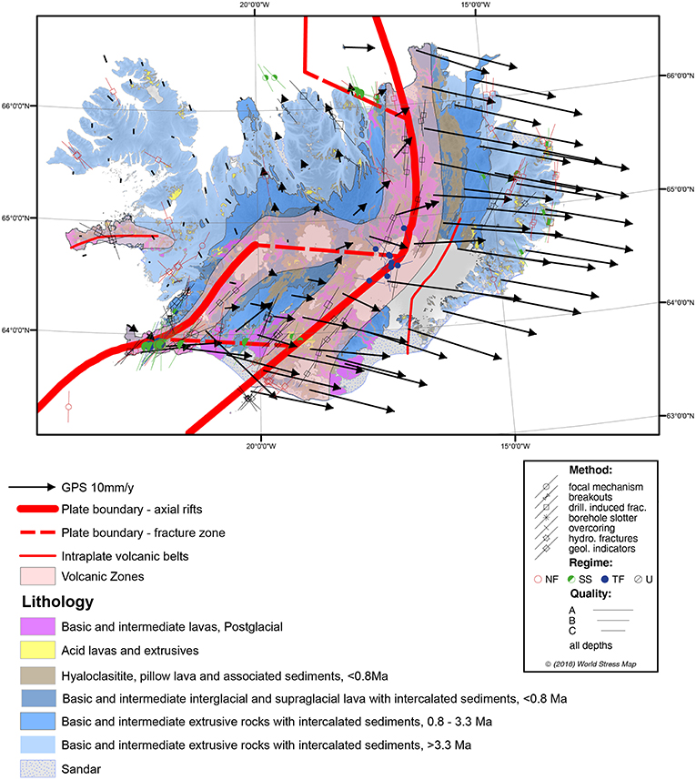
Figure 10. Geological map of Iceland including main fault strucutres and volcanic belts. RR, Reykjanes Ridge; RP, Reykjanes Peninsula; RVB, Reykjanes Volcanic Belt; WVZ, EVZ, and NVZ, Western, Eastern and Northern Volcanic Zone; TFZ, Tjörnes Fracture Zone; Thv, Thingvellir. Geological map modified after Jóhannesson (2014). Rift zones from Thordarson and Larsen (2007), GPS data from Árnadóttir et al. (2008), stress data from Heidbach et al. (2016).
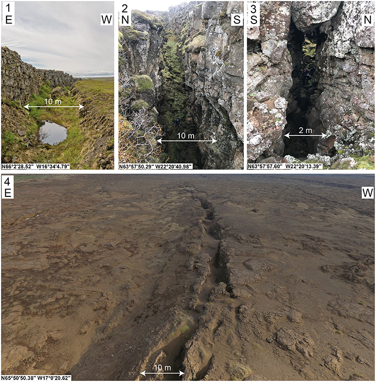
Figure 11. Field sites on Iceland that may be compared to our analog models. Field impressions show exceptional outcrop conditions of the rift system, allowing for high-resolution mapping of structures close to the surface. Apertures of open fractures at the surface range from few cm to several tens of meters, as for instance observed at the famous world heritage site of Thingvellir. Correlating both sides of the open fracture is commonly possible at fractures of widths of 10 meters or less. Fractures are partly filled with rubble. Image 4 was taken with an unmanned aerial vehicle. Note the tilted block in foreground of image 4.
The Reykjanes Peninsula is situated in the south-western most part of Iceland (Figure 10). It is the direct prolongation of the Reykjanes ridge, i.e., the region where the mid-Atlantic ridge hits land. It is the only onshore oblique rift segment of the mid-Atlantic ridge, with the plate boundary oriented at ~30% obliquity to spreading direction of the mid ocean ridge (Gudmundsson, 1987; Grant and Kattenhorn, 2004; Clifton and Kattenhorn, 2006; Villemin and Bergerat, 2013). The northern and western rift zones are dominated by axial spreading (Angelier et al., 1997; Friese, 2008; Sonnette et al., 2010; Hjartardóttir et al., 2012). In Thingvellir, located in the western rift zone, the rift axis trends approximately normal to the plate spreading direction at 30°. Similarly, the Krafla fissure swarm and the Theistareykir fissure swarm of the northern volcanic zone are also dominated by axial rift. Faults observed in Iceland show different amounts of dilatancy, ranging from several tens of meters to cm scale. Vertical depths of dilatant fractures measurable in the field can be >40 m, before the open fractures are filled with water, aeolian sand, or rubble (Figure 11). Vertical walls show lava flows with columnar joints and different degrees of fracturing, and weathering intensity varies. Particularly for large openings it is challenging to correlate geometries at the surface. Climbing into the open fractures allows correlations in deeper sections. Along all faults, tilted blocks occur, with lengths ranging from few to several hundreds of meters. As in our analog models, collapsing of the blocks into the open fractures can be observed. Relays and breached relays are common. Similar to our analog models, antithetic faults can be observed, with less vertical throw and dilatancy as compared to the main fault. In the Western Rift Zone, newly developing faults exist, showing en-échelon fractures as observed in our models. 1:10 mixture experiments may be compared to mechanically weaker rock, such as hyaloclastite, ignimbrites or tuff layers exposed in Iceland. These rocks are capable of supporting vertical cliffs but are much more prone to weathering. In weathered parts, no tilted blocks are preserved, and dilatant sections are often filled with rubble.
To quantitatively compare our analog models with nature, we focused on the Northern and Western Rift Zones, which offer exquisite outcrop conditions and good accessibility to faults (Figure 11). We used unmanned aerial vehicles to photograph the faults and successively create a digital elevation model at 5–15 cm resolution (Figure 12). In total, we cover an area of roughly 12 km2. Details on data gathering and DEM building are provided in the Supplementary Data Sheet 1. These high-resolution data sets enable us to characterize fault geometries in the models at the decimeter scale. The average graben width represents the mean distance between the bounding faults, measured along scanlines between the manually mapped graben boundaries in intervals of 1 m orthogonally to the average fault strike. Angles of obliquity are calculated from the opening width and horizontal displacement of associated features along the fault. The strike values for the faults and en-échelon fractures were calculated as linear directional mean from the vectors of the fault traces.
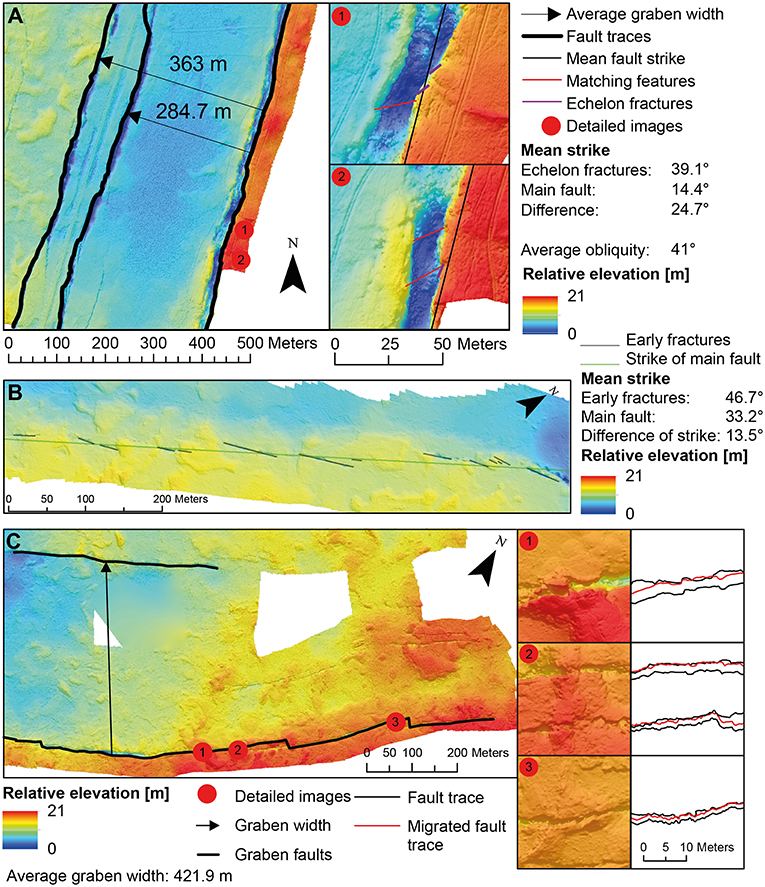
Figure 12. High resolution digital elevation models of the selected field sites where obliquity can be determined. Fault (A) shows two antithetic faulty that can be used for determining graben width. Insets 1 and 2 show how both fracture surfaces can be linked. Fault (B) shows a series of early fractures and their angle to the main fault. Early fractures are indicative for fault obliquity. Fault (C) shows no obliquity, as determined by matching the respective fracture surfaces on both sides.
We chose three faults, where geometries of dilatant fractures on both sides can be correlated to determine obliquity. Fault A is located in the Krafla Fissure Swarm (Kelduhverfi are) of the Northern Rift Zone, near the Asbyrgi canyon. Faults B and C are on the Reykjanes Peninsula in the Western Rift Zone. Fault B belongs to the Reykjanes and Fault C to the Vogar fissure swarms, respectively. Five en-échelon fractures were identified along fault A (in Asbyrgi), intersecting the main fault at an angle of 25°. Two antithetic faults are present, and the respective graben widths are 285 m for the proximal and 363 m for the distal fault. To quantify obliquity, we inspected geometries of the adjacent fault-plane traces and connected matching features. Fault A has an angle of obliquity of 41° (Figure 12). (The general extension direction in the area is orthogonal.) The 33° average strike direction of Fault B has been calculated from a vector from fault tip to fault tip of the analyzed segment. The initial en-échelon fractures were mapped as straight lines from fault tip to fault tip, from which the mean strike direction of all en-échelon fractures was calculated. Average en-échelon direction is 47°. Thus, the en-échelon fractures are oriented in an acute angle of 13.5° to the main fault. For fault C (Vogar) the mean graben width of 422 m has been measured from the main fault in the SE toward the next antithetic fault (Figure 12). The fault traces have been mapped and projected toward the adjacent fault trace to illustrate this fault has no oblique slip component. Measurements of graben width and orientation of early fractures are in good agreement with results from analog models (Figure 9). This suggests that structures are not only qualitatively but also quantitatively comparable, and thus the structures we observe at depth in our analog models are also present in the faults on Iceland. That surface structures in the field and the models are quantitatively comparable suggests structures at depth observed in the models are also present in nature. Figure 13 shows a conceptual model of geometries at faults with different obliquities, summarizing robust features of the models. In dip slip deformation, tilted blocks form and dilatancy occurs at the main and the antithetic fault. Early fractures are oriented parallel to the main fault. Tilted blocks may collapse, filling open fractures. Because at antithetic faults tilted blocks are rare, open fractures remain open. Below a depth of ~6–8 cm, the volume of open fractures decreases and they are often not connected. This depth of open fractures is consistent with predictions from the Mohr-Coulomb diagram and natural data from fractured rocks (Gudmundsson, 1992; Acocella et al., 2003; Trippanera et al., 2015). The open fractures are partly filled with debris from collapsing tilted blocks. In strike-slip kinematics, dilatancy is constrained to releasing bends. This results in lower connectivity of open fractures at the surface.
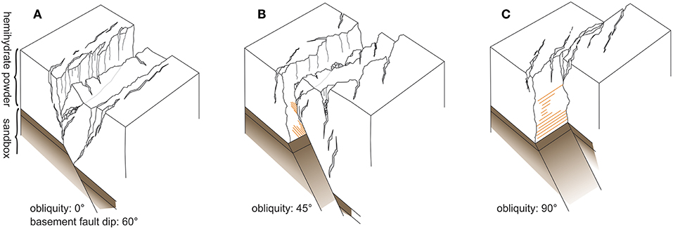
Figure 13. Generic model of the observed structures depending on obliquity. (A) Dip slip deformation. A graben develops and tilted blocks form. Dilatancy is large close to the surface and decreases with depth. Fractures strike roughly parallel to the basement fault. In the graben, fractures perpendicular to the fault form occasionally. Sinuosity of the main fault is low. Open fractures are connected along the entire fault. (B) Oblique slip deformation. Graben is less wide, and tilted blocks are smaller. Sinuosity is high and influenced by early en-échelon fractures. Dilatancy occurs close to the surface and at depth. Red lines show slickensides on the fault surface. (C) Strike-slip faulting. No graben is present, and dilatancy is bound to Riedl Shears and releasing bends. This leads to potentially higher dilatancy at depth as compared to dip-slip faulting.
Open fractures are present also at depths greater than predicted by standard mechanical models, reaching the base of our experiments. This implies the failure mode transition from dilatant to shear fracturing is a complex zone that may extend to depths of at least 1 km. Open fractures at depth are not connected along strike, but are separated by shear fractures. In our analog models this is witnessed by slickensides on the fault surfaces. During oblique slip early fractures are oriented at an angle to the main fault, which is increasing with increasing obliquity. This results in increasing sinuosity and possibly a decrease of connectivity of open fractures. Tilted blocks are smaller with increasing obliquity and are absent in strike-slip experiments. This influences the distribution of open fractures because collapsing tilted blocks fill open voids at depth. Releasing bends close to the surface and at depth can remain open where less tilted blocks are present. Dip-slip faults feature a pronounced decrease of dilatancy with depth, partly because of collapsing tilted blocks. Strike-slip faults do show a much weaker trend, and dilatant patches occur close to the surface and at depth.
This model may be applied to Iceland. We show that faults are dilatant to depths of several hundred meters. At depths below 450 m transition to shear fracturing occurs, and more intermittent dilatant fractures may exist at depths of at least one kilometer. Fractures may be well-connected at depth, and large caves may exist. At faults with an oblique component such as observed in the Northern Rift Zone and the Reykjanes Peninsula open fractures also exist at deep levels. However, their fracture network is less well-connected. Partly the faults may be more permeable at depth, as rubble fillings are less common. These findings extend our previous knowledge on the fault systems in Iceland and other rift zones (Figure 14). Close to the surface and down to depths of at least 450 m but as deep as the critical depth of ~800 m (Gudmundsson, 1992; Acocella et al., 2003), exclusively mode one fractures form. Below this, the failure mode transition to shear fracturing occurs. Our experiments show this is a complex zone in which locally open fractures may be maintained to depths of at least 1 km, however in dilatant jogs. The deepest possible occurrence of open fractures has yet to be determined. This depth is not only controlled by mechanical stratigraphy resulting from interlayering of lava flows and ash and scoria layers; lava flows themselves have different strengths depending on their degree of fracturing and jointing. Furthermore, the occurrence of open fractures at depth depends on fluid pressure (Townend and Zoback, 2000); in cohesive carbonates dilatant open fractures have been observed at depths of several kilometers, associated with high fluid pressures (Hilgers et al., 2006; Grobe et al., 2018). We are not aware of fluid pressure data from Iceland measured at depths >1 km and consequently as of now the depth below which open fractures can be maintained remains speculative.
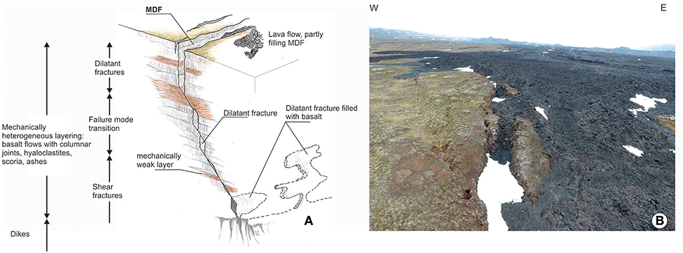
Figure 14. (A) Conceptual model of the results applied to a rift (not to scale). In the uppermost section down to a depth of up to 800 m only dilatant fractures occur in cohesive rocks. Below this critical depth, transition to shear fracturing can be observed. Dilatant parts of the fault are isolated patches. Location of these patches depends on the heterogeneity and mechanical stratigraphy of the rock column. At greater depths elevated pore pressures may result in Mode 1 fracturing. The depth below which only shear fracturing can occur is unknown. If extension is large enough the surface fracture connects with the dike system at depth and may guide magma ascent. This can result in fissure eruptions and lava flows filling the MDF (B).
Below the complex zone of failure mode transition only shear fracturing can occur. Ultimately, the faults are connected to the dike system that accommodates rift extension, as has been suggested by field studies in different rift systems (Nobile et al., 2012; Phillips et al., 2017), as well as and analog models (Trippanera et al., 2014; Galland et al., 2015). Modeling of dike intrusion into cohesive powders shows that surface fractures propagate from top to bottom, growing toward the upward-propagating dike (Abdelmalak et al., 2012). Strain analysis of the experiments show that at the tip of the dike shear bands form which connect to the surface fault during later stages of the experiments (Abdelmalak et al., 2012). Field evidence for these processes is rare, as outcrops are very limited. In Iceland, few outcrops of the deeper section of the rift system exists on the east coast of the Trollaskagi Peninsula in North Iceland (Gudmundsson, 2000). Here, primarily dikes and normal faults have been observed. In some areas the faults are only observed in the shallow part of the lithological column (Acocella and Trippanera, 2016). These may represent areas where the connection between the feeder dike and fracture has not yet been established, or where rifting was fast enough that a new dike formed before fracture and dike connected. However, as soon as the dike and fracture connect, dike propagation will be guided by the fracture (Magee et al., 2016). Our models suggest that dike propagation a within the failure mode transition zone may be guided by occurrence of open fractures in the subsurface (Figure 14). This may help understanding how dikes propagate through the fractured crust. Additionally these findings may help guiding geothermal exploration in the area, as the fracture pattern influences fluid flux.
Conclusions
In this study, we studied the influence of fault obliquity on fault evolution and geometry in extensional settings, using cohesive powders. Our analog models offer a quantitative evaluation of how changes in the kinematic boundary conditions influences fault zone evolution in 3D. We conclude from our analog models that evolution of fault geometry, formation of tilted blocks, graben geometry and fault sinuosity are prescribed already during the earliest stages of deformation and a result of progressive linkage of early fractures. The most important aspect of this study is the variability of dilatant fractures developed during different slip obliquity. In particular our models show that
• Dilatancy changes progressively with increasing obliquity. Low fault obliquities are characterized by long open fractures with large apertures close to the surface and smaller dilatant fractures at depth, often filled with rubble.
• High fault obliquity results in dilatancy localized close to the surface, but more, deeper reaching vertical open conduits in releasing bends as compared to lower obliquities.
• Deepest open fractures occur at antithetic faults, as absence of tilted blocks and smaller opening width and displacement reduces the amount of available debris.
• Dilatancy determined at the surface is higher than horizontal displacement of the basement fault.
These findings have implications for our understanding of the connectivity of massively dilatant faults at depth. Main fault lateral connectivity at depth is decreasing with increasing obliquity as dilatancy is increasingly bound to small transtensional areas formed along the main fault.
These observations can be applied to faults in active rift systems such as Iceland. In addition to being qualitatively comparable, detailed mapping of outcrops in Iceland shows that quantitatively, structures are comparable, too. Consequently, our results allow prediction of the geometry of the structure of massively dilatant faults at depth, where these are not accessible for direct study. The finding that open fractures may possibly occur at depths of at least 1 km for strong rocks (even if only as isolated patches) has consequences for our understanding of geothermal systems. Open fractures form major fluid pathways, and knowing their distribution at depth is vital for fluid flux modeling studies.
Author Contributions
CvH, MK, and JU conceived of the study, DB performed material tests with input from MK, JU, and CvH. NB performed experiments including fault analysis with input from other authors. CW produced and interpreted DEMs with input from MK and CvH. CvH and MK wrote the manuscript with input from other authors. All authors contributed to interpretation and discussion of the results. This is publication #1 of the MDF project.
Funding
This study is part of the project MDF: The structure and evolution of near-surface massively dilatant faults funded by the German Science Foundation (DFG). Grant number: 316167043.
Conflict of Interest Statement
The authors declare that the research was conducted in the absence of any commercial or financial relationships that could be construed as a potential conflict of interest.
Acknowledgments
Daniele Trippanera, Lorenzo Bonini and a third reviewer are thanked for constructive comments that helped improve the manuscript. We thank Valerio Acocella for fruitful discussions and editorial handling.
Supplementary Material
The Supplementary Material for this article can be found online at: https://www.frontiersin.org/articles/10.3389/feart.2019.00018/full#supplementary-material
Supplementary Videos 1–15. Videos show top view of the experiments with hemihydrate powder (10 and 20 cm thickness), and experiments with 1:10 mixture for comparison. Slip of basement fault is dextral.
References
Abdelmalak, M. M., Mourgues, R., Galland, O., and Bureau, D. (2012). Fracture mode analysis and related surface deformation during dyke intrusion: results from 2D experimental modelling. Earth Planet. Sci. Lett. 359–360, 93–105. doi: 10.1016/j.epsl.2012.10.008
Abe, S., Van Gent, H. W., and Urai, J. L. (2011). DEM simulation of normal faults in cohesive materials. Tectonophysics 512, 12–21. doi: 10.1016/j.tecto.2011.09.008
Acocella, V. (2014). Structural control on magmatism along divergent and convergent plate boundaries: overview, model, problems. Earth Sci. Rev. 136, 226–288. doi: 10.1016/j.earscirev.2014.05.006
Acocella, V., Korme, T., and Salvini, F. (2003). Formation of normal faults along the axial zone of the Ethiopian Rift. J. Struct. Geol. 25, 503–513. doi: 10.1016/S0191-8141(02)00047-0
Acocella, V., Morvillo, P., and Funiciello, R. (2005). What controls relay ramps and transfer faults within rift zones? Insights from analogue models. J. Struct. Geol. 27, 397–408. doi: 10.1016/j.jsg.2004.11.006
Acocella, V., and Trippanera, D. (2016). How diking affects the tectonomagmatic evolution of slow spreading plate boundaries: overview and model. Geosphere 12, 867–883. doi: 10.1130/GES01271.1
Agostini, A., Corti, G., Zeoli, A., and Mulugeta, G. (2009). Evolution, pattern, and partitioning of deformation during oblique continental rifting: Inferences from lithospheric-scale centrifuge models. Geochem. Geophys. Geosyst. 10:Q11015. doi: 10.1029/2009GC002676
Angelier, J., Bergerat, F., Dauteuil, O., and Villemin, T. (1997). Effective tension-shear relationships in extensional fissure swarms, axial rift zone of northeastern Iceland. J. Struct. Geol. 19, 673–685. doi: 10.1016/S0191-8141(96)00106-X
Árnadóttir, T., Geirsson, H., and Jiang, W. (2008). Crustal deformation in Iceland: plate spreading and earthquake deformation. Jökull 58, 59–74.
Belayneh, M., Geiger, S., and Matthai, S. K. (2006). Numerical simulation of water injection into layered fractured carbonate reservoir analogs. AAPG Bull. 90, 1473–1493. doi: 10.1306/05090605153
Bonini, L., Basili, R., Toscani, G., Burrato, P., Seno, S., and Valensise, G. (2016). The effects of pre-existing discontinuities on the surface expression of normal faults: insights from wet-clay analog modeling. Tectonophysics 684, 157–175. doi: 10.1016/j.tecto.2015.12.015
Brune, S. (2014). Evolution of stress and fault patterns in oblique rift systems: 3-D numerical lithospheric-scale experiments from rift to breakup. Geochem. Geophys. Geosyst. 15, 3392–3415. doi: 10.1002/2014GC005446
Brune, S., Williams, S., and Müller, D. (2018). Oblique rifting: the rule, not the exception. Solid Earth. 9, 1187–1206.
Bubeck, A., Walker, R. J., Imber, J., Holdsworth, R. E., MacLeod, C. J., and Holwell, D. A. (2017). Extension parallel to the rift zone during segmented fault growth: application to the evolution of the NE Atlantic. Solid Earth 8, 1161–1180. doi: 10.5194/se-8-1161-2017
Caine, J. S., Evans, J. P., and Forster, C. B. (1996). Fault zone architecture and permeability structure. Geology 24, 1025–1028.
Clifton, A., and Schlische, R. W. (2003). Fracture populations on the Reykjanes Peninsula, Iceland: comparison with experimental clay models of oblique rifting. J. Geophys. Res. Solid Earth 108. doi: 10.1029/2001JB000635
Clifton, A. E., and Kattenhorn, S. A. (2006). Structural architecture of a highly oblique divergent plate boundary segment. Tectonophysics 419, 27–40. doi: 10.1016/j.tecto.2006.03.016
Clifton, A. E., and Schlische, R. W. (2001). Nucleation, growth, and linkage of faults in oblique rift zones: results from experimental clay models and implications for maximum fault size. Geology 29, 455–458. doi: 10.1130/0091-7613(2001)029<0455:NGALOF>2.0.CO;2
Clifton, A. E., Schlische, R. W., Withjack, M. O., and Ackermann, R. V. (2000). Influence of rift obliquity on fault-population systematics: results of experimental clay models. J. Struct. Geol. 22, 1491–1509. doi: 10.1016/S0191-8141(00)00043-2
Corti, G. (2008). Control of rift obliquity on the evolution and segmentation of the main Ethiopian rift. Nat. Geosci. 1:258. doi: 10.1038/ngeo160
Corti, G., Philippon, M., Sani, F., Keir, D., and Kidane, T. (2013). Re-orientation of the extension direction and pure extensional faulting at oblique rift margins: comparison between the Main Ethiopian Rift and laboratory experiments. Terra Nova 25, 396–404. doi: 10.1111/ter.12049
Crider, J. G., and Peacock, D. C. (2004). Initiation of brittle faults in the upper crust: a review of field observations. J. Struct. Geol. 26, 691–707. doi: 10.1016/j.jsg.2003.07.007
Crone, A. J., and Haller, K. M. (1991). Segmentation and the coseismic behavior of Basin and Range normal faults: examples from east-central Idaho and southwestern Montana, U.S.A. J. Struct. Geol. 13, 151–164. doi: 10.1016/0191-8141(91)90063-O
Dauteuil, O., and Brun, J.-P. (1993). Oblique rifting in a slow-spreading ridge. Nature 361, 145. doi: 10.1038/361145a0
Deng, C., Gawthorpe, R. L., Fossen, H., and Finch, E. (2018). How does the orientation of a preexisting basement weakness influence fault development during renewed rifting? Insights from three-dimensional discrete element modeling. Tectonics 37, 2221–2242. doi: 10.1029/2017TC004776
Ehrenberg, S., and Nadeau, P. (2005). Sandstone vs. carbonate petroleum reservoirs: a global perspective on porosity-depth and porosity-permeability relationships. AAPG Bull. 89, 435–445. doi: 10.1306/11230404071
Faulkner, D., Jackson, C., Lunn, R., Schlische, R., Shipton, Z., Wibberley, C., et al. (2010). A review of recent developments concerning the structure, mechanics and fluid flow properties of fault zones. J. Struct. Geol. 32, 1557–1575. doi: 10.1016/j.jsg.2010.06.009
Ferrill, D. A., and Morris, A. P. (2003). Dilational normal faults. J. Struct. Geol. 25, 183–196. doi: 10.1016/S0191-8141(02)00029-9
Fossen, H., and Rotevatn, A. (2016). Fault linkage and relay structures in extensional settings—A review. Earth Sci. Rev. 154, 14–28. doi: 10.1016/j.earscirev.2015.11.014
Friese, N. (2008). Brittle tectonics of the Thingvellir and Hengill volcanic systems, Southwest Iceland: field studies and numerical modelling. Geodinamica Acta 21, 169–185. doi: 10.3166/ga.21.169-185
Galland, O., Cobbold, P. R., Hallot, E., De Bremond D'ars, J., and Delavaud, G. (2006). Use of vegetable oil and silica powder for scale modelling of magmatic intrusion in a deforming brittle crust. Earth Planet. Sci. Lett. 243, 786–804. doi: 10.1016/j.epsl.2006.01.014
Galland, O., Holohan, E., De Vries, B. V. W., and Burchardt, S. (2015). “Laboratory modelling of volcano plumbing systems: a review,” in Physical Geology of Shallow Magmatic Systems-Dykes, Sills and Laccoliths, eds C. Breitkreuz and S. Rocchi (Berlin; Heidelberg: Springer), 1–68. doi: 10.1007/11157_2015_9
Grant, J. V., and Kattenhorn, S. A. (2004). Evolution of vertical faults at an extensional plate boundary, southwest Iceland. J. Struct. Geol. 26, 537–557. doi: 10.1016/j.jsg.2003.07.003
Gressier, J.-B., Mourgues, R., Bodet, L., Matthieu, J.-Y., Galland, O., and Cobbold, P. (2010). Control of pore fluid pressure on depth of emplacement of magmatic sills: an experimental approach. Tectonophysics 489, 1–13. doi: 10.1016/j.tecto.2010.03.004
Grobe, A., Virgo, S., Von Hagke, C., Urai, J. L., and Littke, R. (2018). Multiphase Structural evolution of a continental margin during obduction orogeny: insights from the Jebel Akhdar Dome, Oman Mountains. Tectonics 37, 888–913. doi: 10.1002/2016TC004442
Gudmundsson, A. (1987). Tectonics of the thingvellir fissure swarm, sw Iceland. J. Struct. Geol. 9, 61–69. doi: 10.1016/0191-8141(87)90044-7
Gudmundsson, A. (1992). Formation and growth of normal faults at the divergent plate boundary in Iceland. Terra Nova 4, 464–471. doi: 10.1111/j.1365-3121.1992.tb00582.x
Gudmundsson, A. (2000). Dynamics of volcanic systems in Iceland: example of tectonism and volcanism at juxtaposed hot spot and mid-ocean ridge systems. Annu. Rev. Earth Planet. Sci. 28, 107–140. doi: 10.1146/annurev.earth.28.1.107
Gudmundsson, A., Berg, S. S., Lyslo, K. B., and Skurtveit, E. (2001). Fracture networks and fluid transport in active fault zones. J. Struct. Geol. 23, 343–353. doi: 10.1016/S0191-8141(00)00100-0
Hardy, S. (2013). Propagation of blind normal faults to the surface in basaltic sequences: insights from 2D discrete element modelling. Mar. Petrol. Geol. 48, 149–159. doi: 10.1016/j.marpetgeo.2013.08.012
Heidbach, O., Rajabi, M., Reiter, K., and Ziegler, M. (2016). World stress map 2016. Science 277, 1956–1962. doi: 10.5880/WSM.2016.002
Hilgers, C., Kirschner, D. L., Breton, J. P., and Urai, J. L. (2006). Fracture sealing and fluid overpressures in limestones of the Jabal Akhdar dome, Oman mountains. Geofluids 6, 168–184. doi: 10.1111/j.1468-8123.2006.00141.x
Hjartardóttir, Á. R., Einarsson, P., Bramham, E., and Wright, T. J. (2012). The Krafla fissure swarm, Iceland, and its formation by rifting events. Bull. Volcanol. 74, 2139–2153. doi: 10.1007/s00445-012-0659-0
Holland, M., Urai, J. L., and Martel, S. (2006). The internal structure of fault zones in basaltic sequences. Earth Planet. Sci. Lett. 248, 286–300. doi: 10.1016/j.epsl.2006.05.035
Holland, M., Van Gent, H. W., Bazalgette, L., Yassir, N., Hoogerduijn-Strating, E. H., and Urai, J. L. (2011). Evolution of dilatant fracture networks in normal faults – evidence from 4D model experiments. Earth Planet. Sci. Lett. 304, 399–406. doi: 10.1016/j.epsl.2011.02.017
Holohan, E. P., Schöpfer, M. P. J., and Walsh, J. J. (2011). Mechanical and geometric controls on the structural evolution of pit crater and caldera subsidence. J. Geophys. Res. 116:B07202. doi: 10.1029/2010JB008032
Hubbert, M. K. (1937). Theory of scale models as applied to the study of geological structures. Bull. Geol. Soc. Am. 48, 1459–1520. doi: 10.1130/GSAB-48-1459
Ingram, G. M., and Urai, J. L. (1999). Top-seal leakage through faults and fractures: the role of mudrock properties. Geol. Soc. 158, 125–135. doi: 10.1144/GSL.SP.1999.158.01.10
Jafari, A., and Babadagli, T. (2011). Effective fracture network permeability of geothermal reservoirs. Geothermics 40, 25–38. doi: 10.1016/j.geothermics.2010.10.003
Jeanniot, L., and Buiter, S. J. (2018). A quantitative analysis of transtensional margin width. Earth Planet. Sci. Lett. 491, 95–108. doi: 10.1016/j.epsl.2018.03.003
Jóhannesson, H. (2014). Geological Map of Iceland 1:600 000. Bedrock Geology, 2nd Edn. Reykjavik: Icelandic Institute of Natural History.
Kaban, M. K., Flóvenz, Ó. G., and Pálmason, G. (2002). Nature of the crust-mantle transition zone and the thermal state of the upper mantle beneath Iceland from gravity modelling. Geophys. J. Int. 149, 281–299. doi: 10.1046/j.1365-246X.2002.01622.x
Kettermann, M., Grützner, C., Van Gent, H. W., Urai, J. L., Reicherter, K., and Mertens, J. (2015). Evolution of a highly dilatant fault zone in the grabens of Canyonlands National Park, Utah, USA – integrating fieldwork, ground-penetrating radar and airborne imagery analysis. Solid Earth 6, 839–855. doi: 10.5194/se-6-839-2015
Kettermann, M., and Urai, J. L. (2015). Changes in structural style of normal faults due to failure mode transition: First results from excavated scale models. J. Struct. Geol. 74, 105–116. doi: 10.1016/j.jsg.2015.02.013
Kettermann, M., Von Hagke, C., Van Gent, H. W., Grützner, C., and Urai, J. L. (2016). Dilatant normal faulting in jointed cohesive rocks: a physical model study. Solid Earth 7, 843–856. doi: 10.5194/se-7-843-2016
Kureth, C. L., and Rea, D. K. (1981). Large-scale oblique features in an active transform fault, the Wilkes fracture zone near 9° S on the East Pacific Rise. Mar. Geophys. Res. 5, 119–137.
Lonergan, L., Jolly, R. H. J., Rawnsley, K., and Sanderson, D. J. (2007). Fractured Reservoirs. London: Geological Society of London.
MacDonald, K. C., Kastens, K., Spiess, F., and Miller, S. (1979). Deep tow studies of the Tamayo transform fault. Mar. Geophys. Res. 4, 37–70. doi: 10.1007/BF00286145
Magee, C., Muirhead, J. D., Karvelas, A., Holford, S. P., Jackson, C. A., Bastow, I. D., et al. (2016). Lateral magma flow in mafic sill complexes. Geosphere 12, 809–841. doi: 10.1130/GES01256.1
Mansfield, C., and Cartwright, J. (2001). Fault growth by linkage: observations and implications from analogue models. J. Struct. Geol. 23, 745–763. doi: 10.1016/S0191-8141(00)00134-6
Mart, Y., and Dauteuil, O. (2000). Analogue experiments of propagation of oblique rifts. Tectonophysics 316, 121–132. doi: 10.1016/S0040-1951(99)00231-0
McGill, G. E., and Stromquist, A. W. (1979). The Grabens of Canyonlands National Park, Utah: geometry, mechanics, and kinematics. J. Geophys. Res. 84, 4547–4563. doi: 10.1029/JB084iB09p04547
Moore, J. M., and Schultz, R. A. (1999). Processes of faulting in jointed rocks of Canyonlands National Park, Utah. Geol. Soc. Am. Bull. 111, 808–822.
Morley, C. (2010). Stress re-orientation along zones of weak fabrics in rifts: An explanation for pure extension in ‘oblique’rift segments? Earth Planet. Sci. Lett. 297, 667–673. doi: 10.1016/j.epsl.2010.07.022
Nobile, A., Pagli, C., Keir, D., Wright, T. J., Ayele, A., Ruch, J., et al. (2012). Dike-fault interaction during the 2004 Dallol intrusion at the northern edge of the Erta Ale Ridge (Afar, Ethiopia). Geophys. Res. Lett. 39:L19305. doi: 10.1029/2012GL053152
Philippon, M., and Corti, G. (2016). Obliquity along plate boundaries. Tectonophysics 693, 171–182. doi: 10.1016/j.tecto.2016.05.033
Philippon, M., Willingshofer, E., Sokoutis, D., Corti, G., Sani, F., Bonini, M., et al. (2015). Slip re-orientation in oblique rifts. Geology 43, 147–150. doi: 10.1130/G36208.1
Phillips, T. B., Magee, C., Jackson, C. A.-L., and Bell, R.E. (2017). Determining the three-dimensional geometry of a dike swarm and its impact on later rift geometry using seismic reflection data. Geology 46, 119–122. doi: 10.1130/G39672.1
Rodrigues, N., Cobbold, P. R., and Løseth, H. (2009). Physical modelling of sand injectites. Tectonophysics 474, 610–632. doi: 10.1016/j.tecto.2009.04.032
Roscoe, K., Schofield, A., and Thurairajah, A. (1963). Yielding of clays in states wetter than critical. Geotechnique 13, 211–240. doi: 10.1680/geot.1963.13.3.211
Savry, C., and Cañón-Tapia, E. (2014). Iceland structure and volcanism: an alternative vision based on the model of volcanic systems. Tectonophysics 636, 201–215. doi: 10.1016/j.tecto.2014.08.016
Schöpfer, M. P. J., Childs, C., and Walsh, J. J. (2007a). Two-dimensional distinct element modeling of the structure and growth of normal faults in multilayer sequences: 1. Model calibration, boundary conditions, and selected results. J. Geophys. Res. 112:B10401. doi: 10.1029/2006JB004902
Schöpfer, M. P. J., Childs, C., and Walsh, J. J. (2007b). Two-dimensional distinct element modeling of the structure and growth of normal faults in multilayer sequences: 2. Impact of confining pressure and strength contrast on fault zone geometry and growth. J. Geophys. Res. 112:B10404. doi: 10.1029/2006JB004903
Schultz, R. A. (1996). Relative scale and the strength and deformability of rock masses. J. Struct. Geol. 18, 1139–1149. doi: 10.1016/0191-8141(96)00045-4
Schultz-Ela, D. D., and Walsh, P. (2002). Modeling of grabens extending above evaporites in Canyonlands National Park, Utah. J. Struct. Geol. 24, 247–275. doi: 10.1016/S0191-8141(01)00066-9
Schweiger, A., and Zimmermann, I. (1999). A new approach for the measurement of the tensile strength of powders. Powder Technol. 101, 7–15. doi: 10.1016/S0032-5910(98)00117-X
Seyferth, M., and Henk, A. (2006). A numerical sandbox: high-resolution distinct element models of halfgraben formation. Int. J. Earth Sci. 95, 189–203. doi: 10.1007/s00531-005-0034-x
Smart, K. J., and Ferrill, D. A. (2018). Discrete element modeling of extensional fault-related monocline formation. J. Struct. Geol. 115, 82–90. doi: 10.1016/j.jsg.2018.07.009
Sonnette, L., Angelier, J., Villemin, T., and Bergerat, F. (2010). Faulting and fissuring in active oceanic rift: surface expression, distribution and tectonic-volcanic interaction in the Thingvellir Fissure Swarm, Iceland. J. Struct. Geol. 32, 407–422. doi: 10.1016/j.jsg.2010.01.003
Thordarson, T., and Larsen, G. (2007). Volcanism in Iceland in historical time: volcano types, eruption styles and eruptive history. J. Geodyn. 43, 118–152. doi: 10.1016/j.jog.2006.09.005
Townend, J., and Zoback, M. D. (2000). How faulting keeps the crust strong. Geology 28, 399–402. doi: 10.1130/0091-7613(2000)28<399:HFKTCS>2.0.CO;2
Trippanera, D., Acocella, V., and Ruch, J. (2014). Dike-induced contraction along oceanic and continental divergent plate boundaries. Geophys. Res. Lett. 41, 7098–7104. doi: 10.1002/2014GL061570
Trippanera, D., Acocella, V., Ruch, J., and Abebe, B. (2015). Fault and graben growth along active magmatic divergent plate boundaries in Iceland and Ethiopia. Tectonics 34, 2318–2348. doi: 10.1002/2015TC003991
Tron, V., and Brun, J.-P. (1991). Experiments on oblique rifting in brittle-ductile systems. Tectonophysics 188, 71–84. doi: 10.1016/0040-1951(91)90315-J
van Gent, H. W., Holland, M., Urai, J. L., and Loosveld, R. (2010). Evolution of fault zones in carbonates with mechanical stratigraphy–Insights from scale models using layered cohesive powder. J. Struct. Geol. 32, 1375–1391. doi: 10.1016/j.jsg.2009.05.006
Villemin, T., and Bergerat, F. (2013). From surface fault traces to a fault growth model: the Vogar fissure swarm of the Reykjanes Peninsula, Southwest Iceland. J. Struct. Geol. 51, 38–51. doi: 10.1016/j.jsg.2013.03.010
Vitale, S., and Isaia, R. (2014). Fractures and faults in volcanic rocks (Campi Flegrei, southern Italy): insight into volcano-tectonic processes. Int. J. Earth Sci. 103, 801–819. doi: 10.1007/s00531-013-0979-0
Walter, T., and Troll, V. (2001). Formation of caldera periphery faults: an experimental study. Bull. Volcanol. 63, 191–203. doi: 10.1007/s004450100135
Walter, T. R., Jousset, P., Allahbakhshi, M., Witt, T., Gudmundsson, M. T., and Hersir, G. P. (2018). Underwater and drone based photogrammetry reveals structural control at Geysir geothermal field in Iceland. J. Volcanol. Geotherm. Res. doi: 10.1016/j.jvolgeores.2018.01.010
Wennberg, O. P., Malm, O., Needham, T., Edwards, E., Ottesen, S., Karlsen, F., et al. (2008). On the occurrence and formation of open fractures in the Jurassic reservoir sandstones of the Snøhvit Field, SW Barents Sea. Petrol. Geosci. 14, 139–150. doi: 10.1144/1354-079308-739
Westoby, M., Brasington, J., Glasser, N., Hambrey, M., and Reynolds, J. (2012). ‘Structure-from-Motion’photogrammetry: a low-cost, effective tool for geoscience applications. Geomorphology 179, 300–314. doi: 10.1016/j.geomorph.2012.08.021
Withjack, M. O., and Jamison, W. R. (1986). Deformation produced by oblique rifting. Tectonophysics 126, 99–124. doi: 10.1016/0040-1951(86)90222-2
Woodcock, N. H. (1986). The role of strike-slip fault systems at plate boundaries. Philos. Trans. R. Soc. Lond. Ser. A Math. Phys. Sci. 317, 13–29. doi: 10.1098/rsta.1986.0021
Wright, D. J. (1998). Formation and development of fissures at the East Pacific Rise: implications for faulting and magmatism at Mid-Ocean Ridges. Fault. Magmat. Mid Ocean Ridges 106, 137–151. doi: 10.1029/GM106p0137
Zhang, Y., Schaubs, P., Zhao, C., Ord, A., Hobbs, B., and Barnicoat, A. (2008). Fault-related dilation, permeability enhancement, fluid flow and mineral precipitation patterns: numerical models. Geol. Soc. Lond. 299, 239–255. doi: 10.1144/SP299.15
Zwaan, F., and Schreurs, G. (2017). How oblique extension and structural inheritance influence rift segment interaction: Insights from 4D analog models. Interpretation 5, SD119–SD138. doi: 10.1190/INT-2016-0063.1
Keywords: fault, mechanics, geometry, dilatant, analog modeling, Iceland, rift
Citation: von Hagke C, Kettermann M, Bitsch N, Bücken D, Weismüller C and Urai JL (2019) The Effect of Obliquity of Slip in Normal Faults on Distribution of Open Fractures. Front. Earth Sci. 7:18. doi: 10.3389/feart.2019.00018
Received: 23 July 2018; Accepted: 30 January 2019;
Published: 25 February 2019.
Edited by:
Valerio Acocella, Università degli Studi Roma Tre, ItalyReviewed by:
Daniele Trippanera, King Abdullah University of Science and Technology, Saudi ArabiaLorenzo Bonini, University of Trieste, Italy
Copyright © 2019 von Hagke, Kettermann, Bitsch, Bücken, Weismüller and Urai. This is an open-access article distributed under the terms of the Creative Commons Attribution License (CC BY). The use, distribution or reproduction in other forums is permitted, provided the original author(s) and the copyright owner(s) are credited and that the original publication in this journal is cited, in accordance with accepted academic practice. No use, distribution or reproduction is permitted which does not comply with these terms.
*Correspondence: Christoph von Hagke, Y2hyaXN0b3BoLnZvbmhhZ2tlQGVtci5yd3RoLWFhY2hlbi5kZQ==
†Present Address: Christoph von Hagke, Institute of Geology & Palaeontology, RWTH Aachen University, Aachen, Germany