 James V. Gardner
 Jeffrey Peakall
 Andrew A. Armstrong1
- 1Center for Coastal and Ocean Mapping/Joint Hydrographic Center, University of New Hampshire, Durham, NH, United States
- 2School of Earth and Environment, University of Leeds, Leeds, United Kingdom
More than 844,000 km2 of the northern Line Islands Ridge mapped with multibeam bathymetry and backscatter provide unprecedented views of the geomorphology of this isolated area in the central equatorial Pacific Ocean. A compilation of all available multibeam data in the area reveals six extensive submarine dendritic channel systems that encompass a combined drainage area that exceeds 60,000 km2. The channel systems occur in a predominately carbonate environment and are the longest calciclastic submarine channel systems mapped in the oceans to date. The channel systems occur in a carbonate-dominated region well above the carbonate compensation depth and have developed into the surface of basins that are surrounded by small guyots and seamounts that make up a discontinuous rim around the summit of the northern Line Island Ridge. The channels have mostly straight or gently curved well-developed tributaries and main reaches. Although the Line Island Ridge has been dated at 86 to 68 Ma old, the channels occur on the surface and are not buried by any significant sediment accumulations. Levees are very rare along the channel banks and no bathymetric expression of submarine fans was found where the channels exit onto the adjacent abyssal basins. There is sparse evidence of landslide deposits throughout the ridge although the flanks of the guyots exhibit numerous headwall scarps. The presence of plunge pools below the northwest escarpment, together with well-defined channels meters to hundreds of meters deep relative to the surrounding seafloor, suggests the channels might be relatively recent (perhaps late Neogene or even younger) features developed long after the ridge subsided more than a kilometer below sea level.
Introduction
Multibeam echosounder (MBES) bathymetry mapping has revealed that submarine channels are common on continental margins; e.g., Chaytor et al. (2009); Gardner et al. (2016), and Mosher et al. (2017) as well as on flanks of some oceanic islands and oceanic ridges; e.g., Canary Islands (Mitchell et al., 2003), Azores (Quartau et al., 2012), West Mariana Ridge (Gardner, 2010), and Mendocino Ridge (Gardner, 2017) to name just a few recent studies. Although many studies have focused on submarine channels on continental margins, few have focused on the geomorphology of submarine channels on aseismic oceanic ridges, channels that Peakall and Sumner (2015) describe as “non-margin ocean channels.” Such channels likely act as the main sediment transport pathways that help shape the geomorphology and sedimentary deposits of these non-margin environments. Furthermore, these non-margin ocean channels may play a role in the transport of oxygen, carbon and other nutrients into deeper waters, and by analogy with systems on continental margins, may influence seafloor communities (Galéron et al., 2009; Ingels et al., 2011). The University of New Hampshire’s Center for Coastal and Ocean Mapping/Joint Hydrographic Center (UNH-CCOM/JHC) conducted three month-long MBES mapping cruises on the northern Line Islands Ridge (NLIR) (Figure 1), one cruise each in 2010, 2015 and 2016 that in total covered ∼844,000 km2. A comment by Lyle et al. (2016) in a study of sedimentation of an interior basin on the NLIR stated that, in their opinion, what is needed in the Line Island Ridge area is multibeam bathymetry mapping to help understand the sediment-dynamics processes. That statement by Lyle et al. (2016) was the inspiration for us to compile all publicly available multibeam data with data from the three UHN-CCOM/JHC cruises to provide a detailed dataset of the geomorphology of the NLIR. The objective of this study is to analyze the available MBES bathymetry and acoustic backscatter data to provide for the first time a comprehensive view of the geomorphology of this area and to provide a detailed quantitative description of the extensive submarine channel systems found in this terrain.
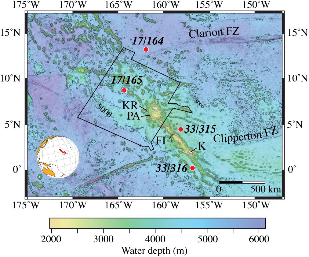
Figure 1. Overview map of the bathymetry of northern Line Islands Ridge, the area between the Clarion and Clipperton Fracture Zones. Bathymetry from GeoMapApp GMRT (Ryan et al., 2009). The solid black line outlines the area covered by this study. Red circle with black italics label indicate DSDP Leg/Site and labels “KR,” “PA,” “FI,” and “K” are locations of Kingman Reef, Palmyra Atoll, Fanning Island and Kiritimati, respectively. Black contours are 5000 m isobath.
Setting
The Line Island Ridge (Figure 1), sometimes referred to as the Line Islands chain, extends > 4000 km from the Tuamotu Islands chain in the south to the Mid Pacific Mountains in the north and consists of widely spaced islands, isolated seamounts and ridges. The main Line Island Ridge has a consistent 147°–327° (SE-NW) trend throughout its length, a characteristic that has generated widely different interpretations for its origin (Morgan, 1972; Clague and Jarrard, 1973; Winterer et al., 1973; Jackson and Schlanger, 1976; Natland, 1976; Schlanger et al., 1976; Crough and Jarrard, 1981; Larson, 1991; Davis et al., 2002; Adam and Bonneville, 2005; Pockalny et al., 2015). Some authors, i.e., Morgan (1972) and summarized by Natland (1976), interpret the Line Island Ridge as a hotspot trace that becomes younger to the south. Other authors, summarized by Davis et al. (2002), interpret the ridge as a large buildup of volcanics that was constructed during two periods (86 to 81 Ma and 73 to 68 Ma) of volcanism within a zone of extension along pre-existing areas of lithospheric weakness. Pockalny et al. (2015) suggest the Line Island Ridge originated from at least two different volcanic sources, one source formed the southern section of the ridge whereas a different source formed the northern section.
The Northern Line Island Ridge is located between the Clarion and Clipperton Fracture Zones (Figure 1) and is dominated by a broad ridge structure that stands ∼1000 m above the > 4400 m abyssal depths. The northern section of the NLIR has isolated and amalgamated volcanic peaks that rise ∼1500 m above the main ridge platform. The 1100-km-long NLIR is ∼225 km wide in the north and narrows to < 60 km in the south (out of the survey area) before the platform eventually disappears. The eastern and western margins of the NLIR platform are bordered by chains of volcanic peaks separated by ∼40 km from one another in the south and by ∼100 km in the north. The two volcanic rims rise 500 to 1000 m above the ridge platform and both Kingman Reef and Palmyra Atoll lie along the western margin of the ridge platform whereas Fanning Island and Kiritimati (Christmas Island) are situated on the eastern margin of the platform (Figure 1).
The southwest rim of the northern-most NLIR is broken into a series of nine guyots and large seamounts whose summit depths range from 848 to 1634 m below sea level and two of which rise above present-day sea level as Kingman Reef and Palmyra Atoll. The southwest rim of the platform is one limb of volcanic edifices that form the outer boundary of the NLIR and encompass a 190-km-long NW-SE basin that varies in width from 63 to 81 km. The basin contains about 1.3 km of sediments with highly reflective seismic horizons (Lyle et al., 2016).
Sedimentation on the NLIR has received only passing attention until recently. Orwig (1981) analyzed seismic-reflection profiles and speculated that the sediments of the NLIR are similar to sediments drilled by the Deep Sea Drilling Project (DSDP) in the adjacent abyssal seafloor (Figure 1). Orwig (1981) traced south- and southeast-directed pathways of calcareous turbidites and siliceous oozes from an area several hundred kilometers west of the NLIR and to the south of the area focused on here. More recently, Lynch-Stieglitz et al. (2015) and Lyle et al. (2016) described cores from the seafloor adjacent to a few guyots and ridges on the NLIR platform and demonstrated that the guyots are capped by thick pelagic carbonates. Lyle et al. (2016) provide a discussion of the lithostratigraphy and sediment thickness of the area, as well as a summary of the few seismic-reflection profiles from the NLIR and adjacent deep-ocean basins. The platform of NLIR has not been drilled to date and the nearest drilled site above the Cretaceous carbonate compensation depth is on Magellan Rise, a bathymetric high that stands ∼2500 m above the basin floor (but is ∼1500 km to the west of the NLIR) at DSDP Site 167 (Winterer et al., 1973). The lithostratigraphy at DSDP Site 167 is composed of Early Cretaceous basalt overlain by Middle Cretaceous limestone, followed by volcanic sandstone, Late Cretaceous cherty chalk and Middle Eocene and Middle Miocene foram-nanno oozes. This is essentially the same lithostratigraphic sequence recovered from DSDP Site 171 on Horizon Guyot (Schlanger et al., 1976) located ∼1500 km NNW of the NLIR.
Data Sources
This study primarily uses multibeam bathymetry and acoustic backscatter (MBES) and high-resolution subbottom seismic data collected on two UNH-CCOM/JHC cruises of RV Kilo Moana (KM1009, KM1520) and one cruise of NOAA SHIP Ron Brown (RB1601). All three of these cruises were equipped with Kongsberg Maritime 12-kHz EM122 MBES (Table 1) and Knudsen 3260 subbottom profilers. Additional multibeam data in the immediate shallow-water vicinities of Kingman Reef and Palmyra Atoll are from the Pacific Islands Benthic Habitat Mapping Center1. Older legacy multibeam data from cruises that crossed the NLIR were downloaded from https://maps.ngdc.noaa.gov/viewers/bathymetry/ and are listed in Table 1 and their locations are shown in Supplementary Figure S1. The questionable navigation of most of the older legacy data, together with early generations of MBES, renders the legacy data less reliable than the UNH-CCOM/JHC data, as was verified by cross-swath analyses against the UNH-CCOM/JHC data. The legacy cruise bathymetry were edited for obvious outliers, masked if necessary so as not to overlap with the CCOM/JHC bathymetry and, if considered reliable, were fused with the UNH-CCOM/JHC bathymetry. The final digital terrain model was gridded unprojected (in longitude-latitude) at 0.001 degrees/pixel (approximately 100 m/pixel) resolution using QPS Fledermaus and Qimera software. The background regional bathymetry for the maps and oblique images is from the GeoMapApp/GMRT v. 3.6.10 bathymetry (Ryan et al., 2009) and was gridded with a resolution of 0.017 degrees/pixel (approximately 1700 m/pixel).
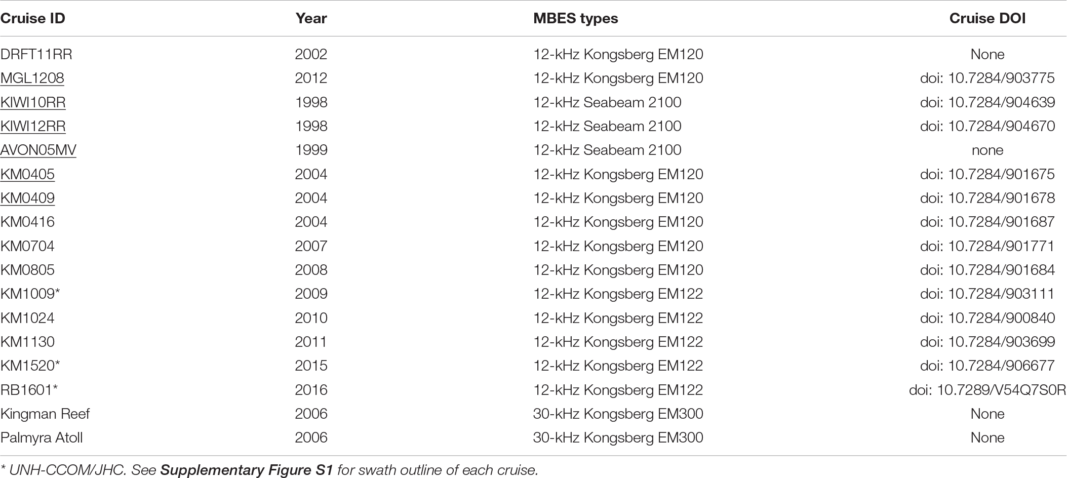
Table 1. Multibeam echosounder cruises used in the bathymetry compilation.
The high-resolution subbottom profiles collected by the Knudsen subbottom profiler on the three UNH-CCOM/JHC cruises have a bandwidth of 2.3 to 5.3 kHz centered at 3.5 kHz. The data were processed with Chesapeake Technologies SonarWiz 7.0 with a sound speed of 1500 m/s to convert travel times to water depths. Although vertical resolution for an echosounder is variable with depth, the Knudsen specifications state that the vertical resolution for this system is 1 m for depths greater than 1000 m. Adverse weather and steep bathymetry affected the quality of some of the subbottom data.
Multibeam echosounder acoustic backscatter from the three UNH-CCOM/JHC cruises were collected as calibrated co-registered time-series that represent the backscatter response to 12-kHz sound across each bathymetry beam footprint. The backscatter data were processed with QPS FMGT and reported in decibels (dB) with a range from −50 (low backscatter) to −5 dB (high backscatter). A portion of the NLIR was mapped in 1991 by the USGS EEZSCAN project that used GLORIA long-range sidescan sonar (Anonymous, 2010) that also records backscatter. However, the GLORIA system only recorded the uncalibrated backscatter response of 6.5-kHz sound from the seafloor and did not measure depth. Consequently, quantitative analyses of the bathymetry of the NLIR areas from GLORIA imagery can be highly misleading and were not used in this study.
Geomorphic Description of Channel Systems
Individual channels were identified from the MBES bathymetry as distinct linear to curvilinear relatively smooth-floored features that are found deeper than the otherwise rough seafloor (Figure 2). In addition, several channels were crossed by subbottom seismic tracklines. Analyses of the MBES data identified six distinct and separate channel systems of various lengths (53 to 542 km) and complexities. The channels on the NLIR occur over a combined drainage area of more than 60,000 km2 (Figure 3; see Supplementary Figure S2 for uninterpreted image). Drainage area is defined here as the area that contains all the tributary heads within the channel system; i.e., the submarine equivalent of a subaerial drainage area. The channels all head on the flanks of ridges, seamounts or guyots and all channels trend down-gradient rather than across-gradient. Most of the channel systems are composed of a main channel fed by first-, second-, third- and, for some, even fourth-order (à la, Strahler, 1952) dendritic tributaries and all of the main channels extend out to adjacent abyssal depths. The largest channel system trends to the northwest for the first half of its length, then gently curves northeast. Four of the channel systems trend to the west and southwest and one channel trends southeast.
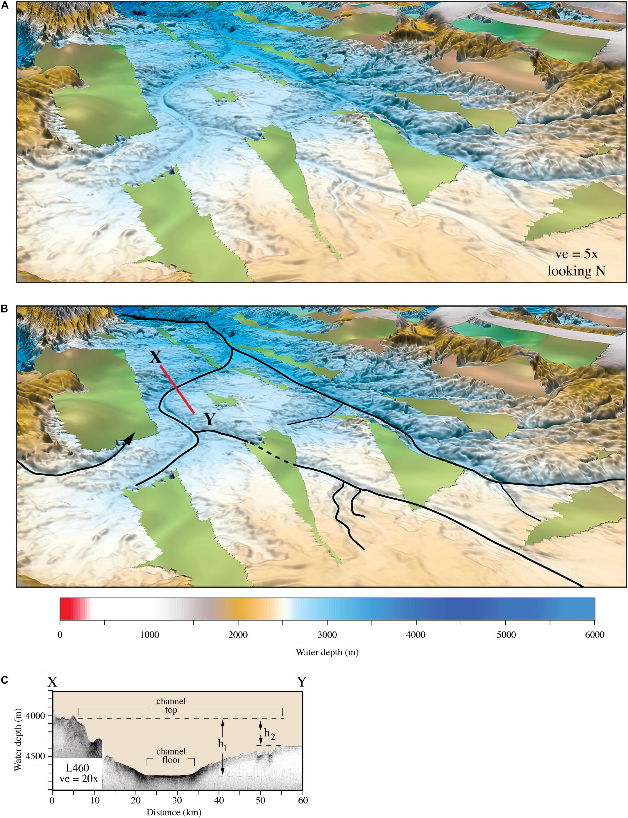
Figure 2. (A) Perspective view of a typical area of northern Line Islands Ridge that shows the smooth channel floors and linear to curvilinear nature of the channel reaches compared to the otherwise rough seafloor (only representative tributaries are shown). Locations and look direction shown as black bracket on Figure 3. Approximate dimensions of image are 105 m top to bottom and 85 km left to right. (B) Same view as (A) with channels outlined in solid black lines, dashed where assumed continuation where no MBES coverage. Red line is location of subbottom profile XY. (C) Subbottom seismic profile across a channel. Channel relief calculated as (h1-h2).
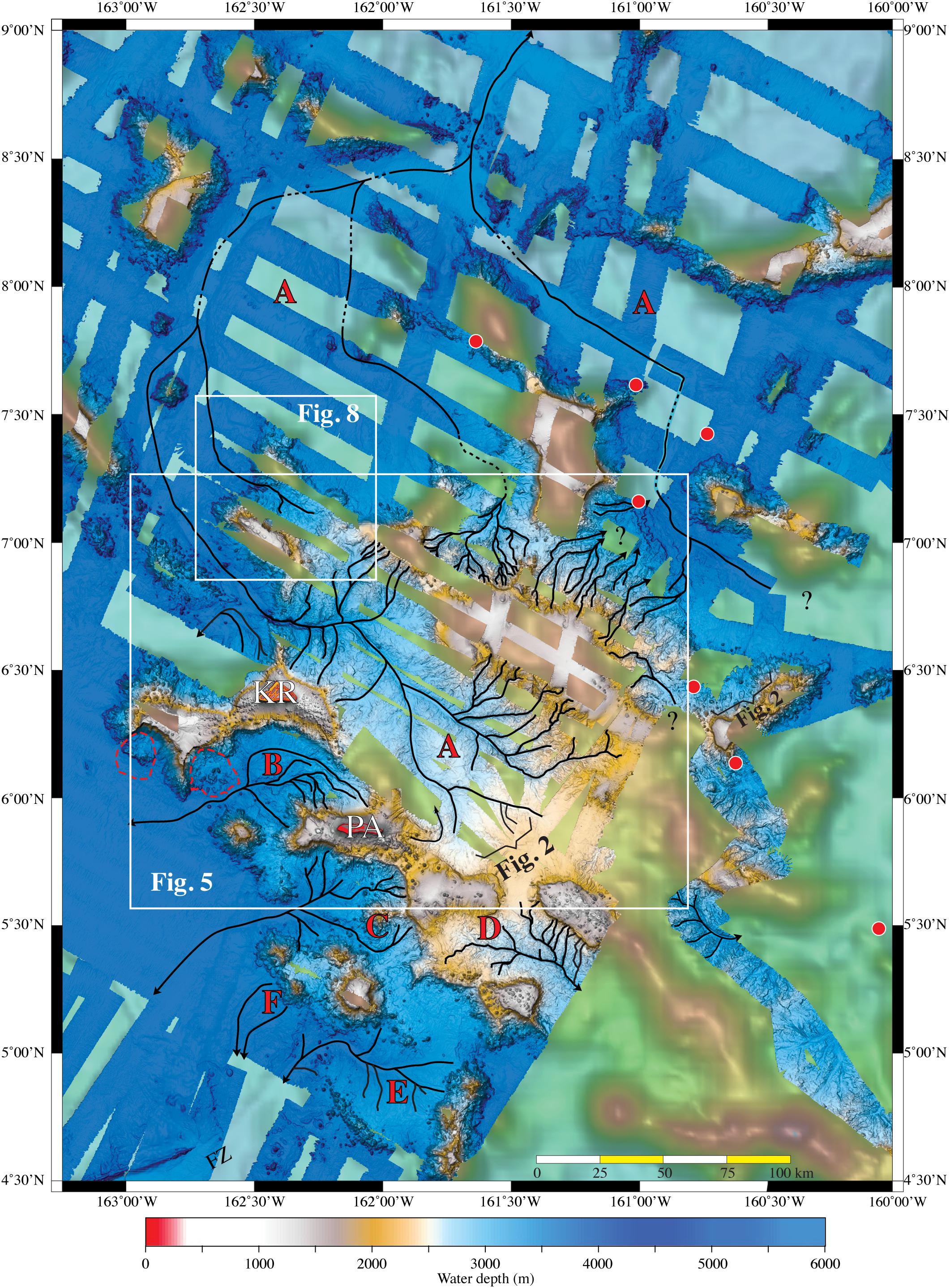
Figure 3. Map view of the multibeam bathymetry of northern Line Islands Ridge (see Supplementary Figure S2 for same view with no interpretations). Channel systems (CS) identified by red capital letters. Channels indicated in black lines. Locations of Lyle et al. (2016) cores shown as red circles. KR and PA are locations of Kingman Reef and Palmyra Atoll, respectively. Locations of Figures 5, 8 shown in white rectangles; black bracket shows view direction for Figure 2. FZ in lower left is an unnamed fracture zone.
The morphologies of the channels were traced from the MBES data and where applicable the subbottom profiles. The MBES 12-kHz acoustic backscatter from the channels has a mixed texture; some channels have high backscatter whereas others have low backscatter. The subbottom seismic profiles typically show the high impedance of the surficial sediments within the channel floors with little or no sediment penetration, although the summits of guyots and ridges do show some subbottom penetration. This was surprising because the two published reports on sediment from the NLIR both state that the surficial sediments are all pelagic carbonate oozes (Lynch-Stieglitz et al., 2015; Lyle et al., 2016) that should have low acoustic impedance that would allow significant penetration.
Measurements were made of drainage area, channel floor width, channel top width, thalweg depth and channel floor gradient at 5 km intervals down the main channels. Channel floor widths were measured as the distance across the base of the floor to the adjacent steep banks and channel relief was measured from the channel floor to the average top of the two channel banks (Figure 2C). Various schemes for subaerial channel stream power by Horton (1945), Strahler (1952), Shreve (1966, 1967), Abrahams (1984), and Kirchner (1993) were calculated but the parameters showed none of the correlations that are commonly found in studies of submarine canyons or channels on continental margins (e.g., Mitchell, 2004; Ramsey et al., 2006; Brothers et al., 2013, to name a few). Perhaps the lack of correlations is because the main channels of the NLIR do not occur on a continental margin; the NLIR channels occur in water depths deeper than 3000 m and are found not on the tops of guyots and ridges but rather in basins between the guyots and ridges on an isolated aseismic bathymetric high in the middle of the Pacific Ocean.
Major Channel Systems
Channel System A
Channel system A (CS-A) is by far the largest and most complex channel system of the NLIR with a drainage area larger than 50,500 km2) (Figure 4; see Supplementary Figure S3 for uninterpreted image). The upper half of CS-A was delineated in an area with complete MBES coverage, but the lower half is in areas with widely spaced MBES coverage although most of the tributaries and the entire main channel are well mapped with MBES. CS-A is composed of a 540-km long main channel and three major branch tributary systems, called here west branch, middle branch and east branch.
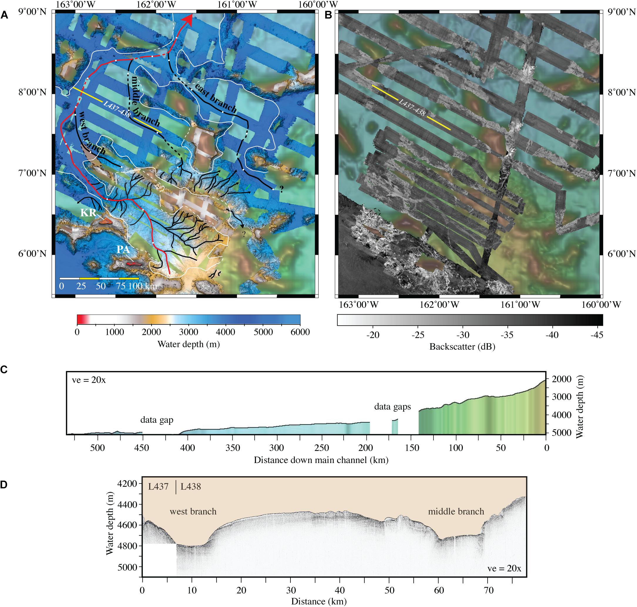
Figure 4. (A) Map view of multibeam bathymetry of channel system CS-A (see Supplementary Figure S3 for same view with no interpretations). Location of CS-A shown on Figure 3. Drainage area (see text) outlined in white, dashed line is interpreted continuation of channels in areas with no MBES coverage. Main channel is identified in red and tributary channels in black. White circles along main channel and three main branch channels are 50-km down-channel markers. Yellow line is location of subbottom seismic profile L437–438 (see Figure 4D). Locations shown of Kingman Reef (KR) and Palmyra Atoll (PA). (B) Map view of multibeam backscatter of channel system CS-A. (C) Down-channel profile along the main channel reach. (D) Subbottom seismic profile of L437 and 438 that crosses west and middle branches.
The uppermost reaches and tributaries of the main channel are located east and northeast of Palmyra Atoll and Kingman Reef and ∼30 km northeast of the western rim of a large partially enclosed basin (called “Palmyra Basin” by Lyle et al., 2016). The basin is 200 km long (NW-SE) and 70 km wide (NE-SW), encompasses water depths of 3000 to 3700 m and is perched ∼1500-m above the adjacent abyssal seafloor. The surface of the basin has a few hundred meters of rough relief but the floors of the main channel and most tributaries are smooth. The initial 1.7 km of the main channel descends to the north with a 13° gradient but quickly flattens out to a consistent 0.4° gradient. The upper reaches of the main channel are fed by first-, second- and third-order tributaries, that are formed on both the northeast and southwest flanks of a large 1400-m high ridge (Figure 5). The main channel has a generally northerly trend for the next 126 km before the channel trends to the west for 34 km and then slowly veers to the northwest for 84 km. At that point, the main channel trend changes to north-northeast for 152 km, then east for 78 km and then north-northeast 63 km before the channel is no longer resolved in the MBES bathymetry.
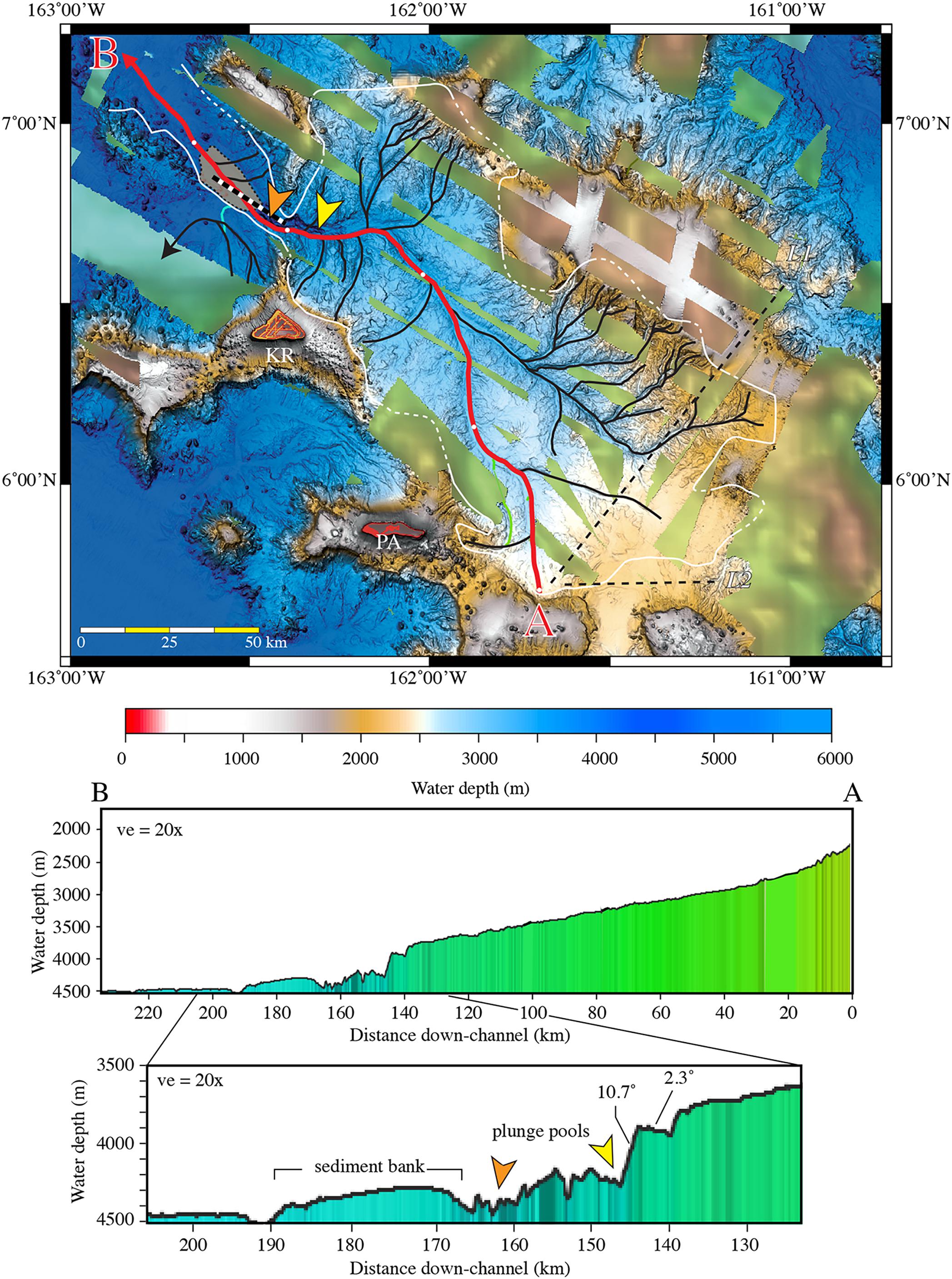
Figure 5. A Map view of multibeam bathymetry of the upper 240 km of the main channel reach of system CS-A. Upper main channel in red with white 50-km distance markers; tributaries in black. Profile A–B shows down-channel profile of the upper main channel with expanded profile below. Yellow and orange arrowheads show locations of plunge pools, light brown area is location of sediment bank. Heavy black and white dashed line is location of subbottom line L473 (see Figure 8). KR and PA are locations of Kingman Reef and Palmyra Atoll, respectively. L1 and L2 are locations of Lyle et al. (2016) high-resolution multichannel seismic profiles.
The head of the main channel of CS-A is located in ∼2400 m water depth on the east flank of a guyot southeast of Palmyra Atoll. After the initial descent of 13°, the main channel has a 1.5° gradient for 21 km before the profile flattens out to gradients of ∼ 0.4° for the next 96 km. The first 120 km of the main channel is ∼16 m to ∼100 m below the level of the basin sediments. The width of the top of the main channel reach is broad with an average of 4.15 km for the first 120 km, whereas the width of the channel floor over the same distance varies from 110 to 775 m. A first-order tributary enters the main channel from the east at 30 km down-channel followed by another first-order tributary that enters from the south 37 km father down-channel. The main channel follows a northerly course until at 82 km down-channel where a major tributary system enters the main channel from the southeast. The tributary system is composed of first-, second- and third-order tributaries that trend off the southwest flank of a guyot that forms the eastern border of the basin. The next tributary enters the main channel from the south at 94.5 km down-channel. Two tributary systems enter the main channel at 115.5 km and 118.5 km down-channel. Both of the tributary systems are composed of first- and second-order tributaries that have formed on the southwest flank of a small guyot. Up to this point, the floor of the main channel has acoustic backscatter values of −33 to −30 dB compared to the −37 to −35 dB values of the adjacent seafloor (Figure 4B). The section of the main channel from 118.5 to 131 km down-channel shows a consistent −30 dB backscatter response as it passes through a gap through a 650-m high ridge. At 142 km down-channel, the main channel enters a deeply incised deep breach in a section of a ridge that connects the north side of Kingman Reef guyot to the southeast side of an unnamed guyot to the north. The walls of the breach have slopes of 40 to 50° and the breach has incised the ridge 600 to 800 m. At a water depth of 3900 m, the channel drops 400 m with a 10.7° gradient into a 100-m-deep plunge pool (Figure 5). The channel continues to 152 km down-channel over hummocky terrain before it descends another 240 m over four back-tilted steps with gradients of 5° to 9° into a 800-m wide, 350-m long, 100-m-deep series of plunge pools (Figure 5). Unlike many submarine plunge pools described in the literature (e.g., Clague and Moore, 2002; Lee et al., 2002), a large 13-km long, 50-m-high, 1.4-km wide, high backscatter (−27 to −26 dB) sediment bank occurs just beyond the second plunge pool, similar to those identified in carbonate valleys and canyons (Mulder et al., 2018, 2019). The sediment bank represents > 9.25 km3 of sediment, based on the area of the sediment bank and the average height to the adjacent seafloor. The sediment bank has filled in a broad low valley and has surface bedforms (Figures 5, 6) with an average wave height of 3 m and wavelengths that vary from 600 to 900 m. The plunge pools occur immediately down-channel from a 1200-m-wide breach in a ridge that spans the area between the Kingman reef guyot and an unnamed guyot to the north (Figures 5A, 6). Overall, CS-A exhibits a longitudinal channel profile that appears to be broadly at equilibrium (e.g., Kneller, 2003; Figure 4C) with the notable exception of the plunge pools and associated steps (Figure 5). Bathymetric relief in the channel decreases both upstream and downstream from the point where the channel cuts through the ridge on the rim of the NLIR platform (Figure 7), which suggests the majority of the channel relief has been driven by the adjustments of the channel profile to this large-scale bathymetric barrier.
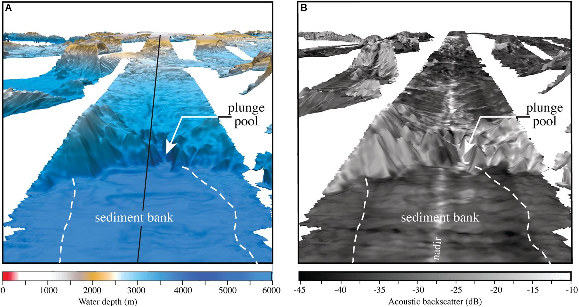
Figure 6. Perspective view of the bathymetry (A) and acoustic backscatter (B) of the plunge pool and sediment bank of channel system CS-A. Vertical exaggeration 5×. Note large difference in backscatter between the high backscatter of the flank of the NLIR escarpment and the low backscatter of the sediment bank. The sediment bank has a volume of > 9.25 km3. Black line is track of subbottom seismic line L483 shown in profile A–B (see Figure 8).
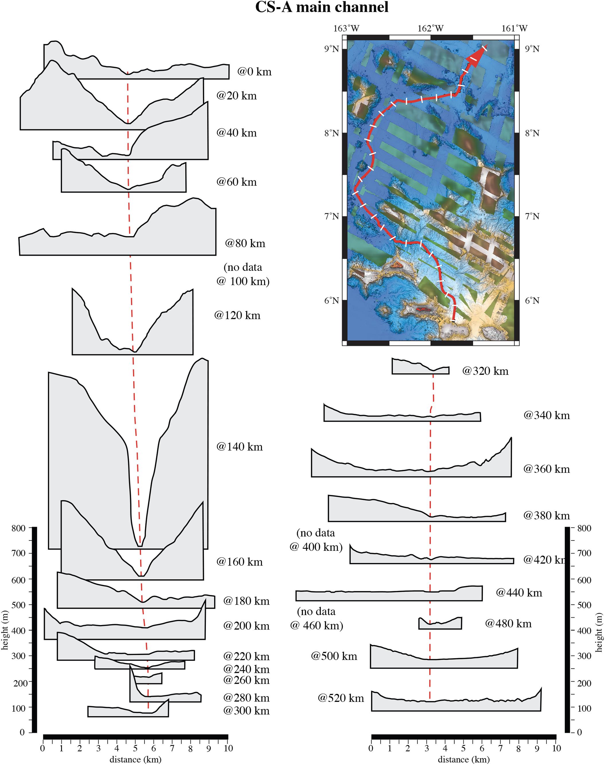
Figure 7. Stacked cross-channel profiles at 20-km intervals down the main channel of CS-A. Map inset shows locations of cross-channel profiles (white lines perpendicular to red main channel). Vertical exaggeration of profiles is 14×. Red dashed lines connect channel thalweg.
Seven small tributaries enter the main channel from either side for the next 52 km followed by a 93 km section of main channel with no tributaries that enter the main channel. At 296 km down-channel, an 84-km long second-order tributary, called west branch (Figure 4A), enters the main channel. The west branch is composed of a 34-km-long main reach and two short < 10-km-long, first-order tributaries (Figure 8). The head of the west branch is ∼90 km north of Kingman Reef in a swale between two guyots and a 3000-m-high northeast-facing ridge that separate west branch tributary from CS-A. The west branch is ∼500-m wide until a point 25-km down-channel where it abruptly narrows to less than 100 m. The tributary channel is resolved on the MBES bathymetry only for an additional 33 km down-channel. The upper reach of the west branch profile has four relatively flat steps that descend in progressively larger drops in the down-channel direction (Figure 8). Step “a” is a 6.3-km-long smooth surface with a 14° down-channel tilt. The west branch then descends 50 m with a 3° gradient to step “b,” a 6.9-km-long smooth surface tilted 12° down-channel. The west branch then descends 140 m to the almost flat (0.1°) 11-km-long smooth surface of “step c.” At this point, the channel drops 185 m to a rough 1.7-km-long surface before plunging 960 m at a 7° to 14° gradient into a 90-m deep plunge pool (Figure 8).
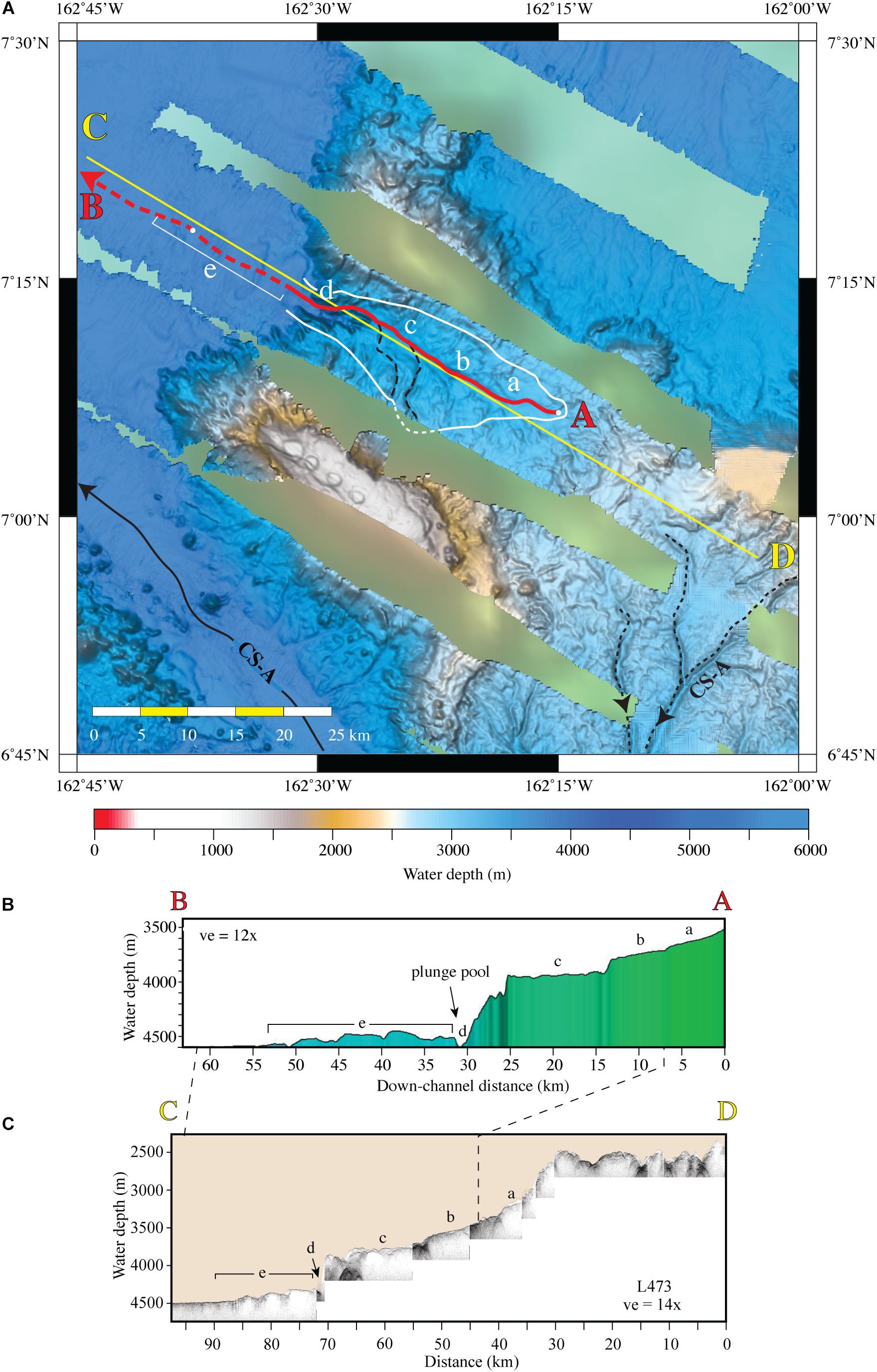
Figure 8. (A) Map view of multibeam bathymetry of the upper reach of the west branch tributary of channel system CS-A. Drainage area (see text) outlined in white (dashed in areas with no MBES data). Red line shows path of the main tributary channel; dashed red line is approximate path with white circles at 50-km down channel. Black dashed lines are adjacent tributaries of CS-A main channel and solid black line is main channel reach of CS-A. White letters a-c locate steps of the NW escarpment of the northern Line Islands Ridge in this area; letter d is location of a plunge pool and letter e is a sediment bank immediately down channel from the plunge pool (see text for discussion). (B) Down-channel profile of head of the west branch tributary. (C) Subbottom seismic line 473 that crosses the NLIR escarpment and descends to abyssal depths. Location of subbottom line C–D shown on (A).
The head of the middle branch (Figure 4A) is a series of three third-order tributaries that originate on the northeastern flank of the large ridge mentioned above. The three third-order tributaries all head in water depths of 2800 to 3000 m and occur below a local seafloor that has 50 to 100 m of relief. The tributaries all converge into a single channel at a point ∼42-km down the tributaries and, by ∼76 km from the head of the tributaries, the middle branch channel is 5 to 10 m below the local seafloor and is a 4-km wide flat channel floor at water depths of ∼4200 m. The single channel of the middle branch then traverses the next 168 km on a northwest to northerly course with only a few meters of relief until it merges with the main channel at a point 420 km down the main channel.
The east branch resembles the middle branch in many aspects, although the head of the main channel of the east branch was not mapped with MBES (Figure 4A). The heads of all but one of the east branch tributaries occur along the northeastern flank of the same ridge that the tributaries of the middle branch head on, at roughly the same range of water depths; the other is a second-order tributary that trends off the eastern flank of a guyot. The heads of the east branch tributaries are composed of first-and second-order tributaries that traverse down gradients of 1.5° to 2.5° toward the north-northeast. The MBES coverage does not image the full extent of the tributaries, but there appears to be at least two groups of tributaries. The first group is comprised of one and possibly two separate second-order tributaries; one of which has been captured at the east branch main channel and left a 50-m hanging valley. At this point, the main east branch channel floor is flat and ∼4 km wide. The full extent of the other tributary systems were not imaged with MBES so the geometries are not known. The second group is composed of at least two second-order tributaries that enter the east branch about 70 km down the east branch main channel. The second tributary system is the last one to enter the east branch for the next 190 km before it enters the main channel of CS-A.
Channel System B
The CS-B is a relatively small system with a drainage area of 2418 km2. The main channel heads on the northern flank of the Palmyra Atoll (Figures 3, 9; see Supplementary Figure S4 for uninterpreted image). The main channel is at least 115 km long but is not resolved beyond 85 km down-channel in the MBES bathymetry or the 3.5-kHz subbottom lines even though the survey lines strike NW-SE across the main channel trend on the abyssal seafloor (see Supplementary Figure S5). The main channel floor begins with a northwest trend for the first 50 km but then it has been deflected to the south in a broad 52-km curve by the lower southern insular flank of the Kingman Reef atoll. At a point 70 km down-channel, the main channel (marked “a” on Figure 9A), is joined by a 53-km long major tributary (marked “b” on Figure 9A). Seven kilometers beyond the junction, the main channel is deflected around a large landslide deposit (Figures 9A,B) that was shed off the southeastern flank of an unnamed guyot west of Kingman Reef. Outrunner blocks from the landslide are found across the channel and up against a guyot south and southeast of the channel. The main channel then trends to the west-southwest out onto the abyssal seafloor. The main channel profile has a smooth concave-up curvature, except for a section of concave-down curvature between 30 and 55 km that suggests recent sediment deposition in this zone and that the reach has not re-established an equilibrium profile (Figure 9C). The main tributary b has a persistent concave-up profile. Channel cross-sections (Supplementary Figure S6) show channel relief on the order of 50 to > 100 m from the head to the start of the abyssal seafloor, that suggests incision from the ridge platform to the seafloor that surrounds the ridge. The width of the floor of the main channel reach varies from 110 to 830 m with no correlation to water depth or down-channel distance. The mean floor width is 427 m (σ = ± 249 m) measured every 5 km down-channel. The width of the top of the channel walls varies from 1162 to 4425 m with a mean width of 2734 m (σ = ± 966 m) with a down-channel trend toward wider widths. The gradients of the channel walls vary from 1° to 55° but the variation is a function of the bathymetry adjacent to the path of the channel and is not correlated with any channel-related feature.
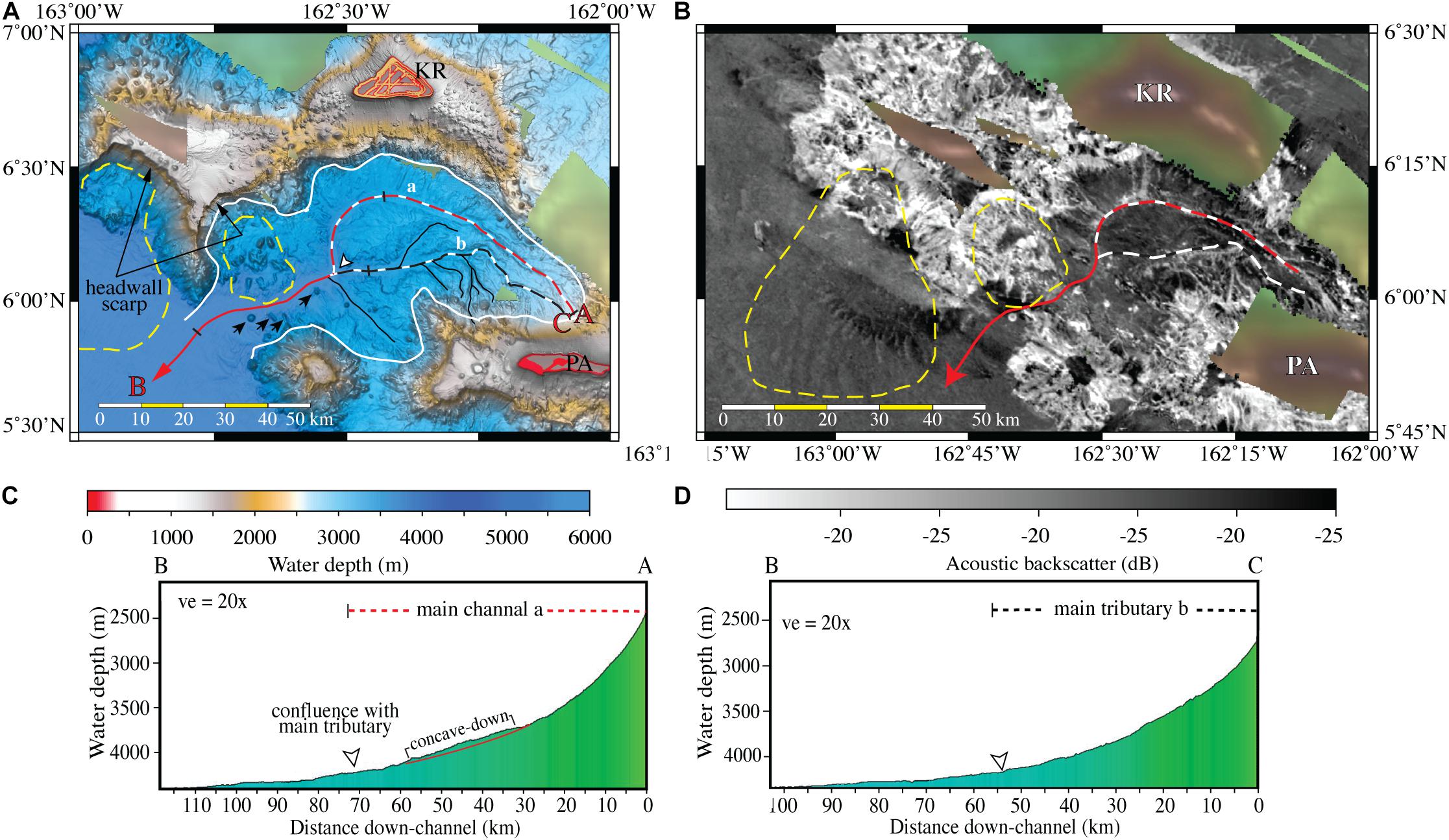
Figure 9. Map views of multibeam bathymetry (A) and acoustic backscatter (B) of channel system CS-B (see Supplementary Figure S4 for same view of bathymetry with no interpretations). Location of CS-B shown on Figure 3. Drainage area (see text) outlined in white. The upper main channel shown as a red and white dashed line labeled “a” and the lower main channel in solid red line. A major tributary is shown as a black and white dashed line labeled “b”. Tributaries are shown as solid black lines. Fifty kilometer distance markers on main channel are black lines across the channel. The down-channel profile of the main channel is labeled A–B and shown in (C). The major tributary channel “b” is shown as a black and white dashed line and the channel profile B–C is shown in (D). White arrowhead shows location of the confluence of the main channel and the major tributary channel. Minor tributary channels are shown as solid black lines. Yellow dashed lines enclose landslide deposits. Black arrows may be landslide blocks. KR is location of Kingman reef and PA is location of Palmyra Atoll.
Acoustic backscatter values of the main channel reach and several of the tributaries vary from −32 to −22 dB, compared to values of −40 to −35 dB for the adjacent seafloor (Figure 9B). CS-B has four first-order, and one second-order tributaries that feed into the main channel, some of which have high acoustic backscatter values of −22 to −27 dB whereas others have lower values of −32 to −31 dB.
Only two unequivocal landslides were identified in the NLIR and occur to the north and northwest of CS-B. The landslides are located directly downslope from large headwall scarps on the south and west flanks of a guyot about 50 km west of Kingman Reef (Figure 9). The landslides stand out as high backscatter rough surfaces that occupy reentrants into the eroded flank of the edifice. The largest of the two landslide deposits occurs on the west flank of the guyot and covers an area in excess of 1370 km2. The landslide is 10 km long in the downslope direction and 14 km wide and terminates in an abrupt 48 km high 32° slope before it continues out onto the abyssal seafloor for an additional 12 km at gradients of 2.6 to less than 0.2°. The larger landslide is best seen in the MBES backscatter and shows a pattern of linear to curvilinear ∼5-m high ridges that strike down the lower part of the deposit (Figure 9B). The ridges appear 15 km down-slope from the main mass of the landslide deposit and continue to ∼40 km down-slope on a flat seafloor. The smaller landslide covers an area of about 322 km2 and is located on the south flank of the guyot beneath another large headwall scarp. This landslide is ∼21 km long in the downslope direction and may have been even longer but it has been eroded by the main channel of CS-B. Numerous large high-backscatter blocks litter the surface of the landslide deposit and at least 4 blocks that may be outrunners occur on the south side of the main channel (Figure 9A).
Channel System C
Channel system C (CS-C) heads on the lower western flank of the same unnamed guyot that CS-A heads on (Figures 3, 10; see Supplementary Figure S7 for uninterpreted image). The main channel of CS-C is at least 130 km long although only the first 75 km are clearly resolved on the MBES bathymetry. However, the MBES backscatter clearly shows the single channel has developed into a distributary system at 80 km down channel that continues toward an unnamed fracture zone (Figure 10B).
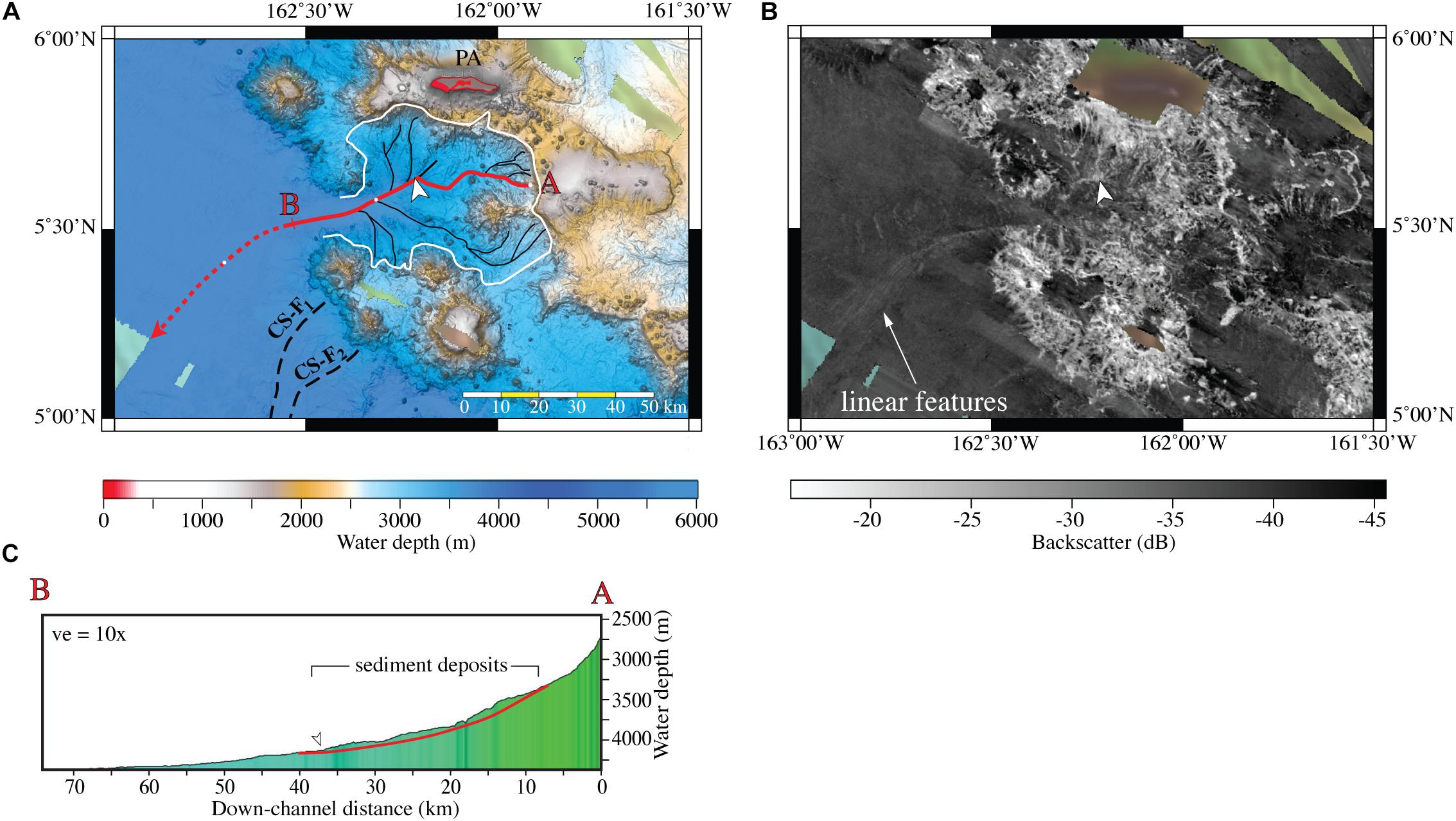
Figure 10. Map view of multibeam bathymetry (A) and acoustic backscatter (B) of channel system CS-C (see Supplementary Figure S7 for same view with no interpretations). Location of CS-C shown on Figure 3. Drainage area (see text) outlined in white, main channel in red with red dashed line showing probable path of main channel and tributaries in black. Linear features labeled in (B) are discussed in text. (C) Down channel profile of main channel A–B. White arrowhead points to location of a 62-m-high hanging valley where the upper main channel has captured a small first-order tributary. Note sediment deposits above the idealized concave-up curvature (red line in profile A–B) of the main channel.
Channel system C is fed by 12 first-order tributaries and four second-order tributaries. The channel system has a drainage area of 2110 km2. The tributaries and the main channel all head on the heavily eroded western rim of the NLIR or on the lower flanks of an isolated mass of seamounts and a guyot 32 km south-southeast of Palmyra Atoll (Figure 10A). The upper 50 km of the main channel is fed by three second-order tributaries, two of which come from the southeast and one that comes from the north. Three additional first-order tributaries feed the main channel in the first 50 km, one of which occurs where the main channel makes a sharp 60° bend to the southwest at 36 km down-channel. The main channel then follows a widening valley from the 60° bend across the basin floor and is joined by only one second-order tributary at 56 km down channel as it continues out onto the abyssal seafloor. The acoustic backscatter shows the mouth of the main channel branches out into a series of linear high-backscatter features that trend down the abyssal gradient for 55 km before they are no longer in the MBES data. The linear features have backscatter values of −35 to −34 dB whereas the adjacent seafloor has backscatter values of −40 to −38 dB. The linear features have no bathymetric relief at the resolution of the MBES, but they appear to be a linear distributary system.
The average gradient of the upper 5 km of the main reach is ∼6° but decreases to ∼2° at about 8.5 km down-channel. At this point, the floor of the main channel has a 30-km zone from 8.5 to 38.5 km down-channel that appears to be mounds of recent sediment (Figure 10C) with acoustic backscatter values of −33 dB compared to values of −37 dB in the immediate area outside the channel. The presence of these sediment bodies suggests recent sediment deposition has occurred in the upper main channel and that the reach has not re-established an equilibrium profile. From the point 56 km down-channel where the last tributary enters the main channel, although only faintly resolved in the MBES bathymetry but clearly delineated on the backscatter image (Figure 10B), trends to the southwest on a 0.1° slope toward an unnamed fracture zone. With the exception of the recent sediment mounds, the longitudinal channel profile appears to be broadly in equilibrium (Figure 10C) and is linked to high channel relief in the uppermost reaches that progressively decreases down-dip (see Supplementary Figure S6).
Channel System D
Channel system D (CS-D) is located off the southwestern rim of the NLIR in a small basin perched 2000 m above the adjacent abyssal seafloor (Figures 3, 11A; see Supplementary Figure S8 for uninterpreted image). The basin is surrounded on the north and west by two guyots and on the east by the northern nose of a 120-km long, 1800-m high ridge. The drainage area of CS-D within the MBES bathymetry exceeds 2015 km2 and could be considerably larger as suggested by the GMRT bathymetry (Figure 3). The floor of the basin has a very dense rough relief as much as 100 m but the relief lacks any clear pattern that might suggest tributaries other than those outlined. The profusion of relatively rough relief suggests the surface of the basin is composed of a hard substrate but the low backscatter values of −38 dB (Figure 11B) of the basin floor are consistent with pelagic sediment; the backscatter is very low for a hard surface (Dartnell and Gardner, 2004; Fonseca and Mayer, 2007) and sediment in the basin is not apparent from the subbottom profile (Figure 11D).
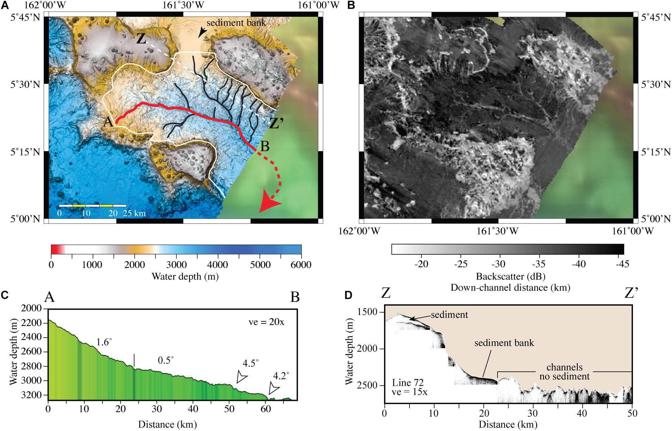
Figure 11. (A) Map view of multibeam bathymetry of channel system CS-D (see Supplementary Figure S8 for same view with no interpretations). Location of CS-D shown on Figure 3. Drainage area (see text) outlined in solid white line. The main channel is traced as a red line and tributaries in black. (B) Same area as (A) showing acoustic backscatter of CS-D. (C) Profile A-B of the down-channel distance along main channel. White arrowheads point to two significant channel descents. (D) Subbottom seismic line 172 shown in map view as white dashed line Z-Z.’
Channel system D system is composed of a main channel with first-and second-order tributaries. A few tributaries head on the guyots to the west and southwest but most head on the nose of the large ridge to the northeast (Figure 11A). The main CS-D channel is at least 70 km long and strikes northeast for 15 km and then turns on an easterly course for 40 km, then a southeast course for another 10 km before it extends beyond the MBES coverage. The GMRT bathymetry suggests the channel might descend through a gap between the ridge and the southern guyot and continue out onto the abyssal seafloor to the south (Figure 11A).
The MBES bathymetry shows that CS-D has a generally concave-up profile with a change in gradient from 1.6° for the upper 24-km of the channel to a gradient of 0.5° for the next 27 km (Figure 11C). At that point, the channel abruptly descends 55 m then continues for another 9 km before it again descends 90 m and then trends to the southeast beyond the MBES bathymetry. The channel floor is well below the level of the adjacent seafloor throughout the section covered by MBES data (see Supplementary Figure S9), perhaps a reflection of a significant bathymetric barrier downstream on the edge of the ridge.
A large sediment bank with smooth relatively high backscatter values of −36.5 to −36.0 dB (Figures 11B,D) is located astride the northern boundary of the drainage area that has buried the gap between a guyot to the west and the nose of a large ridge to the east (Figure 11A). The guyot to the west stands 650 m above the sediment bank, the northern nose of a ridge to the east stands 750 m above the sediment bank and the sediment bank is perched 170 m above the head of the closest CS-D tributary.
Channel System E
Channel system CS-E is a small system with a drainage area of 1830 km2 (Figures 3, 12; see Supplementary Figure S10 for uninterpreted image). CS-E is composed of six small (the longest is only 15 km long) first- and second-order tributaries that head on the northwestern flank of a 56-km-long NNE-SSW-trending ridge. The ridge is composed of two seamounts and a guyot that occur along the southwestern flank of the NLIR and a 35-km-long NNW-SSE-trending ridge of modest relief to the south. The head of the main CS-E channel is at 3935 m water depth at the northern base of the NNE-SSW ridge. The main channel has a smooth, almost linear descent with a gradient of 0.4 to 0.5°, even on the GMRT bathymetry, until > 80 km where the channel descends into an unnamed fracture zone (Figure 12A). The channel floor is well below the level of the adjacent seafloor in the middle of the mapped section but the relative relief decreases toward the channel head and toward the abyssal seafloor (Supplementary Figure S9), perhaps a reflection of incision because of a bathymetric barrier on the edge of the rim, even though CS-E does not appear to have reached a concave equilibrium profile (Figure 12C). The MBES acoustic backscatter of the main CS-E channel (Figure 12B) ranges from −37 to −36 dB and is especially high (−34.5 to −33.5) at a tight bend at 42 to 60 km down-channel. The subbottom profiles that cross the main channel have very little penetration and show an acoustically hard bottom (Figure 13). The main channel was not mapped with MBES in the area beyond 80 km down-channel but the channel clearly heads into the unnamed fracture zone to the southwest. The main channel is flat-floored and 3- to 4-km-wide with no well-defined thalweg. The two subbottom seismic lines that cross the main channel of CS-E show that the channel appears ∼240 m below the adjacent seafloor (Figure 13). A large levee is located on the north bank of the main channel as it exits onto the abyssal seafloor (Figure 13).
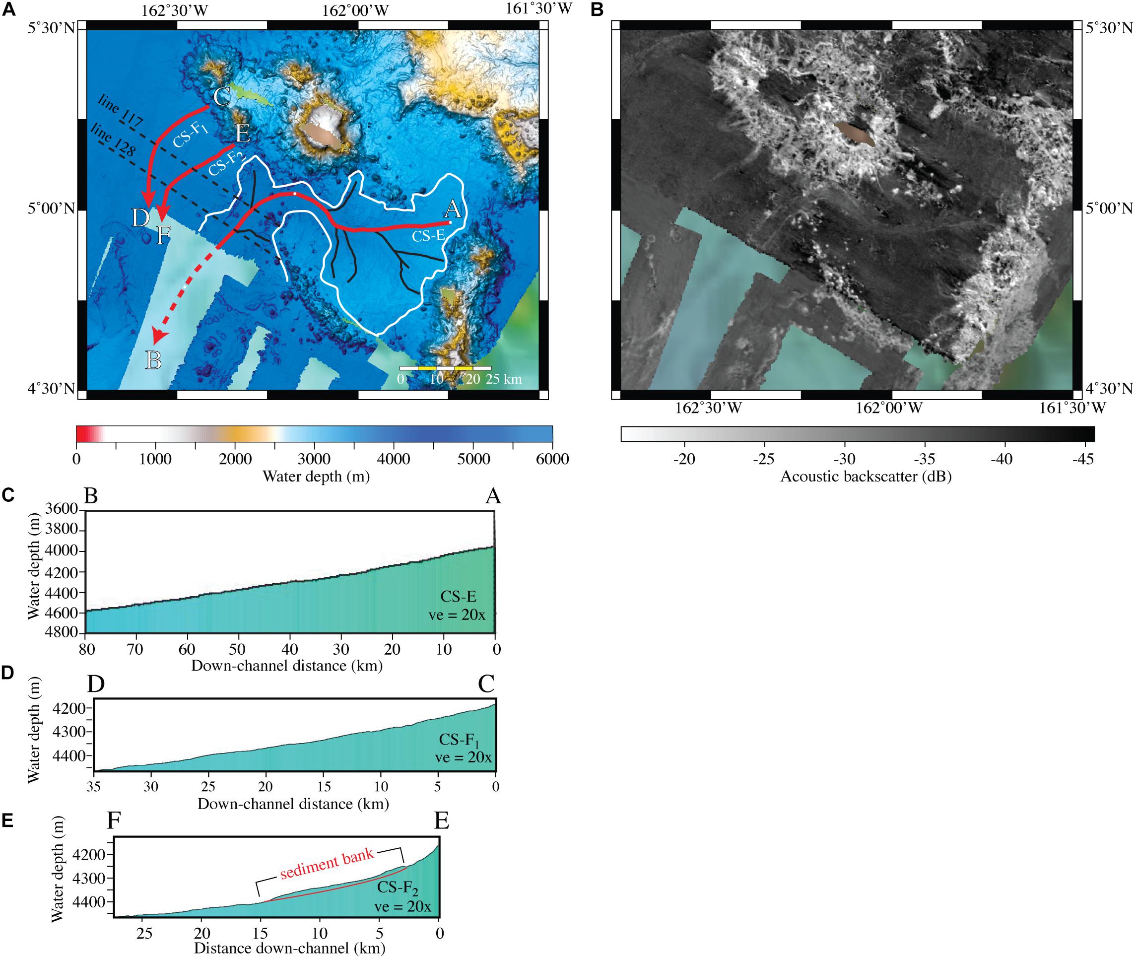
Figure 12. Map view of multibeam bathymetry (A) and acoustic backscatter (B) of channel systems CS-E and CS-F (see Supplementary Figure S10 for same view with no interpretations). Locations of CS-E and CS-F shown on Figure 3. Drainage areas (see text) of channel systems outlined in solid white line. The main channels of CS-E and CS-F are traced in bold red lines. CS-E has white 50-km distance markers. Tributaries are traced in black. Dashed bold red line is approximate southwest location CS-E main channel based on GMRT bathymetry. Dashed black lines are locations of subbottom seismic lines (see Figure 13) that cross CS-E and CS-F. (C) Down-channel profile of CS-E main channel showing the constant gradient of 0.4° to 0.5°. (D) Down-channel profile of CS-F1 and (E) down-channel profile of CS-F2. Note sediment bank in CS-F2 profile.
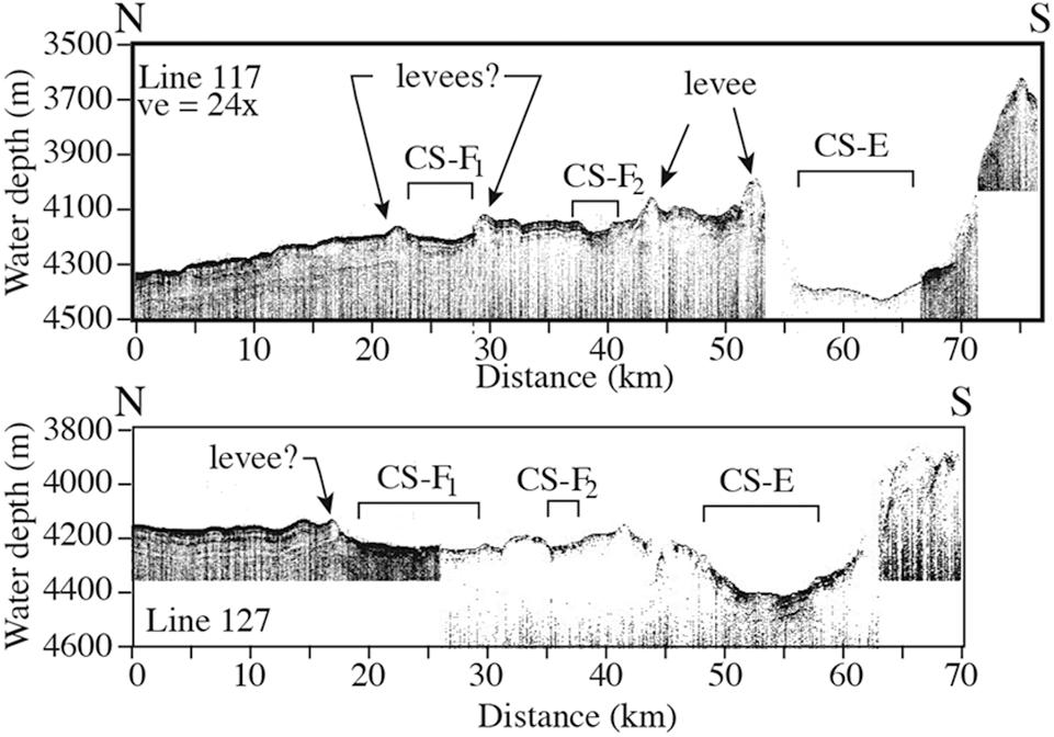
Figure 13. Two subbottom seismic profiles that cross CS-E and CS-F1 and CS-F2. Note the levee on CS-E and probable levees on CS-F1 and CS_F2. See Figure 12 for locations. Also, note the relief of CS-E below level of the abyssal basin sediments.
Channel System F
Channel system F (CS-F) is composed of two smalls channels (CS-F1 and CS-F2) with a combined drainage area of 575 km2 (Figures 3, 12; see Supplementary Figure S10 for uninterpreted image). Both channels head southwest to south from a cluster of two seamounts on the southwest flank of the NLIR. CS-F2 is separated from CS-E to the SE by a 200-m high ridge. Channels CS-F1 and CS-F2 are only 26-km and 35-km long; respectively, and have a backscatter signature of −38 to −36.5 dB compared to the −40 to −38.5 dB backscatter strength of the surrounding seafloor (Figure 12B). Both channels lead directly toward the same fracture zone as does the main channel of CS-E. The channel profiles of CS-F1 and CS-F2 are smooth with gradients of 0.5° to 0.6° (Figures 12D,E) as they approach the fracture zone but the low-resolution GMRT bathymetry cannot resolve whether or not the two channels join before they descend across the abyssal seafloor and toward the fracture zone. However, the channel profile of CS-F2 has a ∼200-m high 12-km-long section in the middle of the profile that does not follow the concave-up curve of the general equilibrium profile, suggesting the presence of a recent sediment deposit. Both channels have what appear to be 20-m high levees on their banks, although the subbottom profiles that cross the features show little internal levee structure (Figure 13). Channel relief is muted in CS-F1 throughout its course (Supplementary Figure S11) and is coupled to a long profile that is linear. CS-F2 has a long concave profile and greater channel relief in the up-channel reaches (Figure 12E) and a section of sediment deposits that suggests the channel has not regained an equilibrium profile after the sediment deposition.
Discussion
Evolution of the NLIR
The guyots of the NLIR attest to parts of the ridge having once been at sea level and have since subsided more than 1000 m. The magnitude of subsidence that the NLIR has experienced was calculated from the 28 NLIR guyots and flat-topped ridges that were mapped with MBES, excluding the islands of Kingman Reef and Palmyra Atoll (Figure 14). The present summits of the guyots range in water depths from 850 to 1872 m with a mean value of 1393 m (σ = ± 243 m). There is no trend in the guyot summit depths in either a north-south or east-west direction, which suggests the NLIR archipelago was once probably composed of large islands with a significant range in mountain heights that were eroded flat at various times as each mountain subsided to and beneath sea level, as well as low islands that quickly subsided below wave base. Today, only Kingman Reef and Palmyra Atoll remain above sea level.
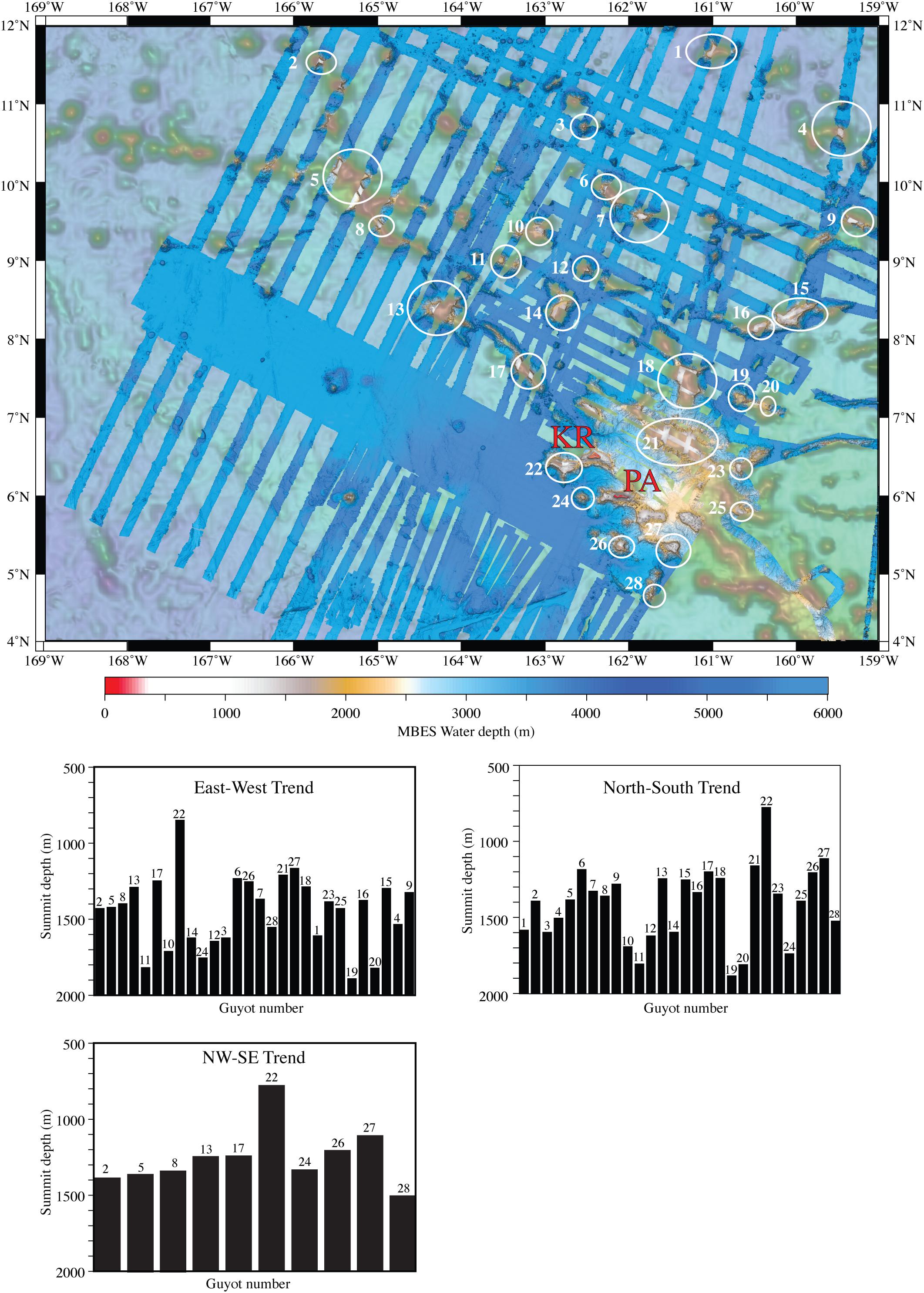
Figure 14. Map view of locations of guyots mapped from multibeam bathymetry within the northern Line Islands Ridge. KR is Kingman Reef and PA is Palmyra Atoll. Guyot numbers on map view are shown on the three histograms below map. The histograms show the guyot summit depth versus guyot in an E-W, N-W and NW-SE directions. Background bathymetry GMRT (Ryan et al., 2009).
General Sedimentation Patterns of the NLIR
General sedimentation patterns on the NLIR are difficult to determine from the scant available deep seismic data (e.g., Figure 5). It is clear from the multibeam bathymetry and subbottom seismic data that the tops of the guyots are smooth, presumably as a result of significant sediment accumulations, and lack any evidence of erosion. The interior basins and lower flanks of the NLIR have rugged bathymetry that suggests a lack of significant sediment accumulations. However, the multichannel seismic line MGL1208 E01(labeled L1 in Figure 5) shown in Lyle et al. (2016) demonstrates the reverse pattern; their Figure 4 shows a thin, although smooth sediment cover, on the summit of a guyot and thick sediment in the adjacent basin. Their line E02 (labeled L2 in Figure 5) shows a similar pattern, although the line crosses the flank of a ridge, so this might not be a meaningful comparison. The two multichannel seismic lines of Lyle et al. (2016) cross the southeastern end of the basin at the head of CS-A (Figure 5). Seismic line L2 spans the area between two guyots and crosses a large, N-S elongated smooth bathymetric high that is more than 120 m above abyssal depths to the south and 60 m above basin depths to the north. Additionally, the MBES coverage shows the summits of the guyots have mottled backscatter textures with patches of high (−18 dB) as well as low (−37 dB) backscatter (Figures 15A,B). The backscatter response is much higher than the relatively consistent −42 to −38 dB backscatter for the basin areas of the NLIR and the abyssal seafloor adjacent to the NLIR area (Figures 15C,D). This suggests that fine-grained sediments were likely transported from the guyots. Such export of fine-grained sediment from the guyots fits with observations of extensive sedimentation in the apron around the NILR (Lyle et al., 2016) and the recovery of extensive sections of pelagic calcareous turbidites and pelagic nannofossil oozes at DSDP site 315 (Figure 1) to the east of the ridge (DSDP Leg 33 Shipboard Scientific Party, 1976).
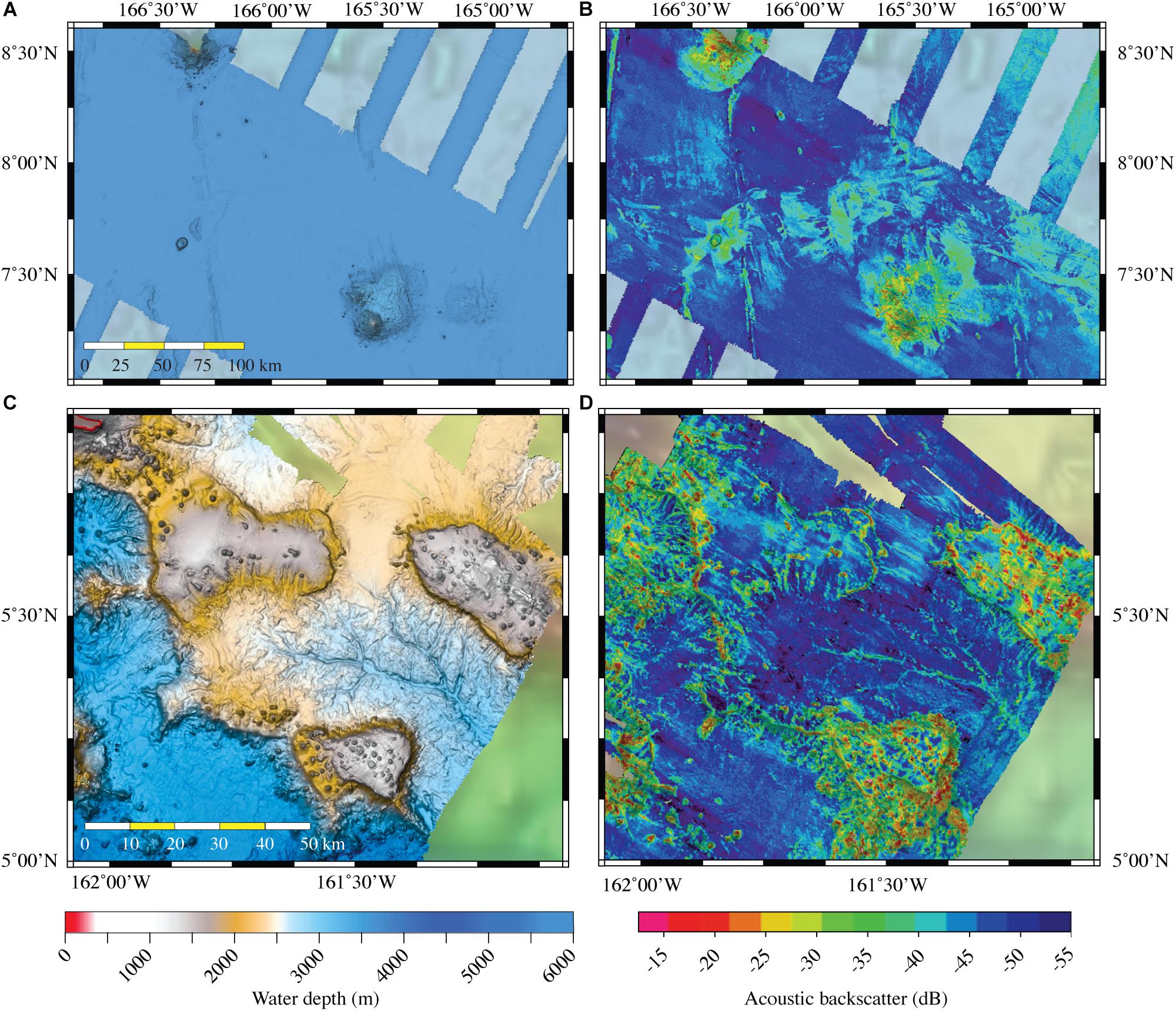
Figure 15. (A) Map view of the bathymetry of a typical abyssal seamount immediately west of the NLIR and (B) same area showing acoustic backscatter of the seamount and adjacent abyssal seafloor. (C) Map view of the bathymetry of typical guyots on the NLIR and (D) same area showing acoustic backscatter of the guyots and adjacent seafloor. Locations of abyssal seamounts immediately west of Kingman Reef and Palmyra Atoll; location of guyots is area of CS-D southwest of Palmyra Atoll.
Active Submarine Channels
Many of the subbottom seismic profiles collected on the three UNH multibeam cruises cross channels. All of the channel floors have a high acoustic response with little or no penetration and have high MBES backscatter compared to the adjacent seafloor. All of the channel floors have little or no pelagic drape, even including channel heads in water depths less than 2300 m. However, sediment drape is apparent in some of the non-channel areas in subbottom profiles down to depths as deep as 4975 m. Lyle et al. (2016) state the carbonate compensation zone (CCD) in the NLIR area is about 4800 m deep. Little or no pelagic drape even in channel floors as shallow as 2300 m, together with the high backscatter of the channel floors, suggests active sediment transport has kept the channel floors swept clean of pelagic sediment, rather than carbonate dissolution. An alternative suggestion is that the presence of unfilled plunge pools and large sediment banks immediately down-channel from the plunge pool along the main reach of CS-A and the west branch tributary of CS-A suggest that this channel system was recently active in transporting sediments toward the abyssal seafloor. If the plunge pools and associated sediment banks were features inherited from Cretaceous or Early Paleogene processes, then they should be buried by pelagic sedimentation. The plunge pools of CS-A presumably would be the result of dense turbidity currents that cascaded off the 600 to 700 m > 20° escarpment to the < 1° seafloor of the abyssal depths and excavated the base by hydraulic jumps or the impact of dense turbidity currents (Mulder and Alexander, 2001; Lee et al., 2002; Mulder et al., 2018, 2019). The suggestion of recently active channels is in agreement with earlier ideas based on higher backscatter intensities of the head reaches of some of the channels (Lynch-Stieglitz et al., 2015; Lyle et al., 2016). Here we document how extensive these channel systems are, provide a wider range of criteria for the identification of recent channel activity and demonstrate that the channels have been recently active throughout their courses. The evidence cited above suggests the channel systems may have been active in the late Neogene or even younger periods.
A key question is what processes controlled the formation and maintenance of these large channel systems. Lynch-Stieglitz et al. (2015) describe the sediments of the ridge as mostly winnowed foraminifera sands, convincing evidence that submarine currents have reworked the sediments of the area. However, a 570 cm core from the northeastern rim of the NLIR has a remarkably consistent interval sedimentation rate of 1.3 cm/kyr for the past 424 ka based on eight marine isotope boundary intervals. Another core, 204 cm long, has a consistent interval sedimentation rate of 2.4 cm/kyr for the past 87 ka based on five marine isotope boundary intervals (Lynch-Stieglitz et al., 2015). These sedimentation rates are not too different from the Middle Miocene to Recent pelagic sedimentation rates of 1.56 to 2.25 cm/kyr found on Horizon Guyot, 1500 km NNW of the NLIR (Winterer, 1976), and both locations have evidence of current winnowing. Lyle et al. (2016) state that estimated maximum bottom current speeds at the Line Islands Ridge are 20 to 25 cm/s and at some areas the speeds are as fast as 40 cm/s, based on a HYCOM model. These current speeds are likely sufficient to winnow nannofossils from the pelagic sediment, and at least some planktonic foraminifers (Miller and Komar, 1977; Yordanova and Hohenegger, 2007). The mottled backscatter textures on the guyots further suggests that there may have been winnowing and removal of the finest-grained components. These observations suggest that the extensive channel systems may have captured and transported only fine-grained winnowed material such as nannofossils and foraminifers from the guyots, perhaps intermixed with pelagic sediment, within the bathymetric lows between the guyots and ridges. Although no samples have yet been collected from the channels to verify this speculation, there is direct evidence for pelagic calcareous turbidites in DSDP site 315 (DSDP Leg 33 Shipboard Scientific Party, 1976).
An alternative is that these channels have transported volcaniclastic material from failures of the flanks of the guyots and subsequent transformation of these materials to turbidity currents. Relatively recent erosion is evident from the MBES bathymetry data as well as from the sediment studies of Lynch-Stieglitz et al. (2015) and Lyle et al. (2016). The flanks of the guyots and ridges show some landslide headwall scarps (also noted by Lyle et al., 2016) in a few areas, but especially the southeastern and southwestern flanks of the guyot due west of Kingman Reef where large fields of landslide debris have been deposited on the lower flanks of the guyots and seamounts and on the adjacent abyssal seafloor. However, there is a surprising lack of landslide debris at the bases of most of the guyots and ridges, no areas of high backscatter that should reflect the roughness of a debris deposit, as well as no obvious landslide debris mapped within any of the channel systems. Furthermore, none of the sediment cores described by Lynch-Stieglitz et al. (2015) contain volcaniclastic material, with Lyle et al. (2016, p. 202) summarizing that NLIR “sediments are essentially 100% carbonates.” This observation suggests that much of the relatively recent erosion is of materials that are easily transported, such as carbonate material that drapes the guyots. Similar observations have been made of failure and subsequent channelized transport of draped carbonate material from the flanks of the Exuma Valley in the Bahamas (Mulder et al., 2019).
Given the evidence of extensive production of pelagic carbonates in the NLIR, the winnowing of the finer-grained components, the possible direct input of carbonate materials from slope failures on the flanks of the guyots, and evidence from DSDP site 315 for calcareous pelagic turbidites, then these channels were most likely formed and are maintained by calcareous turbidity currents.
The Longest Calciclastic Submarine Channel Yet Mapped
Calciclastic subaqueous channels are rare in comparison to siliciclastic submarine channels, in both the modern (e.g., Mulder et al., 2014, 2019), and the ancient (Payros and Pujalte, 2008). Modern examples of calciclastic systems include the ∼250-km-long Exuma (Bahamas) valley, canyon, and submarine fan system (Mulder et al., 2019), the 135-km-long Great Abaco Canyon (Bahamas) (Mulder et al., 2018) and the 80-km-long Bass Canyon (Australia) (Mitchell et al., 2007). Calcareous nannoplankton flows from the Cruiser, Hyeres and Meteor Seamounts traverse > 200 km through the Cruiser Fracture Zone and onto the Madeira Abyssal Plain (Weaver et al., 1992; Lebreiro et al., 1998; Alibés et al., 1999), although it is unknown whether the nannoplankton flows develop a true channel within the fracture zone. Similarly, total transport distances of calcareous turbidity currents in ancient calciclastic submarine fan systems are less than 120 km long (Payros and Pujalte, 2008). Yet, the CS-A channel presented herein is ∼540 km long, so more than twice the length of any previously described calciclastic submarine channel, and this does not include any submarine fan component (see Section 5.6).
So why is the total transport distance of CS-A so great? Firstly, total relief is ∼3 km that allows slope angles to be maintained and, secondly, bathymetric confinement by the guyots and basins within the NLIR is provided for a considerable portion of the total channel distance. Externally imposed bathymetric confinement is important in other long runout calciclastic systems (Weaver et al., 1992; Mulder et al., 2018, 2019). Lastly, the probable very fine-grained nature of the calcareous material at the NLIR should also aid long-distance transport. Although Lyle et al. (2016) report ∼50% of the sediments are < 64 μm, much of the winnowed material is more likely much finer than this; calcareous nannoplankton are typically defined as 2 to 20 μm (Omori and Ikeda, 1992) and, at DSDP Site 315, 61% to 75% of the sediment is < 3.9 μm (Bode, 1976). Furthermore, planktonic foraminifera that appear to be dominant at the NLIR have settling velocities ∼5.8 times slower than an equivalently sized quartz grain (Berger and Piper, 1972); thus the foraminifera are comparable to grains with diameters 2.4 times smaller than their actual sizes (Berger and Piper, 1972). Collectively, these may be close to optimal conditions for a calciclastic turbidite system. Although large siliciclastic submarine channels are known to have transport distances of up to 3800 km (Klaucke et al., 1998a), these channels are typically fed by direct input from rivers or glacial outburst floods (Wynn et al., 2007; Piper and Normark, 2009), in contrast to the flows that must operate in the NLIR channels.
Given the pronounced channel relief, particularly where channels incise the ridge (relief as high as 600 to 800 m), sediment-laden turbidity currents would have to have been generated that were dense enough to erode and move the eroded sediment out into abyssal depths. Typical bulk concentrations for siliciclastic turbidity currents are estimated at between 0.2 and 2.5% (Pirmez and Imran, 2003; Konsoer et al., 2013), although flows are often highly stratified so that basal concentrations may be considerably higher (Peakall et al., 2000; Peakall and Sumner, 2015). Consequently, bulk concentrations do not need to be particularly high for erosion and substantial sediment transport.
The Rarity of Channel-Levees
The scarcity of levees on the NLIR MBES bathymetry is puzzling but, given the extensive relief of the channels, the flows may have been fully contained within the bathymetry for much of the flow paths. However, levees are observed where flows emerge into more unconfined settings (Figure 13). The largest of these levees has an external relief of ∼150 m, not large by siliciclastic systems where levees can be several hundreds of meters high (e.g., Von Rad and Tahir, 1997; Klaucke et al., 1998b; Babonneau et al., 2002). This said, levees are rare in carbonate channels in the modern (Mulder et al., 2014, 2018, 2019), although there is evidence for calciclastic levees in the past in the LNIR (Lyle et al., 2016) and in ancient systems (Payros and Pujalte, 2008).
The Absence of Fan Deposits at Channel Terminations
There is little evidence from the MBES bathymetry or subbottom data to suggest any fans at the mouths of the main channels as they reach the surrounding basins. If the channel systems carried a sediment load vigorous and dense enough to incise the edges of the ridge and maintain the channels, then where are all the sediments going once they were transported out onto the adjacent basins? There has been a considerable amount of erosion considering the volume of all the channels. It seems improbable that there is not any fan expression in the bathymetry. However, the distal reaches of the channels are at considerable depth, in the case of the longest channel CS-A, the termination is at 5000 m, deeper than the present depth of the CCD (∼4800 m; Berger et al., 1976; Lyle et al., 2016). Other channel terminations vary between ∼3200 and 4700 m, somewhat shallower than the CCD although within the lysocline. So it may be the case that there is dissolution of sediment that is deposited at channel terminations. That said, the transported material may be so fine, that it essentially acts like the mud fraction does in siliciclastic systems, which can in some cases lead to long channels (> 700 km) without a submarine fan, as the sediment continues toward an abyssal plain (Stevenson et al., 2013). The high-backscatter linear features (Figure 10B) that extend out from the mouth of CS-C may be evidence of a small fan but the lack of any bathymetric relief across the features makes any interpretation highly speculative.
Age of Channel Initiation
One hypothesis for the origin of the channel systems is that the channels developed in the Cretaceous and Paleogene by erosion of the flanks of mountains (now guyots) and ridges when the NLIR was a large mountainous archipelago. This hypothesis is supported by the observation that the heads of all the first-, second- and third-order tributaries are found on the flanks of guyots and ridges and only one first-order tributary on CS-D heads within a bathymetric low between the guyots and ridges. However, this hypothesis raises the question of why the channel systems have not been buried by millions of years of both volcaniclastic sediments from the volcanic basement as well as millions of years of pelagic sedimentation? Although early carbonate pelagic sedimentation was reduced during the Late Cretaceous and Early Paleogene because of a shallow CCD (Pälike et al., 2012), the NLIR passed beneath the high productivity equatorial zone in the mid Paleogene and should have accumulated a blanket of pelagic sediments at least several hundred meters thick. The present surface of the NLIR is at least a kilometer above the CCD. Consequently, it seems reasonable to conclude that a thick sediment blanket should have buried any relict channel system on the NLIR. A second hypothesis for the origin of the NLIR channel systems is that the channels formed recently, perhaps in the late Neogene or even later, when the summit of the NLIR had subsided close to its present water depths. Lyle et al. (2016); their Figures 4, 8) show a seismic record across the head of a major tributary of CS-B (dashed thin black line on (Figure 5) that documents a mostly acoustically transparent sediment sequence at least 600 m thick, containing evidence for extensive sedimentation (hundreds of meters) below the present seafloor channels, and for older buried channels. This indicates that the present seafloor channels were not formed at the start of sedimentation within the NLIR, but rather were formed much later after extensive sedimentation. The lack of pelagic drape over the channels but seen in some of the overbank areas suggests that down-channel processes have kept the channels clear of pelagic drape.
Conclusion
Two hypotheses are presented to explain the presence of extensive, dendritic channel systems on the NLIR, following the multiple working hypotheses methodology championed by Chamberlain (1965). The first hypothesis suggests the channels were created when the NLIR was an archipelago with numerous subaerial volcanoes and low-lying atolls. It seems reasonable that a large high-relief archipelago could be the site of extensive subaerial and shallow submarine channel systems. However, two points make this hypothesis dubious: (1) the NLIR was created 86 to 68 Ma ago and subsided at least 1500 m below sea level by the mid Paleogene; consequently, the platform of the NLIR should be buried by several hundred meters of pelagic sediment and (2) the channel systems would be relict features and would have to have aggraded through the sediment sections to the present surface of the NLIR. The aggraded channel-floor sequences would have left a record in the sediment sections, but the channels have no high-amplitude reflectors in the multichannel seismic profiles of Lyle et al. (2016). The second hypothesis is that the channels were formed relatively recently and may still be active. Although the presence of plunge pools leads us to favor this hypothesis, this second hypothesis also presents some puzzling aspects: (1) is the minor evidence of landslides and erosion seen on the flanks of guyots and seamounts enough to be sources of the dense sediment-laden erosional flows needed to create the large channel systems in > 1500 m water depths and (2) is the absence of sediment fans on the proximal abyssal seafloor at the mouths of the main channels simply because the predominant sediment that formed and maintained the channels being calciclastic rather than siliciclastic in composition? Although the second hypothesis seems geologically more reasonable than the first one, the puzzling aspects of the two hypotheses leaves us in a quandary of which one to favor. It is difficult to reconcile the observations from the MBES and seismic data with the two proposed hypotheses. Perhaps we do not have the appropriate data (dated cores from the floors of the channels?) to answer the question of the origin of the channel systems.
The only observations so far that can be confidently stated about the channel systems are:
(1) The channel systems of the platform summit of the NLIR are extensive, well developed with smooth channel floors well below the otherwise relatively rough bathymetry of the adjacent seafloor.
(2) The channel systems all head as dendritic tributaries on the flanks of bathymetric highs.
(3) The NLIR has been dated as 86 to 68 Ma old but the channel systems are not buried by millions of years of pelagic sedimentation.
(4) The main channel reaches are all relatively straight or with broad curvatures but with some abrupt nearly 90° turns. No meander bends were found, not even on flat seafloor.
(5) Only the two smallest channels have levees imaged in the subbottom seismic profiles.
(6) High-resolution subbottom profiles, as well as high MBES backscatter, show the channels have high reflectivity compared to what is expected from pelagic sediment. The adjacent seafloor has comparatively low reflectivity.
(7) Parts of the NLIR were once above sea level, attested to by the presence of guyots.
(8) The NLIR has subsided more than 1000 m below sea level.
(9) There are only rare occurrences of slope failures and landslides throughout the NLIR.
(10) The presence of plunge pools of two channel systems suggests relatively recent and at least episodic strong, erosional sediment-laden down-channel flows.
(11) The relative youth of channel activity, demonstrated by the lack of pelagic drape over the channels yet found in the overbank areas, suggests down-channel processes have kept the channels from being buried.
(12) No evidence of fans was found where the main channels exit onto the surrounding basin floors. However, linear high-backscatter features extend out from the mouth of channel CS-C but they have no bathymetric expression at the resolution of the MBES.
Data Availability Statement
The raw data used in this study are all publicly available at the NOAA NCEI (National Centers for Environmental Information) website at: https://maps.ngdc.noaa.gov/viewers/bathymetry.
Author Contributions
JG: planned all three of the UNH cruises, was Chief Scientist of KM1009, processed KM1009 MBES and subbottom data at sea, reprocessed MBES bathymetry and backscatter and subbottom data from the three UNH cruises (KM1009, KM1520, and RB1601), downloaded and processed raw MBES bathymetry from legacy data from the NCEI multibeam data website, merged all processed bathymetry into a single DTM and backscatter mosaic, interpreted the MBES and subbottom data and wrote the manuscript. JP: reviewed several versions of the manuscript and added a significant portion of the interpretations, especially on the importance of the erosion of nannofossils in maintaining the channels. AA: Chief Scientist of UNH cruise RB1601, initial processing of the MBES and subbottom data at sea and added to the interpretations of the channel systems. BC: Chief Scientist of UNH cruise KM1520, initial processing of MBES and subbottom data at sea.
Conflict of Interest
The authors declare that the research was conducted in the absence of any commercial or financial relationships that could be construed as a potential conflict of interest.
Acknowledgments
This work would not have been possible without the exemplary support of the officers and crew of the R.V. Kilo Moana (KM1009 and KM1520) and NOAA Ship Ron Brown (RB1601) and especially the support of the onboard technicians. Larry Mayer, Mitch Lyle, and five journal reviewers all provided constructive and thought-provoking reviews of earlier drafts of the manuscript that significantly improved the final version. The multibeam echosounder data were collected to support the bathymetry mapping for the U.S. Extended Continental Shelf efforts conducted by the University of New Hampshire’s Center for Coastal and Ocean Mapping/Joint Hydrographic Center. The data collection and analyses were funded under NOAA grants NA15NOS4000200 and NA10NOS4000073. The U.S. Extended Continental Shelf bathymetry effort is unique among maritime nations in that the collected data are publicly available soon after completion of each cruise for use by the scientific and industrial communities and the public.
Supplementary Material
The Supplementary Material for this article can be found online at: https://www.frontiersin.org/articles/10.3389/feart.2020.00087/full#supplementary-material
FIGURE S1 | Map of multibeam cruise data used to construct the bathymetry digital terrain model and backscatter image.
FIGURE S2 | All of the channels of the NLIR shown on Figure 3 with no interpretation of channels. Channel drainage areas are outlined in white lines, dashed where inferred, and are labeled in white capital letters.
FIGURE S3 | Map view of multibeam bathymetry of channel system CS-A shown in Figure 4A with no interpretation.
FIGURE S4 | Map views of multibeam bathymetry of channel system CS-B shown in Figure 9A with no interpretation.
FIGURE S5 | Subbottom seismic survey lines across channel systems CS-B and CS-C.
FIGURE S6 | (A) Locations of 5-km cross-channel profiles of main channel of CS-B and CS-C. (B) Cross-channel profiles of main channel of CS-B and CS-C.
FIGURE S7 | Map view of multibeam bathymetry of channel system CS-C shown in Figure 10A with no interpretation.
FIGURE S8 | Map view of multibeam bathymetry of channel system CS-D shown in Figure 11A with no interpretation.
FIGURE S9 | (A) Locations of 5-km cross-channel profiles of main channel of CS-D and CS-E. (B) Cross-channel profiles of main channel of CS-D and CS-E.
FIGURE S10 | Map view of multibeam bathymetry of channel systems CS-E and CS-F shown in Figure 12A with no interpretations.
FIGURE S11 | (A) Locations of 5-km cross-channel profiles of main channel of CS-F1 and CS-F2. (B) Cross-channel profiles of main channel of CS-F1 and CS-F2.
Footnotes
References
Abrahams, A. D. (1984). Channel networks: a geomorphological perspective. Water Resour. Res. 20, 161–168.
Adam, C., and Bonneville, A. (2005). Extent of the South Pacific superswell. J. Geophys. Res. 110:B09408. doi: 10.1029/2004JB003465
Alibés, B., Rothwell, R. G., Canals, M., Weaver, P. P. E., and Alonso, B. (1999). Determination of sediment volumes, accumulation rates and turbidite emplacement frequencies on the Madeira Abyssal Plain (NE Atlantic): a correlation between seismic and borehole data. Mar. Geol. 160, 225–250. doi: 10.1016/s0025-3227(99)00026-2
Anonymous (2010). Kingman Reef and Palmyra Atoll field Activities. U.S. Geological Survey Open-File Report 2010–1332. Reston: USGS.
Babonneau, N., Savoye, B., Cremer, M., and Klein, B. (2002). Morphology and architecture of the present canyon and channel system of the Zaire deep-sea fan. Mar. Pet. Geol. 9, 445–467. doi: 10.1016/s0264-8172(02)00009-0
Berger, W. H., Adelseck, C. G., and Mayer, L. A. (1976). Distribution of carbonate in surface sediments of the Pacific Ocean. J. Geophys. Res. 81, 2617–2627. doi: 10.1038/s41598-018-26598-9
Berger, W. H., and Piper, D. J. W. (1972). Planktonic foraminifera: Differential settling, dissolution, and redopisition. Limnol. Oceanogr. 17, 275–287. doi: 10.4319/lo.1972.17.2.0275
Bode, G. W. (1976). “Grain size analyses, Leg 33,” in Initial Reports of the Deep Sea Drilling Project. eds L. D. Kulm and R. W. von Huene (Washington, DC: US Government Printing Office), 1061–1067.
Brothers, D. S., ten Brink, U. S., Andrews, B. D., Chaytor, J. D., and Twichell, D. C. (2013). Geomorphic process fingerprints in submarine canons. Mar. Geol. 337, 53–66. doi: 10.1016/j.margeo.2013.01.005
Chaytor, J. D., ten Brink, U. S., Solow, A. R., and Andrews, B. D. (2009). Size distribution of submarine landslides along the U.S. Atlantic margin. Mar. Geol. 264, 16–27. doi: 10.1016/j.margeo.2008.08.007
Clague, D. A., and Jarrard, R. D. (1973). Tertiary pacific plate motion deduced from the hawaiian emperor Chain. Geol. Soc. Am. Bull. 43, 641–656.
Clague, D. A., and Moore, J. G. (2002). The proximal part of the giant submarine Wailau landslide, Molokai, Hawaii. J. Volcanol. Geotherm. Res. 113, 259–287. doi: 10.1016/s0377-0273(01)00261-x
Dartnell, P., and Gardner, J. V. (2004). Predicting seafloor facies from multibeam bathymetry and backscatter data. Photogram. Eng. Remote Sens. 70, 1081–1091. doi: 10.14358/pers.70.9.1081
Davis, A. S., Grey, L. B., Clague, D. A., and Hein, J. R. (2002). The Line Islands revisited: New 40Ar/39Ar geochronologic evidence for episodes of volcanism due to lithospheric extension. Geochem. Geophys. Geosyst. 3:28.
DSDP Leg 33 Shipboard Scientific Party (1976). Site 315. In: Initial Reports of the Deep Sea Drilling Project. 33, 37–104.
Fonseca, L., and Mayer, L. (2007). Remote estimation of surficial seafloor properties through the application of angular range analysis to multibeam sonar data. Mar. Geophys. Res. 28, 119–126. doi: 10.1007/s11001-007-9019-4
Galéron, J., Menot, L., Renaud, N., Crassous, P., Khripounoff, A., Treignier, C., et al. (2009). Spatial and temporal patterns of benthic macrofaunal communities on the deep continental margin in the Gulf of Guinea. Deep Sea Res. II 56, 2299–2312. doi: 10.1016/j.dsr2.2009.04.011
Gardner, J. V. (2010). The West mariana ridge, western Pacific Ocean: geomorphology and processes from new multibeam data. Geol. Soc. Am. Bull. 122, 1378–1388. doi: 10.1130/b30149.1
Gardner, J. V. (2017). The morphometry of the deep-water sinuous mendocino channel and immediate environs, northeastern Pacific Ocean. Geosciences 7:124. doi: 10.3390/geosciences7040124
Gardner, J. V., Armstrong, A. A., and Calder, B. R. (2016). Hatteras transverse canyon, hatteras outer ridge and environs of the U.S. atlantic margin: a view from multibeam bathymetry and backscatter. Mar. Geol. 371, 18–32. doi: 10.1016/j.margeo.2015.10.015
Horton, R. E. (1945). Erosional development of streams and their drainage areas: hydrophysical approach to quantitative morphology. Geol. Soc. Am. Bull. 56, 275–370.
Ingels, J., Tchesunov, A. V., and Vanreusel, A. (2011). Meiofauna in the gollum channels and the whittard canyon, celtic margin – how local environmental conditions shape nematode structure and function. PLoS One 6:e20094. doi: 10.1371/journal.pone.0020094
Jackson, E. D., and Schlanger, S. O. (1976). Regional synthesis, line Islands Chain, Tuamotu Island Chain and manihiki plateau, Central Pacific Ocean. Init. Results Deep Sea Drill. Proj. 33, 915–927.
Kirchner, J. W. (1993). Statistical inevitability of Horton’s laws and the apparent randomness of stream channel networks. Geology 21, 591–594.
Klaucke, I., Hesse, R., and Ryan, W. B. F. (1998a). Morphology and structure of a distal submarine trunk channel: the Northwest Atlantic Mid-Ocean Channel between lat 53°N and 44°30 N. Geol. Soc. Am. Bull. 110, 22–34. doi: 10.1130/0016-7606(1998)110<0022:masoad>2.3.co;2
Klaucke, I., Hesse, R., and Ryan, W. B. F. (1998b). Seismic stratigraphy of the Northwest Atlantic Mid-Ocean Channel: growth pattern of a mid-ocean channel-levee complex. Mar. Petr. Geol 15, 575–585. doi: 10.1016/s0264-8172(98)00044-0
Kneller, B. (2003). The influence of flow parameters on turbidite slope channel architecture. Mar. Petrol. Geol. 20, 901–910. doi: 10.1016/j.marpetgeo.2003.03.001
Konsoer, K., Zinger, J., and Parker, G. (2013). Bankfull hydraulic geometry of submarine channels created by turbidity currents: relations between bankfull channel characteristics and formative flow discharge. J. Geophys. Res. Earth Surf. 118, 216–228. doi: 10.1029/2012jf002422
Larson, R. L. (1991). Latest pulse of earth: evidence for a mid-cretaceous superplume. Geology 19, 547–550.
Lebreiro, S. M., Weaver, P. P. E., and Howe, R. W. (1998). “Sedimentation on the madeira abyssal plain: eocene-pleistocene history of turbidite infill,” in Proceedings of the Ocean Drilling Program, Scientific Results, eds P. P. E. Weaver, H.-U. Schminke, J. V. Firth, and W. Duffield (Cham: Springer), 523–531.
Lee, S. E., Talling, J., Ernst, G. G. J., and Hogg, A. J. (2002). Occurrence and origin of submarine plunge pools at the base of the US continental slope. Mar. Geol. 185, 363–377. doi: 10.1016/s0025-3227(01)00298-5
Lyle, M., Pockalny, R., Polissar, P., Lynch-Stieglitz, J., Bova, S., Dunlea, A. G., et al. (2016). Dynamic carbonate sedimentation on the northern Line Islands Ridge. Mar. Geol. 379, 194–207. doi: 10.1016/j.margeo.2016.06.005
Lynch-Stieglitz, J., Polissar, P. J., Jacobel, A. W., Hovan, S. A., Pockalny, R. A., Lyle, M., et al. (2015). Glacial-interglacial changes in central tropical Pacific surface seawater property gradients. Paleoceanography 30, 423–438. doi: 10.1002/2014pa002746
Miller, M. C., and Komar, P. D. (1977). The development of sediment threshold curves for unusual environments (Mars) and for inadequately studied materials (foram sands). Sedimentology 24, 709–721. doi: 10.1111/j.1365-3091.1977.tb00266.x
Mitchell, J. K., Holgate, G. R., Wallace, N. W., and Gallagher, S. J. (2007). Marine geology of the quaternary bass canyon system, southeast Australia: a cool water carbonate system. Mar. Geol. 237, 71–96. doi: 10.1016/j.margeo.2006.10.037
Mitchell, N. C. (2004). Form of submarine erosion from confluences in Atlantic USA continental slope canyons. Am. J. of Sci. 304, 590–611. doi: 10.2475/ajs.304.7.590
Mitchell, N. C., Dade, W. B., and Masson, D. G. (2003). Erosion of the submarine flanks of the Canary Islands. J. Geophys. Res. 108: 6002 doi: 10.1029/2002JF000003
Morgan, W. J. (1972). Deep mantle convection plumes and plate motions. Am. Assoc. Pet. Geol. Bull 56, 203–213.
Mosher, D. C., Campbell, D. C., Gardner, J. V., Piper, D. J. W., Chaytor, J. D., and Rebesco, M. (2017). The role of deep-water sedimentary processes in shaping a continental margin: The northwest Atlantic. Mar. Geol. 393, 245–259. doi: 10.1016/j.margeo.2017.08.018
Mulder, T., and Alexander, J. (2001). Abrupt change in slope causes variation in the deposit thickness of concentrated particle-driven density currents. Mar. Geol 175, 221–235. doi: 10.1016/s0025-3227(01)00114-1
Mulder, T., Ducassou, E., Gillet, H., Hanquiez, V., Principaud, M., Chabaud, L., et al. (2014). First discovery of channel-levee complexes in a modern deep-water carbonate slope environment. J. Sed. Res. 84, 1139–1146. doi: 10.2110/jsr.2014.90
Mulder, T., Gillet, H., Hanquiez, V., Ducassou, E., Fauquembergue, K., Principaud, M., et al. (2018). Carbonate slope morphology revealing a giant submarine canyon (Little Bahama Bank, Bahamas). Geology 46, 31–34. doi: 10.1130/g39527.1
Mulder, T., Gillet, H., Hanquiez, V., Reijmer, J. J. G., Droxler, A. W., Recouvreur, A., et al. (2019). Into the deep: A coarse-grained turbidite valley and canyon in ultra-deep carbonate setting. Mar. Geol. 407, 316–333. doi: 10.1016/j.margeo.2018.11.003
Natland, J. H. (1976). Petrology of volcanic rocks dredged from seamounts in the Line Islands. Initial Results Deep Sea Drill. Proj. 33, 749–777.
Omori, M., and Ikeda, T. (1992). Methods in Marine Zooplankton Ecology. Malabar: Krieger Publishing Company.
Orwig, T. L. (1981). Channeled turbidites in the eastern central Pacific basin. Mar. Geol. 39, 33–57. doi: 10.1016/0025-3227(81)90027-x
Pälike, H., Lyle, M., Nishi, H., Raffi, I., Ridgwell, A., Gamage, K., et al. (2012). The Exp 320/321 shipboard scientific party,. A Cenozoic record of the equatorial Pacific carbonate compensation depth. Nature 488, 609–614.
Payros, A., and Pujalte, V. (2008). Calciclastic submarine fans: an integrated overview. Earth Sci. Rev. 86, 203–246. doi: 10.1016/j.earscirev.2007.09.001
Peakall, J., McCaffrey, W. D., and Kneller, B. C. (2000). A process model for the evolution, morphology, and architecture of sinuous submarine channels. J. Sediment. Res. 70, 434–448. doi: 10.1306/2dc4091c-0e47-11d7-8643000102c1865d
Peakall, J., and Sumner, E. J. (2015). Submarine channel flow processes and deposits: a process-product perspective. Geomorphology 244, 95–120. doi: 10.1016/j.geomorph.2015.03.005
Piper, D. J. W., and Normark, W. R. (2009). Processes that initiate turbidity currents and their influence on turbidites: a marine geology perspective. J. Sediment. Res. 79, 347–362. doi: 10.2110/jsr.2009.046
Pirmez, C., and Imran, J. (2003). Reconstruction of turbidity currents in Amazon Channel. Mar. Pet. Geol. 20, 823–849. doi: 10.1016/j.marpetgeo.2003.03.005
Pockalny, R. A., Barth, G. A., and Wertman, C. (2015). A Double Hotspot Model for the Origin Of Line Islands Ridge. Washington, D.C: AGU.
Quartau, R., Tempera, F., Mitchell, N. C., Pinheiro, L. M., Duarte, H., Brito, P. O., et al. (2012). Morphology of the Faial Island shelf (Azores): the interplay between volcanic erosional, depositional, tectonic and mass-wasting processes. Geochem. Geophys. Geosyst. 13. doi: 10.1029/2011GC003987
Ramsey, L. A., Hovius, N., Lague, D., and Liu, C.-S. (2006). Topographic characteristics of the submarine Taiwan orogen. J. Geophy. Res. 111. doi: 10.1029/2005JF000314
Ryan, W. B. F., Carbotte, S. M., Coplan, J. O., O’Hara, S., Melkonian, A., Arko, R., et al. (2009). Global multi-resolution topography synthesis. Geochem. Geophys. Geosyst. 10. doi: 10.1029/2008GC00233
Schlanger, S. O., Jackson, E. D., Boyce, R. E., Cook, H. E., Jenkyns, H. C., Johnson, D. A., et al. (1976). Initial Results of the Deep Sea Drilling Project. Washington, DC: Government Printing Office.
Shreve, R. L. (1967). Infinite topologically random channel networks. J. Geol. 75, 178–186. doi: 10.1086/627245
Stevenson, C. J., Talling, P. J., Wynn, R. B., Masson, D. G., Hunt, J. E., Frenz, M., et al. (2013). The flows that left no trace: very large-volume turbidity currents that bypassed sediment through submarine channels without eroding the sea-floor. Mar. Petr. Geol. 41, 186–205. doi: 10.1016/j.marpetgeo.2012.02.008
Strahler, A. N. (1952). Hypsometric (area-altitude) analysis of erosional topography. Geol. Soc. Am. Bull. 63, 1117–1142.
Von Rad, U., and Tahir, M. (1997). Late Quaternary sedimentation on the outer Indus shelf and slope (Pakistan): evidence from high-resolution seismic data and coring. Mar. Geol. 138, 193–236. doi: 10.1016/s0025-3227(96)00090-4
Weaver, P. P. E., Rothwell, R. G., Ebbing, J., Gunn, D., and Hunter, P. M. (1992). Correlation, frequency of emplacement and source directions of megaturbidites on the Madeira Abyssal Plain. Mar. Geol. 109, 1–20. doi: 10.1016/0025-3227(92)90218-7
Winterer, E. L. (1976). Bathymetry and regional tectonic setting of the Line Islands Chain. Initial Repts. Deep Sea Drill. Proj. 33, 731–748.
Winterer, E. L., Ewing, J. I., Douglas, R. G., Jarrard, R. D., Lancelot, Y., Moberly, R. M., et al. (1973). Initial Reports of the Deep Sea Drilling Project. Washington: U.S. Government Printing Office.
Wynn, R. B., Cronin, B. T., and Peakall, J. (2007). Sinuous deep-water channels: genesis, geometry and architecture. Mar. Pet. Geol. 24, 341–387. doi: 10.1016/j.marpetgeo.2007.06.001
Keywords: Line Island Ridge, submarine channels and tributaries, plunge pools, multibeam bathymetry, multibeam backscatter
Citation: Gardner JV, Peakall J, Armstrong AA and Calder BR (2020) The Geomorphology of Submarine Channel Systems of the Northern Line Islands Ridge, Central Equatorial Pacific Ocean. Front. Earth Sci. 8:87. doi: 10.3389/feart.2020.00087
Received: 09 January 2020; Accepted: 13 March 2020;
Published: 15 April 2020.
Edited by:
Brian W. Romans, Virginia Tech, United StatesReviewed by:
Alexandre Normandeau, Geological Survey of Canada, CanadaKatherine Leigh Maier, National Institute of Water and Atmospheric Research (NIWA), New Zealand
Copyright © 2020 Gardner, Peakall, Armstrong and Calder. This is an open-access article distributed under the terms of the Creative Commons Attribution License (CC BY). The use, distribution or reproduction in other forums is permitted, provided the original author(s) and the copyright owner(s) are credited and that the original publication in this journal is cited, in accordance with accepted academic practice. No use, distribution or reproduction is permitted which does not comply with these terms.
*Correspondence: James V. Gardner, amltLmdhcmRuZXJAdW5oLmVkdQ==