 Dapeng Zhang1
 Bowen Zhao
 Keqiang Zhu
- 1Ship and Maritime College, Guangdong Ocean University, Zhanjiang, China
- 2Ocean College, Zhejiang University, Hangzhou, China
- 3Faculty of Maritime and Transportation, Ningbo University, Ningbo, China
Different burial depths have different effects on the mechanical characteristics of the horizontal lifting of subsea pipelines. With the consideration of the soil resistance to subsea pipelines, combined with the specific sea condition parameters of a certain sea area, and based on the lumped mass method, the subsea pipeline is discretized into a lumped mass model, the dynamic analysis model of the three-point horizontal lifting of subsea pipelines with different burial depths is established. The stress and bending of the pipelines with different burial depths are analyzed. The calculation results with different burial depths are compared. The variation of mechanical characteristics of the process of lifting horizontal pipelines with different buried depths is obtained. The results show that the change of burial depth has a significant influence on the effective tension of the pipeline. With the increase of the burial depth, the maximum degree of stretching of the pipeline first decreases and then increases. Within a certain depth range, burying the pipeline in the seabed can reduce both the effective tension and the intensity of the fluctuation of the effective tension when the pipeline is lifted. The change of burial depths for the shear action is mainly reflected in the numerical values of the shear force. There is no significant impact on the degree and variation fluctuation of the shear force. The conclusions can provide a certain theoretical reference for the design of the process of horizontal pipeline lifting.
Introduction
Subsea pipelines refer to pipelines that act as the media transportation between offshore facilities and terrestrial terminals. Subsea pipelines play an irreplaceable role in the development of offshore oil and gas. Subsea pipelines are widely used in the underwater production equipment and subsea production system operations for providing power, signal transmission, and other reagents for the underwater oil exploration equipment.
A lot of research has been carried out on the uses and mechanisms of various types of subsea pipelines. The methods for the design analysis of pipelines, flexible pipes, and umbilicals were summarized by Sævik and Ye. An in-depth understanding of the structural behavior of flexible pipelines was shown and the methods used to perform global and local strength analysis with a focus on analytical as well as finite element methods were given, which can serve as a reference for ocean engineering (Sævik and Ye, 2015). An optimized design methodology for pipelines/fishing gear interaction was presented by Amdal et al., in which the response of pipelines due to trawling pull-over loads was investigated (Amdal et al., 2011). Naess and Leira summarized the law of stochastic dynamics of marine structures, which is a text for students and a reference for professionals on the basic theory and methods used for stochastic modeling and analysis of marine structures subjected to environmental loads (Næss and Moan, 2013). Sævik made some theoretical and experimental studies of stress in flexible pipes, in which one model for predicting stresses with axisymmetric effects was given (Saevik, 2011). The nonlinear formulation for the axisymmetric response of umbilical cables and flexible pipes was derived by Custodio A and Vaz (Custodio and Vaz, 2002). An experimental study was made by De Sousa et al., in which the effect of axial compression on the mechanical response of flexible pipes was given (De Sousa et al., 2012). A penalty-based contact element for pipelines and the 3D rigid body interaction was developed by Longva and Sævik (Longva and Sævik, 2013). Gao et al. made a damage assessment for submarine photoelectric composite cable under anchor impact, in which the material nonlinearity and component interaction were considered (Gao et al., 2018). A nonlinear model for deep-water steel lazy-wave riser configuration with ocean current and internal flow was established by Wang and Duan (Wang and Duan, 2015; Wang et al., 2015). The configurations and dynamic behavior of deep-water J-lay systems were studied by Gong et al., in which the numerical simulation and the stiffened catenary theory were used (Gong et al., 2011; Gong and Xu, 2016; Gong et al., 2020). The dynamic analysis of pipelines was made by Bai and Zhang, from which the lumped mass method was derived (Bai et al., 2018). The research on subsea pipelines involves all aspects, including structural analysis (Knapp and Shimabukuro, 2007), dynamic response analysis (Williams and Paton, 2002; Ajayi and Aribike, 2015), renewable energy (Martinelli et al., 2010), vortex-induced vibration (Liu et al., 2022), and installation process (Gao et al., 2014; Gong et al., 2014).
Subsea pipeline laying and maintenance has naturally become a very important research subject. The maintenance of the submarine pipeline is a very complex and difficult project. Because its construction design needs to be changed according to different sea conditions, construction ships, pipelines, and other conditions (Bruschi et al., 2015). The repair and maintenance of the underwater pipeline need to cut off the damaged or broken pipeline at specific points, then the damaged part of the pipeline is repaired by lifting the pipeline above the water surface with the lifting device of the construction ship. After completing the above work, the pipeline is put back to the bottom of the sea, then the repair work is completed. Research work has been done on the horizontal lifting of subsea pipelines. For example, a two-points lifting model of the submarine pipeline was established by Qu et al. (Qu et al., 2012). The interaction between the pipeline and the seabed was considered emphatically. With the utilization of commercial software, a finite element analysis program for the lifting of single and double-layer pipelines on the elastic and rigid seabed was developed by Qiao et al. (Qiao, 2010). Cui analyzed the stress of the single-point lifting and the two-points lifting of the pipeline and established the mechanical models (Cui, 2007).
As can be seen from the brief review of the most advanced research, the current research on subsea pipelines mainly focuses on the overall dynamic characteristics of pipelines during in-place operation and the mechanical characteristics. The horizontal lifting process is very common. However, little research has been done on the dynamic characteristics of the horizontal lifting process during marine pipeline maintenance, especially when considering the interaction between the pipeline and the seabed sediment. Some properties of seabed soil have an important impact on the process of pipe lifting (Guo et al., 2022a; Guo et al., 2022b). Therefore, it is of great importance to study the mechanical characteristics of the horizontal lifting of subsea pipelines. In this paper, with the consideration of the effect of soil resistance, combined with the specific conditions of the horizontal lifting of subsea pipelines, the mechanical characteristics of the horizontal lifting of subsea pipelines at different burial depths are explored in order to get some valuable conclusions, which will play a certain guiding role in specific engineering practice.
Computational theory
In addition to withstanding the wind, waves, and current loads, since the pipeline is buried in the subsea soil, it will inevitably be subject to three different kinds of resistance during lifting (Morison et al., 1950): the weight of the pipeline itself, the passive resistance caused by the static weight of soil and the pipeline, the active shear resistance moving along the edge of the vertical sliding surface.
When the pipeline is buried in cohesive soil, the soil resistance R of the pipeline during lifting can be expressed as the following:
Where: γ′ is the unit weight of the soil in the seabed, H is the burial depth; SM is the saturated undrained shear strength of the soil; D is the diameter of the pipeline.
When the pipeline is buried in non-cohesive soil, the soil resistance R of the pipeline during the lifting process is:
Where f is the lift coefficient.
Through the above formulas, the soil resistance of the pipeline during lifting can be obtained.
Since the suspension section of the pipeline is the most easily accidental position after lifting, it is necessary to make a corresponding mechanical analysis for it. Since the length of the pipeline laid on the seabed is long enough, the position of the separation point of the pipeline on the seabed can be taken as the fixed end of the model. Then the equilibrium differential equation of the suspended span section during the pipeline lifting is established according to the deformation theory of large deflection beam. The stress model is shown in Figure 1. The pipeline lifting can be divided into two types: J-type lifting and S-type lifting. In general, the J-type lifting is applied to the welding of riser and subsea horizontal pipelines. The S-type lifting is widely used for repairing and recovering submarine pipelines. To facilitate the connection between two sections of the pipeline and reduce the initial stress caused by welding, the free end of the pipeline must be kept close parallel to the horizontal plane when the pipeline is out of water. In this paper, the damage to submarine pipelines caused by anchorage is taken as an example, the numerical simulation of the horizontal lifting of subsea pipelines is carried out, and the S-type lifting mechanical model is adopted.
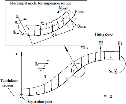
FIGURE 1. Schematic diagram of mechanical analysis of horizontal lifting of subsea pipeline.
According to the mechanical model shown in Figure 1, the equilibrium differential equation of the submarine pipeline can be written as:
Where: q is the weight per unit length of the pipeline in seawater; ds is the arc length of the selected micro-segment; Ft is the tangential wave and current force uniformly distributed along the pipeline axis; Fn is the normal wave and current force uniformly distributed perpendicular to the pipeline axis; N is the axial tension of the pipeline; Q is the shear force at the pipeline end; θ is the included angle between pipeline axis and horizontal plane; M is the bending moment at the end of the pipeline. The wave and current forces on the submarine pipeline can be calculated by the Morrison equations.
The normal component of current force:
The tangential component of current force:
The normal component of wave force:
The tangential component of wave force:
Where: Cn is the normal drag coefficient, Ct is the tangential drag coefficient, the numerical value of the drag coefficient changes with Reynolds number; Cm is the inertia force coefficient, the numerical value is 2; Uc is the resultant velocity of the current velocity v and the wave velocity u; vn=v·sin, vt=v·cos, they are the normal velocity and tangential velocity of the current, respectively; un=u·sin, ut=u·cos, they are the normal velocity and tangential velocity of the wave, respectively.
Since the lifting of the submarine pipeline belongs to the problem of large length-diameter ratio and large bending deformation, the axial deformation and the shear deformation of the pipeline can be ignored, and only the bending deformation of the pipeline can be considered, then the following relationships can be obtained:
Where: EI is the bending stiffness of the submarine pipeline; b is the length of the suspension section; y(s) and u(s) are the deflections and horizontal displacement at any point of the pipeline, respectively.
The boundary conditions of the S-type lifting can be simplified as follows: at the separation point, s=0, y (0)=0, θ(0)=0, u (0)=0, N (0)=0, M(0)=0; at the free end, s=b, N(b)·sin(b)-Q(b)·cos(b)=F, M(b)=M. The dimensionless parameter s/b is introduced into Eq. 1 to change the solution interval from (0, b) to (0,1). Other parameters such as deflection, bending moment, and shear force are also dimensionless simplified, just as shown in Eq. 10:
Substitute Eqs 7–9 into Eq. 3, then the following equation can be obtained:
Finally, the boundary problem of the suspension section can be solved by the above equations.
Establishment of dynamic simulation model
Environmental and pipeline parameters
The water depth is 18.7 m, the current direction is 180°, the current is 1 m/s, The type of wave spectrum is the Jonswap spectrum, the wave direction is 90°, The significant wave height Hs is 1m, and the mean zero-crossing period Tz is 11.35s.
The length of the pipeline is 1555 m, the outer diameter is 0.2191 m, the inner diameter is 0.194 m and Young’s modulus is 2.07 × 10⁵ MPa, Poisson ratio is 0.3, the density is 7.85 t/m3, the normal additional mass coefficient of the pipeline is 1, the axial additional mass coefficient of the pipeline is 0, the axial drag coefficient of the pipeline is 0.008, the normal drag coefficient of the pipeline is shown in Figure 2., and the lift coefficient of the pipeline is shown in Figure 3. The normal and axial friction coefficients between the pipeline and the seabed are both 0.5.
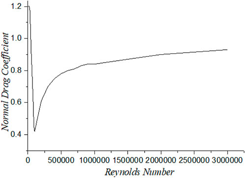
FIGURE 2. Normal drag coefficient of the pipeline versus Reynolds Number.
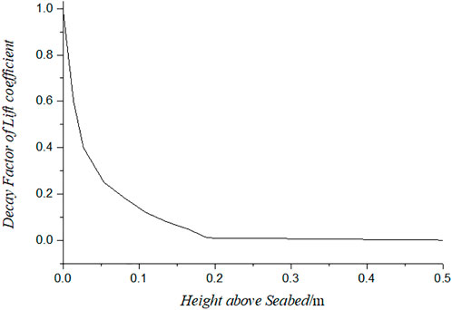
FIGURE 3. Lift coefficient of the pipeline versus height above seabed.
The influence of the shape, slope, and stiffness of the seabed on the lifting of submarine pipelines cannot be neglected. However, for the convenience of modeling, the seabed is simplified as a flat seabed with a vertical stiffness coefficient of 1.866 kN/m3 and a shear stiffness coefficient of 100 kN/m3. Soil resistance cannot be directly applied to the pipeline in OrcaFlex. There, to simulate the effect of the soil suction on the subsea pipeline, the Link unit is used in this paper to simulate the vertical soil resistance. Since the soil resistance of the pipeline Section 250 m away from the free end of the pipeline has little influence on the lifting operation, to simulate the normal resistance of the seabed within the range of 0–200 m near the lifting ship, a total of 200 Link units are arranged, and every 1 m is a Link unit. This will make the numerical model more compatible with the actual lifting operation and make the data more reliable.
Establishment of dynamic simulation model
The pipeline part of 0–250 m near the operation area of the lifting ship is the area with obvious pipeline deformation, so the segment length of this part is 1m, and it is divided into 250 units in total. The unit length of the remaining 1305 m pipeline is 5 m, and it is divided into 261 units in total. Therefore, the entire pipeline is divided into 511 segmented units. A Link unit is connected to a circular buoy with a mass of 0.005t and a volume of 5 m3 at the length direction of 73 m. The function of the buoy is mainly used to provide a certain buoyancy for the lifting operation.
Since the length of the lifting rope varies throughout the dynamic lifting process, the Winch unit with variable length is used to simulate the lifting rope. One end of the Winch unit is connected to the subsea pipeline and the other end is connected to the lifting ship. Three Winch units are arranged at the pipeline length direction of 8, 35, and 65 m, respectively. The coordinates of these three Winch units on the lifting vessel are (-27 m, -16.5 m, 6.78 m), (0 m, -12 m, 7 m), (30 m, -12 m, 7 m).
The position of the lifting ship remains unchanged, and the whole lifting process is mainly controlled by the length of the lifting rope. The length of the prolongation and contraction of the lifting rope at each stage needs to be determined according to the parameters of the winch and other equipment on the ship. In the simulation, to make the model converge more easily, the contraction process of the lifting rope will be realized through 24 analysis steps. Because submarine pipelines are generally buried under the seabed, the non-linear pipe-soil interaction will inevitably occur during the process of pipeline lifting, which can be simplified as vertical soil resistance, just as shown in Figure 4.
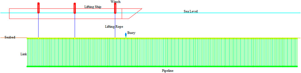
FIGURE 4. Multi-point horizontal lifting model.
Accuracy verification of the modeling method
To verify the accuracy of the modeling method, according to the actual situation of submarine pipeline laying and lowering under a certain working condition, the modeling method proposed in this paper is used for modeling, and the simulation modeling results are compared with the theoretical calculation results, just as shown in Figure 5.
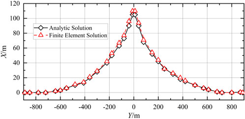
FIGURE 5. Verification of the modeling method.
It can be seen from Figure 5 that the configuration of the curve obtained during the lifting process of the submarine cable by the finite element solution in OrcaFlex is very similar to that of the analytical solution. The curves obtained by the two methods are convex from the middle and nearly symmetrical on both sides. By further observing the graph and comparing the data, it is found that the error between the two is less than 10%, which verifies the correctness of the modeling method proposed in this paper.
Calculation results
Effective tension of the pipeline
With the observation of the distribution of the effective tension in the length direction with different burial depths in Figure 6, it is found that the change of burial depth has a significant influence on the effective tension of the pipeline.
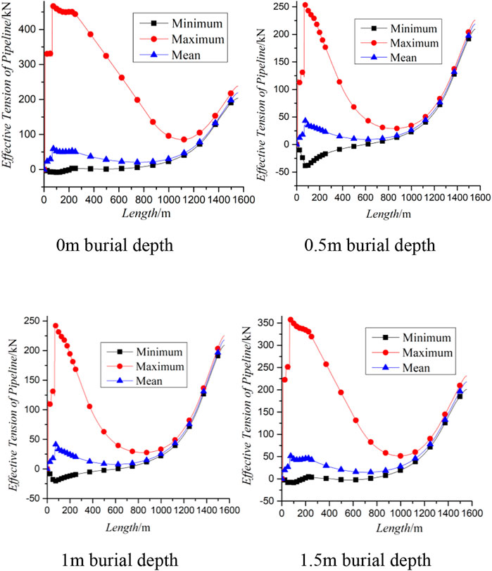
FIGURE 6. Effective tension of the pipeline in the length direction with different burial depths.
By comparing and observing the distribution curves of the maximum effective tension in the length direction with different burial depths, it can be seen that the change of the burial depth does not change the position where the maximum tension occurs. The maximum effective tension of the pipeline reflects the maximum degree of stretching that the pipeline is subjected to.
Further comparative observation shows that the maximum degree of stretching of the pipeline does not increase with the increase in burial depth of the pipeline. With the increase of the burial depth of the pipeline, when the burial depth of the pipeline increases to 0.5 m, compared with the burial depth of 0m, the maximum stretching degree decreases significantly. When the burial depth of the pipeline continues to increase to 1m, the maximum stretching degree decreases slightly. However, when the burial depth of the pipeline continues to increase to 1.5 m, the maximum effective tension of the pipeline at the point where the maximum stretching degree occurs increases again.
Further observation can be found that in the length range of 1,100m–1555 m, the curves of the maximum, minimum, and mean effective tension of the pipeline in the length direction are highly coincident, which indicates that the stretching effect of the lifting operation on the pipeline in this length range is almost constant in the time domain without much fluctuation.
With the observation of the distribution curves of the standard deviation of the effective tension in the length direction with different burial depths in Figure 7., it can be seen that the standard deviation of effective tension of the pipeline shows a tendency of repeated changes with the increase of the burial depth. When the burial depth of the pipeline is 0m, the standard deviation of the effective tension of the pipeline is the largest. When the burial depths are 0.5 and 1 m, the standard deviation curves of the effective tension of the pipeline are highly overlapped. When the burial depth is 1.5 m, the standard deviation of the effective tension of the pipeline is smaller than that with 0 m burial depth but larger than that with 0.5 m burial depth. Combined with the calculation results, it can be seen that a certain degree of burial depth during the lifting process may be helpful to reduce the degree of axial tension and the intensity of axial tension fluctuation, which may be helpful to reduce the fatigue damage of the pipeline during the lifting process.
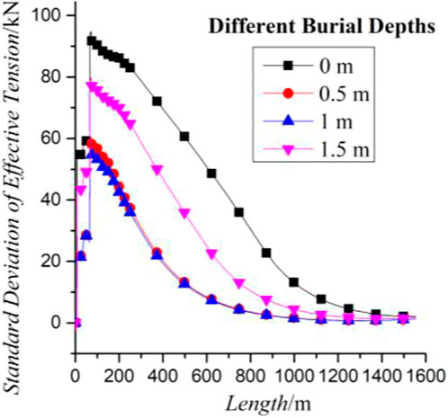
FIGURE 7. Standard deviation of the effective tension of the pipeline in the length direction with different burial depths.
Shear force of the pipeline
With the observation of the distribution of the shear force in the length direction with different burial depths in Figure 8., it can be seen that a small shear force will be generated at the end of the pipeline at 1555 m with different burial depths. It means that in the lifting process, as the pipeline is gradually lifted, the end of the pipeline near the seabed will be supported by the seabed, and this concentrated support increases with the increase of the lifting length of the pipeline, which is the reason for the small increase in shear force at the end of the pipeline.
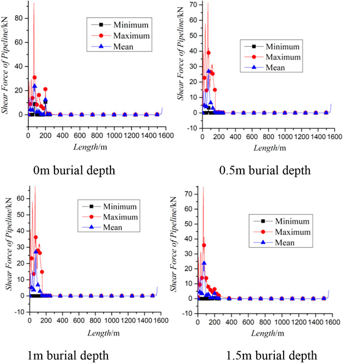
FIGURE 8. Shear force of the pipeline in the length direction with different burial depths.
Further observation shows that with the increase of the burial depth, the location of the maximum shear force in the length direction does not change significantly, but the magnitude of maximum shear force at the location of the maximum shearing action decreases first and then increases with the increase of the burial depth. Combined with the calculation results, it can be seen that in the lifting process, the pipeline will be subjected to both axial stretching and shearing effects, and both the shearing action and the axial stretching action are smaller when the burial depth is 1 m. This provides a possible choice for optimizing the burial depth of the pipeline, the lifting operation at this burial depth can reduce both the tensile force and the shear force of the pipeline.
With the observation of the distribution of the standard deviation of the shear force in the length direction with different burial depths in Figure 9., it can be seen that the degree of the shear force fluctuation of the pipeline is the same with different burial depths, which indicates that the change of the burial depth is the main reason for the numerical value of the shear force.
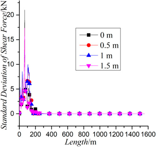
FIGURE 9. Standard deviation of the shear force of the pipeline in the length direction with different burial depths.
It means that the change of burial depth for the change of shear action is mainly reflected in the change of the numerical value of the shear force, and has no significant impact on the degree and variation fluctuation of the shear force.
Bending moment of the pipeline
By observing the distribution of the bending moment in the length direction with different burial depths in Figure 10., it can be seen that there is no significant difference in the distribution of the bending moment in the length direction of the pipeline with the increase of the burial depth, which shows that the increase of burial depth does not bring about an obvious increase of the bending moment. In a sense, it means that within a certain range, the change of the burial depth will not lead to a significant increase in the bending moment of the pipeline during the lifting process.
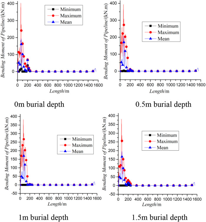
FIGURE 10. Bending moment of the pipeline in the length direction with different burial depths.
With the observation of the distribution of the standard deviation of the bending moment in length direction with different burial depths in Figure 11., it can be seen that the bending intensity of the pipeline does not increase with the increase of the burial depth, and the area where the pipeline bends more intensely is also the area where pipeline bears larger bending moment. This indicates that the location where the bending transfer of the pipeline is discrete in the time domain is the location where the maximum bending moment of the pipeline is likely to occur.
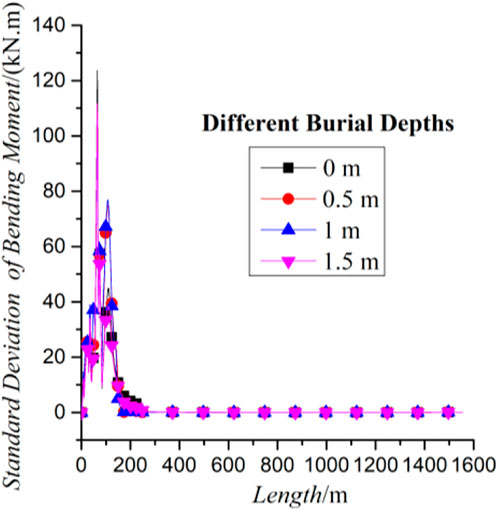
FIGURE 11. Standard deviation of the bending moment of the pipeline in the length with different burial depths.
Curvature of the pipeline
With the comparison and observation of the curve distribution configurations of the bending moment and curvature in the length direction with different burial depths in Figure 12., it can be found that the distribution configurations of the bending moment curve and the curve of the curvature in the length direction are highly similar at the same burial depth. It means that the bending moment and curvature change synchronously, and there is no hysteresis in the bending deformation of the pipeline during the lifting process.
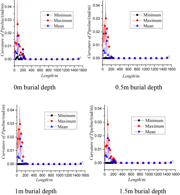
FIGURE 12. Curvature of the pipeline in the length direction with different burial depths.
By comparing and observing the curve distribution configurations of the standard deviation of the bending moment and the standard deviation of the curvature of the pipeline in the length direction with different burial depths in Figure 13., it can be found that the distribution configurations of the standard deviation curve of the bending moment and the standard deviation curve of the curvature of the pipeline in the length direction at the same burial depth are highly similar, which again shows the high consistency of the change of the bending moment and the change of the curvature caused by the bending action in the time domain. It also shows that the parts with sharp bending changes have large bending moments and curvature.
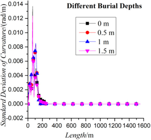
FIGURE 13. Standard deviation of the curvature of the pipeline in the length direction with different burial depths.
Von Mises stress of the pipeline
With the observation of the distribution of von Mises stresses in the length direction with different burial depths in Figure 14., it can be seen that the change of the burial depth has little effect on von Mises stresses, and von Mises stresses are almost zero in the length range of 200–800 m, which again verifies the correctness of the calculation. The bending moment and the shear force of the pipeline are also 0 in the length range of 200–800 m, which is the reason for the phenomenon that von Mises stress is 0 in this length range.
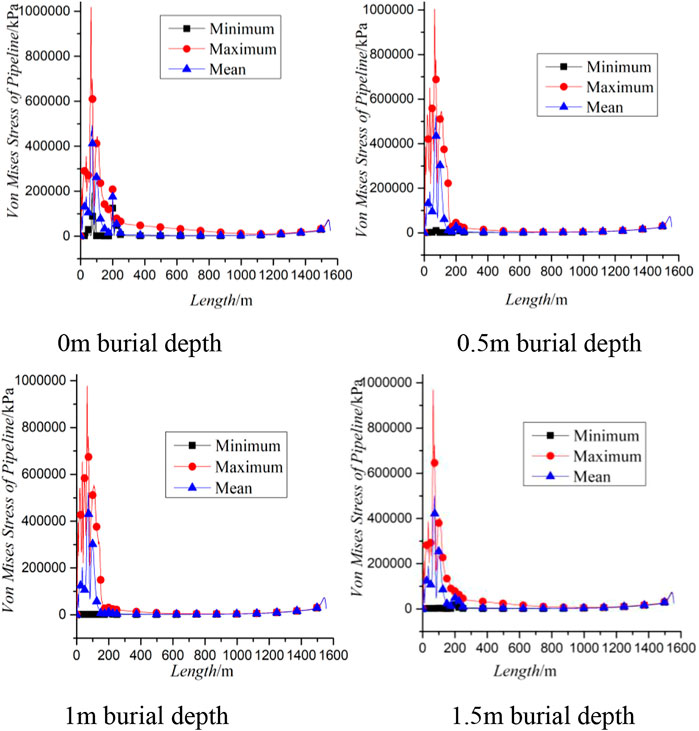
FIGURE 14. Von Mises stresses the pipeline in the length direction with different burial depths.
However, it can be found that the distributions of von Mises stress in the length range of 0–200 m with different burial depths have some differences. It means that von Mises’ stresses show a complex trend in this length range. The generation of von Mises stress is inseparable from the combined loads such as tensile, bending, and shearing of the pipeline. Therefore, the part with high von Mises stress is also the part where the pipeline is subjected to large bending, tensile and shearing loads during the lifting process.
By observing the distribution of von Mises stress standard deviation in the length direction with different burial depths in Figure 15., it can be seen that the standard deviation of von Mises stress tends to zero in the range of 200–1555 m, which indicates that von Mises stress is not only small in this range of length but also the intensity of von Mises stress fluctuation is also very small, the reason for this phenomenon is that section in the range of 200–1555 m is far from the operation area.

FIGURE 15. Standard deviation of Von Mises of the pipeline in the length direction with different burial depths.
Conclusion
1) The change of burial depth has a significant influence on the effective tension of the pipeline. The maximum effective tension of the pipeline reflects the maximum degree of stretching that the pipeline is subjected to. With the increase of the burial depth of the pipeline, the maximum degree of stretching of the pipeline first decreases and then increases. A certain degree of burial depth during the lifting process may be helpful to reduce the degree of axial tension and the intensity of axial tension fluctuation, which may be helpful to reduce the fatigue damage of the pipeline during the lifting process.
2) As the pipeline is gradually lifted, the end of the pipeline near the seabed will be supported by the seabed, and this concentrated support increases with the increase of the lifting length of the pipeline. This is the reason for the small increase in shear force at the end of the pipeline. In the lifting process, the shearing action and the axial stretching action are smaller when the burial depth is 1 m. This provides a possible choice for optimizing the burial depth of the pipeline. The change of burial depth for the change of shear action is mainly reflected in the change of the numerical value of the shear force.
3) Within a certain range, the influence of the bending factors on the pipeline does not need to be considered too much during the lifting process. And the part with high von Mises stress is also the part where the pipeline is subjected to large bending, tensile and shearing loads during the lifting process.
Data availability statement
The original contributions presented in the study are included in the article/supplementary material, further inquiries can be directed to the corresponding author.
Author contributions
Investigation, DZ and BZ; methodology, DZ and BZ; writing original draft preparation, DZ and KZ; writing review and editing, BZ. All authors have read and agreed to the published version of the manuscript.
Funding
This work was supported by the Program for Scientific Research Start-up Funds of Guangdong Ocean University under Grant 060302072101; Comparative Study and Optimization of Horizontal Lifting of Subsea Pipeline under Grant 2021E05011.
Conflict of interest
The authors declare that the research was conducted in the absence of any commercial or financial relationships that could be construed as a potential conflict of interest.
Publisher’s note
All claims expressed in this article are solely those of the authors and do not necessarily represent those of their affiliated organizations, or those of the publisher, the editors and the reviewers. Any product that may be evaluated in this article, or claim that may be made by its manufacturer, is not guaranteed or endorsed by the publisher.
References
Ajayi, O. O., and Aribike, O. O. (2015). Modelling and simulation of subsea umbilical dynamics: A numerical approach. Int. J. Comput. Thechniques 2 (1), 12.
Amdal, L. W., Rneid, S., and Etterdal, B. (2011). “Optimised design of pipelines exposed to trawl pull-over,” in ISOPE-2011 Maui;International offshore and polar engineering conference.
Bai, Y., Zhang, D., Zhu, K., and Zhang, T. (2018). Dynamic analysis of umbilical cable under interference with riser. Ships Offshore Struct. 13 (8), 1–13. doi:10.1080/17445302.2018.1460082
Bruschi, R., Vitali, L., Marchionni, L., Parrella, A., and Mancini, A. (2015). Pipe technology and installation equipment for frontier deepwater projects. Ocean. Eng. 108, 369–392. doi:10.1016/j.oceaneng.2015.08.008
Cui, Y. (2007). Lifting analysis and program development of pipelines in beach and sea area, Master Thesis. Tianjin: Tianjin University.
Custodio, A., and Vaz, M. (2002). A nonlinear formulation for the axisymmetric response of umbilical cables and flexible pipes. Appl. Ocean Res. 24, 21–29. doi:10.1016/s0141-1187(02)00007-x
De Sousa, J., Viero, P., Magluta, C., and Roitman, N. (2012). An experimental and numerical study on the axial compression response of flexible pipes. J. Offshore Mech. Arct. Eng. 134 (3), 031703. doi:10.1115/1.4005181
Gao, Q., Duan, M., Liu, X., Wang, Y., Jia, X., An, C., et al. (2018). Damage assessment for submarine photoelectric composite cable under anchor impact. Appl. Ocean Res. 73, 42–58. doi:10.1016/j.apor.2018.01.006
Gao, Y., Wei, H., Jiang, Y., Wang, Y., et al. (2014). Current technology and development trend of process facilities in deep water subsea production system. China Offshore Oil Gas 26 (4), 84–90.
Gong, S., Chen, K., Chen, Y., Jin, W., Li, Z., and Zhao, D. (2011). Configuration analysis of deepwater S-lay pipeline. China Ocean. Eng. 25 (3), 519–530. doi:10.1007/s13344-011-0042-5
Gong, S., Xu, P., Bao, S., Zhong, W., He, N., and Yan, H. (2014). Numerical modelling on dynamic behaviour of deepwater S-lay pipeline. Ocean. Eng. 88, 393–408. doi:10.1016/j.oceaneng.2014.07.016
Gong, S., and Xu, P. (2016). The influence of sea state on dynamic behaviour of offshore pipelines for deepwater S-lay. Ocean. Eng. 111, 398–413. doi:10.1016/j.oceaneng.2015.11.013
Gong, S., Zhang, T., Wang, X., and Liu, C. (2020). Numerical simulation on dynamic behaviour of deepwater J-lay systems. Ocean. Eng. 196 (15), 106771. doi:10.1016/j.oceaneng.2019.106771
Guo, X., Nian, T., Wang, D., and Gu, Z. d. (2022). Evaluation of undrained shear strength of surficial marine clays using ball penetration-based CFD modelling. Acta Geotech. 17 (5), 1627–1643. doi:10.1007/s11440-021-01347-x
Guo, X., Nian, T., Zhao, W., Gu, Z., Liu, C., Liu, X., et al. (2022). Centrifuge experiment on the penetration test for evaluating undrained strength of deep-sea surface soils. Int. J. Min. Sci. Technol. 32 (2), 363–373. doi:10.1016/j.ijmst.2021.12.005
Knapp, R. H., and Shimabukuro, T. S. (2007). “Structural analysis of composite umbilical cables,” in The Seventeenth International Offshore and Polar Engineering Conference.
Liu, Z., Guo, H., Li, P., Li, F., Gu, H., An, W., et al. (2022). Experimental investigation on the vortex-induced vibration (VIV) suppression of the umbilical cable attached with helical strakes. Nav. Eng. J. 134 (1), 117–132.
Longva, V., and Sævik, S. (2013). A penalty-based contact element for pipe and 3D rigid body interaction. Eng. Struct. 56, 1580–1592. doi:10.1016/j.engstruct.2013.07.025
Martinelli, L., Lamberti, A., Ruol, P., Ricci, P., Kirrane, P., Fenton, C., et al. (2010). “Power umbilical for ocean renewable energy systems-feasibility and dynamic response analysis,” in Proc. Int Conf Ocean Energy.
Morison, J. R., Johnson, J. W., Schaaf, S. A., et al. (1950). The force exerted by surface waves on piles. J. Petroleum Technol. 2 (5), 149–154. doi:10.2118/950149-g
Næss, A., and Moan, T. (2013). Stochastic dynamics of marine structures. Cambridge: Cambridge University Press.
Qiao, F. (2010). Development for the strength analysis program of submarine pipeline lifting, Master Thesis. Tianjin: Tianjin University.
Qu, Y., Liu, X., Yi, P., et al. (2012). A finite element analysis of the multi-point hoist of offshore pipeline. China Pet. Mach. (3), 53–56.
Saevik, S. (2011). Theoretical and experimental studies of stresses in flexible pipes. Comput. Struct. 89 (2324), 2273–2291. doi:10.1016/j.compstruc.2011.08.008
Sævik, S., and Ye, N. (2015). Aspects of design and analysis of offshore pipelines and flexibles. Chengdu: Southwest Jiaotong University Press.
Wang, J., and Duan, M. (2015). A nonlinear model for deepwater steel lazy-wave riser configuration with ocean current and internal flow. Ocean. Eng. 94, 155–162. doi:10.1016/j.oceaneng.2014.11.025
Wang, J., Duan, M., Wang, Y., Li, X., and Luo, J. (2015). A non-linear mechanical model for deepwater steel lazy-wave riser transfer process during installation. Appl. Ocean Res. 50, 217–226. doi:10.1016/j.apor.2015.02.004
Keywords: lumped mass model, three-point horizontal lifting, subsea pipelines, burial depth, dynamic characteristics
Citation: Zhang D, Zhao B and Zhu K (2022) Mechanical characteristics analysis of horizontal lifting of subsea pipeline with different burial depths. Front. Earth Sci. 10:1011291. doi: 10.3389/feart.2022.1011291
Received: 04 August 2022; Accepted: 02 September 2022;
Published: 19 September 2022.
Edited by:
Guang-Liang Feng, Institute of Rock and Soil Mechanics (CAS), ChinaReviewed by:
Hao-sen Guo, East China Jiaotong University, ChinaGang Liu, Heilongjiang University of Science and Technology, China
Copyright © 2022 Zhang, Zhao and Zhu. This is an open-access article distributed under the terms of the Creative Commons Attribution License (CC BY). The use, distribution or reproduction in other forums is permitted, provided the original author(s) and the copyright owner(s) are credited and that the original publication in this journal is cited, in accordance with accepted academic practice. No use, distribution or reproduction is permitted which does not comply with these terms.
*Correspondence: Bowen Zhao, c2Vhd29sZl96YndAMTYzLmNvbQ==