 Sun Yang1
 Ding Haibin
 Tong Lihong
- 1Jiangxi Transportation Institute Co., LTD, Nanchang, Jiangxi, China
- 2State Key Laboratory of Performance Monitoring and Protecting of Rail Transit Infrastructure, East China Jiaotong University, Nanchang, Jiangxi, China
- 3Institute of Geotechnical Engineering, School of Civil Engineering and Architecture, East China Jiaotong University, Nanchang, Jiangxi, China
In this research, under the disturbance of pre-dewatering, the analytical solution of vertical displacement of the adjacent tunnel is derived using the two-stage analysis method. In the first stage, the effective stress principle was used to calculate the additional stress of the adjacent tunnel caused by dewatering. In the second stage, the Pasternak-Timoshenko beam model was used to simulate the interaction between the tunnel and soil, taking the tunnel shear deformation into account. By referring to the calculation results of existing literature, the correctness of the proposed method is verified, and the influencing factors of the longitudinal displacement of the tunnel are further analyzed. The results show that with the increase of the distance from the dewatering well and soil elastic modulus, the vertical displacement of the tunnel is reduced. The deformation of the existing tunnel increases with the permeability coefficient. The decrease of the tunnel shear modulus can lead to the rapid increase of the tunnel’s vertical displacement, so the shear stiffness should be considered in the analysis of its deformation. The increase in the dropping amplitude of the water level in the well will decrease the water level in the surrounding strata. According to the different relative positions of the tunnel and the water table, there are two forms of additional load on the tunnel. Before the water level drops to the tunnel axis, the tunnel’s Additional load and displacement gradually increase.
1 Introduction
Foundation pit excavation is an effective means of underground space development. However, pre-dewatering is necessary for foundation pit engineering to improve construction conditions. In the process of dewatering, the effective stress of soil mass under the original water level will increase (Wang et al., 2013) to have a harmful effect on the existing tunnel, which is one of the main reasons for the long-term settlement of the tunnel (Zeng et al., 2019; DING et al., 2021). Therefore, investigating the longitudinal settlement of the adjacent tunnel subjected to pre-dewatering is crucial for operation safety.
At present, many scholars have studied the influence of pre-dewatering on the adjacent tunnel. For example, taking the excavation project of Shenzhen Kerry Construction Square Phase II as a research subject, (Zhang and Pan, 2013) found that the pre-dewatering of this project caused a settlement of 5.7 mm in the adjacent subway tunnel, which did not meet the requirements of metro track deformation. Liu (2013) established a numerical model to study the influence of dewatering on the adjacent subway tunnel in the excavation project of Tianjin West Railway Station. Taking an excavation project of Changsha Line 5 as an example, (Huang et al., 2018) studied the sensitivity of adjacent subway tunnels to excavation dewatering velocity by combining Biot consolidation theory and Midas GTS finite element software. Combining the finite difference method with fluid-structure coupling theory, (Jia et al., 2010) studied the stress and deformation law of the existing municipal tunnel in the process of dewatering for a new tunnel project in Chengdu. According to the geological characteristics of underground water in Shanghai, (Li, 2008) studied the influence of excavation dewatering on the longitudinal deformation of operating metro tunnels.
At present, there are few theoretical studies on the longitudinal deformation of adjacent tunnels caused by dewatering. Combining the effective stress principle with the Pasternak foundation model, (Xu et al., 2021) used the Euler-Bernoulli beam to simulate pipelines based on the two-stage theoretical method and deduced analytical solutions for the deformation of adjacent pipelines caused by dewatering. Under the influence of excavation and dewatering, (Zhang et al., 2017) used the two-stage theoretical method to study the deformation of the underlying tunnel and used the Euler-Bernoulli beam to simulate the tunnel, and found that the influence of excavation dewatering on the underlying tunnel should not be ignored.
In the existing studies on the deformation of shield tunnels, the shield tunnel is usually simplified as an Euler-Bernoulli beam (Zhang and Zhang, 2013; Liang et al., 2016; Liang et al., 2018). However, unlike pipelines, the shield tunnel is multi-segment ring-shaped segment splintering so that the Euler-Bernoulli beam will ignore the shear deformation generated by the tunnel. This will cause an error in the calculation. In recent years, some scholars have chosen to adopt the Timoshenko beam simulation tunnel (Li et al., 2015; Liang et al., 2017; Zhang et al., 2019; Liang et al., 2021) that can consider shear deformation.
To sum up, this paper is based on the two-stage method, the effective stress principle and Dupuit assumption are adopted in the first stage to calculate the additional stress of the adjacent tunnel caused by dewatering. In the second stage, the Timoshenko beam is used to simulate the tunnel while considering the shear deformation, and the Pasternak foundation model is used to simulate the interaction between the tunnel and soil. Then, the analytical solution of vertical displacement of adjacent tunnel caused by excavation dewatering is derived considering the shear deformation of the tunnel. Finally, the accuracy of the proposed method is verified by referring to the current literature results. The influence of the distance between the tunnel and the dewatering well, the tunnel shear modulus, the elastic modulus of soil, the permeability coefficient of soil, and the water level drawdown on the longitudinal displacement of the tunnel are studied.
2 Establishment of the equation
The influencing range of excavation pre-dewatering on the surrounding water level is defined as the dewatering radius, and the existing shield tunnel within the dewatering radius will be affected by the dropping in the surrounding water level. As shown in Figure 1, A is the dewatering well, the dewatering radius is R, and the distance between the tunnel and the dewatering well is d. The X-axis is set along the tunnel direction, and the O point on the tunnel axis, that is, the nearest to the dewatering well is taken as the origin. Point B and point C are the intersection points between the dewatering radius and the tunnel.
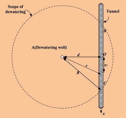
FIGURE 1. Radius of dewatering.
2.1 Effective stress induced by pre-dewatering
Within the dewatering radius, the dewatering will cause a funnel-shaped dewatering curve in the soil; as shown in Figure 2, R0 is the radius of the dewatering well, H0 is the initial water level height of the phreatic aquifer, and Ht is the water level height in the well after dewatering. Based on Dupuit’s assumption, the flow rate at different water levels is equal to the amount of water pumped from the well (Verruijt, 1982):
where r is the horizontal distance from the well, h is the water level height at this position, and kt is the permeability coefficient of soil. The dewatering curve h(r) can be obtained by substituting the water level boundary conditions of the dewatering well
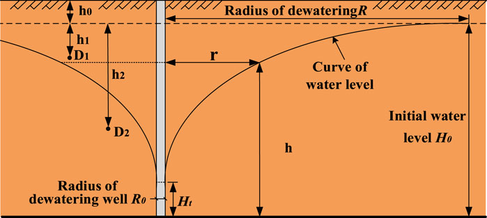
FIGURE 2. Curve of water level after dewatering.
According to Sakukin’s formula, the dewatering radius can be calculated by
As shown in Figure 2, point D1 is above the water level after dewatering, and point D2 is below the water level after dewatering. Therefore, the effective stress increment σ1 and σ2 of the two points can be calculated as follows:
where σt and σ0 are the effective stresses of D1 and D2 points before and after dewatering, respectively; and h0 is the buried depth of the initial water level from the ground surface; h1 and h2 are the elevation differences between D1 and D2 points and the initial water level, respectively; γ, γs and γw are unit weight and saturated unit weight of soil, and unit weight of water, respectively.
Above and below the water level, their effective stress increments after dewatering are different. According to the relative position of the tunnel and water level, the additional stress caused by dewatering is different. Therefore, the additional stress caused by dewatering can be calculated in two cases: all parts of the tunnel are below the water level after dewatering, and part of the tunnel is above the water level, as shown in Figure 3. Based on the coordinate system established in Figure 1, the additional stress on the tunnel under the two conditions is calculated as follows:
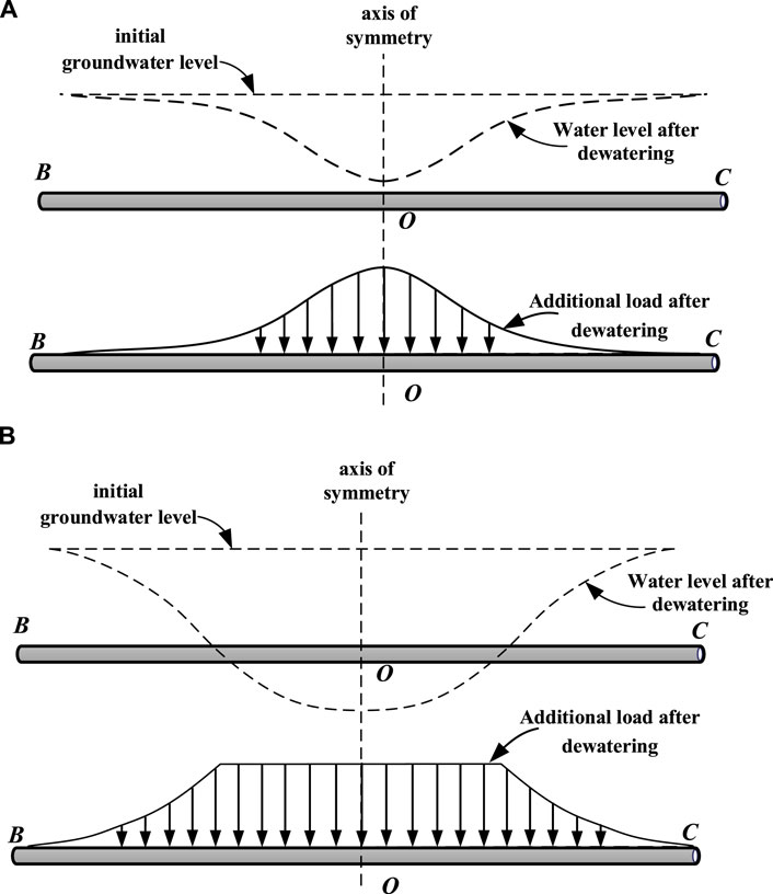
FIGURE 3. Water level and additional load distribution along tunnel length after dewatering:(A) water level is above the tunnel after dewatering; (B) part of the water level is below the tunnel after dewatering.
When the tunnel is below the water level, the distance between any point on the tunnel and the dewatering well
When the tunnel is partially located above the water level, the additional stress of the tunnel is divided into two parts. The additional stress of the tunnel above the water level is the same and is a fixed value.
where h1 is the height difference between the buried depth of the tunnel axis and the initial water level. The calculation of additional stress of other tunnels located below the water level is similar to Eq. 4. When h(r)= H0-h1, it is the intersection point between water level and tunnel, so the coordinate of this point can be obtained as
In this review, when the tunnel part is located above the water level, the formula for calculating the additional stress of the tunnel is:
2.2 Establishment of the governing equation of the timoshenko beam
The longitudinal deformation of the shield tunnel is composed of bending and shear deformation (Shen et al., 2014; Wu et al., 2015). When the traditional Euler-Bernoulli beam is used to simulate a shield tunnel, the tunnel is regarded as a structure with infinite shear strength, so the shear deformation of the tunnel is ignored. Since shield tunnels are composed of annular segments, unlike continuous structures such as pipelines, Euler-Bernoulli beams will underestimate the longitudinal deformation. The Timoshenko beam can take into account the shear deformation of the tunnel under additional loads (Li et al., 2015). In addition, the Pasternak foundation model can consider the continuity of foundation deformation and simulate the interaction between soil and tunnel well (Xu et al., 2021). Therefore, the tunnel is considered an infinitely long Timoshenko beam on the Pasternak foundation in this research to take into account the shear deformation generated by the tunnel, as shown in Figure 4. The section of the Timoshenko beam is no longer perpendicular to the neutral axis but crosses the normal direction of the neutral axis with an angle due to shear deformation. The stress deformation mode is more complex than the Euler-Bernoulli beam, as shown in Figure 5.
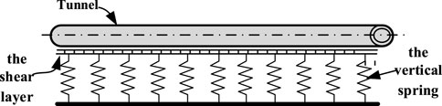
FIGURE 4. Pasternak-Timoshenko foundation beam model.
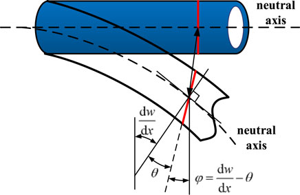
FIGURE 5. Timoshenko beam deformation mode.
According to Timoshenko beam deformation theory, the relationship between tunnel bending moment M, shear force, and Q and displacement w is:
where κ is the equivalent section coefficient, the tunnel is the annular section, κ= 0.5; G is the tunnel shear modulus, G=Et/2(1+vt); vt is Poisson’s ratio of tunnel; A is the annular section area of the tunnel; Et is the elastic modulus of the tunnel; It is the moment of inertia of the tunnel. According to the equilibrium differential equation:
where q(x) is the additional load generated by dewatering, q(x)= σ(x); D is tunnel diameter. p(x) is the ground reaction force. According to the Pasternak foundation model, p(x) is obtained as
where k and gs are the elastic coefficient and shear coefficient of the foundation, respectively, which can be calculated as follows (AttewellB et al., 1986; Tanahashi, 2004):
where Es soil elastic modulus; v is Poisson’s ratio of soil; t is the soil shear layer thickness, and t=6D is used for calculation (Xu, 2005).
Through Eqs. 8–12, the governing equation of tunnel displacement w(x) can be obtained as:
3 Solving the governing equation
Based on the derivation process of Guan et al. (Guan et al., 2021), Eq. 15 was solved according to q(x)=0, and the general solution was obtained:
where A1, A2, A3, and A4 are undetermined coefficients;
When the tunnel is subjected to concentrated load P at x=0, the boundary conditions of the tunnel are as follows:
After substituting Eqs. 17a–17c into Eq. 16, the calculation of the tunnel displacement under concentrated load P can be obtained as follows:
It can be known from the literature (S Selvadurai, 1984) that the additional load caused by dewatering is regarded as many segments of tiny concentrated load by adopting the micro-element method and then superimposed according to Eq. 13. The additional deformation of the tunnel under the action of dewatering can be calculated by employing integration. According to Eq. 15, the right-hand side of the Equation is regarded as Q(x), and the concentrated load P(ξ) at any point ξ on the tunnel is
Substituting the distributed load Q(x) into Eq. 18, the vertical displacement dw(x) of the tunnel is:
In the influence range of pre-dewatering, the vertical displacement of the tunnel caused by dewatering can be obtained by integrating Eq. 20:
4 Verification
Under the impact of pre-dewatering in the excavation, the tunnel deformation of the existing subway line one of Xifeng Road of Chegongmiao Junction of Shenzhen Metro in reference (Zhang et al., 2017) is used to verify the proposed method. The initial water level of the project is h0=1 m, the longitudinal length of the excavation L=30 m, transverse width B=20 m, and excavation depth is 8 m. The tunnel is vertically below the excavation and parallel to the excavation longitudinally, with a buried depth h2=14 m, diameter D=6 m, and tunnel wall thickness is 0.3 m. The relative position of the tunnel and the excavation is shown in Figure 6. C50 concrete is generally used for the segment since its elastic modulus Et=34.5 GPa, Poisson’s ratio vt=0.3, and the tunnel is in the gravel clay soil layer, the elastic modulus of soil is Es=60 MPa, Poisson’s ratio v=0.3, unit weight of soil γ=19.9 kN/m2, and saturated unit weight of soil γs=20.4 kN/m2. Other relevant parameters can be referred to literature (Zhang et al., 2017).
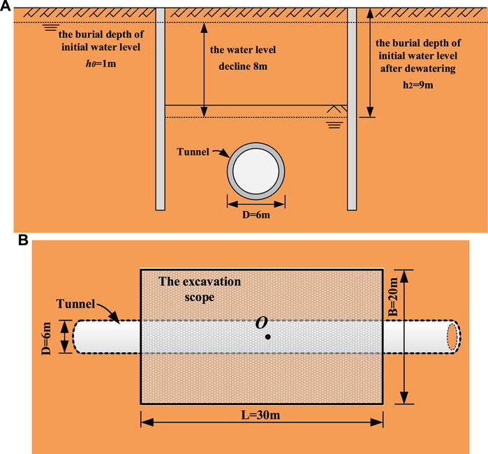
FIGURE 6. Engineering schematics: (A) sectional view; (B) plan view.
After pre-dewatering, the water level is dropped by sw=8 m to be h=9 m, and the tunnel becomes to be under the water level. In addition, only the water falling within the scope of the excavation is considered in the literature (Zhang et al., 2017), but the dewatering radius is not considered. According to Eq. 4, the additional stress received by the tunnel in the pit range is 75.7 kPa.
Figure 7 compares the calculation results of the proposed method, the Winkler-Euler-Bernoulli model, and the results of reference (Zhang et al., 2017). The origin of the abscissa is located at the midpoint of the tunnel in the pit, so the tunnel subjected to additional load caused by dewatering is in the range −15 ≤ x ≤ 15. It can be seen from Figure 7 that the maximum longitudinal deformation of the tunnel in the results of Reference 10 is −4.386 mm, and the maximum longitudinal deformation calculated by the method in this paper and the Winkler-Euler-Bernoulli model is −4.406 and −5.262 mm, respectively. In contrast, the calculated results in this paper are closer to those in reference 10. Because the Winkler-Euler-Bernoulli model cannot consider tunnel and foundation soil shear deformation, the Winkler calculation results are too large. Therefore, it is proved that the calculation method of tunnel displacement considering shear deformation under the action of dewatering is correct.
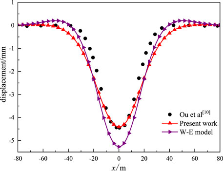
FIGURE 7. Comparison with existing literature.
5 Parameter analysis
The following calculation examples are designed for analyzing the influence of various factors on the displacement of the tunnel caused by dewatering, including initial water level H0=40 m, initial water depth h0=1 m, the radius of the dewatering well is R0=0.2 m, the water level in the well Ht=30 m after dewatering, and dropping of water level sw=10 m after pre-dewatering. Soil permeability kt=4.32 m/d, soil elastic modulus Es=30 MPa, Poisson’s ratio v=0.3, unit weight of soil γ=19 kN/m3, saturated unit weight of soil γs=20 kN/m3. The nearest distance between tunnel and dewatering well is D=10 m, buried depth z=10 m, h2=9 m, diameter D=6 m, the tunnel wall thickness is 0.3 m, elastic modulus Et=34.5 GPa, Poisson’s ratio vt=0.3, shear modulus Gp=13.27 GPa.
5.1 Distance d between tunnel and dewatering well
Five groups of tests are designed to study the influence of the distance d between the tunnel and the dewatering well on the tunnel deformation while the other parameters remain unchanged, whose distances are 6, 8, 10, 12, and 14 m, respectively. It can be seen from Figure 8 that when the spacing d increases from 6 to 14 m, the maximum vertical displacement of the tunnel decreases from 5.72 to 3.89 mm. This is because when the distance between the tunnel and the dewatering well gradually increases, the influence of dewatering on the tunnel is weakened. Therefore, the dewatering well should be as far away from the tunnel as possible to avoid excessive tunnel deformation in the project.
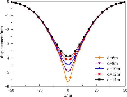
FIGURE 8. Curves of tunnel displacement under different spacing d.
5.2 Tunnel shear modulus Gp
Five groups of tests with different tunnel shear modulus Gp were taken to study its influence on tunnel deformation while the other parameters remained unchanged, including 1/125, 1/25, 1/5, and 5 times the original shear modulus. Figure 9 shows the tunnel displacement curves caused by pre-dewatering under different tunnel shear modulus Gp. As can be seen from Figure 9, when the tunnel shear modulus Gp decreases from 5 Gp to 1/125 Gp, the maximum vertical displacement of the tunnel rapidly and significantly increases from 4.38 to 14.93 mm. This is because when the shear modulus Gp decreases, the ability of the tunnel to resist the influence of dewatering is weakened. Therefore, strengthening the soil around the tunnel can reduce tunnel deformation.
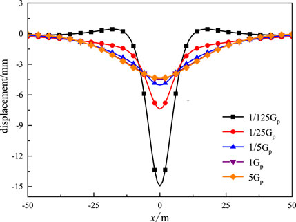
FIGURE 9. Curves of tunnel displacement under different tunnel shear modulus Gp.
5.3 Elastic modulus of soil Es
Five groups of tests with different soil elastic modulus Es were designed to study its influence on tunnel deformation while other parameters remained unchanged, which were 10, 20, 30, 40, and 50 MPa. It can be seen from Figure 10 that the maximum vertical displacement of the tunnel rapidly decreases from 12.36 to 2.75 mm as the soil elastic modulus Es increases from 10 to 50 MPa. That is, because when the elastic modulus of soil Es increases, the foundation is less likely to deform. On the other hand, when the tunnel bends, the foundation can provide a more significant reaction force to prevent tunnel deformation. Therefore, strengthening the soil around the tunnel can reduce tunnel deformation.
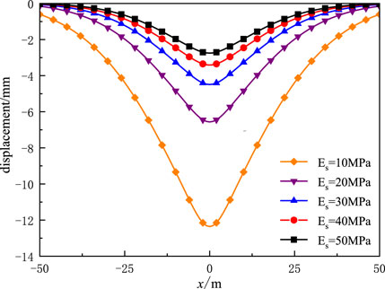
FIGURE 10. Curves of tunnel displacement under different Elastic modulus of soil Es.
5.3.1 Permeability coefficient kt
Five groups of tests with different permeability coefficient kt were taken to study its influence on tunnel deformation, which were 4.32×10⁻³, 4.32×10⁻², 0.432, 4.32, and 43.2 m/d. Figure 11 shows the tunnel displacement curves caused by pre-dewatering under different permeability coefficients kt. It can be seen from Figure 11 that the maximum vertical displacement of the tunnel increases from 3.64 to 5.00 mm as the permeability kt increases from 4.32×10⁻³ to 43.2 m/d. That is, because when the soil permeability kt rises, the influence of dewatering on the surrounding stratum water level increases. Therefore, a water stop curtain can be constructed between the dewatering well and the tunnel to reduce the influence of dewatering on the tunnel.
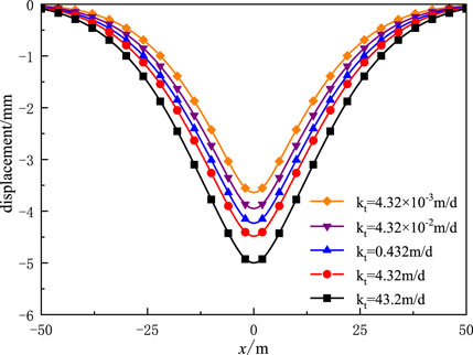
FIGURE 11. Curves of tunnel displacement under different permeability coefficients of soil kt.
5.4 Water level drawdown sw
Five groups of tests with different Ht were designed to study its influence on tunnel deformation while other parameters remained unchanged, which were 30, 25, 20, 15, and 10 m, and the corresponding sw was 10, 15, 20, 25, and 30 m respectively. Figure 12 shows the water level curve in the strata near the dewatering well under different water level dropping depths sw. It can be seen that with the increase of the dropping depth of water level sw in the well, the water level in the surrounding stratum also decreases, and the decreasing range gradually decreases. When the dewatering sw reaches 20 m, the groundwater level is still above the buried depth of the tunnel axis, and the additional stress on the tunnel can be calculated by Eq. 4. However, when sw of water level drawdown reaches 25 m, the part, that is, the closest to the dewatering well on the tunnel is already below the water level; In this case, the additional stress on this part is calculated by Eq. 5. Figure 13 shows the additional stress sustained by the tunnel under different water level drop depth sw. It can be seen that the additional stress on the tunnel increases with the increase of sw of the water level. This is because the more the water level drops, the less water buoyancy the soil above the tunnel receives. As shown in Figure 13, when sw reaches 25 and 30 m, the maximum value of the additional stress on the tunnel will not increase, and the range of the whole deal of the additional stress will expand. This is because part of the tunnel is already above the water level as sw=25 m. At the same time, as the sw continues to increase, more of the tunnel is located above the water level. However, the additional stress on the tunnel will not increase when the water level is below the tunnel. Therefore, the curves of sw =25 and sw =30 show inconsistent change trends compared with several other curves.
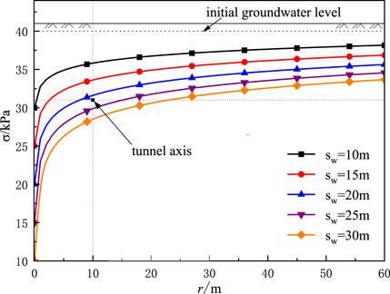
FIGURE 12. Curves of water level under different water level drawdown sw.
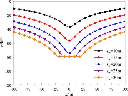
FIGURE 13. Curves of effective stress under different water level drawdown sw.
Figure 14 shows the tunnel displacement curve caused by pre-dewatering under different water level drop depth sw. It can be seen from Figure 14 that the maximum vertical displacement of the tunnel increases from 4.49 to −8.99 mm when the water level drawdown sw increases from 10 to 30 m, but the increased amplitude gradually weakens. That is, because when the water level drops depth sw gradually increases, the influence of dewatering on the surrounding water level also increases, which leads to the increase of the effect of dewatering on the tunnel. Furthermore, the drop in water level causes the increase of additional loads on the tunnel. Therefore, with the increase of sw, the tunnel displacement due to dewatering increases overall.
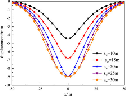
FIGURE 14. Curves of tunnel displacement under different water level drawdown sw.
6 Conclusion
Based on the proposed two-stage method, a theoretical calculation method for the vertical displacement of adjacent existing tunnels under the impact of pre-dewatering of excavation is proposed in this paper. In the first stage, the additional load induced by dewatering the tunnel was calculated. In the second stage, considering the shear effect, the Timoshenko beam model was used to simulate the deformation mode of the tunnel to derive the calculation of the tunnel displacement. After an in-depth Analysis, the following conclusions were drawn: DING et al., 2021.
1) With the increase in the distance between the tunnel and the dewatering well, the vertical displacement of the tunnel is reduced. The dewatering well should be as far away from the tunnel as possible to avoid excessive tunnel deformation in the project.
2) The decrease of the tunnel shear modulus Gp can lead to the rapid increase of the vertical displacement of the tunnel, so the influence of its shear stiffness should be considered when analyzing its deformation. Meanwhile, ensuring the shear stiffness of tunnels can effectively improve the ability of tunnels to resist external loads.
3) The growth of the elastic modulus of soil provides a more significant reaction force to prevent tunnel deformation. Therefore, strengthening the soil around the tunnel can reduce tunnel deformation.
4) When the soil permeability increases, the influence of dewatering on adjacent tunnels also increases. Therefore, a water stop curtain can be constructed between the dewatering well and the tunnel to reduce the influence of dewatering on the tunnel.
5) The increase of sw will lead to the overall decrease in water level in the surrounding strata. According to the relative position of the tunnel and the water table, there are two forms of additional load on the tunnel. Before the water level drops to the tunnel axis, the additional load on the tunnel increases with the water level drop depth sw, and the tunnel displacement also increases. When the water level drops below the tunnel axis, the additional load on the part above the water level is the same and does not increase with the increase of sw. Therefore, excessive dewatering should be avoided to reduce the influence of dewatering on adjacent tunnels in foundation pit dewatering engineering.
Data availability statement
The data used to support the findings of this study are available from the corresponding author upon request.
Author contributions
SY: Conceptualization, Data curation, Formal analysis, Funding acquisition, Investigation, Methodology, Writing—original draft, Writing—review and editing. RY: Funding acquisition, Data curation, Investigation, Methodology, Writing—review and editing. YJ: Conceptualization, Data curation, Investigation, Methodology, Validation, Writing—review and editing. ZL: Conceptualization, Investigation, Methodology, Writing—review and editing. DH: Data curation, Formal analysis, Investigation, Methodology, Validation, Writing—review and editing. TL: Conceptualization, Investigation, Methodology, Writing—review and editing.
Funding
This work was supported by National Natural Science Fund (52168049), the Key Program of the National Natural Science Foundation of China (52238009), Natural Science Fund of Department of transportation of Jiangxi Province (2021C0006, 2021Z0002, 2022Z0001, and 2022Z0002).
Conflict of interest
Author SY, RY, YJ, and ZL were employed by the company Jiangxi Transportation Institute Co., LTD.
The remaining authors declare that the research was conducted in the absence of any commercial or financial relationships that could be construed as a potential conflict of interest.
Publisher’s note
All claims expressed in this article are solely those of the authors and do not necessarily represent those of their affiliated organizations, or those of the publisher, the editors and the reviewers. Any product that may be evaluated in this article, or claim that may be made by its manufacturer, is not guaranteed or endorsed by the publisher.
References
AttewellB, P., Yeates, J., and Selby, A. R. (1986). Soil movements induced by tunnelling and their effects on pipelines and structures. London, United Kingdom; London:Blackie and Son Ltd, 128–132.
Ding, Z., Zhang, X., and Liang, F. Y., (2021). Research and prospects regarding the effect of foundation pit excavation on an adjacent existing tunnel in soft soil. China Journal of Highway and Transport. 34 (3), 21. in Chinese. doi:10.19721/j.cnki.1001-7372.2021.03.002
Guan, L. X., Xu, C. J., Ke, W. H., Ma, X. H., Xu, L. M., and Yu, W. W. (2021). Simplified method for calculating the vertical displacement of existing pipelines caused by tunnel undercrossing. Journal of Civil and Environmental Engineering. 43 (05), 66–72. in Chinese. doi:10.11835/i.issn.20966717.2020.158
Huang, K., Ma, Q., and Zhan, Y. Y. (2018). The influence of deep foundation excavation pit and dewatering on adjacent metro tunnel. Highway engineering. 43 (2). in Chinese.
Jia, Y. Y., Lu, J. J., Wei, L. L., and Cui, G. Y. (2010). Research on the influence of the tunnel dewatering construction on existed municipal pipeline tunnel. Hydrogeology Engineering Geology. 37 (6). in Chinese. doi:10.16030/j.cnki.issn.1000-3665.2010.06.025
Li, P., Du, S. J., Shen, S. L., Wang, Y. H., and Zhao, H. H. (2015). Timoshenko beam solution for the response of existing tunnels because of tunneling underneath. International Journal for Numerical and Analytical Methods Geomechanics. 40 (5), 766–784. doi:10.1002/nag.2426
Li, W. G. (2008). Influence of dewatering of adjacent excavation on longitudinal deformation of metro tunnel in operation, 73. Shanghai, China; Tongji university. in Chinese.
Liang, R., Wu, W., Yu, F., Jiang, G., and Liu, J. (2018). Simplified method for evaluating shield tunnel deformation due to adjacent excavation. Tunnelling and Underground Space Technology. 71 (1), 94–105. doi:10.1016/j.tust.2017.08.010
Liang, R., Xia, T., Hong, Y., and Yu, F. (2016). Effects of above-crossing tunnelling on the existing shield tunnels. Tunnelling and Underground Space Technology. 58 (9), 159–176. doi:10.1016/j.tust.2016.05.002
Liang, R., Kang, C., Xiang, L., Li, Z., Lin, C., Gao, K., et al. (2021). Responses of in-service shield tunnel to overcrossing tunnelling in soft ground. Environmental Earth Sciences. 80, 183. doi:10.1007/s12665-021-09374-3
Liang, R., Xia, T., Huang, M., and Lin, C. (2017). Simplified analytical method for evaluating the effects of adjacent excavation on shield tunnel considering the shearing effect. Computers and Geotechnics. 81 (1), 167–187. doi:10.1016/j.compgeo.2016.08.017
Liu, Y. S. (2013). Impact of the deep excavation dewatering on the settlement of a subway tunnel. Soil Engineering and Foundation 27. (1), 4. in Chinese.
S Selvadurai, A. P. (1984). Elastic analysis of soil-foundation interaction. Beijing, China; China Railway Publishing House, 42–57. in Chinese.
Shen, S. L., Wu, H. N., Cui, Y. J., and Yin, Z. Y. (2014). Long-term settlement behaviour of metro tunnels in the soft deposits of Shanghai. Tunnelling and Underground Space Technology. 40 (2), 309–323. doi:10.1016/j.tust.2013.10.013
Tanahashi, H. (2004). Formulas for an infinitely long Bernoulli-Euler beam on the Pasternak model. Japanese Geotechnical Society. 44 (5), 109–118. doi:10.3208/sandf.44.5_109
Verruijt, A. (1982). Theory of groundwater flow, 174. London, United Kingdom; Macmillan Education UK.
Wang, J. X., Feng, B., Yu, H. P., Guo, T. P., Yang, G. Y., and Tang, J. W. (2013). Numerical study of dewatering in a large deep foundation pit. Environmental Earth Sciences. 69 (3), 863–872. doi:10.1007/s12665-012-1972-9
Wu, H. N., Shen, S. L., Liao, S. M., and Yin, Z. Y. (2015). Longitudinal structural modelling of shield tunnels considering shearing dislocation between segmental rings. Tunnelling and Underground Space Technology. 50 (8), 317–323. doi:10.1016/j.tust.2015.08.001
Xu, C. J., Zeng, Y. T., Tian, W., and Chen, M. (2021). Analytical Analysis of the influence on adjacent pipelines induced by dewatering based on Pasternak model. Journal of Shanghai Jiaotong University. 55 (6), 11. in Chinese.doi:10.16183/j.cnki.jsjtu.2020.007
Xu, L. (2005). Research of the longitudinal settlement of soft soil shield tunnel, 69. Shanghai, China: College of Civil Engineering of Tongji University. in Chinese.
Zeng, C. F., Zheng, G., Zhou, X. F., Xue, X. L., and Zhou, H. Z. (2019). Behaviours of wall and soil during pre-excavation dewatering under different foundation pit widths. Computers and Geotechnics. 115, 103169. doi:10.1016/j.compgeo.2019.103169
Zhang, D. M., Huang, Z. K., Li, Z. L., Zong, X., and Zhang, D. M. (2019). Analytical solution for the response of an existing tunnel to a new tunnel excavation underneath. Computers and Geotechnics. 108 (4), 197–211. doi:10.1016/j.compgeo.2018.12.026
Zhang, H., and Zhang, Z. X. (2013). Vertical deflection of existing pipeline due to shield tunnelling. Journal of Tongji University. 8 (7). in Chinese.
Zhang, M., and Pan, B. Y. (2013). Influence on subway tunnel adjacent to excavation by dewatering. Science, Engineering and Technology. 21 (7). in Chinese.
Keywords: excavation dewatering, effective stress principle, Timoshenko beam, Pasternak foundation, adjacent tunnel
Citation: Yang S, Yao R, Junping Y, Liqing Z, Haibin D and Lihong T (2023) Theoretical study on longitudinal deformation of adjacent tunnel subjected to pre-dewatering based on Pasternak-Timoshenko beam model. Front. Earth Sci. 10:1114987. doi: 10.3389/feart.2022.1114987
Received: 03 December 2022; Accepted: 28 December 2022;
Published: 10 January 2023.
Edited by:
Xuelong Li, Shandong University of Science and Technology, ChinaReviewed by:
Zenian Wang, Jiangsu University, ChinaJunlong Sun, Kunming University of Science and Technology, China
Copyright © 2023 Yang, Yao, Junping, Liqing, Haibin and Lihong. This is an open-access article distributed under the terms of the Creative Commons Attribution License (CC BY). The use, distribution or reproduction in other forums is permitted, provided the original author(s) and the copyright owner(s) are credited and that the original publication in this journal is cited, in accordance with accepted academic practice. No use, distribution or reproduction is permitted which does not comply with these terms.
*Correspondence: Ding Haibin, aGJkaW5nQGVjanR1LmVkdS5jbg==