 Zhengjie Yan
 Wei Zheng1,2*†
 Fan Wu
 Cheng Wang
- 1School of Geomatics, Liaoning Technical University, Fuxin, China
- 2Qian Xuesen Laboratory of Space Technology, China Academy of Space Technology, Beijing, China
Improving the measurement accuracy is a necessary condition for sea surface altimetry using the Global Navigation Satellite System Reflectometry (GNSS-R). The ionosphere and troposphere delay the transmission of satellite signals, which directly affect the measuring accuracy. The influence of the atmospheric environment on GNSS-R altimetry differs from different platforms. By analyzing and sorting out the altimetry data of airborne and spaceborne platforms, this paper studies the variation law of signal delay in the altimetry process from the point of view of mathematical geometry, which provides an example for improving the precision of GNSS-R altimetry measurements. Firstly, in order to facilitate data analysis, this paper constructed an altimetry model with the GNSS satellite position, specular reflection point position, receiver position as nodes, classified direct signals, and reflected signals. Secondly, calculate ionospheric puncture point coordinates , and interpolate GIM products provided by IGS using time and puncture point coordinates to obtain the VTEC value in the vertical direction of the puncture point, which was converted into the path direction STEC by projection function, the ionospheric delay of each part was obtained in this way. The tropospheric delay of each part is considered for the along-path component and the geometric component, the delay of along-path component was calculated by the UNB3m model, and the delay of geometric component was calculated by the equation provided by Nikolaidou (Nikolaidou et al., 2021). Thirdly, by comparing the sea surface height inversion results with or without atmospheric delay correction with the mean sea surface height provided by DTU15, the measurement accuracy with atmospheric delay correction is obviously improved. The study results of the influence of atmospheric delay on the altimetry experiments precision error of airborne and spaceborne platforms show that the error magnitude is consistent with the existing literature. In the airborne experiment, the influence of the ionosphere is negligible and the troposphere has sub-meter influence on altimetry results, among which the tropospheric along-path delay component occupies a high proportion. The geometric delay component has a high correlation with the satellite elevation angle and its influence on the measurement accuracy decreases with the elevation angle increase. The effect of this factor can be effectively weakened by setting a high satellite cutoff angle. In the spaceborne experiment, the effect of atmospheric delay on altimetry results fluctuates in the range of 3∼5 m when the satellite elevation angle is greater than 60°. In this paper, the method of calculating signal atmospheric delay through geometric relation to improving the measurement accuracy can provide an example for the atmospheric delay correction of GNSS-R ocean altimetry with high precision and spatial resolution in future research.
Introduction
Sea surface height (SSH) is the basic data for the study of ocean dynamics, meteorology, geodesy, geophysics, geodesy, and other fields. The worldwide SSH can be used to monitor global climate change, obtain geoid, determine ocean circulation, invert the ocean gravity field, establish ocean tidal models, and conduct research on mesoscale climate models (Liu et al., 2019; Zhang et al., 2020b). It is of great significance to monitor sea level changes. At present, the SSH can be obtained from the traditional ship surveys and tidal stations to the present medium resolution spectrometer imaging, synthetic aperture radar, radar altimeter, and other methods (Liu et al., 2019; Hang et al., 2020). However, ship survey and tidal station models are limited in space, inefficient at spatial sampling, and suitable for local observation, unable to achieve global ocean coverage. Synthetic aperture radar altimeter and radar altimeter can only measure the target height of the subsatellite point and their application conditions are limited. At present, the famous Jason-2 altimeter satellite is jointly developed by CNES, NASA, EUMETSAT and NOAA, which can achieve the measurement of centimeter-level of SSH. It plays a huge role in weather forecasting and climate monitoring but its revisiting period is 9.9156 days and its coverage is concentrated in the sea, due to its lack of mesoscale spatial resolution results in that the surface water information at this scale cannot be observed steadily for a long time and cannot meet the application requirements of new ocean observation (Ren et al., 2018; Liu et al., 2019; Liu, 2020).
Global Navigation Satellite System Reflectometry (GNSS-R) Remote Sensing Technology is a new generation of altimetry technology which uses the reflection of GNSS signals on the sea surface to achieve altimetry (Hu et al., 2020a; Zhang et al., 2020b). In GNSS navigation and positioning, the reflected signals as multi-path interference are generally considered harmful when receiving direct signals and need to be suppressed and eliminated. However, from the point of view of electromagnetic wave propagation theory, the reflected signals carry the physical characteristics information of the reflecting surface, which can be obtained by the parameters change of reflected signals such as waveform, polarization characteristics, amplitude, phase, and frequency (Yang and Zhang, 2011). Therefore, it is possible to estimate and invert the physical properties of the reflecting surface by accurately receiving and estimating the reflected signals. Based on this theory, in 1993, ESA scientist Martin-Neira first proposed and described the concept of PARIS (passive reflectometry and interferometry system) using sea surface reflected signals (Martin-Neira, 1993). The main idea is to use the GPS sea surface reflected wave as the ranging signal to measure the ocean altimetry. In 1994, French scientist Auber accidentally found that the receiver could receive GPS sea surface reflected signals through flight tests (Auber et al., 1994). The Langley Research Center of NASA in the United States concluded, through the series of experiments, that the GPS reflected signals need a special receiver (Liu et al., 2007). Martin-Neira designed bridgeⅠ, bridgeⅡand bridge Ⅲ tests of PARIS altimeter in Holland in September 1997, June 2001, and February 2003 respectively, and verified the possibility of GNSS-R altimetry by using the methods of C/A code phase delay and carrier phase measurement (Martin-Neira et al., 2001; Caparrini et al., 2003; Rivas and Martin-Neira, 2006; Liu et al., 2007). In 2003, the GNSS-R equipment carried by the UK-DMC satellite successfully obtained surface physical coefficients such as sea surface roughness. In 2014, the first GNSS-R satellite (TDS-1) was launched (Jin et al., 2017). These achievements have stimulated the interest of many researchers in GPS reflected signals and prompted countries, world-wide, to begin the exploration and research of GNSS-R technology, and thus, GNSS-R technology has been developed rapidly.
GNSS-R Remote Sensing Technology is a new and effective dual-base radar passive remote sensing technology, compared with the traditional remote sensing technology, and it has the advantage of rich signal sources, low cost, wide-coverage, low power consumption, all-weather, high spatio-temporal resolution, and other advantages. At present, GNSS-R has been widely used in ocean wind measurement, ocean altimetry, sea ice detection, ocean salinity detection, soil moisture detection, moving target detection, and other fields. GNSS-R ocean altimetry technology mainly includes five methods, which are code delay altimetry, carrier phase altimetry, carrier frequency variation altimetry, interference altimetry, delay-doppler map (DDM) altimetry, and signal-to-noise ratio (SNR) altimetry (Hu et al., 2020a).
The realization of GNSS-R ocean altimetry depends on the transmission of GNSS electromagnetic wave signals in space. Signal propagation in space will be affected by the ionosphere, troposphere, multipath, and more. These factors, as error terms, will affect the accuracy of GNSS sea surface measurement, so it is necessary to eliminate the influence of these errors as much as possible (Camps et al., 2014; Zhang et al., 2020b). Literature (Katzberg and Garrison, 2001) pointed out that the ionosphere on the satellite altimeter uses the high frequency signal of dozens of centimeters of distance error, single frequency altimeter is useful in a low electron concentration areas with the scientific research needed, high-precision ionospheric correction is inevitable, and double-frequency altimeters on the spacecraft will produce cost and problem complexity. The GNSS-R technique is proposed by the author to determine the ionospheric electron density near the satellite and analyze the possibility of this technique. The literature (Ruffini et al., 2001) also studied the feasibility of using spaceborne GNSS-R technology to study the ionosphere. Through simulation experiments, the results showed that GNSS dual-frequency or multi-frequency signals could be used to estimate the ionospheric delay by GNSS-R technology and the dual-frequency pseudo-distance measurement and model prediction could be used to obtain the result that the measurement accuracy of 2 m could be improved after 1s integration. In terms of ionospheric detection, Chen Biyan proposed an improved ionization layer chromatography method which used the observation data of the ground GPS receiver to establish the regional ionospheric model and interpolated it to obtain sufficient TEC, and overcome the shortcomings of the empirical ionospheric model affected by spatial environment and distortion (Chen, 2012). Literature (Yan and Huang, 2016) proposed a method of using DDM to inversion the total electron content in the ionosphere over the ocean. The results are in good agreement with the IRI-2012 model. Based on the data of GPS, GLONASS, BDS and Galileo combined with MGEX network and IGS network, Ren Xiaodong established the ionospheric model based on the multi-system GNSS observation data and analyzed the accuracy of the model, and the results showed that the accuracy was similar to that of IGS products. At the same time, the un-difference ambiguity fixing technique is proposed to extract TEC. Compared with the traditional carrier phase smoothing pseudo distance, the accuracy of ionospheric TEC extracted by this method is significantly improved, which is of great value for the future extraction of TEC from short-period low-orbit satellite data (Ren, 2017). In other studies of GNSS-R application, researchers used models to correct atmospheric delay errors, which were divided into single-frequency navigation receivers using the global ionospheric model for correction, such as the Klobuchar model, and dual-frequency navigation receivers using a linear combination of carrier phase and pseudo-range code to eliminate ionospheric errors (Adriano et al., 2016). There is no systematic study on the variation law of atmospheric delay. In the study of the airborne GNSS-R reflected signal altimetry model, Zhang Yun only excluded the influence of the ionosphere on the experimental results theoretically but did not give the actual results in depth (Zhang et al., 2020b).
The troposphere is a non-dispersive medium. The delayed effect of the troposphere is only related to atmospheric refraction for electromagnetic wave signals and the delay effect is manifested as the propagation path increases and the propagation speed decreases. At present, the existing tropospheric delay correction models include the Saastamoinen model, the UNB3m model, the Hopfield model, and so on. In the application of GNSS-R, some scholars have noticed the influence of tropospheric delay and corrected it, but no specific algorithm or research has been presented. Nikolaidou explained the influence of the troposphere on experimental results for ground-based GNSS-R measurements in detail and showed the change of tropospheric delay from two components of the geometric and the along-path, which accounted for 50% each at low elevation angles, and with the increase of elevation angle, the proportion of the geometric component decreased and the proportion of the along-path component increased. Based on the variation of altimetry platform height and elevation angle, the atmospheric correction is shown as a function of satellite cutoff angle. (Nikolaidou et al., 2020a; Nikolaidou et al., 2020b; Nikolaidou, 2020c; Nikolaidou et al., 2021).
Unlike previous research, this article is from the math geometric point of view, to subdivide the signal path from the receiver, GPS satellite, and specular reflection point actual spatial changes to study the ionosphere and troposphere effect for the GNSS-R sea surface altimetry, and explore the relationship between the satellite elevation angle with atmosphere delay, based on an airborne experiment, and extend the study to the spaceborne platform to provide a possibility to improve the precision of the spaceborne GNSS-R altimetry.
Materials and Methods
GNSS-R Ocean Altimetry Model
According to the geometric path of signal propagation, the geometric path delay model of GNSS-R altimetry can be established as shown in Figure 1.
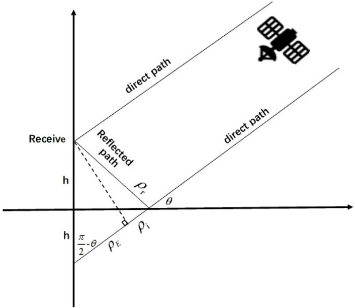
FIGURE 1. Geometric path delay model of GNSS-R altimetry (Yang and Zhang, 2011).
Path delay refers to the distance that the reflected signal experiences more than the direct signal. As shown in Figure 1, the total path delay is: (Katzberg and Garrison, 1997; Yang and Zhang, 2011):
According to the geometric relationship, it can be concluded that: (Yang and Zhang, 2011; Wang et al., 2021):
Where, h represents the height from the receiving platform to the reflecting surface, and θ represents the satellite elevation angle at the mirror reflection point.
GNSS signals propagate through the ionosphere and troposphere in space, resulting in the atmospheric delay. Therefore, the distance relationship between the observed pseudo distance and the actual distance is:
Among them,
Among them,
Among them, the latter two atmospheric delays are the terms that affect the height accuracy of inversion:
Ionospheric Delay Correction
The ionosphere is a dispersive medium in which electromagnetic waves of different frequencies have different propagation paths and velocities. This effect is called ionospheric delay. For GNSS signals, the distance difference of the electromagnetic wave propagation path caused by ionospheric refraction can reach a maximum of 50 m in the vertical gradient direction and 150 m in the horizontal gradient direction (Wang, 2008). According to the A-H (Appleton-Hartree) equation, without considering the higher-order terms, the refraction index of the ionosphere is: (Yuan, 2002; Dong et al., 2018):
Among them,
The phase lead caused by the ionospheric phase path is: (Yuan, 2002):
The code delay caused by the ionospheric group path is: (Yuan, 2002):
The ionosphere contains the most electrons at a distance of 130–500 km from the ground. For the convenience of research, the ionosphere is regarded as a compressed layer 450 km from the ground, which is called the ionospheric single layer model. The intersection point where the GPS signal passes through the model is called the puncture point and the coordinates of this point can be obtained by the following equation: (Liu, 2020):
Among them,
In this work, the GIM (Grid Ionospheric Model) products published by IGS (International GNSS Services) are used to obtain the electron concentration information. The ionospheric grid model divides the space into several grids according to a certain longitude and latitude and the intersection point of each grid is called the ionospheric grid point. At present, IGS divides the world into 5,183 grids according to the longitude from −180°–180° with an interval of 5° and latitude from −87.5°–87.5° with an interval of 2.5°. By interpolating the coordinate values of ionospheric grid points, VTEC at any position can be obtained. Compared with other ionospheric models, GIM can provide a wide range of ionospheric data and is not limited by the environment of the base station. The ionospheric products of the CODE analysis center have high accuracy (Li et al., 2017; Hu et al., 2020b; Liu, 2020), so the ionospheric products provided by CODE is selected for this research. Figure 2 shows the global ionospheric VTEC distribution map obtained from the GIM product provided by CODE at 10:00 on December 3, 2015.
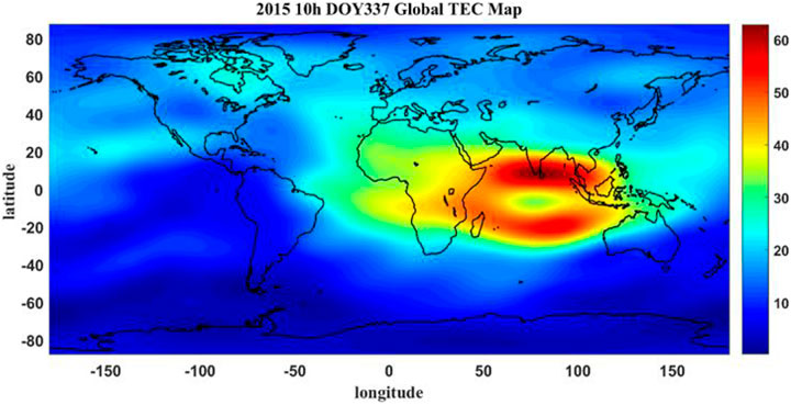
FIGURE 2. Global ionospheric VTEC distribution.
In this work, the IDW (inverse distance weighting) method is used to interpolate the GIM to obtain the ionospheric VTEC value at the puncture point and then the STEC value in the signal path direction is calculated through the geometric relationship to obtain the ionospheric delay in the signal path direction.
The IDW method is based on the distance between the point to be solved and the surrounding known points, to determine the correlation degree between the point to be solved and the known points, to determine the weight coefficient, and to obtain the attribute value of the point to be solved (Wu et al., 2018). The closer the point to be solved is to the known point, the greater the weight. Using the IDW method, the expression of the zenith direction VTEC at the ionospheric puncture point is as follows: (Wu et al., 2018):
Among them,
The value obtained through the above interpolate is the TEC in the zenith direction at the ionospheric puncture point, denoted as VTEC. In the calculation, the TEC along the propagation path of the signal is required, denoted as STEC. Usually, a projection function is used to convert STEC to VTEC. In this experiment, a single-layer projection function is used to convert VTEC to STEC. The projection function is as follows (Liu, 2020):
Among them, ξ represent the angle between VTEC and STEC at the ionospheric puncture point and the other values are consistent with the above.
In this work, we studied the process of the GNSS-R SSH measurement of atmospheric delay influence on measuring precision, and the VTEC at the ionospheric puncture point is obtained by interpolating the GIM production which is provided from IGS, which is then converted into the path direction STEC through the projection function. Finally, the corresponding ionospheric delay is obtained through Eq. 15 (Yuan, 2002).
Tropospheric Delay Correction
From the ground to an altitude of about 60 km is the earth’s atmosphere, of which about 8 km above the ground is the troposphere. When electromagnetic waves pass through the atmosphere, the signal propagation is delayed due to the change of medium density. About 80% of the atmospheric delay occurs in the troposphere, which is called the tropospheric delay. Nikolaidou has pointed out that delay caused by the troposphere is represented by signal velocity delay (linear refraction) and direction bending (angular refraction) (Nikolaidou et al., 2021). In the existing literature, the tropospheric delay for the direct and reflected paths above the receiving platform is offset. Nikolaidou believes this method has certain error defects and ignores the angular refraction delay of signal in space, and this delay will cause an additional atmospheric delay of geometric nature. Nikolaidou creatively analyzed the delay effect caused by signal angular refraction and pointed out that the along-path component and the geometric component must both, be considered in the calculation of tropospheric delay. The equation for the geometric component is as follows: (Nikolaidou et al., 2020a; Nikolaidou et al., 2020b; Nikolaidou, 2020c):
The equation for the along-path component is as follows: (Nikolaidou et al., 2020a; Nikolaidou et al., 2020b; Nikolaidou, 2020c):
Among them,
The equation of the geometric delay component for atmospheric altimetry correction is also given in the literature (Nikolaidou et al., 2021):
This experiment adopted the UNB3m model from the University of New Brunswick to calculate tropospheric delay for along-path component. This model is composed of the Saastamoinen model, Niel mapping function, and annual mean and amplitude table of meteorological parameters. The advantage is that no measured meteorological parameters are needed. The tropospheric delay can be calculated only from the information of altitude, latitude, and annual date.
The calculation equation is as follows, ZHD and ZWD, respectively, represent dry and wet delay of troposphere zenith,
Among them, g represent the acceleration of gravity,
Therefore, the total tropospheric delay is: (Nikolaidou et al., 2021):
When substituting Eq. 22 into Eq. 7, the influence of atmospheric delay on altimetry results can be expressed as:
The last item is the influence value of the geometric component of tropospheric delay on altimetry results, which is consistent with the literature (Nikolaidou, 2020c).
Experimental Data
Airborne GNSS-R Ocean Altimetry Experimental Data
The data were collected from an airborne experiment over the Baltic Sea of Finland by IEEE of Spain on December 3, 2015. During the experiment, the aircraft flew at an altitude of about 3 km and a flight speed of about 50 m/s (Li et al., 2018). The antenna collecting direct signals (RHCP, circularly polarized right hand) pointed to the zenith and the antenna collecting reflected signals (LHCP, circularly polarized left hand) pointed to the ground. The direct signals and reflected signals were obtained by an antenna array of eight components, respectively. The signal is converted down through the RF module to the 35 MHz IF signal and then quantized and stored at a rate of 80 MHz at 1bit, and through the direct signal and reflected signal cross-correlation output one-dimensional delay waveform. The instrument control and data recording system consists of an industrial computer running Linux. The original data recording is turned off when the aircraft turns, and the spectrum analysis of the signals collected during the interval cannot be performed (Ribó et al., 2017).
The airborne experimental data of GPS time was 384702–386364s, and to avoid the impact of the plane turned, the plane turned period of 385121–385542s was removed so only the data of straight flight of the aircraft was selected as the experimental analysis data. The flight trajectory of the aircraft is shown in Figure 3, and PRN1 was selected as the signal source. The elevation angle of the satellite varies from 62.62°–72.30° in this time interval.
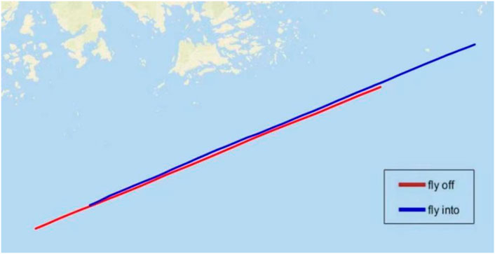
FIGURE 3. Flight trajectory diagram.
Spaceborne GNSS-R Ocean Altimetry Data
The spaceborne data were derived from the products provided by the spaceborne GNSS-R satellite on June 27, 2019, and the satellite orbital altitude was 580 km. The data of different spaceboard platforms in different periods of the day were selected for analysis. The selected data creation time was 3: 33 and 20: 48 UTC on June 27, 2019 of spaceborne A platform and 3: 48 and 21: 03 UTC on June 27, 2019 of spaceborne B platform.
Validated Model
In this work, we adopted the method of DER tracking to obtain the delay of the reflected signal relative to the direct signal, so as to obtain the height h of the receiver platform relative to the reflected surface. After the height H of the platform relative to the reference ellipsoid is known, the SSH was obtained by the following equation:
Due to the lack of measured data, the accuracy of SSH inversion was determined by comparing the inversion with the validation model. In this work, the global mean sea surface model (DTU15 model) explored by the University of Denmark Technical was used as the validation model and compare the SSH inversion of considering the atmospheric delay or not, and to observe the results of atmospheric delay correction.
Results and Discussion
Modified Results of Airborne Experiments
In the experiment of airborne GNSS-R sea surface altimetry, the spatial process of the signal can be divided into three parts. The first part is the path between the GPS satellite and the airborne receiver, which is the direct signal transmission path. During the transmission, the signal through the ionosphere and troposphere suffers from the ionospheric delay and tropospheric delay. The second part is the path between the GPS satellite and the specular reflection point. The signal through the ionosphere and troposphere. The third part is the path of the signal between the airborne receiver and the specular reflection point. As the altitude of the aircraft is only about 3km, the ionospheric delay and tropospheric delay are not considered at this stage.
In this work, the ionospheric delay of each part is calculated by the Klobuchar model and Eq. 15, the tropospheric delay geometric component of each part is calculated by Eq. 16, the tropospheric delay along-path component of each part is calculated by the UNB3m model, we then take the difference between the first part and the second part, and the result is the atmospheric delay experienced during the experiment, which is substituted into Eq. 23 to obtain the influence of atmospheric delay on altimetry results.
Figure 4 shows the atmospheric delay obtained by PRN1 satellite as signal sources. The blue line represents the tropospheric delay, the red line represents the ionospheric delay calculated by the Klobuchar model, and the black line represents the ionospheric delay calculated by the GIM product. Figure 5 shows the atmospheric delay as a function of satellite elevation angle (left) and the relative contribution of the two components to the total delay (right), the red line represents the delay component of along-path, and the black line represents the delay component of the geometric. Figure 6 shows the SSH inversion results of PRN1, the black line represents the SSH provided by the DTU15 model, the red line represents the SSH inversion without considering atmospheric delay, and the blue line represents the SSH inversion which is considering atmospheric delay.
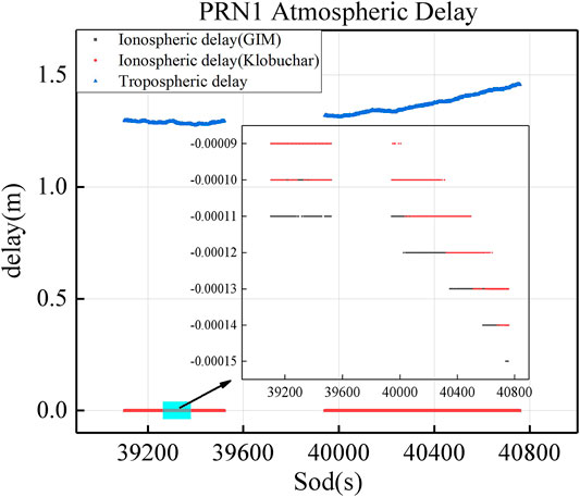
FIGURE 4. Atmospheric delay of PRN1(Blue represent tropospheric delay, red represents the results of the Klobuchar model, and black represent. the results of GIM product).
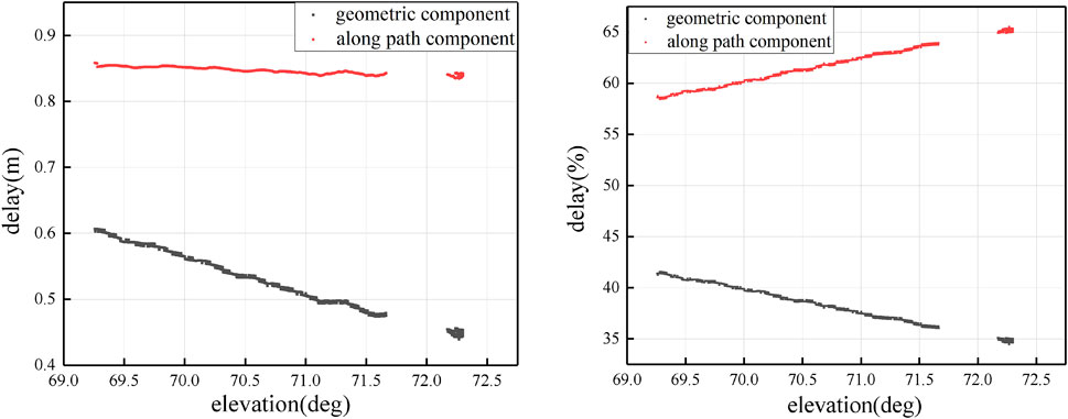
FIGURE 5. atmospheric delay as a function of satellite elevation angle (left), relative contribution of each component to the total (right).
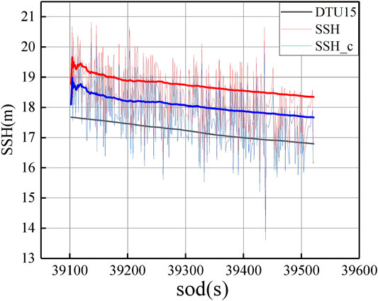
FIGURE 6. Sea surface height inversion results of PRN1.
Modification Results of Spaceborne Experiments
In the spaceborne GNSSS-R altimetry experiment, the transmission path of electromagnetic wave signals is the same as that in the airborne experiment. The difference is that in the spaceborne experiment, since the receiver is carried on a satellite running at a height of 580 km, the direct signals travel only through the ionosphere and are not affected by the troposphere. The reflected signals travel not only through the ionosphere but also through the troposphere. Figure 7 shows the relation between the atmospheric delay by different satellites and the satellite elevation angle at the specular reflection point in the experiments in each period above. The horizontal axis represents SOW (Second of the week), while the vertical axis represents ionospheric delay, tropospheric delay, and satellite elevation angle from top to bottom.
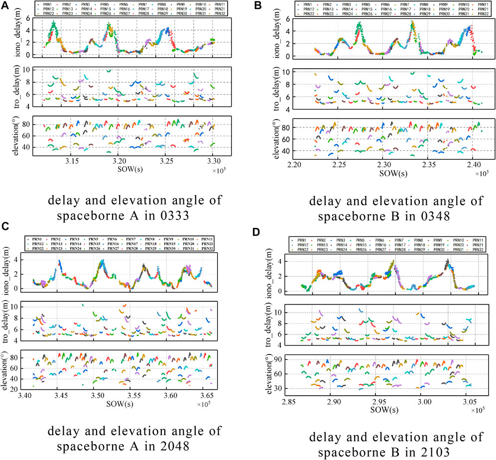
FIGURE 7. Results of spaceborne experimental atmospheric delay: (numbers represent time, the subgraphs are ionospheric delay, tropospheric delay, and specular point elevation angle from top to bottom). Delay and elevation angle of (A) spaceborne A in 0333, (B) spaceborne B in 0348, (C) spaceborne A in 2048, (D) spaceborne B in 2103.
Discussion
By analyzing Figure 4 to Figure 6, it is obvious that in the airborne platform GNSS-R altimetry experiment, the influence of the ionosphere on the altimetry is negligible, while the troposphere has a meter-level delay effect on the signal. At 69.5° elevation angles, the geometric delay component is almost 0.59 m which accounts for 41% of the total delay, the along-path delay component is almost 0.85 m which accounts for 59% of the total delay. At 71.5° elevation angles, the geometric delay component is almost 0.48 m which accounts for 36% of the total delay, the along-path delay component is almost 0.84 m which accounts for 64% of the total delay. And with the increase of the elevation angle, the proportion of the along-path component is increased and the proportion of the geometric component is decreased. The comparison with the DTU15 model shows that the accuracy of SSH inversion is higher after eliminating atmospheric delay error. In this work, mean absolute error (MAE) and Standard Deviations (STD) were taken as the evaluation criteria of the experiment. Meanwhile, Eq. 25 was used to calculate the average value of the influence of tropospheric delay on the altimetry results in this period, which was represented by Mean, the calculation equation is as follows: (Zhang et al., 2021):
Among them,
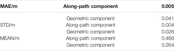
TABLE 1. Results of airborne altimetry experimental data.
For the results of the spaceborne experiment, the elevation angle of the specular reflection point is divided into 10° intervals in this work, and the average value of atmospheric delay on altimetry measurement influence is statistically calculated. The mean value of ionospheric influence is Iono-mean and the mean value of tropospheric influence is Tro-mean. The statistical results are shown in Table 2, and the naming rules are shown as above.
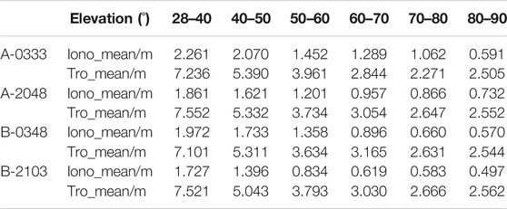
TABLE 2. The average statistical results of the influence of atmospheric delay.
Zhang Qiuyang analyzed the corresponding ionospheric delay measurement values in eight different regions of the world in the spaceborne GNSS-R experiment (Zhang et al., 2020a), and the results showed a meter-level accuracy. Among them, the ionospheric delay at a place close to this experimental site shows a fluctuation of about 6 m. In the experiment, Zhang Yun used the international reference ionospheric model to conduct ionospheric correction on the spaceborne GNSS-R altimetry experiment and the delay error was about 15 m (Zhang et al., 2021). In the experiment of this work, by studying the spaceborne GNSS-R experiment data, it was found that the spaceborne GNSS-R altimetry is greatly affected by the ionosphere and the troposphere, and the order of magnitude results are the same as those in the above literature, which is an error term that must be considered to improve the measurement accuracy. Same as in the airborne experiment, the larger the elevation angle, the smaller the ionospheric delay and the tropospheric delay. As shown in Figure 7, when the elevation angle increases, the error effect caused by the ionosphere and troposphere decreases, the tropospheric delay mainly varies within the range of 4–10 m, and the ionospheric delay is generally less than 6 m. By choosing the suitable elevation angle and correcting the atmospheric delay error, the accuracy of GNSS-R ocean altimetry can be improved by 3∼5 m.
Conclusion
As a new remote sensing measurement technology, GNSS-R has gradually attracted the attention of scholars at home and abroad. Land-based and space-based research and experiments have also achieved remarkable success. However, the research on the spaceborne platform is limited by hardware conditions and there is little research on it at home and abroad. It is not difficult to predict the development prospect of the GNSS-R application on a spaceborne platform. High precision measurement results are the key to the popularization of GNSS-R technology. Electromagnetic waves, as a signal transmission medium, are bound to be affected by the space environment. Therefore, it is necessary to deeply conduct study and exploration on atmospheric delay correction in the signal transmission process.
In this work, the influence of ionosphere and troposphere on the results of GNSS-R altimetry was analyzed by studying the variation of atmospheric delay. Research shows that:
1) In the airborne altimetry experiment, the accuracy of GNSS-R sea surface altimetry measurement can be improved effectively by atmospheric delay correction. Because the airborne platform is too low relative to the ionosphere, the influence of the ionosphere on altimetry can be ignored. The troposphere has a meter-level delay effect on the signal, at 69.5° elevation, the geometric delay component account for 41% of the total delay, the along-path delay component account for 59% of the total delay, at 71.5° elevation, the geometric delay component account for 36% of the total delay, the along-path delay component account for 64% of the total delay. With the decrease of the elevation angle, this effect also decreases. Compared with the DTU15 model, it can be seen that the accuracy of SSH inversion is significantly improved by about 0.7 m after eliminating atmospheric delay.
2) In the spaceborne altimetry experiments, the ionospheric delay and tropospheric delay are both error terms that must be corrected to improve the measurement accuracy. The direct signal is only through the ionosphere above the GNSS-R orbit, not through the troposphere. The reflected signal passes through the entire ionosphere once and the ionosphere below the GNSS-R orbit once, and passes through the troposphere twice. Through calculation, the atmospheric delay error in the spaceborne GNSS-R altimetry fluctuates within the range of 5–16 m and the influence on the altimetry precision is in the range of 3∼5 m.
3) The SSH is a function of elevation angle and the path delay, and the atmospheric delay function is also associated with the elevation angle. Both airborne and spaceborne experiments also show that the atmospheric delay at a high elevation angle is less than that at low elevation angle. Therefore, increasing the altitude cutoff angle of the satellite can effectively improve the data quality in experimental collection.
Data Availability Statement
The original contributions presented in the study are included in the article/Supplementary Material, further inquiries can be directed to the corresponding authors.
Author Contributions
ZY scientific analysis and manuscript writing. WZ and FW experiment design, program management, review, and editing. All authors contributed to the article and approved the submitted version.
Funding
This work was supported by the National Nature Science Foundation of China (41774014, 41574014), the Liaoning Revitalization Talents Program under Grant (XLYC2002082), the Frontier Science and Technology Innovation Project and the Innovation Workstation Project of Science and Technology Commission of the Central Military Commission under Grant (085015), the Outstanding Youth Foundation of the China Academy of Space Technology, and the Independent Research and Development Start-up Fund of Qian Xuesen Laboratory of Space Technology (Y-KC-WY-99-ZY-000-025).
Conflict of Interest
The authors declare that the research was conducted in the absence of any commercial or financial relationships that could be construed as a potential conflict of interest.
Publisher’s Note
All claims expressed in this article are solely those of the authors and do not necessarily represent those of their affiliated organizations, or those of the publisher, the editors and the reviewers. Any product that may be evaluated in this article, or claim that may be made by its manufacturer, is not guaranteed or endorsed by the publisher.
Acknowledgments
We would like to thank the Institute of Space Sciences (ICE, CSIC) and the Institute for Space Studies of Catalonia (IEEC) for providing the raw data processing results of the airborne experiment. We would also like to thank IGS for providing SP3n precise orbit documents and thank CODE for providing the GIM product.
References
Auber, J. C., Bibuat, A., and Rigal, J. M. (1994). “Characterization of Multipath on Land and Sea at GPS Frequencies,” in Proceedings of the 7 th International Technical Meeting of the Satellite Division of the Institute of Navigation, Salt Lake City, September 20-23 1994, 1155–1171.
BelmonteRivas, M., and Martin-Neira, M. (2006). Coherent GPS Reflections from the Sea Surface. IEEE Geosci. Remote Sensing Lett. 3, 28–31. doi:10.1109/lgrs.2005.855617
Camps, A., Park, H., Sekulic, I., and Rius, J. (2017). GNSS-R Altimetry Performance Analysis for the GEROS Experiment on Board the International Space Station. Sensors 17, 1583. doi:10.3390/s17071583
Camps, A., Park, H., Valencia i Domenech, E., Pascual, D., Martin, F., Rius, A., et al. (2014). Optimization and Performance Analysis of Interferometric GNSS-R Altimeters: Application to the PARIS IoD mission. IEEE J. Sel. Top. Appl. Earth Observations Remote Sensing 7, 1436–1451. doi:10.1109/jstars.2014.2320873
Camps, A., ParkFoti, H., Foti, G., and Gommenginger, C. (2016). Ionospheric Effects in GNSS-Reflectometry from Space. IEEE J. Sel. Top. Appl. Earth Observations Remote Sensing 9, 5851–5861. doi:10.1109/jstars.2016.2612542
Caparrini, M., Ruffini, L., and Ruffini, G. C. (2003). “Parfait: GNSS-R Coastal Altimetry,” in The 2003 Workshop on Oceanography with GNSS Reflection, Barcelona, Spain.
Chen, B. (2012). “Ionospheric Tomographic Technology and Applications,”. [master’s thesis] ([ChangSha]: Central South University).
Dong, D., Chen, J., and Wang, J. (2018). GNSS High Precision Positioning Principle. Bei Jing: China Science Publishing &Media Ltd, 40.
Hang, S., Zhang, Y., Li, B., Yang, S., and Han, Y. (2020). Feasibility of Coastal Phase Altimetry Using BeiDOU IGSO Satellite Reflected Signals. Remote Sensing Inf. 35, 73–81. doi:10.3969/j.issn.1000-3177.2020.01.009
Hu, Y., Chen, X., Gu, W., Zhong, L., and Liu, W. (2020a). Research Sea Surface Altimetry Status and Common Methods. GNSS World of China 45, 96–103. doi:10.13442/j.gnss.1008-9268.2020.03.017
Hu, Z., Fan, L., Wang, C., Wang, Z., Shi, C., and Jing, G. (2020b). More Reliable Global Ionospheric Maps Combined from Ionospheric Products of the Seven IGS Analysis Centers. Results Phys. 17, 103162–103797. doi:10.1016/j.rinp.2020.103162
Jin, S., Zhang, Q., and Qian, X. (2017). New Progress and Application Prospects of Global Navigation Satellite System Reflectometry (GNSS+R). Acta Geodaetica et Cartographica Sinica 46, 1389–1398. doi:10.11947/j.AGCS.20170282
Katzberg, S., and Garrison, J. (1997). Utilizing GPS to Determine Ionospheric Delay over the Ocean. Virginia: NASA Langley Technical Report Server.
Katzberg, S. J., and Garrison, J. L. (2001). Surface Reflected Signals from the Global Positioning System for Ionospheric Measurements: Experimental Results at Aircraft Altitudes. Int. J. Remote Sensing 22 (4), 663–689. doi:10.1080/01431160050505919
Leandro, R., Santos, M., and Langley, R. (20062006). UNB Neutral Atmosphere Models Development and Performance. Monterey, California, USA: Proc. IONNTM, Institute of Navigation, 564–573.January 18-20
Li, W., Rius, A., Fabra, F., Cardellach, E., Ribó, S., and Martín-Neira, M. (2018). Revisiting the GNSS-R Waveform Statistics and its Impact on Altimetric Retrievals. IEEE Trans. Geosci. Remote Sensing 56, 2854–2871. doi:10.1109/TGRS.2017.2785343
Li, Z., Wang, N., Li, M., Zhou, K., Yuan, Y., and Yuan, H. (2017). Evaluation and Analysis of the Global Ionospheric TEC Map in the Frame of International GNSS Services. ChineseJ.Geophys. 60, 3718–3729. doi:10.6038/cjg20171003
Liu, h. (2020). “Research on Global Ionospheric Modeling Based on Multi-Source Data Fusion,”. [master’s thesis] (Xi’an: Xi’an University of Science and Technology).
Liu, J., Shao, L., and Zhang, X. (2007). Advances in GNSS-R Studies and Key Technologies. Geomatics Inf. Sci. Wuhan Univ. 32, 955–960.
Liu, Z., Zheng, W., Wu, F., Kang, G., Li, Z., Wang, Q., et al. (2019). Increasing the Number of Sea Surface Reflected Signals Received by GNSS-Reflectometry Altimetry Satellite Using the Nadir Antenna Observation Capability Optimization Method. Remote Sensing 11 (21), 2473. doi:10.3390/rs11212473
Martin-Neira, M. (1993). A Passive Reflectometry and Interferometry System (PARIS): Application to Ocean Altimetry. ESA J. 17, 331–335.
Martin-Neira, M., Caparrini, M., Font-Rossello, J., Lannelongue, S., and Vallmitjana, C. S. (2001). The PARIS Concept: an Experimental Demonstration of Sea Surface Altimetry Using GPS Reflected Signals. IEEE Trans. Geosci. Remote Sensing 39, 142–150. doi:10.1109/36.898676
Martin-Neira, M., D'Addio, S., Buck, C., Floury, N., and Prieto-Cerdeira, R. (2011). The PARIS Ocean Altimeter In-Orbit Demonstrator. IEEE Trans. Geosci. Remote Sensing 49, 2209–2237. doi:10.1109/tgrs.2010.2092431
Nikolaidou, T. (2020c). “Atmospheric Delay Modelling for Ground-Based GNSS Reflectometry,”. PhD dissertation (New Brunswick, Fredericton: Department of Geodesy and Geomatics Engineering, University of New Brunswick).
Nikolaidou, T., Santos, M. C., Williams, S. D. P., and Geremia-Nievinski, F. (2020b). Raytracing Atmospheric Delays in Ground-Based GNSS Reflectometry. J. Geod 94, 68. doi:10.1007/s00190-020-01390-8
Nikolaidou, T., Santos, M., Williams, S. D. P., and Geremia-Nievinski, F. (2020a). A Simplification of Rigorous Atmospheric Raytracing Based on Judicious Rectilinear Paths for Near-Surface GNSS Reflectometry. Earth Planets Space 72, 91. doi:10.1186/s40623-020-01206-1
Nikolaidou, T., Santos, M., Williams, S., and Geremia-Nievinski, F. Preprint (2021) Development and Validation of Comprehensive Closed Formulas for Atmospheric Delay and Altimetry Correction in Ground-Based GNSS-R. doi:10.36227/techrxiv.14345153
Ren, J., Zhang, Q., Jia, H., Liu, J., and Zhang, H. (2018). Research on Development of Space-Based Wide-Swath Imaging Altimetry Technology Systems. Spacecraft Eng. 27, 84–91. doi:10.3969/j.issn.1673-8748.2018.06.012
Ren, X. (2017). “Theory and Methodology of Ionospheric TEC Modelling and Differential Code Biases Estimation with Multi-GNSS,”. [master’s thesis] ([Wuhan]: Wuhan University).
Ribó, S., Arco-Fernández, J., Cardellach, E., Fabra, F., Li, W., Nogués-Correig, O., et al. (2017). A Software-Defined GNSS Reflectometry Recording Receiver with Wide-Bandwidth, Multi-Band Capability and Digital Beam-Forming. Remote Sensing 9, 450. doi:10.3390/rs9050450
Ruffini, G., Caparrini, M., Soulat, F., Martin-Neira, M., Silvestrin, P., and Sharman, K. (2001). Using GNSS Reflections for Ionospheric Studies.
Taoufiq, J., Mourad, B., Rachid, A., and Amory-Mazaudier, C. (2018). Study of Ionospheric Variability Using GNSS Observations. Pos 09, 79–96. doi:10.1236/pos.2018.9400610.4236/pos.2018.94006
Wang, F., Yang, D., Zhang, G., and Zhang, B. (2021). Measurement of Sea Surface Height Using Airborne Global Navigation Satellites System Reflectometry. Acta Aeronautica et Astronautica Sinica, 1–10. doi:10.7527/S1000-6893.2020.24852
Wang, J. (2008). “Monitoring and Application of GNSS Regional Ionospheric TEC,”. [master’s thesis] (BeiJing: Chinese Academy of Surveying and Mapping).
Wu, Y., Guo, C., and W, Y. (2018). “Comparison of Two Interpolation Algorithms in Grid Ionospheric Model,” in The 9th China Satellite Navigation Academic Annual Conference Proceedings - S07 Satellite Navigation Enhancement Technology, Harbin, Heilongjiang, China, May 23-25, 2018. http://www.beidou.gov.cn/zt/dhnh/djjzgwxdhxsnh/.
Yan, Q., and Huang, W. (2016). Retrieval of Ionospheric TEC over Oceans from GNSS-R Delay-Doppler Map. Shanghai, China: MAT/IEEE oceans. doi:10.1109/OCEANSAP.2016.7485349
Yang, D., and Zhang, Q. (2011). GNSS Reflected Signal Processing: Fundamentals and Applications. Bei Jing: Publishing House of Electronics Industry, 129–142.)7-12
Yuan, Y. (2002). “Study on Theories and Methods of Correcting Ionosphere Delay and Monitoring Ionosphere Based on GPS,”. [master’s thesis] ([BeiJing: Chinese Academy of Sciences).
Zhang, Q., Liu, Y., and Xia, J. (2020a). Space-Borne GNSS-R Ionospheric Delay Error Elimination by Optimal Spatial Filtering. Sensors 20, 5535. doi:10.3390/s20195535
Zhang, Y., Ma, D., Meng, W., Zheng, Q., and Yang, S. (2021). Research on Sea Surface Altimetry Mode of GPS Reflected Signal Based on TechDemoSat-1 Satellite. J. Beijing Univ. aeronautics astronautics, 1–13. doi:10.13700/j.bh.1001-5965.2020.0357
Keywords: airborne GNSS-R, spaceborne GNSS-R, atmospheric delay, tropospheric delay, ionospheric delay, global navigation satellite system-reflectometry(GNSS-R) ocean altimetry
Citation: Yan Z, Zheng W, Wu F, Wang C, Zhu H and Xu A (2022) Correction of Atmospheric Delay Error of Airborne and Spaceborne GNSS-R Sea Surface Altimetry. Front. Earth Sci. 10:730551. doi: 10.3389/feart.2022.730551
Received: 25 June 2021; Accepted: 02 February 2022;
Published: 14 March 2022.
Edited by:
Jinyun Guo, Shandong University of Science and Technology, ChinaReviewed by:
Cheng Wang, Beihang University, ChinaThalia Nikolaidou, Department of Natural Resources, Canada
Copyright © 2022 Yan, Zheng, Wu, Wang, Zhu and Xu. This is an open-access article distributed under the terms of the Creative Commons Attribution License (CC BY). The use, distribution or reproduction in other forums is permitted, provided the original author(s) and the copyright owner(s) are credited and that the original publication in this journal is cited, in accordance with accepted academic practice. No use, distribution or reproduction is permitted which does not comply with these terms.
*Correspondence: Wei Zheng, emhlbmd3ZWkxQHF4c2xhYi5jbg==; Fan Wu, d3VmYW5AcXhzbGFiLmNu
†These authors have contributed equally to this work