 Yuqi Ren
 Yang Li
 Xinghai Lei1
- 1School of Energy and Mining Engineering, China University of Mining and Technology-Beijing, Beijing, China
- 2Beijing Tiandi Huatai Mining Management Co. Ltd, Beijing, China
Given the growing popularity of fully mechanized longwall mining, hydraulic shields have emerged as the most crucial pieces of equipment whose rated support capacities are a significant assurance for safe extraction of coal seams. Based on the extraction in the 1,692 panel of the No.9 coal seam in Qianjiaying coal mine, a detailed study of the reasonable shield support capacity under an extremely close goaf was conducted using field measurements, theoretical analyses, and system development. The results show that the ZY4800-13/32 shield employed in the 1,692 panel is unreasonable owing to its large surplus coefficient of support capacity and low support utilization rate. The voussoir beam structure is established for a given load of the loose body to calculate the shield support capacity when the lower coal seam is extracted under an extremely close goaf. The calculated shield support capacity required for the No.9 coal seam was 3,560.03 kN, so the rated support capacity should be 4,000 kN. A calculation and analysis scheme for the shield support capacity under the given load of loose body was developed using a GUI in Matlab, and this scheme was used to examine the influence degrees of the relevant parameters of the immediate roof, main roof, and loose body on the shield support capacity. The thickness of the main roof was found to have the greatest influence on the shield support capacity. Finally, presplitting the main roof was proposed as an effective method for controlling the breaking length and reducing the shield support capacity based on existing research.
1 Introduction
As an important piece of equipment for controlling the ground pressure in the extraction of the coal seam, the hydraulic shield can effectively balance the roof pressure to ensure safe production. This means that the hydraulic shield must have a certain support capacity for the roof pressure (Stanislaw et al., 2016; Stanislaw et al., 2017; Cheng et al., 2018; Marcin and Stanislaw, 2019; Song et al., 2019; Sylwester et al., 2020). The maximum load capacity that a hydraulic shield can bear when acted upon by roof strata is called the rated support capacity, and the actual load capacity that the hydraulic shield can bear is referred to as its actual support capacity (Qian et al., 2010). During the first weighting or periodic weighting, the actual support capacity may exceed the rated support capacity, which can cause shield crushing and roof falling accidents that threaten the workers’ safety. More seriously, the damage to the hydraulic shield can affect the normal production of the panel face. However, when the actual support capacity is less than 85% of the rated support capacity, the load utilization rate of the shield is considered to be low and unable to perform to its full potential. This means that the shield selection is unreasonable, resulting in increased cost per ton of coal. Therefore, determining the rated shield capacity is of great significance for the production of the panel face and even the coal mine (Li et al., 2021a).
At present, the main approaches used to determine the shield support capacity include the empirical estimation, on-site measurement, and voussoir beam structure analysis methods. In the empirical estimation method, the shield support capacity is approximately estimated by the product of 4–8 times of the mining height and bulk density. In the on-site measurement method, a large number of on-site measurement data, including roof-to-floor convergence and periodic weighting interval, are used to establish the initial, average, and final shield support capacities through regression and mathematical-statistical analyses. However, the movement of the roof strata must be considered when determining the shield support capacity. Qian et al. (1996) and Cao et al. (1998) regarded the shield and surrounding rock as an organic whole and analyzed the coupling mechanism of the support and surrounding rock in detail. Wang et al. (2014) and Wang et al. (2015) established the binary criterion and argued that the shield support capacity should balance the roof load as well as maintain the stability of the coal wall. In addition, a new dynamic method to determine the shield support capacity was proposed using theoretical models and field measurements based on the first weighting of the support by the main roof. Wang et al. (2017) and Pang et al. (2020) analyzed the coupling relationship as well as control method for the strength, stiffness, and stability between the support and roof strata in the panel face based on coal seam extraction by the ultra-large-height mining method; a “two-factors” method for determining the shield support capacity was also proposed for ultra-large-height mining. Yan et al. (2011) and Yu et al. (2021) proposed a roof structure called the “short cantilever beam and hinged beam” structure using a new concept and discrimination method for the immediate roof and main roof in extraction by the large-height mining method; the calculation formula for the shield support capacity was also given. Zhang et al. (2021) analyzed the influence of the key stratum position on the shield support capacity for the large-height top-coal caving method. Kong et al. (2021) and Li et al. (2022) studied the roof structure and proposed improvement of the shield support capacity to avoid an unstable face-end roof.
Extant research on the shield support capacity is mostly focused on coal seam extraction using ultra-large- or large-height mining methods. However, there are few studies on the shield support capacity in the extraction of close multiple coal seams, especially those under an extremely close goaf. Studies on extraction of close multiple coal seams have investigated the stability and stress concentration of the pillar left in the goaf, reasonable position, and support scheme of the entry of the lower coal seam (Liu et al., 2016; Li et al., 2020; Sun et al., 2020; Zhang et al., 2020; Feng et al., 2021; Liu, 2013; Wu et al., 2022). Generally, the shield support capacity in coal seam extraction includes the weight of the immediate and force generated by the movement of the blocks by breaking of the main roof. The movement of blocks formed by breaking of the main roof was often simplified to be caused by the uniformly distributed load on the blocks (Qian et al., 2010). However, under the extremely close goaf, the force on the blocks is no longer a uniformly distributed load.
Based on the above findings, a masonry beam structure with a given load of the loose body was proposed for coal seam extraction under an extremely close goaf according to the roof structure characteristics. The movement of blocks formed by breaking of the main roof was considered to be caused by the loose body of gangue in the upper goaf, which is arched. Furthermore, the shield support capacity was obtained by calculation. The rated support capacity in the No.9 coal seam in the Qianjiaying coal mine was calculated, and the rationality of the support selection was analyzed. At the same time, a calculation and analysis scheme of the shield support capacity under a given load of the loose body was developed to analyze the influence degrees of the related parameters of the immediate roof, main roof, and loose body.
2 Case overview
The Kailuan Coal Mine Group’s Qianjiaying coal mine is a typical close multiple coal seam extraction mine, which is located in the Kaiping coalfield in Hebei Province, China. There are five minable coal seams distributed from the top to bottom within the 80 m coal-bearing strata, which are No.5, No.7, No.8, No.9, and No.12 coal seams. Among these, the vertical distance between the No.7, No.8, and No.9 coal seams is only 2–8 m, so these are typical ultra-close coal seams, as shown in Figure 1.
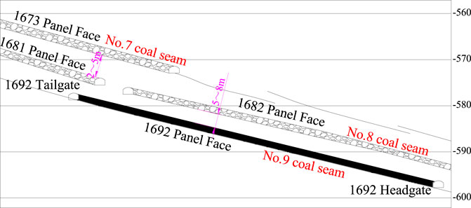
FIGURE 1. Distribution of the ultra-multiple coal seams.
At present, the 1,692 panel face is located in the No.6 district of the No.1 level; the No.9 coal seam is the main mining layer in the 1,692 panel face, with an average thickness of 1.9 m, average inclination angle of 17°, and average burial depth of 468.5–521.5 m. The fully mechanized coal mining method was adopted for this panel face, and the ZY4800-13/32 hydraulic shield was used to control the roof of the panel face. However, the 1,681 and 1,682 panel faces were extracted before the 1,692 panel extraction. The comprehensive column of coal and rock mass in the 1,692 panel is shown in Figure 2.
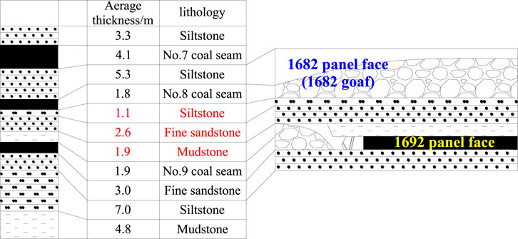
FIGURE 2. Column of rock mass and coal seam.
3 Field measurement of shield support capacity
The ZY4800-13/32 hydraulic shield was employed in the 1,692 panel face based on the production situation and support selection experience, according to its user handbook, as shown in Figure 3. The rated and initial support capacities are 4,800 kN (39 MPa) and 3,877 kN (31.5 MPa), respectively.
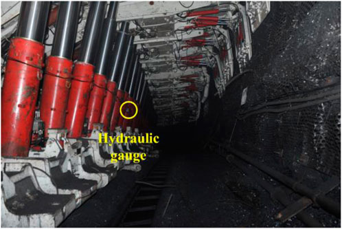
FIGURE 3. ZY4800-13/32 hydraulic shield.
3.1 Field measurement scheme
In the Qianjiaying coal mine, the inclined width of the 1,692 panel face is 160.8 m. From the tailgate to the headgate, there are a total of 107 hydraulic shields in the 1,692 panel face. As shown in Figure 4, a measuring station is arranged every 10 shields in the panel face for a total of 10 stations. The hydraulic gage readings of the left and right columns are recorded through the pressure gages installed on the columns. The average value between the left and right column readings is taken as the actual shield support capacity from field measurements.
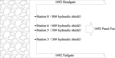
FIGURE 4. Field measurement scheme for the shield support capacity.
3.2 Field measurement results
Figure 5 shows the field measurement results of the shield support capacities at stations 3, 5, 6, and 8. During the field measurements, the 1,692 panel face advanced by a total of 32 m. Table 1 presents the analysis results of the shield support capacity at each station. It is seen from Table 1 that the overall trend of variation of the shield support capacity is similar for each station. The average support capacity measured for the panel face was 16.27 MPa, which is 41.72% of the rated support capacity. During periodic weighting, the maximum support capacity measured was 28.88 MPa, which was 73.85% of the rated support capacity. Therefore, the shield support capacity was generally low (less than 80%). The overall shield support capacity measured for the panel face was thus 6.29–28.88 MPa, with the shield load utilization rate being 16.13–73.85%, indicating a large surplus coefficient of support capacity and low support utilization rate by the 1,692 panel face. Based on the combination of coal mine production situation and shield selection experience, the shield load utilization rate of the ZY4800-13/32 hydraulic shield is not high, which means that the shield selection is unreasonable and can be optimized.
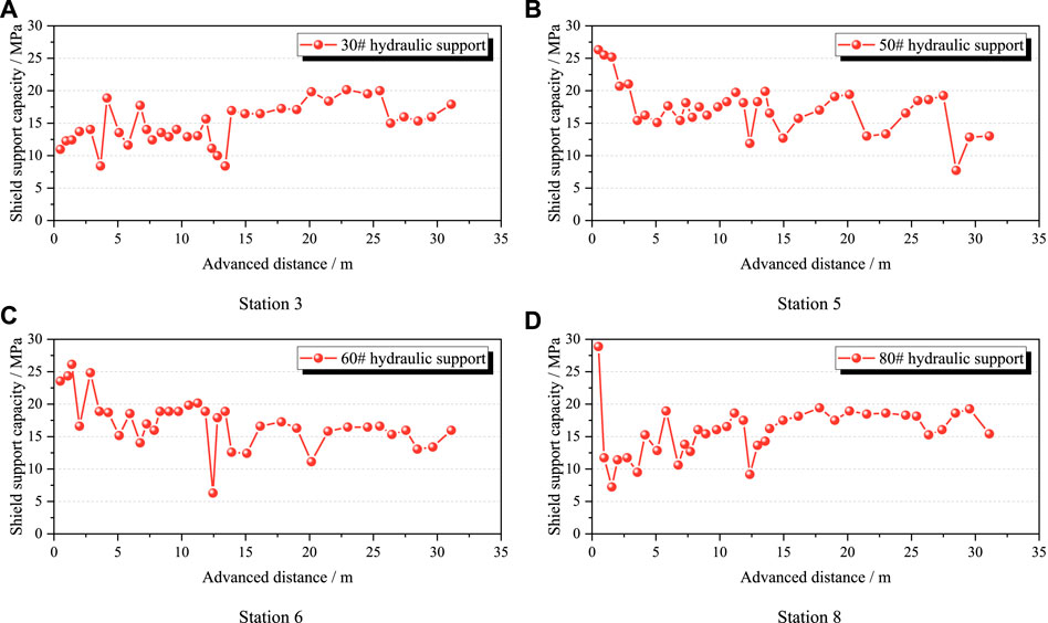
FIGURE 5. Field measurement results of the shield support capacity.
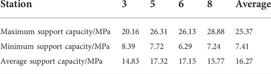
TABLE 1. Maximum, minimum, and average support capacities at each field measurement station.
4 Calculation of shield support capacity
The interactions between the shield and roof strata are the bases of not only ground control but also roof stability testing. At the same time, they provide a reference for reasonable shield selection. Based on the observed results from the 1,692 panel face in the No.9 coal seam using ground penetrating radar and borehole television (Li et al., 2019; Li et al., 2021b; Li et al., 2021c), the roof structure model after coal seam extraction under an extremely close goaf is established. Further, the reasonable shield support capacity for coal seam extraction under an extremely close goaf is calculated.
4.1 Voussoir beam structure with given load of the loose body
The No.9 coal seam is extracted after the No.8 seam; the primary fissures in the roof strata of the No.9 coal seam are relatively developed but have good continuity and integrity. After extraction of the No.8 coal seam, its roof strata break and collapse into the gangue, which is then compacted in the goaf above the roof strata of the No.9 coal seam owing to its weight and loose body state (Li et al., 2008; Zhu et al., 2010). However, with the advancement of the panel face, the roof strata of the No.9 coal seam reach the limit span and may periodically break into rock blocks. The immediate roof of the No.9 coal seam breaks and collapses in the goaf, and the main roof of the No.9 coal seam breaks into articulated blocks; these articulated blocks generated by breaking of the main roof form a stable balance structure called the voussoir beam structure that bears the gangue in the goaf of the No.8 coal seam (Qian et al., 2010), as shown in Figure 6.
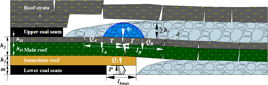
FIGURE 6. Roof structure characteristics after coal seam extraction.
From Figure 6, the interactions between the hydraulic shield and roof strata include the support, cantilever beam of the immediate roof, voussoir beam of the main roof, and the load of the loose body. Therefore, coal seam extraction under an extremely close goaf constitutes the articulated balance structure model of a voussoir beam with a given load of the loose body. The support capacity (P) mainly includes the weight of the immediate roof at the maximum control distance of the shield (Q1) and force acting on the shield when the blocks of the voussoir beam are formed by the main roof slip instability (F), as shown in Eq. 1.
In contrast to the conventional methods of estimating the load generated on the blocks by the breaking of the main roof, this study proposes using a given load of the loose body to estimate the load on the blocks; this means that the load is caused by the gangue above the blocks, which is different from the load applied by the intact strata. The load applied to the main roof by the intact strata (q0) can be calculated using Eq. 2.
where Ei is the elastic modulus of the ith main roof; γi is the bulk density of the ith stratum, kN/m3; hi is the thickness of the ith stratum, m.
4.2 Weight of the immediate roof (Q1)
The weight of the immediate roof at the maximum control distance of the shield (Q1) is calculated using Eq. 3.
where γ1 is the bulk density of the immediate roof, kN/m3; h1 is the thickness of the immediate roof, m; l1 is the length of the immediate roof, m, which can be calculated using Eq. 4.
where lkmax is the maximum control distance of the shield, m; Kf is the allowance coefficient.
4.3 Force acting on the shield when the blocks of the voussoir beam are formed by the main roof slip instability (F)
The force acting on the support shield when the blocks of the voussoir beam are formed by the main roof slip instability mainly include the weight of the blocks, load on the blocks, and friction force of the sliding instability between the blocks. Based on the voussoir beam structure, the force acting on the support when the blocks of the beam are formed by the main roof slip instability is calculated using Eq. 5.
where QA+B includes the weight and load of rock blocks A and B, kN; lA and lB are the respective lengths of rock blocks A and B, m; QA and QB are the respective weight and load of rock blocks A and B, kN; hA and hB are the respective thicknesses of rock blocks A and B, which also constitute the thickness of the main roof, m; Ps is the given load on the rock blocks A and B, kN; δ is the subsidence of rock block B, m; m is the thickness of the coal seam, m; Kp is the bulk factor; φ is the internal friction angle of rock blocks A and B, °; θ is the breaking angle of rock blocks A and B, °.
For the thin strata between the upper and lower coal seams (such as the siltstone stratum above the No.9 coal seam), the breaking length can be simplified on the basis of the following reasons. On the one hand, these may be the immediate floor of the upper coal seam, and fissures may develop owing to extraction of the upper coal seam. On the other hand, their thickness and strength may be less than those of the hard strata above the lower coal seam (such as the fine sandstone stratum of the main roof of the No.9 coal seam); thus, the breaking length of the thin strata would be the same as that of the thick strata ideally. The breaking lengths of rock blocks A and B generated by breaking of the main roof can be calculated using Eq. 6, which is the general equation for calculating the periodic weighting of the main roof.
where l2 is the periodic weighting interval of the main roof, m; h2 is the thickness of the main roof, m; Rt2 is the tensile strength of the main roof, kPa; q is the weight of the main roof, kPa.
The given load on the rock blocks A and B (Ps) can be calculated using Eqs. 7–13. After extraction of the upper coal seam, its roof strata break and collapse into the gangue, which may then be compacted in the goaf above the roof strata of the lower coal seam owing to its weight and loose body state. Above the roof strata of the lower coal seam, the collapsed gangue in the goaf of the upper coal seam is compacted and forms a parabolic loose body structure (Li et al., 2008; Zhu et al., 2010). The loads on rock blocks A and B generated by the breaking of the main roof are considered as the weight of the loose body. The shape of the loose body is simplified ideally as the parabolic shape of a loose arch. Figure 7 shows the simplified diagram of the given load of the loose body.
FIGURE 7. Simplified diagram of the given load of the loose body.
The tangent inclination at point (x0,∑hs) is assumed to be nearly equal to the natural repose angle (α) of the loose body structure. Then, the parabola’s equation is assumed as
At the point (x0,∑hs), Eq. 7 becomes Eq. 8.
At x = x0, the derivative of Eq. 8 is
Hence,
Considering safety, a correction factor Ks is added such that Eq. 7 becomes
The area of the parabolically shaped loose body structure (S) is obtained as
The given load for the parabolic shape of the loose body structure (Ps) is then
where ∑hs is the height of the loose body structure, m; ls is the span of the loose body structure, m; Ks is the correction factor; α is the natural repose angle of the loose body structure, °; γs is the bulk density of the loose body structure, kN/m3.
4.4 Calculation result
Through analyses of the geological and observed data from the 1,692 panel face of the Qianjiaying coal mine, the thickness (h1) and bulk density (γ1) of the immediate roof are 1.9 m and 22 kN/m3, respectively; the thickness (h21), bulk density (γ21), and tensile strength (Rt21) of the main roof are 2.6 m, 24 kN/m3, and 4.8 MPa, respectively; the thickness (h22), bulk density (γ22), and tensile strength (Rt22) of the siltstone above the main roof are 1.1 m, 24 kN/m3, and 5.2 MPa, respectively. The lengths (l2) of siltstone and main roof are the same as the periodic weighting interval of the main roof, which is calculated to be 13.17 m. The internal friction angle (φ) between the blocks generated by the main roof is 28°. The maximum control distance of the shield (lkmax) and allowance coefficient (Kf) are 5.1 m and 1.5, respectively. Thus, the length of the immediate roof (l1) is calculated to be 7.65 m. For the loose body of the collapsed and compacted gangue, the height (∑hs), span (ls), natural repose angle (α), bulk density (γs), and correction factor (Ks) are 5.83 m, 13.17 m, 20°, 20 kN/m3, and 1.1, respectively.
The shield support capacity per unit area for the No.9 coal seam extraction is 2,637.06 kN after applying the above parameters to Eqs. 1–13. Considering the width of the shield as 1.5 m and load utilization coefficient as 0.9, the theoretically calculated result of the rated support capacity is 3,560.03 kN for extraction of the No.9 coal seam. Therefore, by taking the surplus into account, a shield with a rated support capacity of 4,000 kN (32.5 MPa) can be selected to meet the safety production requirements. The shield load utilization rate may then improve to 19.35–88.86% when combined with the field measurement data. The shield load utilization rate of the support is thus greatly improved, with a maximum value of 90%. In summary, the ZY4800-13/32 shield support employed in the 1,692 panel face is unreasonable in that its rated support capacity is too large.
5 Analysis of factors influencing the shield support capacity
From theoretical analysis, it is seen that the shield support capacity mainly bears the weight of the immediate roof at the maximum control distance of the shield as well as the force acting on the shield when the blocks of the voussoir beam are formed by the main roof slip instability. Based on the theoretical calculation equation, a calculation and analysis scheme of the shield support capacity under the given load of the loose body was developed to investigate the influences of the related parameters, including the immediate roof, main roof, and loose body, on the shield support capacity.
5.1 Development of calculation and analysis scheme
From the derived equation, a calculation and analysis scheme of the shield support capacity under the given load of the loose body is developed using the GUI features of Matlab. The proposed scheme mainly consists of three interfaces, namely cover, calculation, and analysis, and has two functions for calculation and analysis of the shield support capacity, as shown in Figure 8. The shield support capacity calculation is simplified, and dynamic data calculation is achieved by the system. In addition, the shield support capacity calculation efficiency is enhanced. The developed scheme effectively guides determination of the shield support capacity during mining production and constitutes a first attempt at an intelligent shield selection construction.
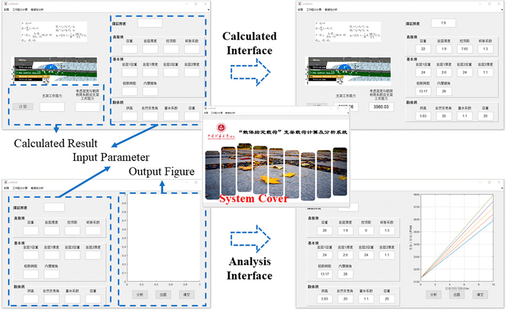
FIGURE 8. Calculation and analysis scheme of the shield support capacity under a given load of the loose body.
5.2 Analysis and discussion
5.2.1 Influences of related parameters of the immediate roof
Figure 9 shows the influences of the bulk density, thickness, and control distance of the immediate roof on the shield support capacity when the parameters of the main roof and loose body are constant. From Figures 9A,B, the shield support capacity is seen to increase as the control distance of the immediate roof increases. Generally, the control distance of the immediate roof is related to the length of the shield top beam. The weight of the immediate roof within the control distance increases as the shield top beam length increases. Therefore, it is necessary to determine a reasonable length of the shield top beam during the shield design process to fully utilize the shield Support characteristics.
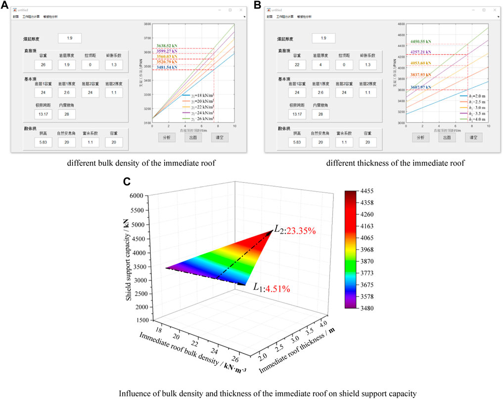
FIGURE 9. Relationship between related parameters of the immediate roof and shield support capacity.
From Figures 9A,B, the shield support capacity is observed to increase with increase in the bulk density and thickness of the immediate roof when its control distance remains constant. However, the bulk density and thickness of the immediate roof have different effects on the shield support capacity, as seen from Figure 9C. When the bulk density of the immediate roof increases from 18 to 26 kN/m3, the shield support capacity increases from 3,481.54 to 3,638.52 kN, which is a 4.51% increase, as shown by L1 in Figure 9C. When the thickness of the immediate roof increases from 2 to 4 m, the shield support capacity increases from 3,607.97 to 4,450.55 kN, which is a 23.35% increase, as shown by L2 in Figure 9C. Obviously, the growth rate of L1 is less than that of L2, i.e., the slope of L1 is less than that of L2. Hence, the thickness of the immediate roof has a greater influence on the shield support capacity than the bulk density.
5.2.2 Influences of related parameters of the main roof
Figure 10 shows the influences of the bulk density, thickness, and limit span of the main roof on the shield support capacity when the parameters of the immediate roof and loose body are constant. From Figures 10A,B, the shield support capacity is seen to increase first and then decrease as the limit span of the main roof increases. Generally, the limit span of the main roof is its periodic weighting interval. From Figure 10A, the limit span of the main roof corresponding to the maximum shield support capacity is observed to be about 10 m where the main roof breaks because of the roof cutting effect of the shield. At this time, the load on the main roof also increases, resulting in accidents, such as shield crushing due to ground pressure behaviors over a large area of the roof. The overburden lithology of coal-bearing strata is determined once it is formed; hence, the thickness of the main roof may change in the strike or tendency of the coal seam. According to Eq. 6, the greater the thickness of the main roof, the greater is its limit span and greater are the blocks generated by breaking of the main roof. Overall, some measures can be adopted to minimize the limit span of the main roof and reduce the chances of accidents by shield crushing, such as presplitting of the hard and thick roof (Wang et al., 2013; Huang et al., 2018; Liu et al., 2019; Chen et al., 2021; Xing et al., 2021).
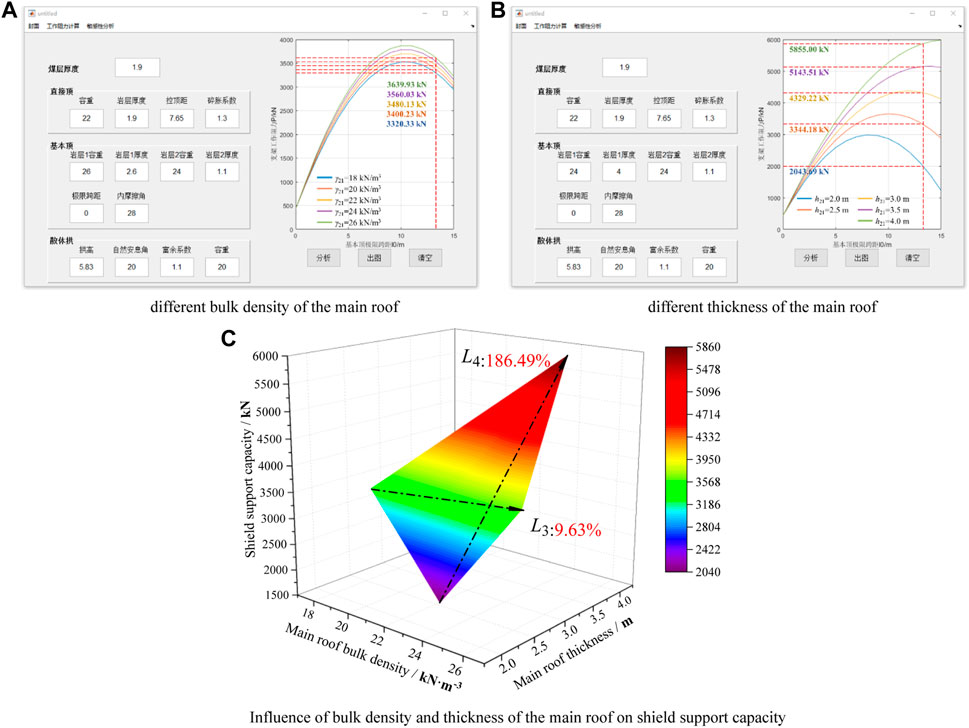
FIGURE 10. Relationship between related parameters of the main roof and shield support capacity.
From Figures 10A,B, the shield support capacity is observed to increase with increases in the bulk density and thickness of the main roof when its limit span remains constant. However, the bulk density and thickness of the main roof have different effects on the shield support capacity, as shown in Figure 10C. When the bulk density of the main roof increases from 18 to 26 kN/m3, the shield support capacity increases from 3,320.33 to 3,639.93 kN, which is a 9.63% increase, as shown by L3 in Figure 10C. When the thickness of the main roof increases from 2 to 4 m, the shield support capacity increases from 2,043.69 to 5,855.00 kN, which is an increase of 180.49%, as shown by L4 in Figure 10C. Obviously, the growth rate of L3 is less than that of L4, i.e., the slope of L3 is less than that of L4. Hence, the thickness of the main roof has a greater influence on the shield support capacity than the bulk density.
5.2.3 Influences of related parameters of the loose body
Figure 11 shows the influences of the bulk density, height, and natural repose angle of the loose body on the shield support capacity when the parameters of the immediate roof and main roof are constant. From Figures 11A,B, the shield support capacity is seen to decrease as the natural repose angle of the loose body increases and increase as the bulk density and height of the loose body increase. Generally, the natural repose angle, bulk density, and height of the loose body formed by the collapsed gangue accumulation in the goaf after extraction of the upper coal seam are related to pressure. When the collapsed gangue in the goaf is gradually compacted under the action of the self-weight and roof load, the natural repose angle and height of the loose body decrease while the bulk density increases.
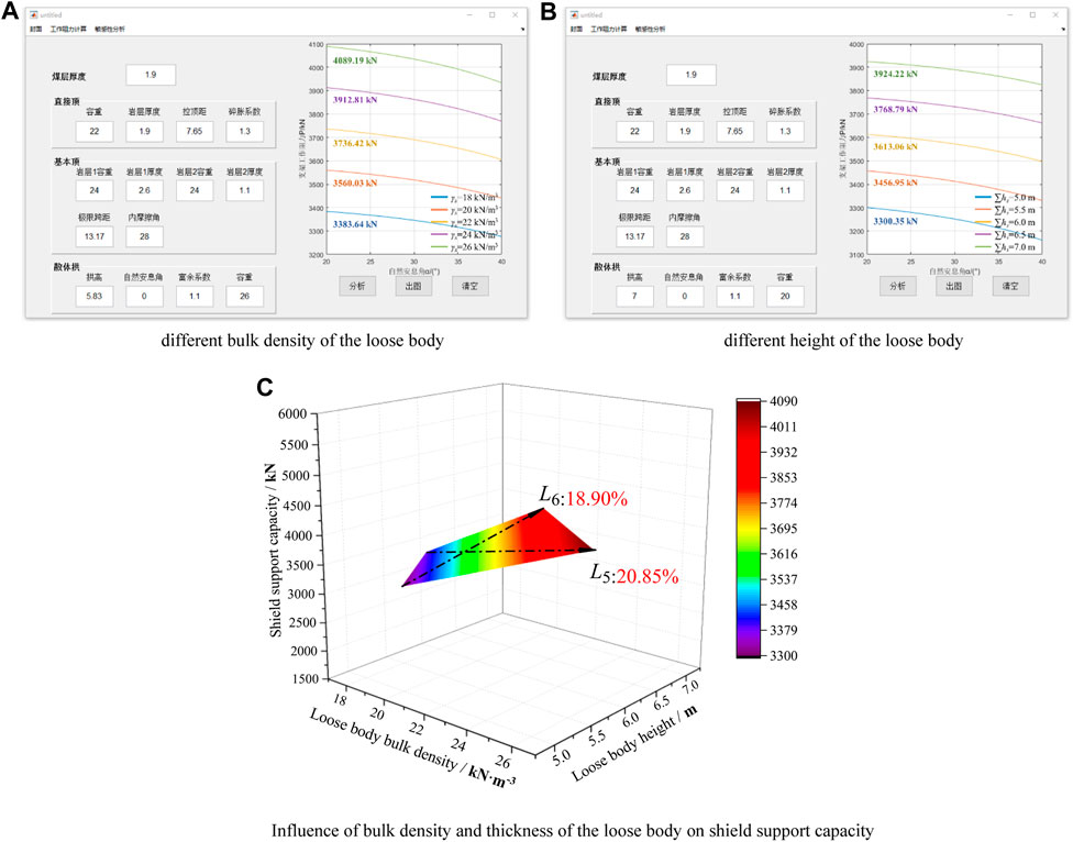
FIGURE 11. Relationship between related parameters of the loose body and shield support capacity.
From Figures 11A,B, the shield support capacity is observed to increase with increasing bulk density and height of the loose body when the natural repose angle remains constant. However, the bulk density and height of the loose body have different effects on the shield support capacity, as shown in Figure 11C. When the bulk density of the loose body increases from 18 to 26 kN/m3, the shield support capacity increases from 3,383.64 to 4,089.19 kN, which is a 20.85% increase, as shown by L5 in Figure 11C. When the height of the loose body increases from 5 to 7 m, the shield support capacity increases from 3,300.35 to 3,924.22 kN, which is an increase of 18.90%, as shown by L6 in Figure 11C. Obviously, the growth rate of L5 is greater than that of L6, i.e., the slope of L5 is greater than that of L6. Hence, the bulk density of the loose body has a greater influence on the shield support capacity than the height.
5.2.4 Discussion
Figure 12 shows the increasing percentage of shield support capacity when the relevant parameters of the immediate roof, main roof, and loose body are changed. It is assumed that the thickness of the main roof significantly influences the shield support capacity when only one parameter is changed and the other parameters are constant. During the initial stage of coal seam extraction under the goaf, the main roof between the goaf and lower coal seam will not break and collapse; as the extraction progresses, the main roof reaches the limit span and breaks into articulated blocks, forming the voussoir beam structure. On the one hand, the hydraulic shield for coal seam extraction under the goaf will bear the self-weight and load on the rock blocks generated by breaking of the main roof. On the other hand, the shield will bear the force of the sliding and instability of the rock blocks. It can be seen from Eqs. 1, 3, and 5 that increasing the thickness of the main roof increases the breaking length. Therefore, the two forces acting on the hydraulic support will also increase, which may cause shield crushing owing to ground pressure behaviors over a large area of the roof. In general, to avoid the occurrences of strong ground pressure behaviors in the panel face from excessive thickness of the main roof, scholars have increasingly conducted research in this field, such as presplitting of the sandstone in the main roof of the Zhangji North coal mine (Ren et al., 2020), deep hole-shaped charge blasting of the hard roof in the Songshuzhen coal mine (Guo et al., 2013), far-field ground fracturing and near-field pressure blasting of the Jurassic and carboniferous coal seam extractions in the Datong mining area (Yu et al., 2019).
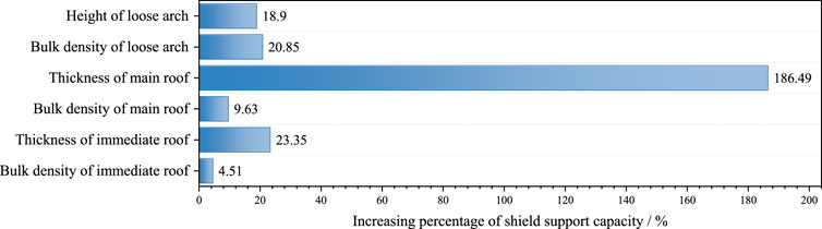
FIGURE 12. Influence degrees of various factors on the shield support capacity.
6 Conclusion
1) Through field measurement and analysis of the shield support capacity of the 1,692 panel face in the No.9 coal seam in the Qianjiaying coal mine, the existing shield selection was determined to be unreasonable. The ZY4800-13/32 shield employed in the 1,692 panel face was calculated to have a large surplus coefficient of the support capacity as well as low support utilization rate.
2) Based on extraction of the No.9 coal seam under an extremely close goaf after extraction of the No.8 coal seam, the voussoir beam structure with a given load of the loose body was established to calculate the shield support capacity. The shield support capacity for the No.9 coal seam was determined as 3,560.03 kN, so a rated support capacity of 4,000 kN should be selected to meet the requirements of production safety.
3) A GUI-based calculation and analysis scheme was developed using Matlab for the shield support capacity under the given load of the loose body. This scheme achieved both dynamic data calculation and improved calculation efficiency of the shield support capacity. The relationship between the support and roof strata was also analyzed visually.
4) Using the proposed calculation and analysis scheme, the influence degrees of the relevant parameters of the immediate roof, main roof, and loose body on the shield support capacity were examined. The thickness of the main roof had the greatest influence of approximately 186.49% increase on the shield support capacity. An increase in the thickness of the main roof resulted in an increase in the breaking length of the main roof; presplitting of the main roof was thus considered to be an effective method of controlling the breaking length to avoid shield crushing due to ground pressure behaviors over a large area of the roof when the load on the shield exceeded the rated support capacity.
Data availability statement
The original contributions presented in the study are included in the article/Supplementary Material, and further inquiries can be directed to the corresponding author.
Author contributions
Conceptualization: YL; data curation: YR, XO, and KY; formal analysis: YR and XO; funding acquisition: YL; investigation: YR, XL, NW, and GL; methodology: YL and YR; system: YR and XO; writing–original draft: YR.
Funding
This research was supported by the National Natural Science Foundation of China (No. 52074293) and the Natural Science Foundation of Hebei Province, China (No. E2020402041).
Acknowledgments
The authors acknowledge the above funds for supporting this research and editors and reviewers for their comments and suggestions.
Conflict of interest
Author KY is employed by Beijing Tiandi Huatai Mining Management Co., Ltd.
The remaining authors declare that the research was conducted in the absence of any commercial or financial relationships that could be construed as a potential conflict of interest.
Publisher’s note
All claims expressed in this article are solely those of the authors and do not necessarily represent those of their affiliated organizations, or those of the publisher, the editors, and the reviewers. Any product that may be evaluated in this article or claim that may be made by its manufacturer is not guaranteed or endorsed by the publisher.
References
Cao, S., Qian, M., Liu, C., and Miao, X. (1998). New Research about Support and Surrounding Rock Relationship in Working Face. J. China Coal Soc. 23 (6), 575–579.
Chen, B., Liu, C., and Wang, B. (2021). A Case Study of the Periodic Fracture Control of a Thick-Hard Roof Based on Deep-Hole Pre-splitting Blasting. Energy Explor. Exploitation, 1–23. doi:10.1177/01445987211036245
Cheng, J., Wan, Z., and Ji, Y. (2018). Shield-roof Interaction in Longwall Panels: Insights from Field Data and Their Application to Ground Control. Adv. Civ. Eng. 2018, 1–18. doi:10.1155/2018/3031714
Feng, G., Wang, S., Guo, Y., Zhang, Y., Bai, J., Niu, L., et al. (2021). Optimum Position of Roadway in the Middle Residual Coal Seam between the Upper and Lower Longwall Gobs. Ene. Sou., Part A: Rec., Util., and Env. Eff., 1–18. doi:10.1080/15567036.2021.1897709
Guo, D., Shang, D., Lv, P., Wang, S., and Wang, J. (2013). Experimental Research of Deep-Hole Cumulative Blasting in Hard Roof Weakening. J. China Coal Soc. 38 (7), 1149–1153. doi:10.13225/j.cnki.jccs.2013.07.021
Huang, B., Cheng, Q., Zhao, X., Xue, W., and Malcolm, S. (2018). Using Hydraulic Fracturing to Control Caving of the Hanging Roof during the Initial Mining Stages in a Longwall Coal Mine: a Case Study. Arab. J. Geosci. 11 (20), 603. doi:10.1007/s12517-018-3969-5
Kong, D., Qiang, Li, Wu, G., and Song, G. (2021). Characteristics and Control Technology of Face-End Roof Leaks Subjected to Repeated Mining in Close-Distance Coal Seams. Bull. Eng. Geol. Environ. 80, 8363–8383. doi:10.1007/s10064-021-02438-5
Li, H., Liu, C., and Wang, L. (2008). Generating and Destabilization Evolutionary of Granular Arch Structure of Upper Immediate Roof. J. China Coal Soc. 33 (4), 378–381.
Li, X., He, W., and Xu, Z. (2020). Study on Law of Overlying Strata Breakage and Migration in Downward Mining of Extremely Close Coal Seams by Physical Similarity Simulation. Adv. Civ. Eng., 1–9 doi:10.1155/2020/2898971
Li, Y., Ren, Y., Wang, N., Luo, J., Li, N., Liu, Y., et al. (2021a). A Novel Mining Method for Longwall Panel Face Passing through Parallel Abandoned Roadways. Shock Vib. 2021, 1–10. doi:10.1155/2021/9998561
Li, Y., Ren, Y., Peng, S. S., Cheng, H., Wang, N., and Luo, J. (2021b). Measurement of Overburden Failure Zones in Close-Multiple Coal Seams Mining. Int. J. Min. Sci. Technol. 31 (8), 43–50. doi:10.1016/j.ijmst.2020.12.009
Li, Y., Ren, Y., Wang, N., Jin, X., Ou, X., Luo, J., et al. (2021c). Structure Form and Evolution Characteristics of Collapsed Roof in Goaf. J. China Coal Soc. 46 (12), 3771–3780. doi:10.13225/j.cnki.jccs.2021.0272
Li, Y., Wang, J., Chen, Y., Wang, Z., and Wang, J. (2019). Overlying Strata Movement with Ground Penetrating Radar Detection in Close-Multiple Coal Seams Mining. Int. J. Distributed Sens. Netw. 15 (8), 155014771986985. doi:10.1177/1550147719869852
Liu, A. (2013). Research on Reasonable Position of Roadway for Close Multi-Seam and its Application. Adv. Mat. Res. 807-809, 2393–2397. doi:10.4028/www.scientific.net/amr.807-809.2393
Liu, H., Jin, D., Jiang, J., Wang, P., and Yang, J. (2019). Analysis of Overburden Structure and Pressure-Relief Effect of Hard Roof Blasting and Cutting. Adv. Civ. Eng., 2019, 1–14. doi:10.1155/2019/1354652
Liu, X., Li, X., and Pan, W. (2016). Analysis on the Floor Stress Distribution and Roadway Position in the Close Distance Coal Seams. Arab. J. Geosci. 9 (2), 83. doi:10.1007/s12517-015-2035-9
Li, Q., Wu, G., Kong, D., Han, S., and Ma, Z. (2022). Study on Mechanism of End Face Roof Leaks Based on Stope Roof Structure Movement under Repeated Mining. Eng. Fail. Anal. 135, 106162. doi:10.1016/j.engfailanal.2022.106162
Marcin, W., and Stanislaw, P. (2019). Numerical Calculations of Shield Support Stress Based on Laboratory Test Results. Comput. Geotechnics 52 (4), 536–546. doi:10.1016/j.compgeo.2015.11.007
Pang, Y., Wang, G., and Yao, Q. (2020). Double-factor Control Method for Calculating Hydraulic Support Working Resistance for Longwall Mining with Large Mining Height. Arab. J. Geosci. 13 (6), 252. doi:10.1007/s12517-020-5208-0
Qian, M., Miao, X., He, F., and Liu, C. (1996). Mechanism of Coupling Effect between Supports in the Workings and the Rocks. J. China Coal Soc. 21 (1), 40–44.
Qian, M., Shi, P., and Xu, J. (2010). Mining Pressure and Strata Control. Xuzhou: China University of Mining and Technology Press.
Ren, S., Zhang, X., Tu, M., Sun, B., and Zhou, T. (2020). Research on Prevention and Control Technology of Strong Mining Pressure in Coal Seam with Thick and Hard Roof. Min. Res. Dev. 40 (9), 81–86. doi:10.13827/j.cnki.kyyk.2020.09.016
Song, G., Ding, K., and Kong, D. (2019). Assessing Longwall Shield-Strata Interaction Using a Physical Model. Q. J. Eng. Geol. Hydrogeology 19 (3), 536–546. doi:10.1144/qjegh2018-174
Stanislaw, P., Marek, P., and Andrzej, W. (2016). Applying the Ground Reaction Curve Concept to the Assessment of Shield Support Performance in Longwall Faces. Arab. J. Geosci. 9 (3), 167. doi:10.1007/s12517-015-2171-2
Stanislaw, P., Sylwester, R., Aleksander, W., and Alicja, K. (2017). Assessment of Roof Fall Risk in Longwall Coal Mines. Int. J. Min. Reclam. Environ. 31 (8), 558–574. doi:10.1080/17480930.2016.1200897
Sun, Z., Wu, Y., Lu, Z., Feng, Y., Chu, X., and Kang, Y. (2020). Stability Analysis and Derived Control Measures for Rock Surrounding a Roadway in a Lower Coal Seam under Concentrated Stress of a Coal Pillar. Shock Vib. 2020, 1–12. doi:10.1155/2020/6624983
Sylwester, R., Tomasz, J., and Stanislaw, P. (2020). Model Tests of the Effect of Active Roof Support on the Working Stability of a Longwall. Comput. Geotechnics 118, 103302. doi:10.1016/j.compgeo.2019.103302
Wang, F., Tu, S., Yuan, Y., Feng, Y., Fang, C., and Tu, H. (2013). Deep-hole Pre-split Blasting Mechanism and its Application for Controlled Roof Caving in Shallow Depth Seams. Int. J. Rock Mech. Min. Sci. 64, 112–121. doi:10.1016/j.ijrmms.2013.08.026
Wang, G., Pang, Y., Li, M., Ma, Y., and Liu, X. (2017). Hydraulic Support and Coal Wall Coupling Relationship in Ultra Large Height Mining Face. J. China Coal Soc. 42 (2), 518–526. doi:10.13225/j.cnki.jccs.2016.0699
Wang, J., Wang, L., and Guo, Y. (2014). Determining the Support Capacity Based on Roof and Coal Wall Control. J. China Coal Soc. 39 (8), 1619–1624. doi:10.13225/j.cnki.jccs.2014.9027
Wang, J., Yang, S., Yang, L., and Wang, Z. (2015). A Dynamic Method to Determine the Supports Capacity in Longwall Coal Mining. Int. J. Min. Reclam. Environ. 29 (4), 277–288. doi:10.1080/17480930.2014.891694
Wu, F., Yu, X., Zhao, G., Du, B., Lv, B., and Zhang, J. (2022). Characteristics of Stress Field and Damage Law of Coal Rock in Residual Pillar of Top Slice and its Application. Front. Earth Sci. (Lausanne). 10, 835531. doi:10.3389/feart.2022.835531
Xing, Y., Huang, B., Li, B., Liu, J., Cai, Q., and Hou, M. (2021). Investigations on the Directional Propagation of Hydraulic Fracture in Hard Roof of Mine: Utilizing a Set of Fractures and the Stress Disturbance of Hydraulic Fracture. Lithosphere 2021 (S1), 4328008. doi:10.2113/2021/4328008
Yan, S., Yi, X., Xu, H., Xu, G., Liu, Q., and Lei, Y. (2011). Roof Structure of Short Cantilever-Articulated Rock Beam and Calculation of Support Resistance in Full-Mechanized Face with Large Mining Height. J. China Coal Soc. 36 (11), 1816–1820. doi:10.13225/j.cnki.jccs.2011.11.022
Yu, B., Gao, R., Kuang, T., Huo, B., and Meng, X. (2019). Engineering Study on Fracturing High-Level Hard Rock Strata by Ground Hydraulic Action. Tunn. Undergr. Space Technol. 86, 156–164. doi:10.1016/j.tust.2019.01.019
Yu, L., Yan, S., and Liu, Q. (2012). Determination of support working resistance of top coal caving in extra thick coal seam. J. China Coal Soc. 37 (5), 737–742. doi:10.13225/j.cnki.jccs.2012.05.018
Zhang, B., Yang, Z., Chunxu, J., Guo, Z., and Li, H. (2021). Research on the Influence of the Key Stratum Position on the Support Working Resistance during Large Mining Height Top-Coal Caving Mining. Adv. Civ. Eng. 2020, 1–9. doi:10.1155/2021/6690280
Zhang, Z., Deng, M., Wang, X., Yu, W., Zhang, F., and Doan, D. V. (2020). Field and Numerical Investigations on the Lower Coal Seam Entry Failure Analysis under the Remnant Pillar. Eng. Fail. Anal. 115, 104638. doi:10.1016/j.engfailanal.2020.104638
Keywords: shield support capacity, multiple coal seams, extremely close goaf, given load of the loose body, system development, influence degree
Citation: Ren Y, Li Y, Lei X, Ou X, Wang N, Li G and Yang K (2022) Theoretical analysis of the reasonable support capacity based on voussoir beam structure for a given load of the loose body under an extremely close goaf. Front. Earth Sci. 10:966660. doi: 10.3389/feart.2022.966660
Received: 11 June 2022; Accepted: 22 July 2022;
Published: 02 September 2022.
Edited by:
Shuren Wang, Henan Polytechnic University, ChinaReviewed by:
Zhijie Zhu, Liaoning Technical University, ChinaYingchun Li, Dalian University of Technology, China
Copyright © 2022 Ren, Li, Lei, Ou, Wang, Li and Yang. This is an open-access article distributed under the terms of the Creative Commons Attribution License (CC BY). The use, distribution or reproduction in other forums is permitted, provided the original author(s) and the copyright owner(s) are credited and that the original publication in this journal is cited, in accordance with accepted academic practice. No use, distribution or reproduction is permitted which does not comply with these terms.
*Correspondence: Yang Li, bGl5YW5nY3VtdGJAMTYzLmNvbQ==