Abstract
To study the risk and control countermeasures of the TBM tunnel construction adjacent to the operational railway tunnel, based on the TBM tunnel project of Chongqing Rail Transit Line 5, this paper first evaluates the quality health degree of the operational tunnel lining (OTL) structure according to the on-site structural inspection. Then, the displacement, internal force, and proximity influence scope influenced by the metro TBM tunnel construction are studied using numerical simulation. Finally, the corresponding control countermeasures are proposed. The results show that: (1) The adjacent construction of the upper TBM tunnel will lead to the uplift deformation trend of the lower operational tunnel, and the uplift deformation of the vault is greater than that of the ballast bed. The influence scope is roughly a parallelogram, with the long axis parallel to the operational tunnel and the short axis parallel to the new TBM subway tunnel. (2) TBM tunnelling over the operational tunnel will cause the transformation of the mechanical mode of the OTL structure from the small eccentric compression mode to the large eccentric compression mode. The OTL structure between the left and right lines of TBM is unfavorable. (3) The longitudinal curve of the bending moment and axial force of the OTL fluctuates greatly within the influence range. The bending moment and axial force are reduced in operational tunnel construction joints. Based on field evaluation and numerical analysis, this paper puts forward some risk control countermeasures, such as TBM tunnelling parameters control, pea-gravel backfilling, backfill grouting, and bottom grouting, which can effectively solve the risk of the operational tunnel structure in the adjacent construction. This study has important reference value for risk control and safety assessment of tunnel in complex adjacent tunnel construction.
1 Introduction
With the rapid development of subway construction in China, more and more subways are constructed adjacent to existing tunnels. Moreover, the construction risk will be further increased when multiple tunnels are constructed close to each other. Being one of the riskiest engineering projects, the adjacent-tunnel construction will lead to adverse effects on the adjacent structures, such as causing cracks in adjacent buildings and threatening the operational safety of existing tunnels (Zhang and Huang, 2014).
Some countries in the world started earlier in adjacent tunnel research, for example, Japan has formed a technical construction guide based on its comprehensive study and summary of various problems on construction adjacent to existing tunnels. In China, Qiu (2003) put forward the definition and classification of the adjacent construction, the theory of adjacent impact zoning, the concept of adjacent, and the corresponding countermeasures; Zheng (2007), Gong (2008), and Kong (2016) continually to conduct in-depth research on the impact degree and impact zoning of different types of adjacent projects. The impact analysis of the construction adjacent to the existing tunnels mainly falls into two groups: the analytical method and numerical simulation. Because of the advantages of low cost, short cycle, repeatability, and suitability for parametric analysis, numerical simulation has been widely used in the research of tunnel adjacent. Li et al. (2016) adopted numerical simulation to analyze the response of deformation, stress, and plastic zone of tunnel intersection. Moreover, the influence scope of the tunnel lining was analyzed, and thus proposed control countermeasures of the locally thickened support structure to improve tunnel stability. Fang et al. (2015) analyzed the settlement of the existing tunnel caused by the new two newly-built shield tunnels by numerical simulation, and used superposition technology to fit the settlement profile of the existing tunnel affected by the new tunnels. Choi and Lee (2010) used numerical simulation method, found that the size of newly-built tunnel, centre spacing of tunnels, and earth pressure coefficient have an influence on the mechanical behaviours of both the existing and new tunnels during construction. Akbari et al. (2020) used numerical method to study the influence of the horizontal distance between the double-line tunnel and the single-line tunnel on the lining deformation, the lining stress, the ground settlement, and the structure stability. It was found that the influence can be ignored when the distance is more than three times the diameter of the single-line tunnel. Jiang et al. (2017) based on the actual project of double tunnels passing through the existing tunnel and found that the adverse effect of the later excavation on the existing tunnel is less than that of the earlier excavation of the tunnel by numerical analysis. It can be seen that, the numerical simulation has become an important research method to analysis the risk of complex tunnel proximity construction, which can provide a basis for risk evaluation and risk control measures.
The risk control measures for proximity construction often adopt the risk control methods such as reinforcing the existing tunnel structure, optimizing the adjacent construction measures, and improving the surrounding rock parameters within the influence area. The safety of the existing tunnel structure can be improved by compensating grouting behind the lining (Zhang et al., 2018). Gauge tie rods, guard rails, and rail fastening beams are usually added to the existing tunnel structure. At the same time, lifting grouting and filling grouting are used to deal with the settlement and the separation between the ballast bed and the tunnel invert (Zhang et al., 2009), to improve the operational safety of the existing tunnel during construction. In addition, measures such as advanced small conduits and surrounding rock grouting reinforcement are taken to improve the strength of surrounding rock between tunnels, which can reduce the tunnel stratum disturbance during the close construction and the impact of new tunnel construction on existing tunnels. Pre-reinforcement measures of pipe shed and pipe curtain (Cui et al., 2022) and temporary invert (Zheng et al., 2009) are adopted to reduce the settlement of existing and new tunnels during the excavation of adjacent tunnels. However, the research on tunnel proximity risk control mainly focuses on construction control measures and structural safety analysis. The research cases of risk analysis and corresponding control measures for TBM tunnelling over the existing tunnels are rarely involved and need to be further studied. Therefore, based on the Chongqing Rail Transit Line 5 tunnel adjacent to the operational railway tunnel project, this paper systematically studies the risk problems and control methods of complex adjacent tunnels through field investigation and numerical simulation.
Based on the project of the Chongqing Rail Transit Line 5 tunnel adjacent to the operational railway tunnel, this paper systematically studies the risk problems and control methods of complex adjacent tunnels through field investigation and numerical analysis. Firstly, the structural safety of the operational tunnel is comprehensively evaluated using on-site inspection. Secondly, the structural displacement, lining internal force, and overall safety of the tunnel complex adjacent-tunnel project are analyzed using numerical analysis. Finally, the influence scope of the TBM tunnelling over the operational railway tunnel is determined, and the corresponding risk control countermeasures are proposed. The research results are of reference value to the risk control and construction safety of complex adjacent projects.
2 Risk control methods of complex adjacent tunnels
2.1 Construction risk
The redistribution of the stress field caused by the construction of a new tunnel will lead to the release of stratum stress in the surrounding area of the tunnel, and the stratum will move toward the new tunnel, which adversely affected the adjacent tunnel structure. The smaller the center distance between adjacent tunnels, the higher the adjacent impact. The elastic-plastic deformation caused by the stress release of the surrounding rock, the compaction deformation caused by the increase of effective earth pressure, and the elastic-plastic and creep deformation caused by the change of soil physical properties (Zheng, 2007) will lead to adverse phenomena of the existing tunnel, such as subsidence, inclination, torsion, structural deformation, etc. The deformation impact of the new tunnel on the existing tunnel is mainly divided into longitudinal deformation and transverse deformation. Transverse deformation shall be detected by bending moment and axial force of lining cross section (Gong, 2008), to prevent torsional deformation during construction. Longitudinal deformation is mainly the lining deformation caused by tunnel settlement or uplift. The longitudinal bending moment plays a decisive role in tunnel cracking, water leakage, and other structural damages (Min et al., 2020).
At the same time, when the existing tunnel has been in service for many years, the state of the tunnel has changed. The construction of the new tunnel may further lead to the change of the structural internal force and the increase of the structural deformation of the existing tunnel. It is difficult to ensure the structural safety of the existing tunnel during construction. According to the classification of the adjacent underground engineering (Qiu, 2003; Guan, 2011), combined with the analysis of burial depth and construction sequence (Boonyarak and Ng, 2014; Islam and Iskander, 2021), the construction risk types of adjacent tunnels are summarized, as shown in Table 1. It can be seen from Table 1 that the construction types of adjacent tunnels can be divided into four categories: parallel, intersection, overlapping, and interlacing. The mechanical model of the intersection type is the longitudinal effect, and the others are the plane models of the lateral effect. Different types of adjacent tunnels face different risks. Parallel tunnels, overlapping tunnels, and interlacing tunnels mainly control the stress redistribution and displacement of surrounding rock caused by excavation, while tunnel crossing is to control the displacement of surrounding rock and existing structural deformation caused by excavation. The uplift deformation of the existing tunnel caused by the parallel tunnel and interlacing tunnel is usually greater than that of the overlapping tunnel. If the distance between the new tunnel and the existing tunnel is fixed, the influence of large-diameter tunnel excavation on the existing tunnel is greater than that of small-diameter excavation (Liang et al., 2021).
TABLE 1
| Type | Mechanical model | Influence factor | Mechanical characteristic | |
|---|---|---|---|---|
| Burial depth | Construction sequence | |||
 | Plane model of lateral effect | With the increase in burial depth, the ground settlement will be smaller and the settlement trough will be wider | When the tunnel is excavated at the same time, the surface settlement has the greatest impact | The surrounding rock around the existing tunnel is relaxed, and the lining load increases, causing tensile deformation to the new tunnel |
 | Plane model of longitudinal effect | As the buried depth of existing tunnels and new tunnels increases, the settlement of existing tunnels due to the new tunnels excavated below decreases. When the new tunnel is above, the uplift of the existing tunnel increases with the increase of C/D* | The vertical displacement of the existing tunnel caused by the excavation of the new tunnel below is far greater than that of the new tunnel above | When the new tunnel is above, the existing tunnel will deform upward due to unloading. When the new tunnel is under, the existing tunnel will continue to sink with the excavation |
 | Plane model of lateral effect | The greater the burial depth, the smaller the surface settlement | The new tunnel above will usually cause the uplift of the lower tunnel. When the new tunnel is below, the existing tunnel will settle due to interaction | When the new tunnel is above, the existing tunnel will deform upward, the arching effect of surrounding rock will be damaged. When the new tunnel is below, the existing tunnel will continue to sink with the excavation |
 | Plane model of lateral effect | The first construction of the upper tunnel will lead to higher ground settlement than the first construction of the lower tunnel | The surrounding rock around the existing tunnel is relaxed, and the lining load increases, causing tensile deformation to the new tunnel | |
Types and influence factors of adjacent tunnels.
*C is the coverage depth of the new tunnel from the ground, D is the diameter of tunnel.
This paper relied on the adjacent project of Chongqing Rail Transit Line 5 which belongs to the construction of new subway tunnels close to the operational railway tunnels. Two parallel TBM tunnels are passing through the two operational tunnels, which belong to the adjacent problem of multiple tunnels. The minimum vertical net distance between the new TBM tunnels and the operational Chongqing-Huaihua Railway tunnels is 8.946 m. The small tunnel spacing can cause a great impact on the operational tunnel, and the construction difficulty is high (Zhen et al., 2019). The distance between the edges of the left and right lines of the subway section is 14 m, and the construction load superimposed on the left and right lines will cause structural damage to the operational railway tunnel. In addition, the stress reorganization caused by the simultaneous excavation of double tunnels may lead to an increase in the settlement of the tunnel (Do et al., 2014). At the same time, the Chongqing-Huaihua Railway Tunnel has been in service for many years, and the safety state of the structure has changed. The construction of the subway TBM tunnels will cause further changes in structural internal force and structural deformation of the existing tunnel. It is difficult to ensure the structural safety and operational safety of existing tunnels during the construction period.
2.2 Risk control methods
At present, the risk assessment method for proximity tunnel construction is not particularly perfect, especially in the field of the complex adjacent tunnel (N.H. Krishnan, 2000). With the wide application of computers, digital technology has been gradually applied to the field of tunnel evaluation, and intelligent tunnel construction has been started for underground projects. I. Yamaguchi and Kiritani. (1998) proposed a safety assessment system and the analytical expression of the ground performance during the adjacent construction. Li and Yuan (2012) used an automatic measurement system to monitor the displacement changes of existing tunnels caused by new tunnels at different crossing stages in real time and provided some ideas for evaluating the influence of shield tunneling on existing tunnels. The subway intelligent deformation prediction model proposed by Qiu et al. (2012) can realize intelligent, automatic deformation measurement, and early warning during the construction process, which can ensure the operational and structural safety of existing tunnels during construction. Clarke and Laefer (2014) proposed a comprehensive risk assessment method and a pre-construction risk assessment procedure for underground projects. Azadi et al. (2013) combined the finite element method and neural network method to assess the risk of the proximity tunnel construction but did not make more detailed planning for the proximity construction. Zheng et al. (2018) evaluated the influence of the new tunnel excavation on the deformation of the adjacent lateral tunnels from the aspects of the excavation depth, the horizontal displacement of the support structure, and the relative tunnel position. Luo et al. (2019) comprehensively analyzed the risk factors that have a greater impact on the construction of the new tunnel under crossing the existing tunnel and established the safety risk evaluation index system and safety risk evaluation model. The risk treatment idea proposed by Lei et al. (2018) is to first find out the key control indicators of the project for an evaluation, then propose the risk control measures and analyze the feasibility by numerical simulation, and finally obtain a complete risk control scheme. Mou et al. (2020) gave the influence area of overlapping tunnels based on surrounding rock parameters, and the transverse and longitudinal effects of orthogonal excavation tunnels, which provides a basis for subsequent construction risk control measures. The analysis method proposed by Zhang et al. (2019) and Liu et al. (2021) can predict the potential risk of new tunnel excavation on existing tunnel, and study the impact of the new tunnel construction on existing tunnel, including longitudinal shear stiffness, volume loss, gap between two tunnels, and the relative stiffness coefficient of surrounding rock.
The main purpose of risk control in the construction of adjacent tunnels is to build new tunnels without affecting the structural stability and operational safety of existing tunnels. The measures to control the influence of TBM tunnel adjacent construction can be divided into active control measures and passive control measures (Hua, 2008). Passive control countermeasures are taken from the perspective of protecting existing tunnels, including changing construction parameters such as tunnelling speed, jack thrust, grouting time, and shield posture (Zhang, 2018), as well as multiple construction parts, short footage, and precision blasting (Zhou et al., 2017), isolation of impacts and other measures. Active control measures are taken to reduce the disturbance of surrounding rock caused by tunnelling, including surrounding rock grouting (Liu et al., 2022), compensation grouting (Gan et al., 2022), and stratum reinforcement. It is a common method to take preventive measures for existing tunnels, which can be divided into basic measures, maintenance measures, and strengthening measures. Among them, strengthening existing tunnels to improve the bearing capacity of the structure has a significant effect, which is one of the common methods to control adjacent construction risks. The risk control of complex adjacent tunnels is a systematic project. It is necessary to take targeted control countermeasures for the protection of existing tunnel structures and reduction of the impact of adjacent construction according to the adjacent tunnel types and risks of the actual engineering project.
Based on the structural inspection and assessment of existing tunnel structures, this paper proposes the risk control method for complex adjacent tunnels. The analysis method mainly includes the structural inspection, assessment of existing tunnels, the optimization design of the tunnel construction, the analysis of the interaction forces under adjacent construction, and the safety impact zoning. The risk control process of TBM tunnel construction is shown in Figure 1. First of all, conduct a structural inspection on the lining thickness, concrete strength, defects behind the lining, lining cracks, and surrounding rock state of the existing tunnel, to obtain the health status of the existing tunnel. Then, conduct the safety and risk analysis on the complex adjacent tunnels, mainly including the influence of tunnel face spacing, the displacement and internal force of the existing tunnel structure, and the longitudinal internal force of the existing tunnel lining after the adjacent construction. According to the analysis results, specific measures of risk control are proposed, such as tunnelling parameters, pea-gravel backfilling, backfill grouting, consolidation grouting at the bottom of segments, and other measures.
FIGURE 1

Risk control process of adjacent tunnel construction.
3 Engineering background
3.1 Project overview
The section tunnel between Renhechang Station and Xingfu Square Station of Chongqing Rail Transit Line 5 starts from Renhechang Station and goes westward along Jinkai Avenue, and then crosses successively above 2# construction inclined shaft of Shanghai-Chengdu Railway, Renhechang Tunnel of Shanghai-Chengdu Railway, Xinrenhechang Tunnel of Chongqing-Huaihua downward line and Renhechang Tunnel of Chongqing-Huaihua upward line. The geographical location and tunnel layout of this line is shown in Figure 2.
FIGURE 2
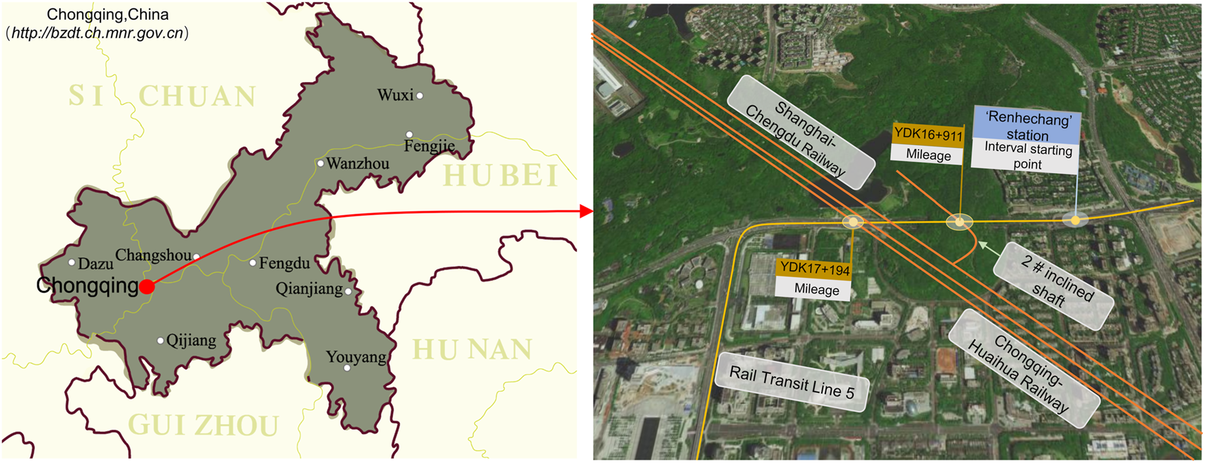
Location plan of the adjacent tunnel.
The mileage range of the section where the section tunnel of Chongqing Rail Transit Line 5 crosses above the Chongqing-Huaihua Railway tunnel is YDK16+911.681 ∼ YDK17+194.572, in a total length of the section is 282.9 m. The tunnel is constructed with a single shield TBM. The lining is Type II (ordinary type), the waterproof concrete is C50, and the impermeability grade is P12. The lining section of the new TBM tunnel is shown in Figure 3A. The designed running speed of the Xinrenhechang tunnel of the Chongqing-Huaihua downward line is 120 km/h. The starting and ending mileage is K12+796 ∼ DK17+567. The surrounding rock of the adjacent area is Grade IV, and the concrete strength grade is C25 corrosion-resistant concrete. The starting and ending operational mileage of the Renhechang tunnel of the Chongqing-Huaihua upward line is K12+765 ∼ DK17+499. The surrounding rock of the adjacent tunnel is Grade IV, and the concrete strength grade is C20 corrosion-resistant concrete. The lining section of the operational tunnel is shown in Figure 3B.
FIGURE 3

Schematic diagram of adjacent tunnel lining section. (A) TBM subway tunnel. (B) Upward operational tunnel.
The original landform of the complex adjacent tunnel section of Chongqing Metro belongs to the tectonic denudation hilly area, with gentle terrain and small undulation, and the gradient is generally less than 5°. The ground elevation along the line is 290∼375, and the relative elevation difference is about 85 m. The exposed strata along the whole line are relatively simple, basically in the Quaternary Holocene loose soil layer and the Jurassic Middle Shaximiao Formation bedrock of continental river lake clastic deposits, mainly composed of sandy mudstone and sandstone. The stratum where the tunnel is located is mainly artificial fill and silty clay. The thickness of the soil layer varies greatly. The bedrock is continental clastic rock with sandstone and mudstone interbedding. The hydrogeological conditions are simple. The groundwater in the site is mainly perched water and bedrock weathering fissure water. The water content in rock and soil layers is generally weak. The profile of the complex adjacent section of Chongqing Rail Transit Line 5 is shown in Figure 4.
FIGURE 4

Profile and stratum distribution of adjacent tunnel.
3.2 Complex adjacent situations
The newly-built Chongqing Rail Transit Line 5 crosses above the Renhechang tunnels of the Chongqing-Huaihua Railway upward line and downward line. The right-line tunnel of the subway intersects with the Chongqing-Huaihua Railway downward tunnel at DK14+803, at a clear distance of 10.743 m, and intersects with the Chongqing-Huaihua Railway upward tunnel at DK14+786, in a clear distance of 10.69 m; the left line tunnel of the subway intersects DK14+831 of Chongqing-Huaihua Railway downward tunnel in a clear distance of 8.946 m, and DK14+758 of Chongqing-Huaihua Railway upward tunnel in a clear distance of 11.944 m. The specific adjacent spatial relationship is shown in Figure 5. The corresponding mileage range of complex adjacent tunnels of Chongqing Metro is shown in Table 2.
FIGURE 5
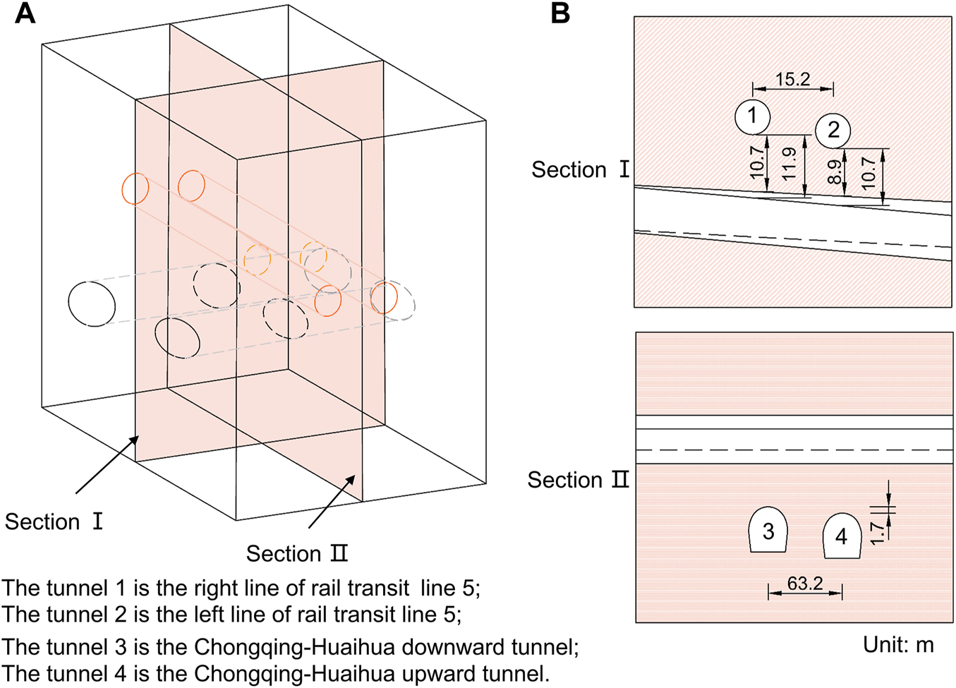
Spatial position relationship of the complex adjacent tunnel. (A) Overall schematic diagram. (B) Section diagram.
TABLE 2
| Clear distance (m) | Intersection mileage | included angle (°) | ||||
|---|---|---|---|---|---|---|
| Right line | Left line | Right line | Left line | Right line | Left line | |
| Chongqing-Huaihua Downward | 10.743 | 8.946 | Mileage: DK14+803 Tunnel signpost: 2+008 | Mileage: DK14+831 Tunnel signpost: 2+036 | 35.4 | 35.4 |
| Chongqing-Huaihua Upward | 11.944 | 10.69 | Mileage: DK14+758 Tunnel signpost: 1+908 | Mileage: DK14+786 Tunnel signpost: 1+936 | 35.4 | 35.4 |
Data sheet of adjacent tunnel.
3.3 Inspection of the operational tunnels
The TBM tunnel construction of Chongqing Rail Transit Line 5 will cause the stress redistribution of the surrounding rock, which will change the longitudinal and transverse internal forces of the operational tunnels, thus affecting the safety of the tunnel structure. In this paper, the health monitoring of the operational Renhechang railway tunnel structures is conducted to understand the structural performance of the operational tunnel structures. To further ensure the structural integrity and operational safety of the existing tunnels. The monitoring instruments include ground penetrating radar (SIR-3000), concrete rebound instrument (ZC3-A), laser profiler (BJSD-2E), core drilling machine (DZ47-63), and ultrasonic detector (NM-4A). The monitoring technology adopted in this paper is based on TB10417-2003, 2003, TB10223-2004, 2004, TB/T 2820.1-1997, 1997 and Railway transport letter, 2004.
The soundness rating table of the Renhechang tunnels of the Chongqing-Huaihua railway is shown in Table 3. There are fourteen voids behind the lining of the operational upward tunnel inspection section. The voids with a cumulative length of 30 m account for 5.5% of the total length of the upward line inspection section. The spacing of the steel bars in the secondary lining is 21∼25 cm, and the spacing of the steel frames in the primary support is 1.2 m. Among the twelve tested sections, intrusion in the design clearance is found in eleven sections, accounting for 91.7%, and the maximum intrusion clearance is 5.95 cm. Only one section is found with intrusion into the tunnel construction clearance, accounting for 8.3%, and the intrusion value is 0.51 cm. In all sections, no intrusion is found within the basic construction clearance. The monitoring shows that the tunnel lining has the following diseases: six cracks (two at the arch waist and four at the arch foot, including four oblique cracks), one longitudinal construction gap joint with water leakage, and one circumferential crack. The surrounding rock within 29∼45 cm behind the support is relatively broken, and the wave velocity of rock mass is 2.82∼3.55 km/s.
TABLE 3
| Lining | Detection results | Rating | Comprehensive assessment | Remarks | ||||
|---|---|---|---|---|---|---|---|---|
| Upline | Downline | Upline | Downline | Upline | Downline | Upline | Downline | |
| Thickness | > δ | > δ | 0 | 0 | 1 | 1 | ||
| Concrete strength | :40.8 MPa > fcu,k(c25) | :21.5 MPa < fcu,k(c25) | 0 | 1 | 1 | |||
| Defects behind lining | Length:1∼3 m | Length < 3 m width>1.5 mm | 1 | 1 | 1 | 1 | ||
| Cracking | Length < 7 m width < 2 mm | Length < 3 m width < 1.5 mm | 1 | 1 | 1 | 1 | ||
| Surrouding rock | Joint fissures (small range) | Joint fissures (small range) | 0 | 0 | ||||
Soundness rating form of operational tunnels of Chongqing-Huaihua railway.
Note: 1) δ indicates design thickness of lining; 2) indicates detection value of concrete strength; fcu,k indicates the design strength; 3) 0 indicates minor impact, 1 indicates slight impact.
There are twenty-three voids behind the lining of the operational downward tunnel inspection section. The voids with a cumulative length of 48 m account for 7.3% of the total length of the downward line inspection section. There are steel bars in the secondary lining, with a spacing of 20∼24 cm. There are steel frames in the primary support, and the spacing of some steel frames is 1.0 m. Among the twelve tested sections, eleven sections (91.7%) are found with intrusion in the design clearance. The maximum intrusion clearance is 3.7 cm. No intrusion is found within the tunnel construction clearance or the basic construction clearance. The monitoring shows that the tunnel lining has the following diseases: four cracks (three at the vault and one at the arch foot, including one diagonal crack), one longitudinal crack, and two circumferential cracks, and all cracks have no water leakage. The surrounding rock behind the left wall is complete, and the surrounding rock within 77∼114 cm behind the right wall is relatively broken, with a rock wave velocity of 3.06∼3.11 km/s.
4 Numerical simulation
4.1 Numerical model
This paper uses the FLAC 3D finite-difference program for numerical simulation. The three-dimensional spatial relationship of adjacent tunnel groups is simulated through fine modeling, and the stress response and lining deformation are calculated to analyze the safety risks. According to the actual project situation, the longitudinal length of the model is 330m, the transverse length is 240m, and the depth under the invert of the tunnel is 60 m. The tunnel construction process is simulated according to the actual project. The front, back, left and right edges of the model are subject to horizontal constraints, the bottom boundary is subject to vertical constraints, and the top boundary is a free plane. The stratum and initial support are simulated by the elastic-plastic element, and the secondary lining is simulated by Liner structural element. The numerical calculation model is shown in Figure 6A. The adjacent tunnel model is shown in Figure 6B.
FIGURE 6
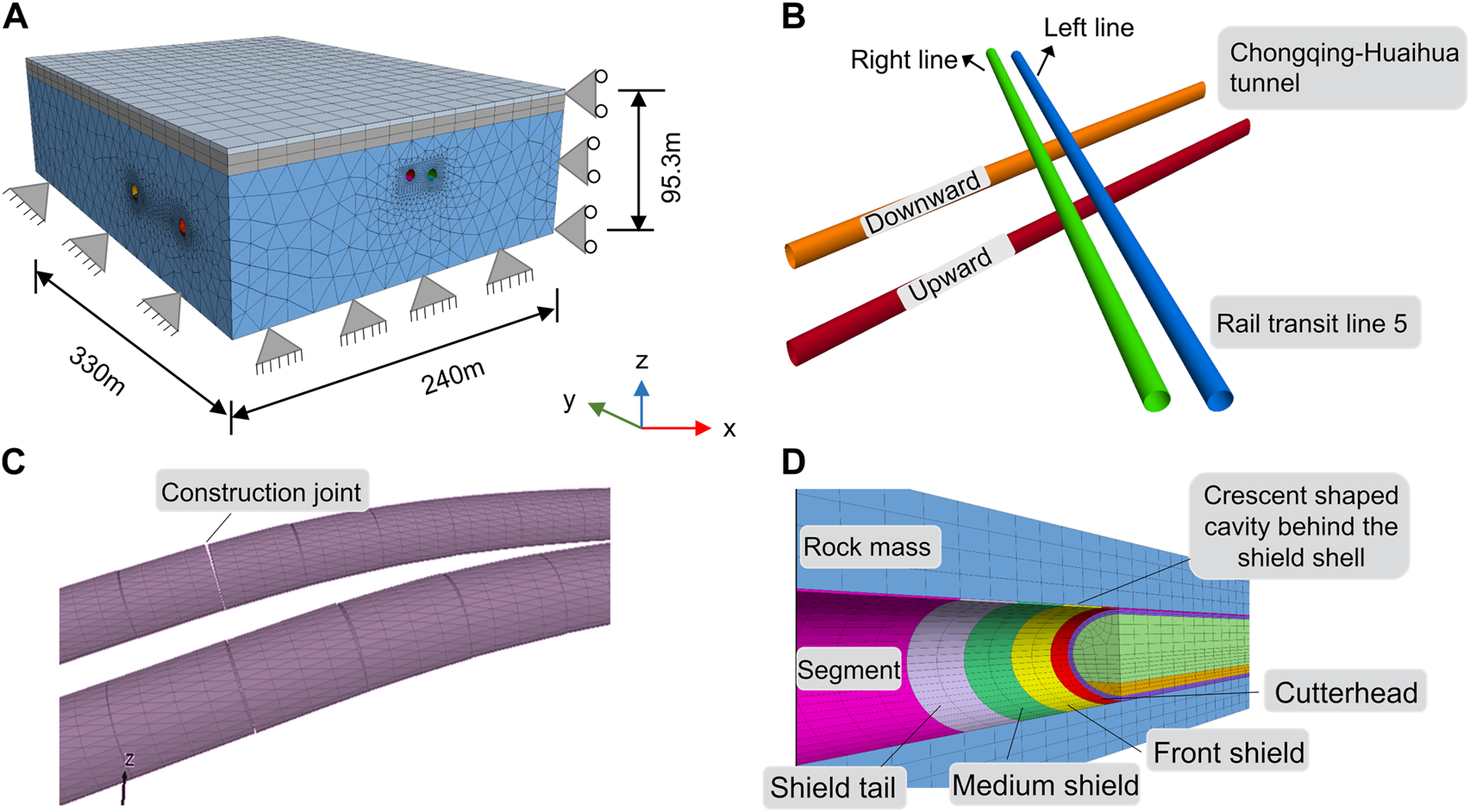
Numerical model. (A) Overall model. (B) Adjacent tunnel. (C) Lining construction joint. (D) TBM tunneling construction.
Geological parameters in the numerical simulation are determined according to the Geotechnical Investigation Report of Chongqing Rail Transit Line 5. The mechanical parameters of each stratum are shown in Table 4. Physical parameters of the lining are according to TB 10003-2005, 2005. The detailed mechanical parameters are shown in Table 5. Considering that the waterproof board is laid between the initial support and the secondary lining, the model achieves the effect of sliding by setting the contact surface parameters. Considering the construction joint setting of the secondary lining during the calculation, the secondary lining of the operational railway tunnel is set with a ring of construction joints every 9 m along the longitudinal direction. The construction joint is realized by changing the link between the liner. The parameters of the contact element are shown in Table 6. The simulation of the construction joint is shown in Figure 6C. The construction steps of the TBM tunnel are determined by reference to the construction design data. Figure 6D shows the TBM tunnel excavation and segment construction. To simulate the TBM tunnel construction, the first step is TBM tunnelling, then activating the shell element of the shield shell, releasing 70% of the load on the tunnel face and 30% of the load on the radial direction of the tunnel, and the simulation calculation is carried out until the balance is achieved. Then, the segments shall be constructed at the tail of the shield, and the crescent-shaped cavities behind the segments shall be backfilled. After that, the calculation is conducted until the balance is achieved, and the next construction cycle is carried out.
TABLE 4
| Category | γ (kN/m3) | E (MPa) | μ | c (KPa) | φ (°) |
|---|---|---|---|---|---|
| Plain fill | 21.0 | 500 | 0.3 | 40 | 28.0 |
| Sandy mudstone 1# | 25.6 | 1660 | 0.36 | 750 | 33.3 |
| Sandy mudstone 2# | 25.6 | 1738 | 0.36 | 900 | 33.9 |
Mechanical parameters of geotechnical materials.
TABLE 5
| Concrete | γ (KN/m3) | E (GPa) | μ |
|---|---|---|---|
| Primary lining | 22 | 20.0 | 0.2 |
| Secondary Lining of Chongqing-Huaihua Upward | 25 | 28.0 | 0.2 |
| Segment | 25 | 25.0* | 0.2 |
| Shield shell of the shield machine | — | 210.0 | 0.2 |
Mechanical parameters of support materials.
*Consider stiffness reduction.
TABLE 6
| Name | c (MPa) | φ (°) | t (MPa) | kN (N/m3) | ks (N/m3) |
|---|---|---|---|---|---|
| Contact face | 0.001 | 1.0 | 0.001 | 15e10 | 15e10 |
Calculation parameters of the contact surface.
4.2 Weight distribution parameters of TBM
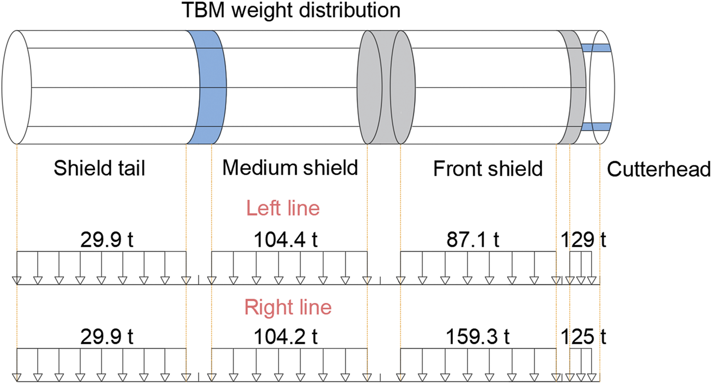
TBM is a large mechanical equipment, and the influence of TBM’s heavy weight on the tunnel structure shall be considered. TBM weight distribution shall be determined according to the construction design data as shown in Table 7, and TBM weight distribution in the numerical calculation is shown in Figure 7.
TABLE 7
| Type | Cutterhead | Front shield | Medium shield | Shield tail |
|---|---|---|---|---|
| TBM337(Single shield) | 12712 | 8297 | 6356 | 1989 |
| TBM338(Single shield) | 12809 | 4517 | 5356 | 1741 |
TBM weight distribution (kg).
FIGURE 7
TBM tunnel weight distribution.
4.3 Measurement schemes
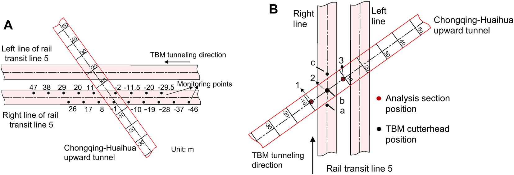
To analyze the influence of adjacent tunnel construction on lining internal force and structural deformation of the operational tunnel, this paper analyzes the influence of TBM tunnel cutterhead position on lining internal force and structural deformation of different sections of an operational railway tunnel in the construction process. Figure 8 shows the layout of measuring points for structural impact analysis of the operational tunnel. The intersection point between the right line of the new tunnel and the central axis of the operational upward tunnel is 0. Figure 8A shows the layout of monitoring points for the longitudinal displacement of the operational upward tunnel structure during TBM tunnelling, that is, when the TBM working face reaches the set point, the longitudinal displacement of the operational tunnel is extracted once. The numbers in the figure represent the distance from the TBM face position to point 0. A negative value indicates that it has not yet passed through the centerline intersection, while a positive value indicates that it has passed through the centerline intersection. Figure 8B shows the structural monitoring section layout of the operational tunnel at different positions of the TBM cutterhead. Wherein, points a, b, and c represent the position of the TBM tunnel cutterhead and points a and c are −6.87 m and 7.6 m away from point b, respectively. Points 1, 2, and 3 represent different sections of the operational tunnel. Points 1 and 3 are −9.02 m and 9.02 m away from the section of point 0, respectively.
FIGURE 8
Layout of monitoring points of the operational tunnel. (A) Displacement monitoring. (B) Internal force monitoring.
4.4 Longitudinal spacing of TBM tunnel face
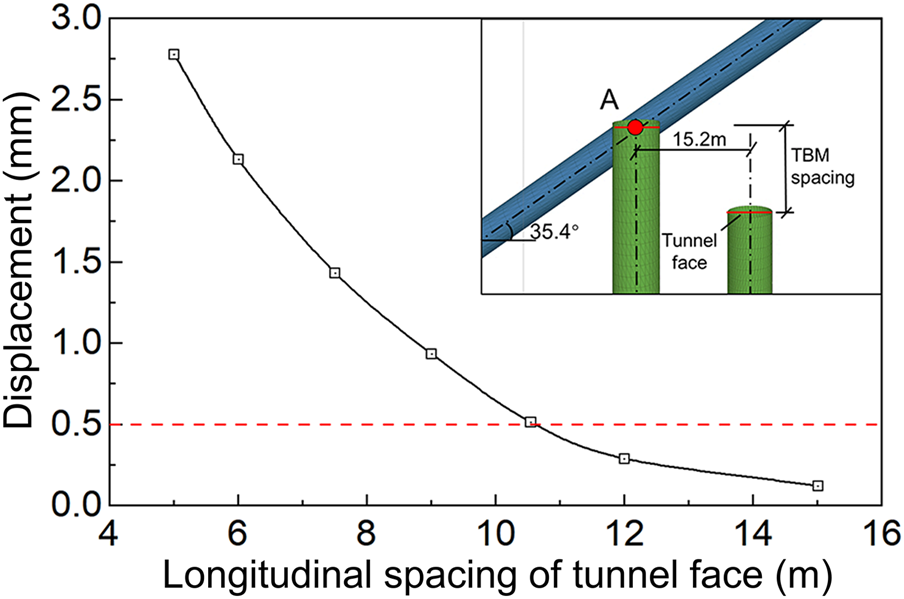
To analyze the influence of TBM tunnel face spacing of the TBM tunnel on the deformation of the operational tunnel structure during tunnel adjacent construction, the right line of the TBM tunnel is excavated above the centre line of the operational railway tunnel, and then the left line tunnel is excavated, with footage of 1.5 m. The distance between the centerline of the double tracks of the TBM tunnel is 15.2 m. During the construction, the vertical displacement of the ballast bed at the intersection of the operational railway tunnel was monitored. By analyzing the influence of the tunnel face distance on the deformation of the operational tunnel structure, the minimum distance between the new TBM tunnel faces during the excavation is determined.
Figure 9 shows the influence curve of different distances of tunnel face on the displacement of the operational tunnel ballast bed during the TBM tunnelling. It can be seen that when the tunnel face spacing of the TBM tunnel decreases from 16 m to 4m, the displacement of the operational tunnel ballast bed increases from 0.116mm to 2.78 mm. Based on the previous geological data, operational tunnel structural detection, and the experience of the railway administration, the deformation of the operational railway tunnel ballast bed caused by subway tunnel excavation shall not exceed 0.5 mm. According to the numerical simulation results, when the TBM tunnel face spacing of Rail Transit Line 5 is 10 m, the vertical displacement of the ballast bed near the tunnel intersection reaches 0.5 mm. The double-line subway construction will have a superposition effect on the deformation of the operational railway structure. Therefore, the minimum longitudinal spacing (safety spacing) of the TBM tunnel face during the tunnelling of the new subway tunnel is determined as 15.0 m.
FIGURE 9
Curve of influence of different distances of tunnel face on the displacement of tunnel ballast bed of operational tunnel during TBM tunneling.
5 Results and discussion
5.1 Effect of longitudinal displacement of the operational tunnel
By simulating the actual construction process of the TBM subway tunnels, an analysis is done here on the displacement changes in the vault and ballast bed structure of the operational railway tunnel at different TBM tunnel face positions. The evaluation of the displacement impact of the operational tunnel lining and its influence scope was also analyzed. Considering that the two operational tunnels affected by the TBM tunnel have similar adjacent influence rules, only the up-line operational tunnel is selected for analysis in this paper. The analysis scope covers the right line of the new tunnel from 46 m outside the intersection to 26 m across the intersection. The displacement of the operational tunnel is recorded every 9 m of tunnelling.
The vault displacement curve of the operational tunnel changes in the process of TBM tunnel excavation is shown in Figure 10A. The analysis scope is from - 46m to 26 m from the intersection of the right line of the new TBM tunnel, and the longitudinal displacement of the operational tunnel is recorded every 9 m of TBM tunnelling. The longitudinal displacement analysis length of the operational tunnel is 100 m. The vault displacement of the operational tunnel at the monitoring point shows an overall upward trend. At first, when the TBM tunnel face was −46 m from the intersection, the influence scope of displacement of the operational tunnel was only between −30 m and −9 m, with an affected length of about 22 m long. When the excavation is near the intersection, the operational tunnel will heave longitudinally from −38 m to 26 m, with an affected length of 64 m. The maximum vault displacement of the operational tunnel is 1.032 mm. In the process of TBM tunnelling from far to near toward the intersection, the affected area of the operational tunnel shows a multiple growth trend. The tunnel uplift displacement increases significantly, and the displacement change curve gradually changes from gentle to steep. Because of the certain included angle between the TBM tunnel and the operational tunnel, with the tunnelling of the TBM tunnel, the displacement of the tunnel vault on the left side of the intersection (along the tunnelling direction) first appears to uplift. As the TBM face approaches the tunnel intersection, more parts of the operational tunnel are affected by proximity, and the uplift displacement increases accordingly. When the tunnel face of the right TBM tunnel crosses the intersection by 17m, the left TBM tunnel is just above the center line of the operational tunnel, and the displacement change of the operational tunnel reaches the peak value. In addition, with the TBM tunnelling, the peak displacement points of the vault have a trend of changing from left to right. The vault displacement of the operational tunnel is respectively −16 m, −14 m, −9 m, −8 m, −5 m, −0.8 m, 5 m, 5.3 m, and 5.3 m.
FIGURE 10
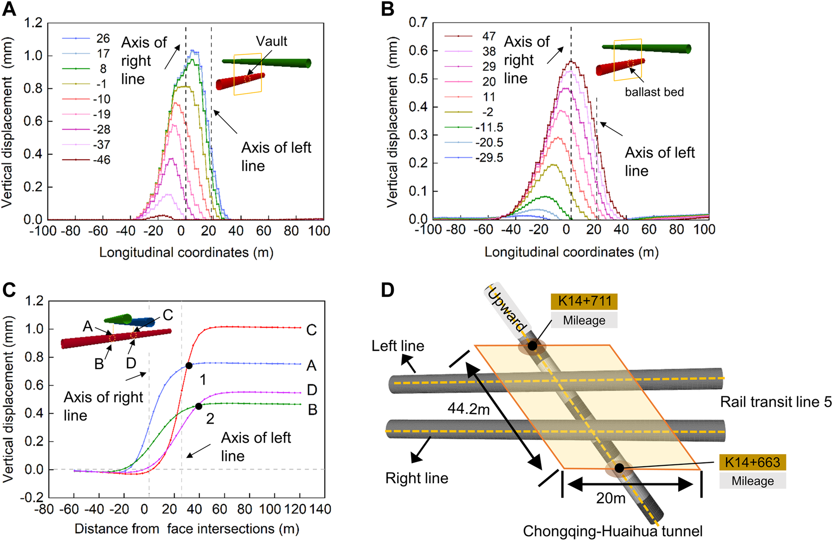
Displacement curve and influence scope of the operational tunnel. (A) Vault. (B) Ballast bed. (C) Cross section. (D) Influence area.
The ballast bed displacement curve of the operational tunnel changing with the TBM tunnel excavation is shown in Figure 10B. The analysis scope is from −29.5 m to 47 m from the intersection of the right line of the new TBM tunnel, and the longitudinal displacement of the operational tunnel is recorded every 9 m of TBM tunnelling. The longitudinal displacement analysis length of the operational tunnel is 100 m. The maximum displacement of the ballast bed of the operational tunnel is 0.56mm, which is 0.472 mm smaller than the maximum displacement of the vault. As a whole, the displacement change of the ballast bed is smaller than that of the vault.
The displacement change curve of the vault and ballast bed at the intersection of the operational tunnel and the new tunnel is shown in Figure 10C. Points A and B are the displacement monitoring points of the vault and the ballast bed, respectively, at the intersection of the operational tunnel and the new right-line tunnel. Points C and D are the displacement monitoring points of the vault and ballast bed, respectively, at the intersection of the new left-line tunnel and the operational tunnel. The maximum uplift of two points A and B of the new right line tunnel are 0.76 mm and 0.47 mm respectively, and the displacement tends to be stable 40 m after the TBM tunnel face crosses the intersection. The maximum uplift of C and D points of the new left line tunnel is 1.02 and 0.55 mm respectively, and the displacement tends to be stable at 57.5 m after the TBM face crosses the intersection. The displacement of point D lags behind that of points A and B, mainly because the TBM tunnel face of the right line is 15 m ahead of the left line.
As shown in Figure 10C, when the TBM face of the right line tunnel reaches the intersection (0 m), the displacement of points A and B are 0.29 mm and 0.15 mm, respectively, and the value is greater than that of points C and D. When the new left line is driven to the intersection of the left line and the operational tunnel (29.2 m), the displacement curves of points A and C intersect at point 1 at this time, and then the displacement curves of points B and D also intersect at point 2. Take intersection point 1 as an example, the displacement at the intersection of A and C at point 1 is 0.75 mm, and the displacement at point A reaches the peak value and keeps stable. However, the displacement change of the left line intersection is continuing until the TBM left line tunnel crosses the left line intersection by 31.7 m and then tends to be stable.
As mentioned in the previous section 4.4, the displacement of the operational tunnel ballast bed caused by subway tunnel excavation shall not exceed 0.5 mm. Combined with the displacement data and the actual field data, the influence scope of the tunnel is obtained, as shown in Figure 10D. The mileage of the influence area of the operational tunnel is between K14+663 and K14+711, and the whole influence area is roughly a parallelogram. The long axis is 44.2 m parallel to the operational tunnel, and the short axis is 20 m parallel to the new subway tunnel.
5.2 Effect of internal force of operational tunnel lining cross-section
The disturbance caused by the TBM tunnelling will have a certain impact on the stress of the operational tunnel structure. This section analyzes the internal force changes of the operational tunnel lining when TBM is excavated near the intersection and the TBM cutterhead is far away from the intersection. The variation law of the internal force of the operational tunnel lining is analyzed, and the safety factor of the lining structure is calculated.
Figure 11 A, B, and C show the distribution of the bending moment and axial force of the lining in Section 1, Section 2, and Section 3 in the operational tunnel when the TBM cutterhead excavates in positions a, b, and c of the right line, respectively. On the whole, when the TBM cutterhead is at points a, b, and c, the distribution laws of bending moment, axial force, and safety factor of the operational tunnel are similar, and the changes of bending moment and axial force of Section 1, Section 2, and Section 3 are not significant. Among them, the bending moment is relatively small at the vault, left and right side walls, and invert arch; contrarily, the bending moment is relatively large at the left and right arch waists and the left and right wall feet, showing a ‘butterfly-like’ distribution characteristics. For the axial force, the minimum axial force is at the vault and the maximum is at the invert. From the vault to the inverted arch, the axial force increases gradually, and the axial force presents the ‘apple-like’ distribution characteristics. For the safety factor, the safety factor of the left arch waist is the largest, the vault is the smallest. For the right arch waist, when the TBM cutterhead is located at points a and b, the safety factor is sorted from large to small as Section 3 > Section 2 > Section 1; when the TBM cutterhead is at point c, the safety factor of the left arch waist of Section 1 is the largest, followed by Section 2, and finally Section 3. In the process of TBM tunnelling from point a to point c, the safety factors of all parts of Section 3 gradually decrease, especially the left and right arch waists, where the safety factors of the left arch waists decrease by about 20% and the right arch waists decrease by about 60%. The main reason is that Section 3 locates between the left and right TBM tunnels, within the cross-influence range, and is greatly affected by the adjacent construction.
FIGURE 11

Bending moment, axial force, and safety factor of sections 1, 2, and 3. (A) The cutterhead is at point a. (B) The cutterhead is at point b. (C) The cutterhead is at point c.
The summary of the structural stress in Section 2 when the TBM tunnel face is located at a, b, c, and after the TBM tunnel face crosses the intersection for a long distance is shown in Table 8. The maximum positive bending moment of tunnel lining is inside the vault, the maximum negative bending moment is outside the arch foot, and the maximum axial force is at the invert. When the TBM cutterhead is close to the intersection, the bending moment increases. When it crosses the intersection and starts to move away, the bending moment decreases. Similar change laws can also be found in axial force. After the TBM tunnel face is far away from the intersection, the bending moment and axial force of the existing lining are finally stable (See data at position d in Table 8), and their values are the same as those of the cutterhead at position c.
TABLE 8
| Location | Part | M (kN·m) | N (kN) | e0/h* | Eccentric compression mode | Safety factor |
|---|---|---|---|---|---|---|
| a | Vault | 5.99 | −13.07 | 1.528 | Large | 12.530 |
| Left arch waist | 4.43 | −35.26 | 0.419 | Large | 55.549 | |
| Right arch waist | 5.96 | −34.00 | 0.584 | Large | 29.451 | |
| Left wall foot | 3.45 | −91.86 | 0.125 | Small | 42.399 | |
| Right wall foot | 2.24 | −91.46 | 0.082 | Small | 47.244 | |
| Left inverted arch | 2.32 | −99.73 | 0.078 | Small | 43.776 | |
| Right inverted arch | 2.13 | −99.33 | 0.071 | Small | 44.639 | |
| b | Vault | 6.22 | −12.73 | 1.629 | Large | 11.740 |
| Left arch waist | 3.83 | −35.39 | 0.361 | Large | 68.826 | |
| Right arch waist | 7.04 | −34.11 | 0.688 | Large | 20.226 | |
| Left wall foot | 4.00 | −93.21 | 0.143 | Small | 40.160 | |
| Right wall foot | 2.73 | −97.88 | 0.093 | Small | 42.922 | |
| Left inverted arch | 2.12 | −102.06 | 0.069 | Small | 43.697 | |
| Right inverted arch | 2.47 | −102.05 | 0.081 | Small | 42.443 | |
| c | Vault | 5.47 | 13.31 | 1.370 | Large | 14.460 |
| Left arch waist | 3.43 | 35.17 | 0.325 | Small | 76.249 | |
| Right arch waist | 6.81 | 33.06 | 0.687 | Large | 20.960 | |
| Left wall foot | 5.13 | 85.18 | 0.201 | Small | 39.043 | |
| Right wall foot | 3.54 | 88.70 | 0.133 | Small | 43.143 | |
| Left inverted arch | 1.74 | 98.47 | 0.059 | Small | 46.538 | |
| Right inverted arch | 2.60 | 97.31 | 0.089 | Small | 43.590 | |
| d** | Vault | 5.63 | 13.33 | 1.408 | Large | 13.856 |
| Left arch waist | 3.29 | 35.27 | 0.311 | Small | 77.747 | |
| Right arch waist | 6.94 | 33.53 | 0.690 | Large | 20.445 | |
| Left wall foot | 5.08 | 85.38 | 0.198 | Small | 39.135 | |
| Right wall foot | 3.46 | 89.35 | 0.129 | Small | 43.209 | |
| Left inverted arch | 1.72 | 98.16 | 0.058 | Small | 46.747 | |
| Right inverted arch | 2.63 | 96.91 | 0.090 | Small | 43.619 |
Summary of structural stress of Section 2
*e0 represents the eccentricity; h represents the thickness of lining cross-section.
**Position d refers to location of the TBM, tunnel face crosses the intersection for a long distance.
It can also be seen from the internal force in Table 8 that the left arch waist of Section 2 is in the large eccentric compression mode when the TBM cutterhead is at a and b positions. When the TBM tunnel crosses the intersection point, it changes to the small eccentric compression mode again and then keeps the small eccentric compression mode unchanged. It shows that the TBM tunnel construction above the operational tunnel will change the local stress mode of the lining structure, and the lining structure will have a local tension trend. Moreover, the displacement change results of the vault and ballast bed of the operational tunnel in Section 5.1 also show that the uplift displacement of the vault is greater than that of the ballast bed. The lining structure shows a tensile trend in the vertical direction. Therefore, corresponding risk control measures should be taken to ensure the safety of the operational tunnel structure during the construction of the TBM tunnel up-crossing the operational tunnel.
5.3 Longitudinal influence of the internal force of operational tunnel lining
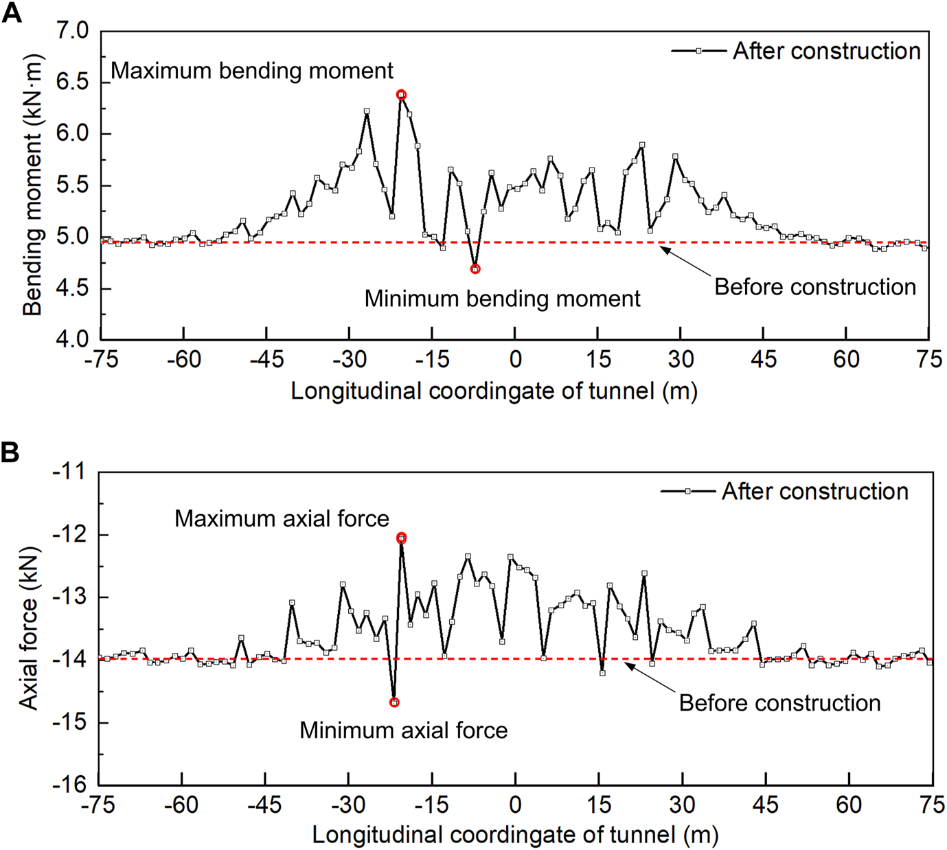
To study the internal force changes of the operational tunnel lining after the adjacent construction, this paper analyzes the longitudinal bending moment and axial force changes of the tunnel lining when the tunnel face of the TBM tunnel is located directly above the tunnel crossing point. Figure 12 shows the longitudinal curves of the bending moment and axial force at the vault of the operational tunnel. The dotted line in Figure 12A represents the longitudinal bending moment value of the operational tunnel before the construction of the TBM tunnel, which is 4.9 kN·m. The dotted line in Figure 12B represents the longitudinal axial force of the operational tunnel before the construction of the TBM tunnel. Its value is 14 kN, where positive values represent tension and negative values represent compression. The bending moment and axial force change curves show an increasing tendency and regular fluctuation within a certain range (−30∼30 m). The maximum bending moment after construction is 6.4 kN·m, which increases by 1.5 kN·m and 30.6% compared with that before construction. The minimum bending moment after construction is 4.7 kN·m, which is 0.2 kN·m and 4.1% less than that before construction. The maximum value of axial force after construction is −12.6 kN, which increases by 1.4 kN and 10% compared with that before construction. The minimum axial force after construction is −14.6 kN·m, which is 0.6 kN·m and 4.3% less than that before construction. The maximum value of bending moment and axial force both appeared at −16.8m, mainly because there was a certain intersection angle between the TBM tunnel and the operational tunnel. It can also be seen that the bending moment and axial force of the operational tunnel fluctuate more violently in the area of - 30∼0 m. This is mainly because the left area of the intersection (point b in Figure 8 (b)) enters the influence area of the excavation in advance. It can be found from the bending moment change curve that there are two obvious peaks within the influence range, but the axial force variation curve has no obvious peak. Moreover, because a construction joint is installed every 9 m along the longitudinal lining, the construction joint of the lining weakens the longitudinal transmission of the bending moment and axial force, and the bending moment and axial force at the construction joint along the tunnel both show a decreasing trend. In general, the TBM tunnel has a great influence on the internal forces of the operational tunnel lining within the influence scope. However, the variation of bending moment and internal force is within the controllable range, and the overall influence is within the acceptable range. The risk is controllable for the complex adjacent tunnel.
FIGURE 12
Variation curves of longitudinal internal force. (A) Bending moment. (B) Axial force.
6 Risk control countermeasures
Based on the above analysis results, this paper mainly proposes four risk control countermeasures. The details are as follows.
6.1 Tunnelling parameters
To effectively reduce the influence of the TBM tunnel on stratum disturbance and operational railway tunnels, TBM tunnel construction parameters need to achieve low thrust, low penetration, low speed, low torque, and continuous working. The rated driving thrust is 3900 t, 900∼1700 t for the normal section, 780∼1200 the for upper span section, and the average thrust is 20∼30% of the rated value. The normal driving speed is 40∼60 mm/min, and the upper span is 20∼30 mm/min. The rated speed of the cutterhead is 5∼6 rad/min, the normal section is 4.0∼4.5 rad/min, and the upper span section is 3.0∼3.5 rad/min. The rated torque of the cutterhead is 4000 kN·m, 900∼1300 kN·m for the normal section, and 700∼1100 kN·m for the upper span section.
6.2 Pea-gravel backfilling and grouting
In the TBM tunnel construction, the method of synchronous pea-gravel backfilling and grouting can be used to improve the contact state between segments and rock mass, which can effectively reduce the stratum settlement. To ensure full backfill of pea-gravel and prevent lateral displacement caused by uneven stress on segments, pea-gravel shall be filled from bottom to top and both sides shall be symmetrically filled. After ensuring the pea-gravel is filled, the first grouting shall be carried out in time, and then the second supplementary grouting shall be conducted at the rear of the trailer to improve the waterproofness of the grouting layer, make the grouting body fill evenly, and effectively reduce the formation loss.
6.3 Consolidation grouting of segment bottom
Considering the existence of joints and fissures in the surrounding rock and it will be softening after encountering water. Therefore, the surrounding rock near the bottom of the affected area of the new tunnel is reinforced by grouting during the TBM tunnelling. The grouting range is 90° of the inverted arch, the depth is 3 m, and the grouting pressure shall not exceed 2 MPa.
6.4 Other countermeasures
Conduct attitude adjustment and cutters replacement for TBM in advance. Adjust the host machine attitude and key parameters to ensure good attitude and control of TBM. Check and replace the cutters to avoid a midway pause. The single shield TBM always keeps rising during the tunnelling. The stability of the segment guide system and the segment assembly quality shall be ensured through regular retesting. TBM tunnelling time control at the intersection: when the construction is carried out within one time of the tunnel diameter (1D) before and after the intersection of the operational tunnel, the excavation must be conducted within the skylight time of the railway. The deformation and stress of the operational tunnel shall be inspected and monitored in real-time to ensure the controllability of construction safety.
7 Conclusion
Based on the complex adjacent project of the TBM tunnelling of Chongqing Rail Transit Line 5, through on-site inspection and numerical simulation, this paper studies the impact of new TBM tunnel construction on the structural stability of operational tunnel, and proposes the impact zoning of proximity construction and corresponding risk control measures. The main conclusions are as follows.
1) When TBM tunnelling over the operational tunnel, it will result in uplift deformation of the operational tunnel below. The maximum uplift deformation of the ballast bed is less than that of the vault, and the lining structure shows a tensile trend in the vertical direction.
2) The influence of the tunnelling construction of the new TBM tunnels on the operational tunnel below is roughly a parallelogram. The long axis of the parallelogram is parallel to the operational tunnel, with a length of about 44.2m; the short axis is parallel to the new TBM tunnel, with a length of about 20 m.
3) The new TBM tunnels have little influence on the internal force of the operational tunnel structure, and the safety factors of the key monitoring sections meet the requirements of the bearing capacity.
4) Under the influence of the construction of the above TBM tunnel, the longitudinal bending moment and axial force change curve of the operational tunnel fluctuate greatly within the close influence scope (within 30 m around the intersection of the new tunnel and the operational tunnel). At the construction joint, the bending moment and axial force are reduced.
5) Risk control measures such as TBM tunnelling parameter optimization, pea-gravel backfilling and grouting, grouting reinforcement at the bottom of new tunnels, TBM attitude adjustment, TBM cutters replacement, and tunnelling time control are proposed.
Statements
Data availability statement
The original contributions presented in the study are included in the article/supplementary material, further inquiries can be directed to the corresponding authors.
Author contributions
FL: contributed to Conceptualization, Resources, Funding acquisition, Analysis, and Writing; LL and ZC: contributed to Validation, Analysis, and Writing; PL and ML: contributed to Field test, Analysis, Review editing, and Data collection; LG, XG, and CJ: contributed to Investigation, Supervision, Methodology, and Review editing. All authors have read and agreed to the published version of the manuscript.
Funding
This work is supported by the Open project of State Key Laboratory of Mechanical Behavior and System Safety of Traffic Engineering Structures (KF 2022-08), Natural Science Foundation of Sichuan (2022NSFSC1025), and National Natural Science Foundation of China (51991395).
Conflict of interest
Author ML was employed by Chongqing Urban Construction Investment (Group) Co., Ltd.
The remaining authors declare that the research was conducted in the absence of any commercial or financial relationships that could be construed as a potential conflict of interest.
Publisher’s note
All claims expressed in this article are solely those of the authors and do not necessarily represent those of their affiliated organizations, or those of the publisher, the editors and the reviewers. Any product that may be evaluated in this article, or claim that may be made by its manufacturer, is not guaranteed or endorsed by the publisher.
References
1
AkbariS.ZareS.ChakeriH.MirzaeiH. (2020). A 3D finite-difference analysis of Interaction between a newly-driven Large tunnel with twin tunnels in urban areas. J. Min. Environ.11 (03), 809–823. 10.22044/jme.2020.9444.1851
2
AzadiM.PourakbarS.KashfiA. (2013). Assessment of optimum settlement of structure adjacent urban tunnel by using neural network methods. Tunn. Undergr. Space Technol.37, 1–9. 10.1016/j.tust.2013.03.002
3
BoonyarakT.NgC. (2014). Effects of construction sequence and cover depth on crossing-tunnel interaction. Can. Geotechnical J.52 (07), 851–867. 10.1139/cgj-2014-0235
4
ChoiJ.LeeS. (2010). Influence of existing tunnel on mechanical behavior of new tunnel. KSCE J. Civ. Eng.14 (05), 773–783. 10.1007/s12205-010-1013-8
5
ClarkeJ.LaeferD. (2014). Evaluation of risk assessment procedures for buildings adjacent to tunnelling works. Tunn. Undergr. Space Technol.40, 333–342. 10.1016/j.tust.2013.10.014
6
CuiG.TianY.XiaoY.HeJ.MengL. (2022). Optimization of construction scheme for metro small clear distance tunnel close to tunnel group in high-risk urban environment. J. Saf. Sci. Technol.18 (03), 156–161. In Chinese. 10.1016/j.csite.2021.101130
7
DoN.DiasD.OresteP.Djeran-MaigreI. (2014). Three-dimensional numerical simulation of a mechanized twin tunnels in soft ground. Tunn. Undergr. Space Technol.42, 40–51. 10.1016/j.tust.2014.02.001
8
FangQ.ZhangD.LiQ.WongL. (2015). Effects of twin tunnels construction beneath existing shield-driven twin tunnels. Tunn. Undergr. Space Technol.45, 128–137. 10.1016/j.tust.2014.10.001
9
GanX.YuJ.GongX.HouY.LiuN.ZhuM. (2022). Response of operating metro tunnels to compensation grouting of an underlying large-diameter shield tunnel: A case study in hangzhou. Undergr. Space7 (02), 219–232. 10.1016/j.undsp.2021.07.006
10
GongL. (2008). Mechanics of vertical construction of vertical cross sectioned tunnel. Chengdu: Southwest Jiaotong University. Doctor's thesis. In Chinese.
11
GuanB. (2011). Key points of tunnel construction. Beijing: China Communications Press.
12
HuaK. (2008). Prediction and control method for subway shield tunnel approaching cross adjacent structure. Master's thesis. In Chinese: Chengdu: Southwest Jiaotong University.
13
IslamM.IskanderM. (2021). Twin tunnelling induced ground settlements: A review. Tunn. Undergr. Space Technol.110, 103614. 10.1016/j.tust.2020.103614
14
JiangB.ChenL.YangJ.WangS.NgC. (2017). Effects of twin-tunnel excavation on an existing horseshoe-shaped tunnel considering the influence of a settlement joint. Can. Geotechnical J.54 (09), 1346–1355. 10.1139/cgj-2015-0389
15
KongC. (2016). Study on the construction mechanics behavior of large and adjacent urban tunnel groups. Chengdu: Southwest Jiaotong University. Doctor's thesis. In Chinese.
16
KrishnanR. (2000). Tunnels and Underground Structures: Proceedings Tunnels & Underground Structures, Singapore 2000. 1st Edn. London: Routledge. 10.1201/9780203734926
17
LeiM.LinD.HuangQ.ShiC.HuangL. (2018). Research on the construction risk control technology of shield tunnel underneath an operational railway in sand pebble formation: A case study. Eur. J. Environ. Civ. Eng.24, 1558–1572. 10.1080/19648189.2018.1475305
18
LiX.YuanD. (2012). Response of a double-decked metro tunnel to shield driving of twin closely under-crossing tunnels. Tunn. Undergr. Space Technol.28, 18–30. 10.1016/j.tust.2011.08.005
19
LiY.JinX.LvZ.DongJ.GuoJ. (2016). Deformation and mechanical characteristics of tunnel lining in tunnel intersection between subway station tunnel and construction tunnel. Tunn. Undergr. Space Technol.56, 22–33. 10.1016/j.tust.2016.02.016
20
LiangR.KangC.XiangL.LiZ.LinC.GaoK.et al (2021). Responses of in-service shield tunnel to overcrossing tunnelling in soft ground. Environ. Earth Sci.80, 183. 10.1007/s12665-021-09374-3
21
LiuB.YuZ.ZhangR.HanY.WangZ.WangS. (2021). Effects of undercrossing tunneling on existing shield tunnels. Int. J. Geomechanics21 (08) , 04021131. 10.1061/(asce)gm.1943-5622.0002102
22
LiuX.JiangA.FangQ.WanY.LiJ.GuoX. (2022). Spatiotemporal deformation of existing pipeline due to new shield tunnelling parallel beneath considering construction process. Appl. Sci.12, 500. 10.3390/app12010500
23
LuoZ.ZengL.PanH.HuQ.LiangB.HanJ. (2019). Research on construction safety risk assessment of new subway station close-attached undercrossing the existing operating station. Math. Problems Eng.2019, 1–20. 10.1155/2019/3215219
24
MinB.ZhangC.ZhangX.WangH.LiP.ZhangD. (2020). Cracking performance of asymmetric double-arch tunnels due to the voids behind linings. Thin-Walled Struct.154, 106856. 10.1016/j.tws.2020.106856
25
MouZ.ZhangH.TianM.QiuW. (2020). Research on the influence zone dividing of tunneling adjacent to existing tunnel based on ultimate strain criterion. OP Conf. Ser.: Mater. Sci. Eng.741, 012102. 10.1088/1757-899X/741/1/012102
26
QiuD.HuangH.SongD. (2012). Deformation monitoring and prediction technique of existing subway tunnel: A case study of guangzhou subway in China. Geodesy, Photogrammetry Cartogr.30 (6-2), 623–629. 10.7848/ksgpc.2012.30.6-2.623
27
QiuW. (2003). The study on mechanics principle and countermeasure of approaching excavation in underground works. Chengdu: Southwest Jiaotong University. Doctor's thesis. In Chinese.
28
TB 10003-2005 (2005). Code for design on tunnel of railway. Beijing: China Railway Publishing House.
29
TB 10417-2003 (2003). Standard for constructional quality acceptance of railway tunnel engineering. Beijing: China Railway Publishing House.
30
TB/T 2820.1-1997 (1997). Standard for deterioration assessment of railway bridge and tunnel buildings Tunnel. Beijing: Standards Press of China.
31
TB10223-2004 (2004). Code for undestructive detecting of railway tunnel lining. Beijing: China Railway Publishing House.
32
Railway transport letter (2004). Interim provisions on assessment of lining safety grade of railway operation tunnels. Beijing: Ministry of railways of the People's Republic of China.
33
YamaguchiI.KiritaniY. (1998). Study of ground-tunnel interactions of four shield tunnels driven in close proximity, in relation to design and construction of parallel shield tunnels. Tunn. Undergr. Space Technol.13 (03), 289–304. 10.1016/S0886-7798(98)00063-7
34
ZhangC.ZhangD.WuJ.LuoJ. (2009). Construction control of a newly-built subway station undercrossing the existing subway tunnel. China Railw. Sci.30 (01), 69–73. In Chinese. 10.3969/j.issn.1006-2106.2009.01.016
35
ZhangC.ZhangX.FangQ. (2018). Behaviors of existing twin subway tunnels due to new subway station excavation below in close vicinity. Tunn. Undergr. Space Technol.81, 121–128. 10.1016/j.tust.2018.07.020
36
ZhangD.HuangZ.LiZ.ZongX.ZhangD. (2019). Analytical solution for the response of an existing tunnel to a new tunnel excavation underneath. Comput. Geotechnics108, 197–211. 10.1016/j.compgeo.2018.12.026
37
ZhangQ. (2018). Field observation and theoretical study on an existing tunnel underpassed by new twin tunnels. Adv. Civ. Eng.2018, 1–16. 10.1155/2018/1598672
38
ZhangZ.HuangM. (2014). Geotechnical influence on existing subway tunnels induced by multiline tunneling in Shanghai soft soil. Comput. Geotechnics56, 121–132. 10.1016/j.compgeo.2013.11.008
39
ZhenQ.LiS.ZhengG.FengX.ChiZ. (2019). Influence of excavation of loess tunnel on stability of adjacent existing tunnels. IOP Conf. Ser. Earth Environ. Sci.371, 022053. 10.1088/1755-1315/371/2/022053
40
ZhengB.ChenW.HuG. (2009). Analysis and monitoring of ground subsidence caused by excavation of adjacent and crossing metro tunnel with shallow-depth and subsurface excavation method. J. Railw. Eng. Soc. (01), 72–76. In Chinese. 10.3969/j.issn.1006-2106.2009.01.016
41
ZhengG.YangX.ZhouH.DuY.SunJ.YuX. (2018). A simplified prediction method for evaluating tunnel displacement induced by laterally adjacent excavations. Comput. Geotechnics95, 119–128. 10.1016/j.compgeo.2017.10.006
42
ZhengY. (2007). Study on the influence degree of adjacent construction of three parralell shield tunnels. Chengdu: Southwest Jiaotong University. Doctor's thesis. In Chinese.
43
ZhouJ.LuoY.LiX.GuoY.LiuT. (2017). Numerical evaluation on dynamic response of existing underlying tunnel induced by blasting excavation of a subway tunnel. Shock Vib.2017, 1–10. 10.1155/2017/8628671
Summary
Keywords
TBM tunnel, adjacent construction, risk analysis, structural safety, control countermeasures
Citation
Lu F, Li L, Chen Z, Liu M, Li P, Gao X, Ji C and Gong L (2023) Risk analysis and countermeasures of TBM tunnelling over the operational tunnel. Front. Earth Sci. 11:1103405. doi: 10.3389/feart.2023.1103405
Received
20 November 2022
Accepted
10 January 2023
Published
20 January 2023
Volume
11 - 2023
Edited by
Chengyi Pu, Central University of Finance and Economics, China
Reviewed by
Jiujiang Wu, Southwest University of Science and Technology, China
Hongtao Li, University of Birmingham, United Kingdom
Xu Wang, Louisiana State University, United States
Updates
Copyright
© 2023 Lu, Li, Chen, Liu, Li, Gao, Ji and Gong.
This is an open-access article distributed under the terms of the Creative Commons Attribution License (CC BY). The use, distribution or reproduction in other forums is permitted, provided the original author(s) and the copyright owner(s) are credited and that the original publication in this journal is cited, in accordance with accepted academic practice. No use, distribution or reproduction is permitted which does not comply with these terms.
*Correspondence: Xinqiang Gao, gxqgaoxinqiang@163.com; Changjun Ji, jichangjun2007@sina.com
This article was submitted to Environmental Informatics and Remote Sensing, a section of the journal Frontiers in Earth Science
Disclaimer
All claims expressed in this article are solely those of the authors and do not necessarily represent those of their affiliated organizations, or those of the publisher, the editors and the reviewers. Any product that may be evaluated in this article or claim that may be made by its manufacturer is not guaranteed or endorsed by the publisher.