 Guangfu Chen
 Fei Guo
 Guodong Zhang2,3*
- 1State Key Laboratory of Geomechanics and Geotechnical Engineering, Institute of Rock and Soil Mechanics, Chinese Academy of Sciences, Wuhan, Hubei, China
- 2National Field Observation and Research Station of Landslides in Three Gorges Reservoir Area of Yangtze River, Yichang, Hubei, China
- 3College of Civil Engineering and Architecture, China Three Gorges University, Yichang, Hubei, China
- 4Hubei Three Gorges Polytechnic, Yichang, Hubei, China
The anti-slide pile is one of the most used measures in landslide control globally. Following its application, various structures have been developed. In this paper, we analyze the anti-slide pile structure development process and extract two development paths. One path is aimed at improving the applicability. The second path starts from an in-depth study of pile–soil interactions. However, these two paths share a single design concept: The anti-slide pile provides direct resistance to maintain landslide stability, that is, the anti-slide pile and the landslide body are thought to be confrontational sides. We here propose developing and utilizing the landslide body in anti-slide pile design. Accordingly, the confrontation relationship between the anti-slide pile and the landslide body can be changed while shifting away from the view that the landslide body is only a hazard. On this basis, we also design a novel structure: An arm-stretching-type anti-slide pile. The simulation verification results show that this novel structure works well in realizing the proposed design concept. Compared with the commonly used wholly buried pile, the safety factor of the landslide controlled by the novel structure is improved by 43.56%. This study promotes the design concept of anti-slide pile developing from the existing slide–resist single mode to the slide–self-stabilize–resist compound mode.
1 Introduction
In landslide control, three main methods have been adopted: Unloading by modifying the ground surface geometry, draining by constructing surface and subsurface drainage facilities (Godt et al., 2009; Chen et al., 2021a; Medina et al., 2021; Fang et al., 2023), and resisting by installing continuous or discrete retaining structures, such as walls or anti-slide piles (Hassiotis et al., 1997; Ausilio et al., 2001; Chen et al., 2020; Liu et al., 2021). Anti-slide piles offer many advantages in practical applications (Wang and Zhang, 2014; Al-Defae and Knappett, 2015).
First, the sliding resistance of an anti-slide pile is strong and its setting site is flexible. According to different landslide control situations, an anti-slide pile can be set at different sites, thus ensuring it can be set at the site that has the best sliding resistance effect. Both its high strength and flexibility significantly improve the anti-slide pile’s applicability and effectiveness (Guo et al., 2021; Xie et al., 2021). Second, the construction process for anti-slide piles is simple, fast, and does not require special equipment. The construction process is usually mechanized or semi-mechanized. Third, during an excavation process, it is easier to acquire the formation lithology and assess the underground water situation more clearly (Zhao et al., 2019). Based on the acquired information, the survey design can be adjusted in a timely fashion, which is more suitable for the demands of landslide control.
The anti-slide pile is an effective measure in landslide control (Hassiotis et al., 1997; Chen et al., 2021b; Lei et al., 2021) that has broad applicability and great economic benefits (Zhang et al., 2018). Since its first use, it has been applied widely in landslide control around the world (Li et al., 2012; Song et al., 2012; Liang et al., 2014; Zhang and Wang, 2016; Zhang et al., 2017).
Given its broad applicability, the anti-slide pile’s structure has been developed accordingly, and many types have been introduced (Zhao et al., 2017). The original structure is the single pile, and until recently has been the most widely used. This structure is used mainly for small- or medium-scale landslides (Xie et al., 2021). When controlling for landslides with large thrust, however, the use of the single pile for stabilization requires a particularly large sectional dimension. To control landslides with large thrust, the combination pile is better for stabilization (Xiao et al., 2017; Liu et al., 2018), and many kinds of combination piles have been developed. Anchor anti-slide piles are mainly used to control medium-scale landslides and to control slides in areas with limited available space (Huang et al., 2020). If the anchorage condition does not exist, the anchor anti-slide pile cannot be used. The structure of the prestressed-pile provides another choice for stabilization. Prestressed-pile is notable because its prestressed cables are settled vertically in the back tensile part of the pile, and, because of the special setting, its retaining performance can also be improved (Chen and Zhao, 2016). During in-depth study of pile–soil interactions, the pile–soil coupling effect has been examined. On the basis of these previous achievements, Zheng et al. (2013) designed a surrounding pile–soil anti-slide structure.
In this paper, from a broad view of the anti-slide pile structure development process, we studied the evolution of anti-slide pile structures and extracted two development paths. Following these two structure development paths, we also discussed typical structures individually.
The design concept of an anti-slide pile determines its structure, and this structure, in turn, determines the effectiveness of the pile in landslide control. We have concluded that the two determined structure development paths have a shared single design concept: The anti-slide pile provides direct resistance to maintain landslide stability; that is, the pile that resists and the landslide body that slides are two confrontational sides. To control landslides with anti-slide piles, we point out that the positive role of the landslide body itself should be developed and utilized in anti-slide pile design. According to this new concept, we have designed a novel structure. This study promotes the concept of anti-slide pile design through the existing slide–resist single mode to the slide–self-stabilize–resist compound mode.
2 Anti-slide pile structure development
2.1 Original structure
The single pile is a primitive anti-slide pile structure. Given its simple structure, clear mechanical behavior, and prominent control effect, it quickly became popular and has been used widely in landslide control projects since it was introduced. According to a given force situation, the single pile can be divided into three types: The cantilever pile, wholly buried pile, and embedded pile (Chow, 1996; Xiao et al., 2017). Figure 1 shows the three types of single pile.
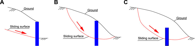
FIGURE 1. Single pile. (A) cantilever pile; (B) wholly buried pile; (C) embedded pile.
The single pile is still widely used, but its limitations are also evident. Because of its structure, the single pile cannot sufficiently resist bending and has a limited rigidity. As a result, the pile’s top and body experience large deformations in the horizontal direction under a landslide thrust (Smethurst and Powrie, 2007), and it is difficult to control these deformations. Therefore, when a single pile is used in a large landslide thrust control project, it must have a large cross section to ensure its ability to control sliding. Two significant problems will follow if the pile’s cross-section area increases.
(i) The consumption of building materials will increase significantly, which results in a higher engineering investment.
(ii) A large section excavation easily induces the risk of landslide failure, which is hard to control.
2.2 Structure development
Compared to other landslide control measures, such as anti-slide retaining walls, drainage ditches, and the roasting method (i.e., a soil improvement technique), the single pile offers prominent advantages. It has a strong anti-slide ability, can be constructed quickly, offers site-setting flexibility, produces few disturbances to the original landslide body, and is highly reliable (Xie et al., 2021). Although technological problems exist in the application of a single pile, it has been widely used because of these prominent advantages (Bellezza and Caferri, 2018). As a result of its widespread use, many types of anti-slide pile structures have been developed.
We studied the anti-slide pile structure development process from a broad perspective and determined that there are two paths of development. In the beginning, the development focused on promoting the applicability of the anti-slide pile, extending its range of application. The typical structures of the combination pile, anchor anti-slide pile, and prestressed-pile were designed following this development path. Over the course of further study focused on pile–soil interactions, the pile–soil coupling effect was considered in the anti-slide pile structure design. At this time, the typical pile–soil coupling structure first appeared, which was designed to make the pile and the soil work together to resist landslide thrust.
2.2.1 Improving the applicability of the anti-slide pile
2.2.1.1 Combination pile
As noted earlier, in a large thrust landslide control project, a single pile structure will perform insufficiently in its bearing capacity and will perform poorly in the technological economy (Shen et al., 2017; Guo et al., 2020). To address these insufficiencies, the combination pile was introduced. The combination pile combines single piles using connecting beams (which can include one, two, or more beams). Because of the different methods of combination, there are many forms of the combination pile. Typical combination piles are the door-frame-type pile, steel-frame-type pile, and h-type pile. Figure 2 shows the three different structures.
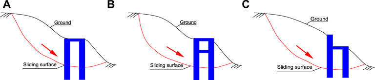
FIGURE 2. Combination pile. (A) door-frame-type pile; (B) steel-frame-type pile; (C) h-type pile.
Compared with the single pile, the combination pile offers two prominent advantages (Dai et al., 2022; Xiong et al., 2022; Zhao et al., 2022).
(i) Combination piles are statically indeterminate structures. Because of the rigid connection of the fore pile, rear pile, and connecting beam, the stiffness of the structure is significant. Moreover, its internal force can be adjusted automatically according to complicated and changeable external forces. Therefore, it can accommodate more complex external forces and is an especially good fit for soft-ground landslides with large residual sliding force.
(ii) The fore pile and rear pile work together to resist positive earth pressure. Their combined action can generate coupled forces that move in the direction opposite to that of the positive earth pressure’s action. These coupled forces are beneficial to the pile body displacement and internal force reduction.
Because of these advantages, until now, these kinds of combination piles have been ideal structures for landslides with large thrust. The cross-section area of combination piles is smaller, and the anchorage depth is shallower than that of other anti-slide pile structures, but the construction process is more complex.
2.2.1.2 Anchor anti-slide pile
Figure 3 shows the anchor anti-slide pile. Unlike traditional single piles, the pile body has been settled using an anchor cable. Settling the anchor cable creates a situation that differs from the traditional situation, in which anti-slide piles bear force passively (Pai and Wu, 2021). As a result, the pile body’s internal force and deformation state are optimized (Xu et al., 2022). This leads to a decrease in the pile body’s cross-section area and anchorage depth (Wu et al., 2015). Following increasing application of the anchor anti-slide pile, disadvantages have also been recognized.
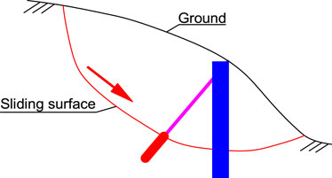
FIGURE 3. Anchor anti-slide pile.
The first disadvantage is the stress relaxation phenomenon of the anchor cable. During the prestress stretching process, cable deformation can result in the loss of prestress. As a result of the cable’s physical properties, this loss of prestress is inevitable during use. Meanwhile, the deformation of the rock and soil mass can also result in the loss of prestress.
The second disadvantage is the rust problem associated with the anchor cable. Under the combined action of water, air, and chemical components that are contained in the rock and soil mass, the prestress anchor cable will rust, which results in a decrease in the designed anchor tension. Even worse, this rust can cause the anchor cable to break.
The third disadvantage is its restricted application. The application of an anchor anti-slide pile, for example, may be restricted by the geological environment (Wang et al., 2022). Although it may be suitable for a rock sliding bed landslide, it is not suitable for a soil sliding bed landslide. For a soil sliding bed landslide, an effective condition may not exist for the anchoring and stretching of a prestress anchor cable.
2.2.1.3 Prestressed-pile
To address the disadvantage of a pile body’s large horizontal displacement, two direct methods can be adopted for a single pile structure. The first increases the cross-sectional area of the pile body, and the second increases the stiffness of the pile body. Based on the second method and as a result of developments in prestress technology, another type of prestressed-pile has appeared. Figure 4 shows a prestressed-pile. The primary improvement made to the prestressed-pile structure is the set of prestress anchor cables attached in the tensile zone of the pile body. By taking advantage of the reverse bending moment that is generated by the vertical prestressed anchor cables to counteract the negative effects of the bending moment induced by the landslide thrust, the pile body deflection can be decreased (Chen and Zhao 2016).
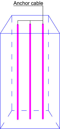
FIGURE 4. Prestressed-pile.
The action mechanism of a prestressed-pile is the same as a normal single pile. The acting force, and the distribution that the landslide body imposes on the pile, do not change noticeably after the prestress anchor cables are installed. The instalment of prestress anchor cables improves the pile’s stress state, and its stiffness is greater than the stiffness of a single pile without prestress anchor cables. Because of this greater stiffness, its horizontal displacement is reduced, and, at the same time, pile body cracks are reduced significantly. Compared with the anchor anti-slide pile, the rust problem associated with anchor cables has also been resolved, as they are enclosed entirely by concrete. Due to its unique advantages, the prestressed-pile is especially suitable for landslide control projects that are located along reservoir banks.
2.2.2 Starting from in-depth study of pile-soil interaction
Throughout the application process of anti-slide piles adopted in landslide control projects, their design theory has achieved significant progress. Previously, the mutual action between the pile and the soil was thought to be separated in the design. The soil was thought to be the load, and the anti-slide pile was thought to be the receptor of that load. Additionally, the connection between the two had not been considered. As a result, the size of the anti-slide pile was designed to be oversized, and the calculated design value of the pile body’s internal force deviated significantly from the field measurement—that is, the safety factor of the landslide control project was oversized as a result of its conservative design. This conservative design also caused significant economic waste. In fact, the pile and the soil were mutually affected during the contact process. The pile deformation was smaller than anticipated because of the soil strength coupling, and the soil pressure changed due to the pile deformation.
Recently, as part of the in-depth study of pile–soil interactions, the above pile–soil coupling effect has also been extensively studied. On the basis of this work, a typical structure of the anti-slide pile became apparent.
2.2.2.1 Surrounding pile–soil anti-slide structure
Zheng et al. (2013) designed the surrounding pile–soil anti-slide structure (Figure 5). This new structure combines a top connecting beam, six surrounding piles, and the soil inside the structure. There are multiple soil arches inside and outside the structure. Because of the presence of these soil arches, the surrounding pile–soil coupling effect results in an integral coupling anti-slide pile. Regarding this integral coupling anti-slide pile, soil is extruded between the back of the surrounding piles and has the tendency to move inside the surrounding piles. Because of the continuous soil movement, the soil inside is compacted and becomes denser. Simultaneously, the inner soil’s shear strength increases. The transmitted soil pressure is greater than the soil shear strength and is transferred to the surrounding piles by the soil arches. The soil arches between the surrounding piles result in a surrounding pile–soil coupling effect, thus enabling the coupling structure to resist the soil pressure behind it.
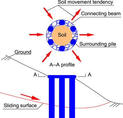
FIGURE 5. Surrounding pile–soil anti-slide structure.
The surrounding pile–soil anti-slide structure is based on this coupling effect; however, before using it widely, several factors need to be resolved, including the efficiency of the pile–soil coupling, the choice of the surrounding pile number, and the plane arrangement of the surrounding piles. According to Zheng et al. (2013), because of the fixed effect of the top connecting beam, the nearby top pile and the coupling effect of the surrounding piles and the soil are good; similarly, due to the anchoring effect of the bottom sliding bed, the nearby slide plane and the coupling effect of the surrounding piles and the soil are good. The coupling effect of the central section between the ground and the slide plane, however, is inadequate. This finding shows that the surrounding pile–soil anti-slide structure is suitable only for shallow- or middle-layer landslides, and, therefore, its application range is limited.
3 A novel anti-slide pile structure
3.1 A new design concept and structure
As presented above, we studied the evolution of anti-slide pile structures and extracted two development paths. Although multiple structural forms have been developed, the two different development paths share a single design concept: The anti-slide pile provides direct resistance to maintain the landslide stability—that is, the anti-slide pile and the landslide body are thought to be confrontational. In addition, based on this design concept, in China, the most popular single pile’s cross section has been deigned up to 3.5 m × 7 m.
Must the landslide body only be viewed as a disaster? Is the landslide body useless? In landslide control with anti-slide piles, the positive role that the landslide body can play should be developed and fully utilized.
Developing and utilizing the landslide body, designing a matched structure of an anti-slide pile that could exert the landslide body’s positive role to a high degree, thus changing the pile–soil confrontational relationship. Following this new line of reasoning, we have designed a novel structure: An arm-stretching-type anti-slide pile. Figure 6 shows the arm-stretching-type anti-slide pile. The unique feature of this new structure is that stretching branches are set on the main pile. The stretching branches can be built in a similar manner to the main pile using the traditional method of manual hole digging and concreting. Or in another way, stretching branches are also able to extend as a result of the impact of high-pressure gas. A high-pressure pump produces this high-pressure gas, which rushes to the inside of the stretching branch through a pressure-resistant tube, and then the stretching branch extends to the designed length. The gas-driven drill may be placed in front of the stretching branch if needed.
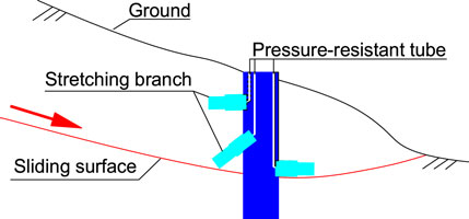
FIGURE 6. Arm-stretching-type anti-slide pile.
The length of the branches can be changed according to the landslide’s actual situation. By adjusting the combined angles of branches and the main pile, the branches change the landslide body’s force distribution and take advantage of the landslide body’s positive role. According to different landslide control demands, the branches can achieve the following:
(i) unload, dividing the landslide body;
(ii) induce back–pressure, converting the slide force to an anti-slide force;
(iii) exert force, changing the passive situation to an active situation; and
(iv) provide support, making use of the landslide body’s reaction force.
When the back branch stretches horizontally, it can divide the landslide body and unload. The landslide body that is on the branch is carried by that branch, such that the soil pressure underneath it is reduced and the overturning moment is reduced accordingly. At the same time, the landslide body that is on the branch will generate a reverse moment that counteracts the moment generated by the landslide body. When the stretch of the back branch is inclined downward, it induces back-pressure. In this situation, the inclined branch acts like an artificial sliding surface by inducing the landslide body that is on the branch to slide and pressing back on the sliding body. When the back branch stretches upward, it can exert force on the sliding body underneath it due to the compression result of the landslide body sliding and the main pile stopping. This active force on the sliding body increases the friction force, and, as a result, landslide stability will increase accordingly. When the front branch stretches horizontally, inclined downward or upward, it provides supporting force. In these situations, the branch utilizes the reaction force of the soil underneath it. Thus, a disadvantage like the single pile’s insufficient bending resistance is improved. The branch could also be set on both sides of the main pile, and, in this situation, it will enlarge the scope of influence of the pile, thus enlarging pile spacing. All of the installed branches could be simultaneously optimized with respect to stretching length and angle to develop and utilize the landslide body’s positive role to the uppermost and improve the pile’s stress state at the same time.
3.2 Simulation verification
To verify the new concept and structure, we first choose the method of simulation (Han et al., 2019). A typical three-dimensional model of a landslide controlled by an anti-slide pile was established using ABAQUS (Tang et al., 2018). The wholly buried pile and the arm-stretching-type anti-slide pile with two horizontal branches were selected to compare with respect to landslide control.
The simulation parameters are shown in Table 1; Figure 7. Figure 7A shows the geometrical parameters of the landslide and the pile. In Figure 7B, the shaded half-pile model was analyzed in the numerical simulation on the basis of symmetry (Li et al., 2015). The soil followed the Mohr–Coulomb criterion during the analysis, and the pile was isotropic elastic. Both the soil and the pile used the C3D8 unit for modelling. The pile-soil interaction was applied as a surface-to-surface contact type. The model bottom was constrained as fixed, while normal constraints were applied to the front, rear, left side, and right side of the model.
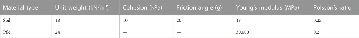
TABLE 1. Main parameters of the simulation.
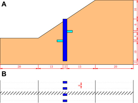
FIGURE 7. Model geometric parameters. (A) longitudinal section and (B) horizontal section.
The landslide features a homogeneous soil slope. Based on the strength reduction method, its safety factor is 0.965 when the calculation is terminated. Figure 8 shows a cloud map of the plastic strain. The direct value showing the effect of the novel structure is the safety factor. Figure 9 shows the relationship between the safety factor and the horizontal displacement at the slope toe node. It is evident that, whether adopting the nonconvergence of calculation or the inflection point of displacement as the safety factor evaluation criterion, the safety factor of the arm-stretching-type anti-slide pile controlled landslide is obviously bigger than that of the wholly buried pile. In addition, as the calculation is terminated, the safety factor of the controlled project increased to 1.196 and 1.717 following the conventional wholly buried pile treatment and the arm-stretching-type anti-slide pile treatment, respectively. Compared to the common wholly buried pile, the novel structure–controlled project’s safety factor improves by 43.56%.
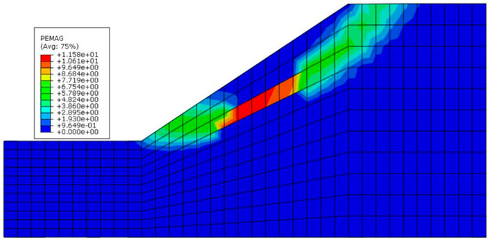
FIGURE 8. Plastic strain cloud map.
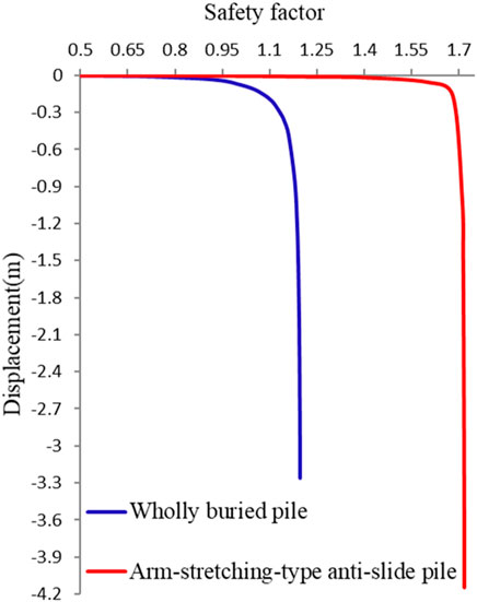
FIGURE 9. Relationship between the safety factor and the displacement of slope toe node.
Figure 10 shows the displacement cloud map when the calculation is terminated. Comparing the two figures, it can be seen that the sliding surfaces are obviously different, which fully indicates that the setting of branches can change the distribution of the landslide force system, and therefore the landslide body’s positive role can be developed and utilized if the branches are set properly. Figure 11 shows that after the two branch settings, the main pile body stress can be reduced and adjusted more uniformly, and this will result in the pile strength being fully utilized. The great improvement is likely the result of the synergistic action of the back branch’s unloading effect and the front branch’s supporting effect.
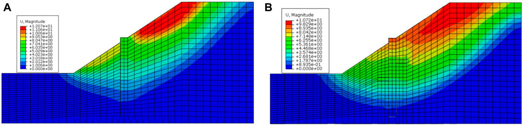
FIGURE 10. Displacement cloud map. (A) wholly buried pile and (B) arm-stretching-type anti-slide pile.
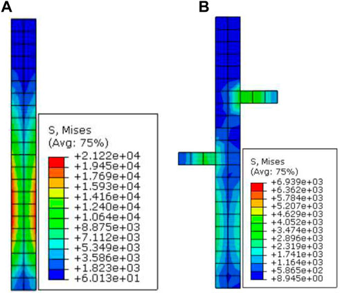
FIGURE 11. Stress distribution. (A) wholly buried pile and (B) arm-stretching-type anti-slide pile.
4 Discussion
According to the anti-slide pile structures’ evolution law, we identified two development paths. The first path was aimed at improving the applicability of anti-slide piles, and the second path started from an in-depth study of pile–soil interactions. Following these two development paths, many different types of anti-slide pile structures have been designed. The combination pile is suitable for large thrust landslides, the anchor anti-slide pile is suitable for rock sliding bed landslides, and the prestressed-pile is suitable for reservoir bank landslides. These three typical anti-slide piles are suitable for different landslide environments. With continued research into pile–soil interactions, a new type of surrounding pile–soil anti-slide pile structure emerged, the design of which is based on the coupling effect. The coupling effect between the surrounding piles and the soil inside allows them to couple as an entity that is to provide sufficient resistance to maintain landslide stability. The surrounding pile–soil anti-slide structure is suitable for shallow- or middle-layer landslides.
The anti-slide pile structure has followed different development paths and has taken multiple forms, but these forms share a single design concept: The anti-slide pile provides direct resistance to maintain landslide stability, that is, the anti-slide pile and the landslide body are considered to be confrontational sides. In the design of the surrounding pile–soil anti-slide structure, the soil inside the surrounding piles was used; however, the surrounding pile–soil coupling structure was viewed as an entity that was also able to provide sufficient resistance to maintain landslide stability. The use of the soil inside the surrounding piles was supportive but limited. Until now, in landslide control projects that adopt anti-slide piles, the landslide body has been viewed only as a hazard. The positive effects of the landslide body have not been considered previously.
While shifting away from the view that the landslide body is only a hazard in landslide control with anti-slide piles, its positive role should be developed and utilized. Following this concept, the traditional design concept of the anti-slide pile should be improved by developing a new type of anti-slide pile structure that can exert the positive role of the landslide body. We have undoubtedly provided support for this new concept of anti-slide pile design—that is, the arm-stretching-type anti-slide pile. According to the simulation results, the arm-stretching-type anti-slide pile could achieve the aim of developing and utilizing the landslide body. At the same time, the stress distribution of the pile will be adjusted more reasonably, resulting in an increase in pile stability and carrying capacity, thus reducing pile anchorage depth and cross-section size. Ultimately, investment costs will decrease, and pile efficiency will increase.
5 Conclusion and prospects
For a long time, the anti-slide pile has been applied widely in landslide control projects. By relying on the anti-slide pile’s strength to resist the landslide thrust, the aim is to maintain landslide stability. Until now, all anti-slide piles have been designed to provide direct resistance to maintain the landslide stability; that is, the pile and the landslide body have been thought to be confrontational sides, and so the positive role of the landslide body had not been considered in pile structure design. Although the surrounding pile–soil anti-slide structure uses the soil inside the surrounding piles, its design still falls under the concept of pile–soil confrontation, and its use remains limited.
The arm-stretching-type anti-slide pile offers a new concept for anti-slide pile design. Following this new line of thinking, the landslide body’s positive role can be developed and utilized. This study develops the anti-slide pile design concept, moving it from the existing slide–resist single mode to the slide–self-stabilize–resist compound mode. The novel structure offers great theoretical significance and high engineering application value. Considering the construction process, this new type of pile is expected to be particularly suitable for treating filled slopes.
The prominent advantage of the arm-stretching-type anti-slide pile lies in the proper setting of stretching branches. How to set the branches according to different landslide types must be further studied. The novel structure’s force calculation model must also be developed accordingly.
Data availability statement
The raw data supporting the conclusion of this article will be made available by the authors, without undue reservation.
Author contributions
Conceptualization, GC; supervision, GZ; software, GC, FG, JL, and LD; writing—original draft, GC and FG; writing—review and editing, FG. All authors reviewed the manuscript.
Funding
This work was supported by the Open Research Fund of the State Key Laboratory of Geomechanics and Geotechnical Engineering, Institute of Rock and Soil Mechanics, Chinese Academy of Sciences, Grant No. SKLGME021015, the Teaching Research Project of China Three Gorges University, Grant No. J2022043, the Teaching Research Project, College of Civil Engineering and Architecture, China Three Gorges University, Grant No. TJJ202103, and the 111 Project of Hubei Province, Grant No. 2021EJD026.
Conflict of interest
The authors declare that the research was conducted in the absence of any commercial or financial relationships that could be construed as a potential conflict of interest.
Publisher’s note
All claims expressed in this article are solely those of the authors and do not necessarily represent those of their affiliated organizations, or those of the publisher, the editors and the reviewers. Any product that may be evaluated in this article, or claim that may be made by its manufacturer, is not guaranteed or endorsed by the publisher.
References
Al-Defae, A. H., and Knappett, J. A. (2015). Newmark sliding block model for pile-reinforced slopes under earthquake loading. Soil Dyn. Earthq. Eng. 75, 265–278. doi:10.1016/j.soildyn.2015.04.013
Ausilio, E., Conte, E., and Dente, G. (2001). Stability analysis of slopes reinforced with piles. Comput. Geotech. 28, 591–611. doi:10.1016/S0266-352X(01)00013-1
Bellezza, I., and Caferri, L. (2018). Ultimate lateral resistance of passive piles in non-cohesive soils. Geotech. Lett. 8, 5–12. doi:10.1680/jgele.17.00113
Chen, G. F., Zou, L. C., Wang, Q., and Zhang, G. D. (2020). Pile-spacing calculation of anti-slide pile based on soil arching effect. Adv. Civ. Eng. 2020, 1–6. doi:10.1155/2020/7149379
Chen, H. K., and Zhao, C. H. (2016). Study on the optimum design method for vertical pre-stressed anchor anti-slide piles with trapezoid section. J. ChongQing Jiaot. Univ. Nat. Sci.) 35, 54–59. doi:10.3969/j.issn.1674-0696.2016.02.13
Chen, Z., Song, D. P., and Dong, L. H. (2021a). Characteristics and emergency mitigation of the 2018 laochang landslide in tianquan county, sichuan Province, China. Sci. Rep. 11, 1578. doi:10.1038/s41598-021-81337-x
Chen, Z., Shuai, F. X., Cao, C. X., Xu, H. L., Shang, Y. Q., and Sun, H. Y. (2021b). A new method to prevent seepage erosion of loess slope toe using the combination of filter pipe and siphon drainage. Bull. Eng. Geol. Environ. 80, 4171–4190. doi:10.1007/s10064-021-02182-w
Chow, Y. K. (1996). Analysis of piles used for slope stabilization. Int. J. Numer. Anal. Methods Geomech. 20, 635–646. doi:10.1002/(sici)1096-9853(199609)20:9<635::aid-nag839>3.0.co;2-x
Dai, Z. H., Qiu, Z. H., Li, H. Y., Lu, C. J., and Yang, J. H. (2022). Laboratory model test of fully buried portal frame-shaped slope-stabilizing piles. Geotech. Test. J. 45, 20210031–20210410. doi:10.1520/GTJ20210031
Fang, K., Tang, H. M., Li, C. D., Su, X. X., An, P. J., and Sun, S. X. (2023). Centrifuge modelling of landslides and landslide hazard mitigation: A review. Geosci. Front. 14, 101493. doi:10.1016/j.gsf.2022.101493
Godt, J. W., Baum, R. L., and Lu, N. (2009). Landsliding in partially saturated materials. Geophys. Res. Lett. 36. doi:10.1029/2008GL035996
Guo, Z. Z., Chen, L. X., Yin, K. L., Shrestha, D. P., and Zhang, L. (2020). Quantitative risk assessment of slow-moving landslides from the viewpoint of decision-making: A case study of the three Gorges reservoir in China. Eng. Geol. 273, 105667. doi:10.1016/j.enggeo.2020.105667
Guo, Z. Z., Shi, Y., Huang, F. M., Fan, X. M., and Huang, J. S. (2021). Landslide susceptibility zonation method based on C5.0 decision tree and K-means cluster algorithms to improve the efficiency of risk management. Geosci. Front. 12, 101249. doi:10.1016/j.gsf.2021.101249
Han, Z., Su, B., Li, Y. G., Ma, Y. F., Wang, W. D., and Chen, G. Q. (2019). Comprehensive analysis of landslide stability and related countermeasures: A case study of the lanmuxi landslide in China. Sci. Rep. 9, 12407. doi:10.1038/s41598-019-48934-3
Hassiotis, S., Chameau, J. L., and Gunaratne, M. (1997). Design method for stabilization of slopes with piles. J. Geotech. Geoenviron. Eng. 123, 314–323. doi:10.1061/(asce)1090-0241(1997)123:4(314)
Huang, Y., Xu, X., Liu, J. J., and Mao, W. W. (2020). Centrifuge modeling of seismic response and failure mode of a slope reinforced by a pile-anchor structure. Soil Dyn. Earthq. Eng. 131, 106037. doi:10.1016/j.soildyn.2020.106037
Lei, H. Y., Liu, X., Song, Y. J., and Xu, Y. G. (2021). Stability analysis of slope reinforced by double-row stabilizing piles with different locations. Nat. Hazards 106, 19–42. doi:10.1007/s11069-020-04446-2
Li, X. P., Pei, X. J., Gutierrez, M., and He, S. M. (2012). Optimal location of piles in slope stabilization by limit analysis. Acta Geotech. 7, 253–259. doi:10.1007/s11440-012-0170-y
Li, C. D., Wu, J. J., Tang, H. M., Wang, J., Chen, F., and Liang, D. M. (2015). A novel optimal plane arrangement of stabilizing piles based on soil arching effect and stability limit for 3D colluvial landslides. Eng. Geol. 195, 236–247. doi:10.1016/j.enggeo.2015.06.018
Liang, R. Y., Joorabchi, A. E., and Li, L. (2014). Analysis and design method for slope stabilization using a row of drilled shafts. J. Geotech. Geoenviron. Eng. 140. doi:10.1061/(ASCE)GT.1943-5606.0001070
Liu, X. R., Kou, M. M., Feng, H., and Zhou, Y. (2018). Experimental and numerical studies on the deformation response and retaining mechanism of h-type anti-sliding piles in clay landslide. Environ. Earth Sci. 77, 163. doi:10.1007/s12665-018-7360-3
Liu, X. L., Yan, J. K., Tong, B., and Liu, L. (2021). Evaluation of micropiles with different configuration settings for landslide stabilization based on large scale experimental testing. Front. Earth Sci. 9, 693639. doi:10.3389/feart.2021.693639
Medina, V., Hurlimann, M., Guo, Z. Z., Lloret, A., and Vaunat, J. (2021). Fast physically-based model for rainfall-induced landslide susceptibility assessment at regional scale. Catena 201, 105213. doi:10.1016/j.catena.2021.105213
Pai, L. F., and Wu, H. G. (2021). Shaking table test of comparison and optimization of seismic performance of slope reinforcement with multi-anchor piles. Soil Dyn. Earthq. Eng. 145, 106737. doi:10.1016/j.soildyn.2021.106737
Shen, Y. J., Yu, Y., Ma, F., Mi, F. L., and Xiang, Z. L. (2017). Earth pressure evolution of the double-row long-short stabilizing pile system. Environ. Earth Sci. 76, 586. doi:10.1007/s12665-017-6907-z
Smethurst, J. A., and Powrie, W. (2007). Monitoring and analysis of the bending behaviour of discrete piles used to stabilise a railway embankment. Geotechnique 57, 663–677. doi:10.1680/geot.2007.57.8.663
Song, Y. S., Hong, W. P., and Woo, K. S. (2012). Behavior and analysis of stabilizing piles installed in a cut slope during heavy rainfall. Eng. Geol. 129-130, 56–67. doi:10.1016/j.enggeo.2012.01.012
Tang, L., Cong, S. Y., Xing, W. Q., Ling, X. Z., Geng, L., Nie, Z., et al. (2018). Finite element analysis of lateral Earth pressure on sheet pile walls. Eng. Geol. 244, 146–158. doi:10.1016/j.enggeo.2018.07.030
Wang, L. P., and Zhang, G. (2014). Centrifuge model test study on pile reinforcement behavior of cohesive soil slopes under earthquake conditions. Landslides 11, 213–223. doi:10.1007/s10346-013-0388-2
Wang, Y., Zheng, T., Sun, R., Qi, W. H., and Qi, W. W. (2022). Influence of slope amplification on the pile dynamic behavior based on the data mining method. Front. Earth Sci. 10, 885586. doi:10.3389/feart.2022.885586
Wu, R. Z., Zhou, H. Q., Hu, Y., Zhong, Y. Y., Li, P. J., and Yang, J. H. (2015). An improved method for calculating anti-sliding pile with prestressed anchor cable based on finite difference theory. Rock Soil Mech. 36, 1791–1800. doi:10.16285/j.rsm.2015.06.034
Xiao, S. G. (2017). A simplified approach for stability analysis of slopes reinforced with one row of embedded stabilizing piles. Bull. Eng. Geol. Environ. 76, 1371–1382. doi:10.1007/s10064-016-0934-y
Xiao, S. G., Zeng, J. X., and Yan, Y. P. (2017). A rational layout of double-row stabilizing piles for large-scale landslide control. Bull. Eng. Geol. Environ. 76, 309–321. doi:10.1007/s10064-016-0852-z
Xie, Q., Cao, Z. L., Shi, X. K., Fu, X., Ban, Y. X., and Wu, Z. H. (2021). Model test of interaction between load-caused landslide and double-row anti-slide piles by transparent soil material. Arab. J. Sci. Eng. 46, 4841–4856. doi:10.1007/s13369-020-05256-1
Xiong, S., Li, C. D., Yao, W. M., Yan, S. Y., Wang, G. H., and Zhang, Y. Q. (2022). Physical model tests and numerical modeling of stabilizing mechanism of portal double-row piles in landslides with interbedded weak and hard bedrock. Bull. Eng. Geol. Environ. 81, 101. doi:10.1007/s10064-022-02607-0
Xu, X., Huang, Y., Yashima, A., and Du, X. L. (2022). Failure evolution process of pile-anchor reinforced rock slope based on centrifuge shaking table tests. Eng. Geol. 311, 106920. doi:10.1016/j.enggeo.2022.106920
Zhang, G., and Wang, L. P. (2016). Integrated analysis of a coupled mechanism for the failure processes of pile-reinforced slopes. Acta Geotech. 11, 941–952. doi:10.1007/s11440-015-0410-z
Zhang, G., Wang, L. P., and Wang, Y. L. (2017). Pile reinforcement mechanism of soil slopes. Acta Geotech. 12, 1035–1046. doi:10.1007/s11440-017-0543-3
Zhang, Y. M., Hu, X. L., Tannant, D. D., Zhang, G. C., and Tan, F. L. (2018). Field monitoring and deformation characteristics of a landslide with piles in the Three Gorges Reservoir area. Landslides 15, 581–592. doi:10.1007/s10346-018-0945-9
Zhao, B., Wang, Y. S., Wang, Y., Shen, T., and Zhai, Y. C. (2017). Retaining mechanism and structural characteristics of h type anti-slide pile (hTP pile) and experience with its engineering application. Eng. Geol. 222, 29–37. doi:10.1016/j.enggeo.2017.03.018
Zhao, G. Q., Yang, Y. Y., Zhang, H. Q., and Zhang, G. L. (2019). A case study integrating field measurements and numerical analysis of high-fill slope stabilized with cast-in-place piles in Yunnan, China. Eng. Geol. 253, 160–170. doi:10.1016/j.enggeo.2019.03.005
Zhao, L. H., Liao, W. F., Li, L., and Hu, S. H. (2022). Improved calculation method for the internal force of h-type prestressed anchor cable antislide piles. Int. J. Geomech. 22, 04022187. doi:10.1061/(ASCE)GM.1943-5622.0002525
Keywords: anti-slide pile, development path, design concept, landslide body development and utilization, arm-stretching-type anti-slide pile
Citation: Chen G, Guo F, Zhang G, Liu J and Ding L (2023) Anti-slide pile structure development: New design concept and novel structure. Front. Earth Sci. 11:1133127. doi: 10.3389/feart.2023.1133127
Received: 28 December 2022; Accepted: 18 January 2023;
Published: 26 January 2023.
Edited by:
Zizheng Guo, Hebei University of Technology, ChinaCopyright © 2023 Chen, Guo, Zhang, Liu and Ding. This is an open-access article distributed under the terms of the Creative Commons Attribution License (CC BY). The use, distribution or reproduction in other forums is permitted, provided the original author(s) and the copyright owner(s) are credited and that the original publication in this journal is cited, in accordance with accepted academic practice. No use, distribution or reproduction is permitted which does not comply with these terms.
*Correspondence: Fei Guo, eWJibnVpLjIwMDhAMTYzLmNvbQ==; Guodong Zhang, emdkQGN0Z3UuZWR1LmNu