 Quan Li
 Qiang Ma
- Science and Technology on Reactor System Design Technology Laboratory, Nuclear Power Institute of China, Chengdu, China
In nuclear reactors, the research of conjugated heat transfer between the fuel and coolant in the fuel assembly is fundamental for improving the safety, reliability and economy. The numerical approach based on Computational Fluid Dynamics (CFD) can be used to realize the rapid analysis of the conjugated heat transfer. Besides, the numerical simulation can provide detailed physical fields that are useful for the designing and optimizing of the fuel assembly. The plate-type fuels are generally used to enhance heat transfer in research reactors with high power density. In this study, a standard plate-type fuel assembly in the research reactor was taken into consideration. The solid-fluid conjugated heat transfer of the fuel assembly and coolant was numerically investigated. In the fluid region, the subcooled flow boiling simulation model was established by implementing the Rensselaer Polytechnic Institute model into the Euler multi-phase flow method. The results show that the conjugated heat transfer of the fuel assembly and coolant can be simulated using the model established in this work. The influence of fluid velocity, power density and the width of the flow channel on the temperature distribution and the conjugated heat transfer was investigated and discussed.
Introduction
Research reactors are widely used to produce high neutron flux for research, training, education, and irradiation test (Gong et al., 2015; Guo et al., 2018). The fuel assembly used in the research reactors is generally the plate-type fuel assembly, including several fuel plates, two side plates and narrow rectangular channels formed between the fuel plates. The research of heat transfer of the fuel assembly is fundamental for improving the safety, reliability and economy. However, the coolant flow and heat transfer characteristics in the narrow rectangular channels are significantly different from those of conventional channels and tubes (Sun et al., 2020). Therefore, investigation of coolant flow and heat transfer characteristics in the plate-type fuel assembly is important for research reactors designing.
In the last few years, 1-dimensional codes, 1.5-dimensional codes and 2-dimensional codes, such as the RELAP5/MOD3 (Lu et al., 2009; Son et al., 2015), FRAPCON (Phillippe et al., 2012), FEMAX (Yoo et al., 2006) and FROBA (Deng et al., 2016) were used for the thermo-mechanical coupling analysis and safety analyses of the fuels. In order to improve the accuracy of the calculation, 3-dimensional simulations based on MOOSE (He et al., 2018) and COMSOL (Liu and Zhou, 2017) were used. However, the fluid was considered as 1-dimensional flow in the calculations and the detailed flow and heat transfer characteristics cannot be obtained.
The numerical investigation based on Computational Fluid Dynamics (CFD) can provide 3-dimensional detailed physical fields that are useful for the designing and optimizing of the fuel assembly. Recently, with the help of CFD, some researchers investigated the thermal-hydraulic characteristics of the fuel assembly. Li et al. (2020) numerically investigated the flow fields and phase distributions in the subchannel of a pressurized water reactor fuel assembly based on the CFD model of subcooled flow boiling. Kumar et al. (2018) and Zhang and Liu (2020) carried out CFD simulations to predict the void and temperature distribution inside the rod bundle. The influence of the spacer grid on the flow and heat transfer characteristics of subcooled flow boiling was studied by Zhang and Liu (2020). Shirvan (2016) numerically investigated the boiling crisis for helical cruciform-shaped rods using commercial software Star CCM+.
As for the plate-type fuel assembly, some researchers focused on the single-phase flow in the channels (Gong et al., 2015; González Mantecón and Mattar Neto, 2018; Liao et al., 2020). Gong et al. (2015) investigated the heat transfer characteristics of the plate-type fuel assembly. The single-phase turbulence flow was calculated using the commercial software FLUENT. The temperature distribution of the fuel assembly was obtained with different coolant inlet velocity and the assembly with a hot spot was specially studied. Liao et al. (2020) conducted the fluid-solid coupling simulation with the consideration of irradiation effects for plate-type fuel assembly. The thermo-hydraulic model in the fluid domain was established based on FLUENT. González Mantecón and Mattar Neto (2018) numerically investigated fluid-structure interaction of the plate-type fuel assemblies using the commercial software ANSYS CFX for modeling fluid flow and ANSYS Mechanical for modeling the plates. The maximum deflection of the plates was detected at the leading edge. An extra deflection peak was observed near the trailing edge of the plates for fluid velocities greater than the Miller’s velocity.
The research of subcooled flow boiling heat transfer in the fuel assembly is fundamental for improving the safety, reliability and economy. However, fewer thermal-hydraulic investigations of the plate-type fuel assembly have taken the subcooled flow boiling into consideration. Guo et al. (2018) conducted the thermal-hydraulic analysis of flow blockage in the fuel assembly in the JRR-3M research reactor. The 3-dimensional model of the fuel assembly was built and the flow and heat transfer characteristics were simulated using FLUENT. Guo et al. (2018) found when the blockage ratio of the fuel assembly is 70%, the departure from nucleate boiling will occur. Park et al. (2021) investigated the thermal-hydraulic behaviors of flow channels of the plate-type fuel assembly by the CFD simulation with a multi-phase flow model. The wall boiling model proposed by Kurul and Podowski (1991) was used and the influence of the flow channel blockage on the flow instability and heat transfer was studied.
In this work, a standard plate-type fuel assembly in a research reactor was taken into consideration. The solid-fluid conjugated heat transfer of the fuel assembly and the coolant was numerically investigated. In the simulation, the Euler multi-phase flow method was used with the Rensselaer Polytechnic Institute (RPI) wall boiling model implemented. The temperature distribution and the flow field of the fuel assembly were obtained. The influence of power density, fluid inlet velocity and subchannel width on the conjugated heat transfer was investigated.
Mathematic Model and Numerical Method
The simulation of conjugated heat transfer considering the phase change process is complicated. In this work, the conjugated heat transfer model was established. The simulation domain was divided into the solid region and the fluid region. The heat transfer of each region was calculated using different models and the heat transfer between the two regions was calculated.
Solid Region
In the solid region, heat is transferred by conduction. Since the thermal conductivity of the solid was assumed as constant, the heat transfer of the solid region was calculated by
where
Fluid Region
In the fluid region, the subcooled flow boiling was numerically simulated based on the Euler multi-phase flow method with liquid water being the primary phase and water vapor being the second phase. The volume fraction was used to represent the content of each phase and only two phases were set in the fluid region.
where
The governing equations included the mass conservation equations, the momentum conservation equations and the energy conservation equations for each phase. In order to simplified the description of the governing equations, the subscripts p and q were used denote the two phases.
1) Mass conservation equations
The mass conservation equation for phase q in the Euler multi-phase flow method was
where ρq and uq are the density and the velocity of phase q respectively,
2) Momentum conservation equations
The momentum conservation equation for phase q in the Euler multi-phase flow method was
where
where
The standard k-ε turbulence model was chosen to calculate the effect of turbulent flow and the two-layer model with all y+ wall function was employed. Generally, the interfacial momentum transfer between liquid and vapor should be the sum of the drag force, turbulent dispersion force, lift force, wall lubrication force and virtual mass force.
The sensitivity analysis of the forces on the simulation result of subcooled flow boiling was conducted. The simulation object and conditions were the same as those in the experiment conducted by Zeitoun and Shoukri (1996). The channel geometry was an annulus with a 306 mm length. The outer wall diameter was 25.4 mm and the heated inner wall diameter was 12.7 mm. The heat flux of the inner wall of the channel was 508 kW/m2, the mass flux of the coolant was 264.3 kg/(m2 s), the coolant inlet temperature was 94.6°C and the system pressure was 150 kPa. The result shows that the influence of the lift force, wall lubrication force and virtual mass force on the calculated wall temperature was less than 1 K. Similar to the results of the sensitivity analysis we finished in our previous work (Li et al., 2018), the effects of the three forces are to move the vapor bubbles radially away from or towards the heated surface. While the forces have little influence on the void fraction distribution along the coolant flow direction.
Since the lift force, wall lubrication force and virtual mass force have little effect on the simulation results and the inclusion of the three forces takes more time to obtain convergence, only the drag force and turbulent dispersion force were taken into consideration in this work.
where FD,k is the drag force and FTD,k is the turbulent dispersion force.The drag force can by calculated using
where ur = ul-uv is the relative velocity between the two phases, dB is the bubble diameter and CD is the drag force coefficient. In this work, the bubble diameter was calculated using the Anglart’s method (Anglart and Nylund, 1996) and the drag force coefficient was calculated using the Tomiyama’s method (Tomiyama, 2004).
The turbulent dispersion force plays an important role in taking the vapor bubbles from the near wall region to the bulk liquid region. The turbulent dispersion force was calculated using the method proposed by Lopez de Bertodano (1991).
where CTD is the turbulent dispersion coefficient and kl is the turbulent kinetic energy of the liquid phase.
3) Energy conservation equations
The energy conservation equation for phase q in the Euler multi-phase flow method was
where hq is the specific enthalpy of phase q, qq is the heat flux, hqp and hpq are the interphase enthalpy.
Solid-Fluid Boundary
At the solid-fluid boundary, heat transferred from the solid region to the fluid region.
where
Wall Boiling Model
Figure 1 shows the schematic of wall boiling heat flux partitioning. The Rensselaer Polytechnic Institute (RPI) wall boiling model (Kurul and Podowski, 1991) divided the total heat flux from the hot wall to the fluid region
where
where
where
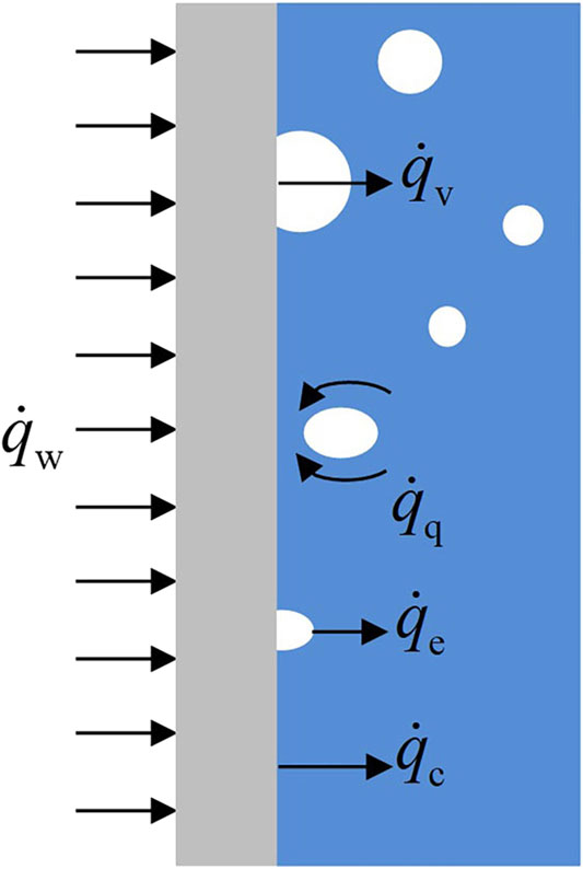
FIGURE 1. Schematic of wall boiling heat flux partitioning.
In this work, the widely used active nucleation site density model proposed by Lemmert and Chawla (1977), the bubble departure diameter model proposed by Tolubinsky and Kostanchuk (1970) and the bubble departure frequency model proposed by Cole (1960) were used. In Tolubinsky’s model, D0 was 0.6 mm.
Model Validation
Due to the lack of experimental results of subcooled flow boiling in the plate-type fuel assembly, the conjugated heat transfer model was validated using the experimental results of subcooled flow boiling in a tube conducted by Bartolemei and Chanturiya (1967) and the experimental results of subcooled flow boiling in an annulus channel conducted by Zeitoun and Shoukri (1996). In Bartolemei’s work, the tube diameter was 15.4 mm, the heat flux of the tube wall was 0.57 MW/m2, the mass flux of the coolant was 900 kg/(m2 s), the subcooled temperature of the coolant was 60 K and the system pressure was 4.5 MPa. The coolant temperature, wall temperature and void fraction were measured by Bartolemei and Chanturiya (1967). Since the system pressure in Bartolemei’s work was larger than that in our simulation for plate-type fuel assembly, the experimental results at lower system pressure obtained by Zeitoun and Shoukri (1996) were also used to validate the model. Figures 2A,B show the comparison of the numerical results of the coolant temperature, wall temperature and void fraction along the coolant flow direction with the experimental results obtained by Bartolemei and Chanturiya (1967). Figure 2C shows the comparison of the numerical results of void fraction along the coolant flow direction with the experimental results obtained by Zeitoun and Shoukri (1996). It can be seen that the calculated results agree well with the measured data and the calculated void fraction is slightly larger than the measured data at lower system pressure.
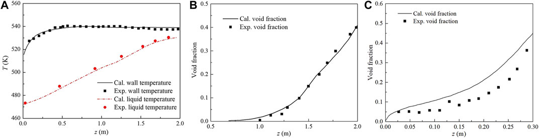
FIGURE 2. Model validation of axial distribution of (A) wall temperature, coolant temperture and (B) void fraction in tube and (C) void fraction in annulus channel.
Physical Model
In this work, a standard plate-type fuel assembly of the research reactor was chosen as the simulation object. The structure, material and thermal-hydraulic parameters of the fuel assembly were the same as those used in Gong’s work (Gong et al., 2015). Table 1 shows the structure, material and thermal-hydraulic parameters of the standard plate-type fuel assembly.
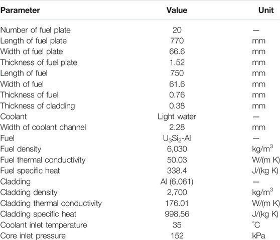
TABLE 1. Parameters of the research reactor fuel assembly.
A three-dimensional model of the standard plate-type fuel assembly was built on the Star CCM+ platform. Figure 3 shows the simulation domain of the conjugated heat transfer of the plate-type fuel assembly. The simulation domain included the inlet section, the test section and the outlet section. In the test section, there were 20 fuel plates with 1.52 mm thickness and 19 subchannels with 2.28 mm width and two by-pass subchannels with 1.24 mm width. The fuel, cladding and coolant parts were considered in the simulation domain. As shown in Figure 3B, half of the fuel assembly was included in the simulation domain due to the symmetry of the geometry and the fluid field.
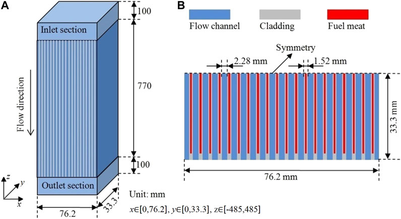
FIGURE 3. Schematic of (A) simulation domain and (B) Cross section.
The hexahedral mesh was used for the physical model. In the mesh independence analysis, a single calculation unit of the assembly was used. A flow channel with two half of the fuel plates was included in the unit. The power distribution of the fuel was assumed to be uniform with 2.35 × 10⁹ W/m3. The coolant inlet temperature, inlet velocity and the system pressure were 35°C, 4.5 m/s and 152 kPa, respectively. Figure 4 shows the calculation results of coolant outlet temperature and the coolant temperature at the center of the calculation region with different number of grid cells. The calculation results of the coolant outlet temperature change a little with the number of grid cells due to the energy conservation. The coolant temperature at the center of the calculation region changes a little when the number of grid cells exceeds 180,000. Thus, the mesh with a 189,000 grid cells was used in this work and the same meshing method was used for the whole fuel assembly. The cell size was chosen as Δx ≈ 0.23 mm, Δy ≈ 1.1 mm, Δz ≈ 2 mm in the fluid domain and Δx ≈ 0.19 mm, Δy ≈ 2.4 mm, Δz ≈ 3 mm in the solid domain.
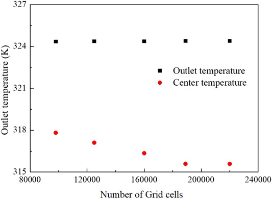
FIGURE 4. Calculation results of cases with different number of grid cells.
Results and Discussion
Conjugated Heat Transfer of the Assembly
The conjugated heat transfer of the plate-type fuel assembly was carried out. The power distribution of each plate along height direction was assumed to be a cosine distribution as
where qmax is the maximum power density and was set as 3.654 × 10⁹ W/m3, H is the height of the fuel.
Figure 5 shows the temperature distribution of the fuel plates and Figure 6 shows the temperature distribution of the coolant. The maximum temperature appears near the center of the fuel plate due to the non-uniform power density distribution of the fuel. Since the power density is zero, the temperature near the ends of the fuel plate equals to the coolant temperature approximately.
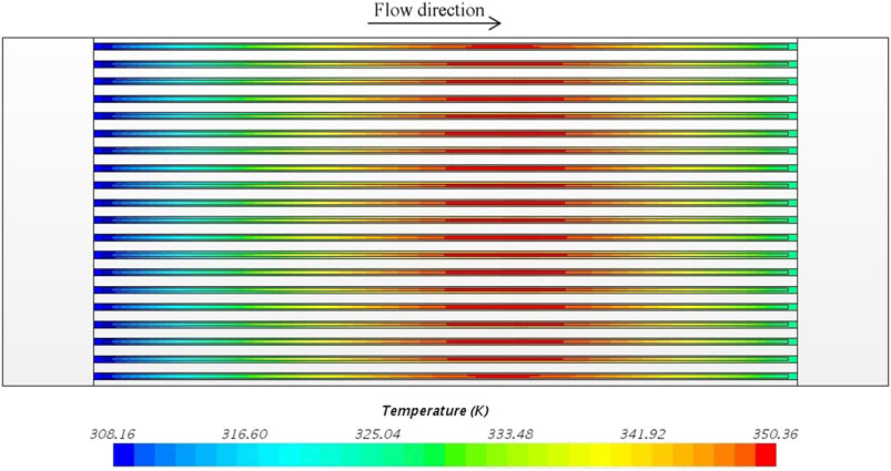
FIGURE 5. Temperature distribution of the fuel plates (scale: x:z = 1:5).
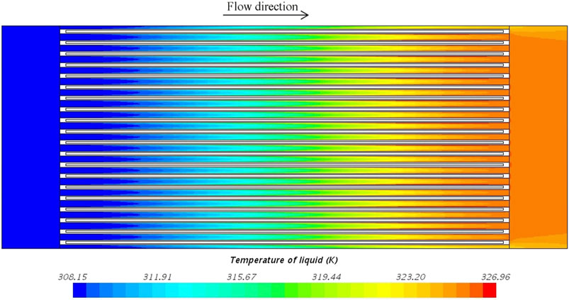
FIGURE 6. Temperature distribution of the coolant (scale: x:z = 1:5).
Conjugated Heat Transfer of a Single Unit
In order to reduce the time consuming of the simulation, the conjugated heat transfer of a single unit was investigated in this section. The influence of power density, inlet velocity and channel width on the conjugated heat transfer was investigated.
Influence of Inlet Velocity
Figure 7 shows the coolant outlet temperature, maximum coolant temperature, maximum cladding temperature and maximum fuel temperature with different inlet velocities. The uniform power density of the fuel was 2.35 × 10⁹ W/m3 and the coolant inlet temperature was 35°C. As shown in Figure 7, the temperatures of the coolant, cladding and fuel decrease with the increase of the inlet velocity due to the increase of the coolant mass flux. Within the inlet velocity range of 1.5–7.5 m/s, the maximum coolant temperature was lower than the saturation temperature of the coolant. The fuel plate can keep safe since no local nucleate boiling occurs. The difference between the coolant temperature and the cladding temperature is the smallest with 7.5 m/s inlet velocity due to the enhancement of single phase convective heat transfer at the highest inlet velocity.
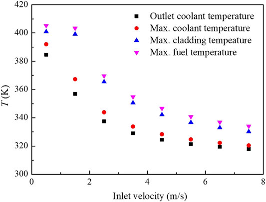
FIGURE 7. Temperatures of coolant, cladding and fuel with different inlet velocities.
With 0.5 m/s inlet velocity, the maximum coolant temperature exceeds the saturation temperature of the coolant, which means the boiling phase change occurs in the flow channel. As shown in Figure 7, the difference between the coolant temperature and the cladding temperature is small with 0.5 m/s inlet velocity. This is because the nucleate boiling occurs and the heat transfer between the coolant and the cladding was enhanced by nucleate boiling. Figure 8 shows the void fraction distribution in the flow channel with 0.5 m/s inlet velocity. As shown in Figure 8, vapor appears near the hot fuel plate. The vapor fraction increases along the flow direction due to the increase of the coolant temperature. The maximum void fraction appears at the leeward of the plate due to the small velocity.
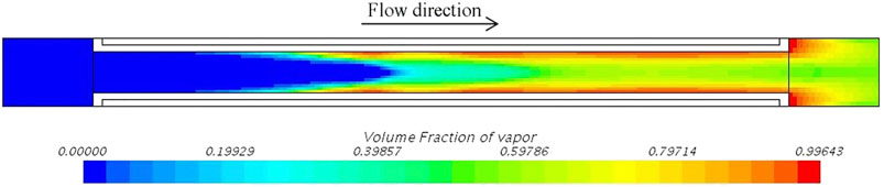
FIGURE 8. Void fraction distribution with 0.5 m/s inlet velocity (scale: x:z = 1:20).
Influence of Power Density
Figure 9 shows the coolant outlet temperature, maximum coolant temperature, maximum cladding temperature and maximum fuel temperature with the different uniform power density of the fuel. The inlet velocity was 4.5 m/s and the coolant inlet temperature was 35°C. The coolant temperature, the cladding temperature and the fuel temperature increase with the power density as shown in Figure 9. Since the maximum coolant temperature reaches above the saturation temperature with 9.40 × 10⁹ and 11.75 × 10⁹ W/m3 power density, the boiling phase change occurs. As shown in Figure 10, due to the high power density, the void fraction near the fuel plate at the rear of the flow channel was very large, which weaken the heat transfer and lead to higher maximum fuel temperature and higher maximum cladding temperature.
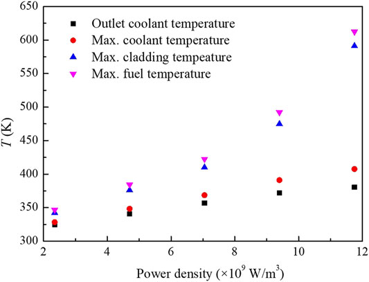
FIGURE 9. Temperature of coolant, cladding and fuel with different power densities.
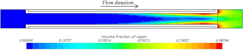
FIGURE 10. Void fraction distribution with 11.75 × 10⁹ W/m3 power density (scale: x:z = 1:20).
The influence of power density distribution on the conjugated heat transfer was numerically investigated. Three kinds of power density distributions along the height direction were used with the total power of the fuel plate maintained, as shown in Figure 11. Figure 12 shows the simulation results of the temperature distribution of the calculation region with qavg = 2.35 × 10⁹ W/m3. As shown in Figure 12, the coolant outlet temperatures were equal for these three cases due to the conservation of energy. The maximum temperature of the cladding and the fuel is the largest for q2 due to the concentrate distribution of the power density. The maximum cladding temperature and the maximum fuel temperature were lower for the uniform distribution of the power density. With the uniform power density distribution, the maximum temperature of the fuel plate appears at the rear due to the increase of the coolant temperature along the flow direction.
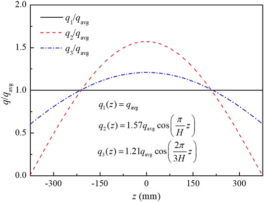
FIGURE 11. Power density distribution along the height direction.
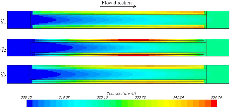
FIGURE 12. Temperature distribution with different power density distributions (scale: x:z = 1:20).
Influence of Channel Width
The conjugated heat transfer with different channel widths was simulated. In the simulations, the coolant inlet mass flux was maintained. Figure 13 shows the coolant outlet temperature, maximum coolant temperature, maximum cladding temperature and maximum fuel temperature with different channel widths, 1.75, 2.28 and 2.75 mm. Since the coolant inlet mass flux was maintained, the inlet velocities were 5.23, 4.50, and 4.00 m/s for these three cases, respectively. As shown in Figure 13, the coolant outlet temperature does not change with the channel width due to the conservation of energy. The maximum cladding temperature and maximum fuel temperature increase with the channel width. This is because, with the channel width increase, the coolant velocity decreases and the convective heat transfer weakens.

FIGURE 13. Temperature of coolant, cladding and fuel with different channel widths.
Conclusion
The conjugated heat transfer model between the plate-type fuel assembly and the coolant was established in this paper. With the RPI wall boiling model added into the Euler multi-phase flow method, the heat transfer and boiling phase change process in the whole fuel assembly and a single unit of the assembly of the research reactor were simulated. In the model validation, the simulated wall temperature variation, coolant temperature variation and void fraction variation were in good agreement with the experimental results in the literature.
The influence of the coolant inlet velocity, power density and flow channel width on the conjugated heat transfer was numerically investigated. According to the simulation results, the coolant outlet temperature, maximum coolant temperature, maximum cladding temperature and maximum fuel temperature increase with the decrease of the inlet velocity and increase with the increase of the fuel power density. Three kinds of power density along the axial direction were considered in this work. The maximum cladding temperature and the maximum fuel temperature were lower for the uniform distribution of the power density. As for the investigation of the influence of channel width on the conjugated heat transfer, the coolant inlet mass flux was maintained. The maximum cladding temperature and maximum fuel temperature increase with the increase of channel width.
Among the simulation conditions in this work, the boiling phase change occurs with 0.5 m/s inlet velocity under 2.35 × 10⁹ W/m3 power density, 4.5 m/s inlet velocity under 9.4 × 10⁹ W/m3 power density and 4.5 m/s inlet velocity under 11.75 × 10⁹ W/m3 power density. The maximum void fraction appears at the leeward of the plate and the rear of the flow channel near the plate.
Data Availability Statement
The raw data supporting the conclusions of this article will be made available by the authors, without undue reservation.
Author Contributions
QL: Conceptualization, Methodology, Investigation, Resources, Writing – Review & Editing; QM: Conceptualization, Methodology, Data curation, Writing – Original Draft, Writing – Review & Editing; YL: Conceptualization, Supervision; PC: Conceptualization, Supervision; CM: Data curation, Resources; BZ: Methodology, Data curation; HC: Methodology, Writing – Review & Editing.
Funding
This work was supported by the Youth Program of National Natural Science Foundation of China (No. 11805195).
Conflict of Interest
The authors declare that the research was conducted in the absence of any commercial or financial relationships that could be construed as a potential conflict of interest.
Publisher’s Note
All claims expressed in this article are solely those of the authors and do not necessarily represent those of their affiliated organizations, or those of the publisher, the editors and the reviewers. Any product that may be evaluated in this article, or claim that may be made by its manufacturer, is not guaranteed or endorsed by the publisher.
References
Anglart, H., and Nylund, O. (1996). CFD Application to Prediction of Void Distribution in Two-phase Bubbly Flows in Rod Bundles. Nucl. Eng. Des. 163 (1-2), 81–98. doi:10.1016/0029-5493(95)01160-9
Bartolemei, G. G., and Chanturiya, V. M. (1967). Experimental Study of True Void Fraction when Boiling Subcooled Water in Vertical Tubes. Therm. Eng. 14 (2), 123–128.
Cole, R. (1960). A Photographic Study of Pool Boiling in the Region of the Critical Heat Flux. Aiche J. 6, 533–538. doi:10.1002/aic.690060405
Deng, Y., Wu, Y., Zhang, D., Tian, W., Qiu, S., and Su, G. H. (2016). Development of a thermal-mechanical Behavior Coupling Analysis Code for a Dual-Cooled Annular Fuel Element in PWRs. Nucl. Eng. Des. 301, 353–365. doi:10.1016/j.nucengdes.2016.03.021
Gong, D., Huang, S., Wang, G., and Wang, K. (2015). Heat Transfer Calculation on Plate-type Fuel Assembly of High Flux Research Reactor. Science and Technology of Nuclear Installations, 198654. doi:10.1155/2015/198654
González Mantecón, J., and Mattar Neto, M. (2018). Numerical Methodology for Fluid-Structure Interaction Analysis of Nuclear Fuel Plates under Axial Flow Conditions. Nucl. Eng. Des. 333, 76–86. doi:10.1016/j.nucengdes.2018.04.009
Guo, Y., Wang, G., Qian, D., Yu, H., Hu, B., Guo, S., et al. (2018). Accident Safety Analysis of Flow Blockage in an Assembly in the JRR-3M Research Reactor Using System Code RELAP5 and CFD Code FLUENT. Ann. Nucl. Energ. 122, 125–136. doi:10.1016/j.anucene.2018.08.031
He, Y., Chen, P., Wu, Y., Su, G. H., Tian, W., and Qiu, S. (2018). Preliminary Evaluation of U 3 Si 2 -FeCrAl Fuel Performance in Light Water Reactors through a Multi-Physics Coupled Way. Nucl. Eng. Des. 328, 27–35. doi:10.1016/j.nucengdes.2017.12.019
Kumar, M., Moharana, A., Nayak, A. K., and Joshi, J. B. (2018). CFD Simulation of Boiling Flows inside Fuel Rod Bundle of a Natural Circulation BWR during SBO. Nucl. Eng. Des. 338, 300–329. doi:10.1016/j.nucengdes.2018.08.011
Kurul, N., and Podowski, M. (1991). “On the Modeling of Multidimensional Effects in Boiling Channels,” in Proceedings of the 27th National Heat Transfer Conference, Minneapolis, Minnesota, USA.
Lavieville, J., Quemerais, E., Mimouni, S., Méchitoua, N., and Boucker, M. (2005). Neptune CFD V1.0, Theory Manual. France: Electricite De France.
Lemmert, M., and Chawla, J. (1977). Influence of Flow Velocity on Surface Boiling Heat Transfer Coefficient. Heat Transfer Boiling, 237–247.
Li, Q., Avramova, M., Jiao, Y., Chen, P., Yu, J., Pu, Z., et al. (2018). CFD Prediction of Critical Heat Flux in Vertical Heated Tubes with Uniform and Non-uniform Heat Flux. Nucl. Eng. Des. 326, 403–412. doi:10.1016/j.nucengdes.2017.11.009
Li, Y., Li, W., Wan, L., Xi, Y., and Wang, N. (2020). Numerical Simulation of Boiling Two-phase Flow in the Subchannel under Static State and Rolling Motion. Int. J. Heat Mass Transfer 163, 120416. doi:10.1016/j.ijheatmasstransfer.2020.120416
Liao, H., Wang, Y., Li, Y., Wu, Y., Deng, Y., Su, M., et al. (2020). 3D Fluid-Solid Coupling Simulation for Plate-type Nuclear Fuel Assemblies under the Irradiation Condition. Prog. Nucl. Energ. 126, 203428. doi:10.1016/j.pnucene.2020.103428
Liu, R., and Zhou, W. (2017). Multiphysics Modeling of Novel UO2-BeO sandwich Fuel Performance in a Light Water Reactor. Ann. Nucl. Energ. 109, 298–309. doi:10.1016/j.anucene.2017.05.037
Lopez de Bertodano, M. (1991). “Turbulent Bubbly Flow in a Triangular Duct,”. Ph.D. Thesis (Troy, New York: Rensselaer Polytechnic Institute).
Lu, Q., Qiu, S., and Su, G. H. (2009). Flow Blockage Analysis of a Channel in a Typical Material Test Reactor Core. Nucl. Eng. Des. 239, 45–50. doi:10.1016/j.nucengdes.2008.06.016
Park, J.-P., Park, C., and Park, S. (2021). A Numerical Analysis for a Damage Propagation in a Plate-type Fuel Assembly of a Research Reactor. Ann. Nucl. Energ. 153, 108071. doi:10.1016/j.anucene.2020.108071
Phillippe, A. M., Ott, L., Clarno, K., and Banfield, J. (2012). Analysis of the IFA-432, IFA-597, and IFA-597 MOX Fuel Performance Experiments by FRAPCON-3.4. America: Oak Ridge National Laboratory.
Shirvan, K. (2016). Numerical Investigation of the Boiling Crisis for Helical Cruciform-Shaped Rods at High Pressures. Int. J. Multiphase Flow 83, 51–61. doi:10.1016/j.ijmultiphaseflow.2016.03.014
Son, H. M., Yang, S. H., Park, C., and Lee, B. C. (2015). Transient thermal-hydraulic Analysis of Complete Single Channel Blockage Accident of Generic 10 MW Research Reactor. Ann. Nucl. Energ. 75, 44–53. doi:10.1016/j.anucene.2014.08.002
Sun, R., Song, G., Zhang, D., Deng, J., Su, G. H., Kulacki, F. A., et al. (2020). Experimental Study of Single-phase Flow and Heat Transfer in Rectangular Channels under Uniform and Non-uniform Heating. Exp. Therm. Fluid Sci. 114, 110055. doi:10.1016/j.expthermflusci.2020.110055
Tolubinsky, V., and Kostanchuk, D. (1970). “Vapour Bubbles Growth Rate and Heat Transfer Intensity at Subcooled Water Boiling,” in Proceedings of the 4th International Heat Transfer Conference, Paris-Versailles, France, 31 August - 5 September. doi:10.1615/ihtc4.250
Tomiyama, A. (2004). “Drag Lift and Virtual Mass Forces Acting on a Single Bubble,” in Third International Symposium on Two- Phase Flow Modeling and Experimentation, Pisa, Italy, September 22-24.
Yoo, J., Oka, Y., Ishiwatari, Y., and Liu, J. (2006). Thermo-mechanical Analysis of Supercritical Pressure Light Water-Cooled Fast Reactor Fuel Rod by FEMAXI-6 Code. Ann. Nucl. Energ. 33, 1379–1390. doi:10.1016/j.anucene.2006.10.004
Zeitoun, O., and Shoukri, M. (1996). Bubble Behavior and Mean Diameter in Subcooled Flow Boiling. J. Heat Transfer 118, 110–116. doi:10.1115/1.2824023
Keywords: conjugated heat transfer, numerical simulation, plate-type fuel assembly, subcooled flow boiling, multi-phase flow
Citation: Li Q, Ma Q, Li Y, Chen P, Ma C, Zhao B and Chen H (2021) Numerical Investigation of Conjugated Heat Transfer of the Plate-Type Fuel Assembly in the Research Reactor. Front. Energy Res. 9:663533. doi: 10.3389/fenrg.2021.663533
Received: 03 February 2021; Accepted: 23 August 2021;
Published: 21 September 2021.
Edited by:
Yingwei Wu, Xi’an Jiaotong University, ChinaReviewed by:
Boštjan Končar, Institut Jožef Stefan (IJS), SloveniaMarco Colombo, University of Leeds, United Kingdom
Deqi Chen, Chongqing University, China
Copyright © 2021 Li, Ma, Li, Chen, Ma, Zhao and Chen. This is an open-access article distributed under the terms of the Creative Commons Attribution License (CC BY). The use, distribution or reproduction in other forums is permitted, provided the original author(s) and the copyright owner(s) are credited and that the original publication in this journal is cited, in accordance with accepted academic practice. No use, distribution or reproduction is permitted which does not comply with these terms.
*Correspondence: Yuanming Li, bHltX25waWNAMTI2LmNvbQ==; Ping Chen, Y2hlbnBpbmdfbnBpY0AxNjMuY29t