 Xiaojing Li
 Yu Ma
Yu Ma Wenzhong Zhou
 Zhao Liu
- Sino-French Institute of Nuclear Engineering and Technology, Sun Yat-Sen University, Zhuhai, China
FeCrAl alloys are promising accident-tolerant fuel (ATF) cladding materials for applications in light water reactors (LWRs). Despite the excellent mechanical and antioxidation properties, this series of iron-based alloys has poor hydrogen embrittlement (HE) resistance due to the strong hydrogen uptaking ability. The hydrogen embrittlement effect can cause the degradation and premature failure of the material, and this effect can be enhanced by the high-temperature/high-pressure/high-irradiation environment in reactors. So, the potential danger should be taken seriously. In this paper, we have studied the hydrogen atom and molecule adsorptions on both Fe (100) and FeCrAl (100) surfaces to discover how the hydrogen atom and molecule (H/H2) interact with the Fe and FeCrAl (100) surface in the first place. The results show that there are strong element effects on the FeCrAl surface. The Al atom itself has no interaction with hydrogen. When the Al atom is beside the Fe atom, this Fe atom has a slightly lower interaction with hydrogen. However, the Al atom beside the Cr atom will enhance the hydrogen interaction with this Cr atom. On the other hand, when the Cr atom is beside the Fe atom, these two atoms (Fe–Cr bridge site) can reduce the interactions with H. In addition, when two Cr and two Fe atoms together make a four-fold site (FF site), the two Cr atoms can increase the interaction of the two Fe atoms with H. The element effects discovered can be a good guide for making hydrogen prevention coatings.
Introduction
Hydrogen embrittlement (HE) can cause a reduction in the tensile strength, ductility, fracture strength, and toughness of materials (Shen, 2010; Seki et al., 2012; Dwivedi and Vishwakarma, 2021). For safety reasons, the degradation of material mechanical properties caused by HE cannot be ignored, especially under the extreme operating conditions in nuclear reactors (Harries and Broomfield, 1963; Koutsky, 1990). Generally, there are two kinds of HE (Qian and Atrens, 2013; Popov et al., 2018; Dwivedi and Vishwakarma, 2021): 1) internal HE, which is caused by hydrogen introduced through the fabrication process, such as acid cleaning, electroplating, protective coatings, and welding and 2) external HE, which is caused by hydrogen sourcing from the working environment. When interacting with metal and alloy surfaces, a hydrogen molecule can dissociate into two hydrogen atoms and then adsorb on the surfaces (Johnson and Carter, 2010; Zhang et al., 2013). Due to the high mobility and chemical reactivity, the hydrogen atoms would permeate the surface and tend to aggregate inside the materials at defects, dislocations, voids, grain/phase boundaries, microcracks, precipitates, interfaces, and so on (Dwivedi and Vishwakarma, 2021). The aggregated hydrogen atoms may form brittle hydrides with the alloy compositions and form hydrogen molecules again (Dwivedi and Vishwakarma, 2018). All these together will cause the local swelling and formation of microcracks. When under stress, the cracks will propagate and lead to the failure of materials (Chernov et al., 2017; Popov et al., 2018; Robertson et al., 2015; Li et al., 2020). In the present work, we focused on the external HE. So far, many HE mechanisms had been developed to explain HE, such as hydrogen-enhanced decohesion mechanism (HED) (Pfeil, 1926), hydrogen-induced phase transformation mechanism (HIPT) (Westlake, 1969), adsorption-induced dislocation emission mechanism (AIDE) (Lynch, 1979), hydrogen-enhanced localized plasticity mechanism (HELP) (Birnbaum and Sofronis, 1994), and hydrogen-enhanced strain-induced vacancies (HESIV) (Nagumo, 2001; 2004). The HED mechanism postulates that hydrogen can decrease the strength of metal bonds, so that the material will break under lower tensile strength. The HIPT mechanism focuses on the formation of hydrides. Westlake (1969) found that the brittle hydrides promote crack growth, and the cracks will stop at the interface between hydrides and the matrix. However, when more hydrogen accumulates at the crack tip, the process will start again. The AIDE mechanism had been proposed in the 1970s. It hypothesizes that hydrogen at the crack tip will accelerate the dislocation emission. In addition, when there are microvoids ahead of the crack, the crack will grow to merge with microvoids. The HELP mechanism states that hydrogen will aggregate to dislocations and facilitates the motion of dislocations, which will, in turn, cause dislocation pileups and localized plasticity of materials. The HESIV mechanism suggests that hydrogen promotes the aggregation of vacancies to make microvoids, decreasing the ductility of materials.
However, there is no universal theory to explain the HE behavior for all the materials among all the mechanisms proposed. So, it is necessary to study hydrogen embrittlement on certain materials. FeCrAl alloys are among them because they are considered as the promising accident-tolerant fuel (ATF) cladding candidates for light water reactors (LWRs) due to their excellent properties (Wang et al., 2018). The cladding gets in contact with hydrogen when under service conditions. Thus, the HE problem should be taken into consideration. In light water reactors (LWRs), hydrogen can be generated in many ways (Müller et al., 2006; Roychowdhury et al., 2016; Chernov et al., 2017): 1) the corrosion reactions between metal alloys (cladding and other structural materials) and the coolant under the high-pressure and -irradiation environment; 2) water radiolysis; 3) hydrogen additions to inhibit water radiolysis and oxidation caused by oxidative radicals; and so on.
Since hydrogen adsorption is the initial step for the HE process, it is necessary to study how hydrogen interacts with FeCrAl. If we get enough information about how hydrogen interacts with the surface atom in the very first place, prevention methods may be found to decrease hydrogen adsorption and then weaken the hydrogen embrittlement effect. Although the potential application of FeCrAl alloy for ATF cladding material and HE’s crucial effect on it are well known, there are not enough experimental and theoretical studies about how hydrogen interacts with the FeCrAl alloy surface. One of the reasons is that it is pretty challenging to obtain experimental results on the microscopic level owing to the lack of effective detection instruments (Zhang et al., 2013). However, many microscopic simulations can offer a microscopic insight into how hydrogen interacts with the material, such as Density Functional Theory (DFT) and Molecular Dynamics (MD) simulations. They have been used to study hydrogen embrittlement on various materials and have been proven to be successful (Shen, 2010; Peng, 2011; Seki et al., 2012; Bitzek et al., 2015; Ma et al., 2015; Timmerscheidt et al., 2017). In our work, the DFT method had been employed to study hydrogen adsorption on FeCrAl alloy’s low-index surface [in this case, the (100) surface]. For cubic crystal structures such as FeCrAl, the low-index plane is more likely to expose in practical experimentation owing to its low surface energy. Therefore, exposure to low-index surfaces can stabilize the whole structure (Liu et al., 2017). Thus, the study of the low-index surface is of great significance.
There already are DFT studies about hydrogen adsorption on the low-index surfaces of pure iron. Sorescu (2005) studied H/H2 adsorption on Fe (100) surfaces using 2 × 2 six- or seven-layer slabs. The hydrogen molecule and atom were put parallel to the surface with different initial heights. He found that, within the distance range of around 0.75–1.5 Å, the hydrogen molecule would dissociate and then be adsorbed on the surface at the two adjacent bridge sites or two four-fold sites. He also discovered that hydrogen atoms preferred being adsorbed at the bridge site (adsorption energy is ∼ −2.64 eV) and four-fold sites (adsorption energy is ∼ −2.68 eV). However, no DFT calculations were performed directly to investigate hydrogen adsorption on FeCrAl alloy’s low-index surfaces. This paper conducted a series of DFT studies investigating single hydrogen atom and molecule adsorption on the FeCrAl (100) surface. We aim to study how different atoms interact with H/H2 and how the surrounding atoms affect this interaction. In order to make a comparison, the H/H2 adsorption on a pure Fe (100) surface was also studied. The results of single H adsorption on Fe (100) are similar to the DFT results of Sorescu (2005). However, when a hydrogen molecule is put perpendicular instead of parallel to the surface, the molecule will not dissociate and is adsorbed only physically, as discussed in H2 Adsorption on Fe (100) and FeCrAl (100). The calculations of hydrogen adsorption on FeCrAl (100) revealed the same trend as the H/H2 adsorption on the Fe (100) surface. However, there are still some differences between Fe and FeCrAl (100) surfaces due to the effect of Cr and Al elements on the H/H2 interaction.
Methods
All the first-principle calculations were performed to investigate the hydrogen adsorption on the FeCrAl alloy and pure iron (100) surface with different preadsorbed sites based on spin-polarized periodic density functional theory (DFT) (Hohenberg and Kohn, 1964; Kohn and Sham, 1965) using Vienna Ab-initio Simulation Package (VASP) (Kresse and Furthmüller, 1996). The calculations for both FeCrAl and Fe were performed with the projector augmented wave (PAW) pseudopotential and the spin-polarized generalized gradient approximation (GGA), which were implemented to describe the electron–ion interactions (Blöchl, 1994; Kresse and Joubert, 1999) and the exchange-correlation energies (Perdew et al.,1996), respectively. To make the results comparable, all the parameters remained the same for these two systems. The (3 × 3 × 3) kpoints in the Brillouin zone (BZ) were all generated by a Gamma-centered scheme, and the cutoff energy was set at 400 eV after a convergence test. The bulk and slabs were allowed to relax until the residue force and total energy difference fell below 0.015 eV/Å and 10−6 eV, respectively.
A (3 × 3 × 3) supercell of body-center cubic structure (BCC) Fe bulk and (3 × 3) slabs with seven layers were used. The FeCrAl bulk used was a (3 × 3 × 3) supercell with 54 atoms, in which a part of BCC Fe atoms was replaced by ∼20.4 wt% Cr atoms and ∼5.5 wt% Al atoms randomly using the Special Quasirandom Structures (SQSs) method (Zunger et al., 1990; Van de Walle et al., 2013). This Cr and Al composition is derived from commercial FeCrAl alloy APMT (21 wt% Cr, 5 wt% Al), which also has a BCC structure because this alloy has good mechanical properties (Terrani et al., 2014) and better high-temperature oxidation resistance than the lean commercial FeCrAl alloys (such as 13 wt% Cr, 4 wt% Al) (Pint et al., 2013; Terrani, 2018). The slabs were (3 × 3) slabs, and the number of layers was set at 7. During optimization, the bottom two layers were fixed and the top five layers were allowed to be relaxed for both systems. The adsorption energy was calculated by the following equation:
Results and Discussion
H2/Fe/FeCrAl Bulk and Slab Relaxation
The Fe and FeCrAl (3 × 3 × 3) supercell were fully relaxed. As shown in Figure 1A, the equilibrium lattice constant for Fe is 8.48 Å (i.e., 2.83 Å for a primitive cell), which is close to a series of DFT results (2.83–2.87 Å) and experimental data (2.87 Å) (Jiang and Carter, 2003; Sorescu, 2005; D. C.; Sorescu et al., 2002). Furthermore, comparing with bulk values, the interlayer distance between first and second layers (d1-2) is compressed with the ratio to bulk value of −2.0%, while the distance between second and third layers (d2-3) is expanded with the ratio to bulk value of 3.0%, which is again in accordance with the trend of other previous studies (Eder and Hafner, 2001; Sorescu, 2005). Moreover, a single hydrogen molecule is put in the center of a (10 Å × 10 Å × 10 Å) vacuum cubic. After optimization, the distance of the H–H bond is 0.75Å. The result is the same with DFT calculations (0.75Å) and similar to the experimental result (0.74Å) (Sorescu, 2005). So, the modeling results of Fe bulk and H2 indicate the accuracy and the feasibility of this method. Figure 1B is the bulk and (100) slab of FeCrAl. The equilibrium lattice constant is slightly increased to 8.52 Å (i.e., 2.84 Å for a primitive cell), and there is also a slight distortion of the structure. However, it is reasonable because of the difference in atomic radii (Fe 1.26 Å, Cr 1.27 Å, and Al 1.43 Å). Besides, the same inclination of compression of d1–2 (ratio to bulk value is −1.5%) and expansion of d2–3 (ratio to bulk value is 1.9%) is also found, suggesting the rationality of the calculations.
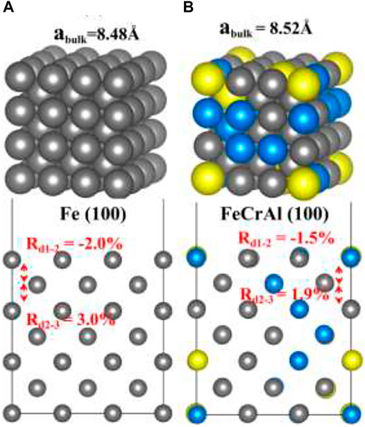
FIGURE 1. The optimized structures of Fe and FeCrAl: (A) bulk and (100) slab of Fe; (B) bulk and (100) slab of FeCrAl (hereinafter dark grey atoms are Fe, blue atoms are Cr, and yellow atoms are Al).
H Adsorption on Fe (100) and FeCrAl (100)
As shown in Figure 2A, the initial top, bridge (B), and four-fold (FF) sites of H adsorption on the Fe (100) surface were investigated. According to Sorescu (2005), within the distance range of around 0.75–1.5 Å, the hydrogen molecule would dissociate and then be adsorbed on the surface. So, we choose to put the H atom (the same for the H2 molecule in H2 Adsorption on Fe (100) and FeCrAl (100)) 1 Å above the surface sites at the beginning so that the H can interact with the surface atom effectively and efficiently. The corresponding configurations after optimization are provided in Supplementary Figure S1. As shown, top-site H was adsorbed at the neighboring bridge site (also shown in Figure 3A) with an adsorption energy of −3.72 eV (Table 1) because the top site is not stable (Sorescu, 2005). The B-site H and FF-site H were both adsorbed at the original B site with 1.12 Å above the surface and FF site with 0.37 Å above the surface, respectively. The relaxed configurations are very close to the previous DFT data calculated using PW91-USPP (1.063 Å for the B site and 0.382 Å for the FF site) and PAW potentials (1.061 Å for the B site and 0.376 Å for the FF site) (Sorescu, 2005). In addition, the adsorption energies of B sites listed in Table 1 are both −3.72 eV and of the FF site is −3.75 eV. The adsorption energy difference of B and FF sites is 0.03 eV, which is also very similar to the results (Sorescu, 2005). The agreements of our results with other DFT data justified our calculations. The charge density difference and DOS results in Figures 3B,C exhibit identical charge transfer and s/d orbital changes, and they fit perfectly with each other. In Figure 3B, the red color represents charge accumulation and the green color represents charge depletion. There is charge transfer from surface Fe atoms to the H atom, and the DOS results show that the s and d orbitals interact stronger with H than the p orbital, which indicates that the bond formed through the H 1s orbital and Fe 4s and 3d orbital.
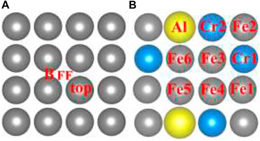
FIGURE 2. The initial sites of the hydrogen atom and molecule (H/H2) on the Fe and FeCrAl (100) surface.
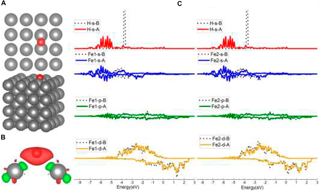
FIGURE 3. The optimized structure, charge density difference, and density of state (DOS) of the top site after the hydrogen atom is adsorbed on the Fe (100) surface: (A) top and side view of the H-slab structure (hereinafter dark grey atoms are Fe and red atoms are H), (B) charge density difference (the isosurface of charge difference is 0.007 electrons/Bohr3), red color represents charge accumulation, and green color represents charge depletion, and (C) density of state (DOS) before and after H atom adsorption, the black dotted lines represent s/p/d orbitals before H adsorption, and B/A represents before and after, respectively.
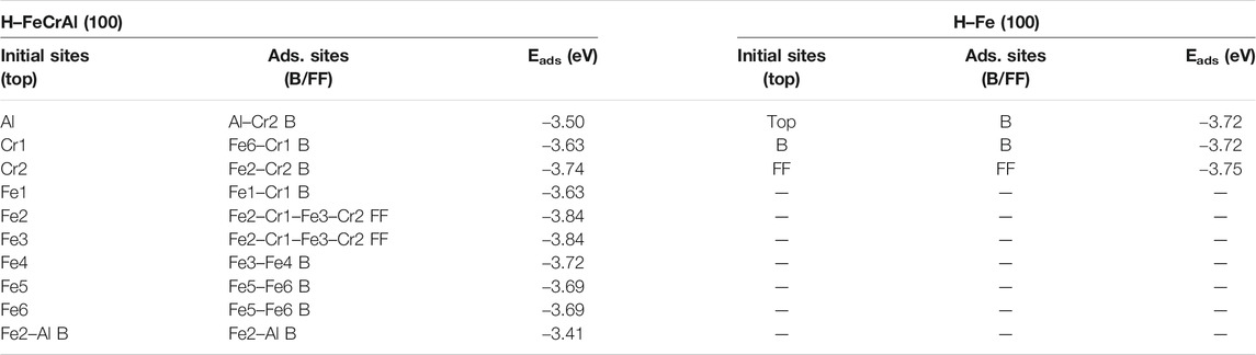
TABLE 1. Adsorption energies of the H atom on the Fe (100) and FeCrAl (100) surface.
For the FF-site case, when initially put in the center of the FF site, H was adsorbed at the FF site and tilted slightly to Fe3 and Fe4, as indicated in Figures 4A,B. In Figure 4B, there is noticeably more charge transfer from Fe3/Fe4/Fe-sec (the second-layer Fe) than Fe1/Fe2, suggesting stronger interactions between H and Fe3/Fe4/Fe-sec, and the DOS in Supplementary Figure S2 has also demonstrated this. Figure 4C lists the s/p/d orbital changes of Fe3, Fe4, and the second-layer Fe (Fe-sec) before and after H adsorption. The s/p/d orbital changes show that H interacts with the second-layer Fe the most, for there is a strongest s orbital change of Fe-sec than the change of Fe3/Fe4, which is in conformity with the slightly higher adsorption energy of the FF site than the B site.
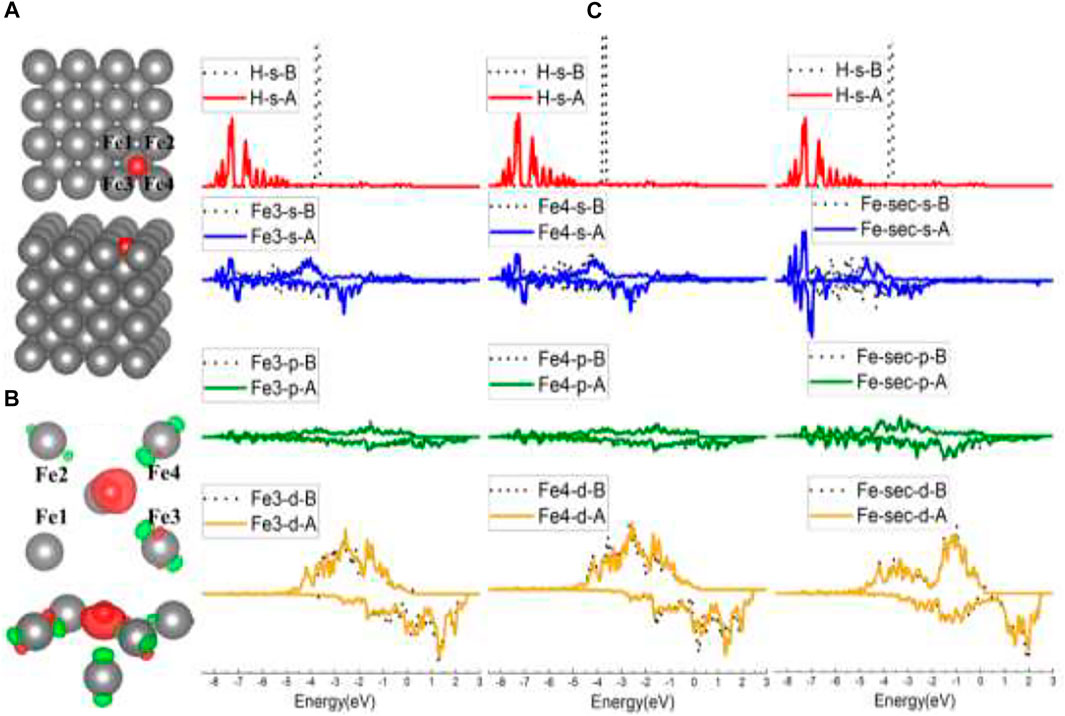
FIGURE 4. The optimized structure, charge density difference, and DOS of the four-fold site after the hydrogen atom is adsorbed on the Fe (100) surface: (A) top and side view of the H-slab structure, (B) charge density difference (the isosurface of charge difference is 0.007 electrons/Bohr3), red color represents charge accumulation, and green color represents charge depletion, and (C) DOS before and after H atom adsorption, the black dotted lines represent s/p/d orbitals before H atom adsorption, and B/A represents before and after, respectively.
To compare with Fe (100) and find out how different atoms (Fe, Cr, and Al) interact with H, nine preliminary top sites were studied on the FeCrAl (100) surface, as presented in Figure 2B. Before relaxation, the H atom was also put 1 Å above the nine atoms labeled in Figure 2B. The corresponding configurations after adsorption are provided in Supplementary Figure S3. In the previous discussion, the H on Fe (100) was only adsorbed at the B site, while the H on FeCrAl (100) prefers to be attracted both at the bridge (B) and four-fold site (FF) when interacting with different atoms. So, from the difference of H adsorption on Fe and FeCrAl (100) surfaces, surface element effects can be deduced.
When put on top of Fe4/Fe5/Fe6 (Figure 2B), H atoms were also captured at Fe–Fe B sites. Even though the charge transfer in Figure 5B is highly symmetric, the s/p/d orbital changes in Figure 5C are not strictly as symmetric as the B site on the Fe (100) surface because of the effect of randomly distributed different surface atoms. The s and d orbital shifts suggest that bonds have been created between H 1s and Fe 4s and 3d orbitals, consistent with the B site of Fe (100) results. However, the adsorption energy for the Fe–Fe B site consisting of Fe5/Fe6 and Fe3/Fe4 is different (shown in Table 1), which is caused by the element effect and will be discussed in the following Al-top part.
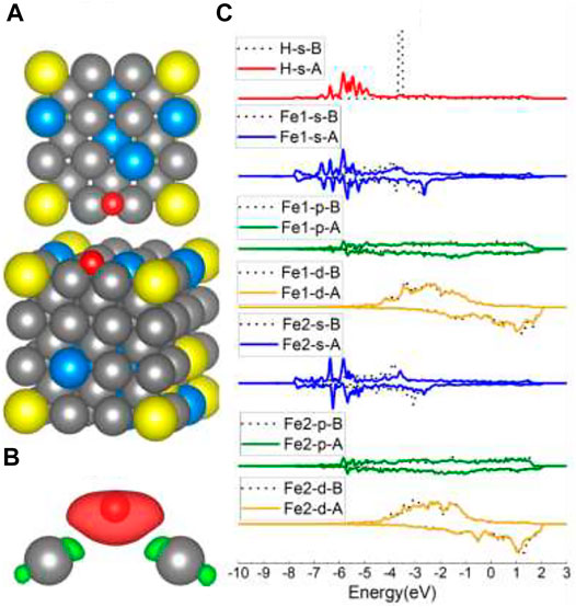
FIGURE 5. The optimized structure, charge density difference, and DOS of the Fe–Fe bridge site after the hydrogen atom is adsorbed on the FeCrAl (100) surface: (A) top and side view of the H-slab structure, (B) charge density difference (the isosurface of charge difference is 0.007 electrons/Bohr3), red color represents charge accumulation, and green color represents charge depletion, and (C) DOS before and after H atom adsorption, the black dotted lines represent s/p/d orbitals before H atom adsorption, and B/A represents before and after, respectively.
For Fe1, Cr1, and Cr2 models, the H atoms tended to occupy the adjacent Fe–Cr B sites. According to the adsorption energy in Table 1, the values vary from −3.63 eV to −3.74 eV, which is also caused by the different atom circumstances. Compared with the adsorption energy of the B site on Fe (100) (−3.72 eV), the one Cr atom in the Fe–Cr B site did not increase the interaction between H and the surface. Sometimes the existence of one Cr atom in the B site can even lower the interactions. This phenomenon will also be discussed later in the Al-case part. The charge density shapes of the Fe–Cr B site shown in Figure 6B lost the prior symmetry for the Fe–Fe B site as a result of the asymmetry of the site. The DOS results of Fe/Cr in Figure 6C show that the 4s and 3d orbitals shifted more comparing with 3p orbitals, which is the same with Fe in the Fe–Fe B site. The bond has also been formed through the H 1s orbital and Fe 4s and 3d orbital.
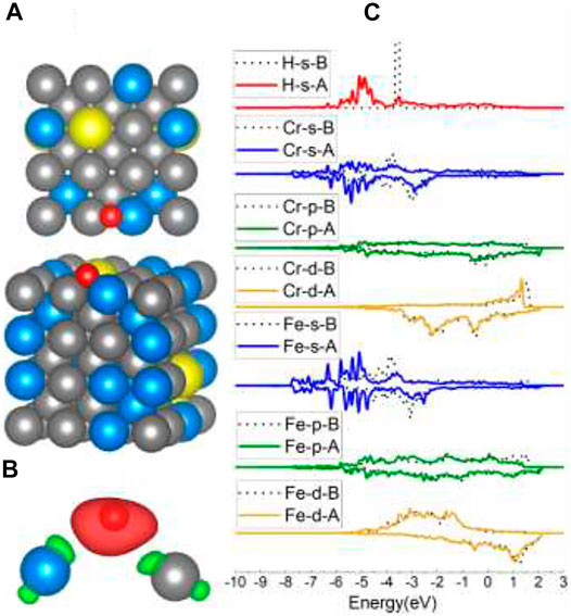
FIGURE 6. The optimized structure, charge density difference, and DOS of the Fe–Cr bridge site after the hydrogen atom is adsorbed on the FeCrAl (100) surface: (A) top and side view of the H-slab structure, (B) charge density difference (the isosurface of charge difference is 0.007 electrons/Bohr3), red color represents charge accumulation, and green color represents charge depletion, and (C) DOS before and after H atom adsorption, the black dotted lines represent s/p/d orbitals before H atom adsorption, and B/A represents before and after, respectively.
Typically, when put on the top of surface atoms, H will be adsorbed at the B site, as for the top site of Fe and Fe1 Cr1, Cr2, Fe4, Fe5, Fe6 models of FeCrAl. However, after interaction with Fe2 and Fe3, H atoms were attracted at the same neighboring Fe2–Cr1–Fe3–Cr2 FF site, as shown in Figure 7A. The adsorption energy of this FF site is the lowest (listed in Table 1), which means that it is the most stable among all the FeCrAl sites. Given that there are two Cr atoms around Fe2 and Fe3, the stronger interactions must be caused by the two Cr atoms. In addition, compared with the adjoining FF sites of the other seven atoms, this Fe–Cr–Fe–Cr FF site is apparently with high coordination. So, the H atom is more likely to be attracted at a high-coordinate site, consistent with the experimental and DFT conclusions (Baró and Erley, 1981; Jiang and Carter, 2003).
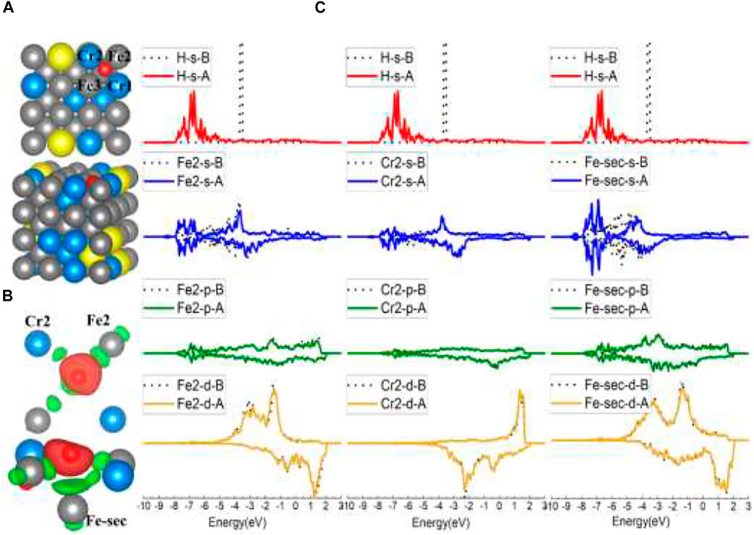
FIGURE 7. The optimized structure, charge density difference, and DOS of the Fe–Cr–Fe–Cr four-fold site after the hydrogen atom is adsorbed on the FeCrAl (100) surface: (A) top and side view of the H-slab structure, (B) charge density difference (the isosurface of charge difference is 0.007 electrons/Bohr3), red color represents charge accumulation, and green color represents charge depletion, and (C) DOS before and after H atom adsorption, the black dotted lines represent s/p/d orbitals before H atom adsorption, and B/A represents before and after, respectively.
Comparing this Fe2–Cr1–Fe3–Cr2 FF site with the FF site on Fe (100), there are similarities between the configurations. One is that both the FF sites are more stable than B sites. The clues can be found in the adsorption energy and DOS comparison in Table 1 and Figures 4C, 7C, which show that H interacts more strongly with the second-layer atom (Fe-sec). The other show that H atoms both lean closer to two of the atoms in the FF site (in the Fe case of Fe3 and Fe4, shown in Figures 4A,B; in the FeCrAl case of Fe2 and Cr2, shown in Figures 7A,B), instead of sitting at the center of the two FF sites.
However, there are differences as well. Since there are high-coordinating Fe–Fe–Fe–Fe FF sites nearby, the H atom on the Fe (100) surface has not been adsorbed at the adjacent FF site (as shown in Figure 3A, H was only adsorbed at the B site in the top model case) like the H atom on FeCrAl (100) has done. So, it further demonstrates that the two Cr atoms in the FF site can significantly enhance the interaction between H and the site, which is reasonable because the adsorption energy of the Fe–Cr–Fe–Cr FF site is lower than the Fe FF site’s (as listed in Table 1).
In the case of Al-top, H occupied the nearby Al–Cr B site instead of the adjoining Al–Fe B sites. It can be inferred that the Al–Fe B site is less stable than the Al–Cr B site, which is also confirmed by the adsorption energy of the Fe–Al B site listed in Table 1. Besides, the corresponding adsorption energy (−3.50 eV) of the Al–Cr and (−3.41 eV) Al–Fe B site is higher than that of the Fe–Cr B site (−3.63∼ −3.74 eV) and Fe–Fe B site (−3.69 ∼ −3.72) listed in Table 1, demonstrating that the Al atom in the B site can decrease the interaction between H and the B site. The charge density difference in Figure 8B clearly shows no charge transfer from Al to H, which confirms that Al has a weak interaction with H, in concordance with DOS results of Al in Figure 8C. It is worth noting that the interaction between Cr and H in the Al–Cr B site is much different than in the Fe–Cr and Fe–Cr–Fe–Cr sites, for there are more charge transfer and obvious 4s and 3d changes, indicating stronger interaction than in previous cases. So, we can infer that the Al atom in the Al–Cr2 B site can increase the interaction between Cr2 and H. Thus, the lower adsorption energy for the Fe–Cr2 B site (−3.74 eV and 0.11 eV significantly lower than that of the other two Fe–Cr1 B sites) in the Cr2 case is reasonable. Compared with the Fe–Fe B site on Fe (100), the adsorption energies of the other 2 Fe–Cr1 sites are 0.09 eV higher, suggesting that one Cr atom in the B site can decrease the interaction between H and the B site, while in the Fe4 model, the adsorption energy is the same as that of the Fe–Fe B site on Fe (100), which means that the Cr atom in the same line of the Fe–Fe site beside it has no influence on its stability. However, when there is an Al atom in the same line of the Fe–Fe site adjoining to it (as shown in the Fe5/Fe6 model in Figure 2), the adsorption energy becomes slightly higher (0.03 eV higher) than that of the Fe–Fe B site of Fe, indicating that the Al atom nearby in the same line of the Fe–Fe site probably weakens the interaction between H and the Fe–Fe B site a little. There is also a clue in the charge density shape change shown in Figures 3B, 5B. The Fe5/Fe6 cases have slightly lesser charge density change than the B site on Fe (100). Furthermore, the decreased 0.11 eV energy of the Fe–Cr2 B site and the increased 0.03 eV energy of the Fe5–Fe6 B site reflect that there is more substantial reinforced influence on the Fe–Cr2 site than weakening influence on the Fe5–Fe6 site of Al. For the Fe–Cr2 site and Fe–Cr–Fe–Cr site, the corresponding 0.11 and 0.09 eV lower energies show that the Al atom has a little more impact on the Fe–Cr2 site than the two Cr atoms together have on the Fe–Cr–Fe–Cr site.
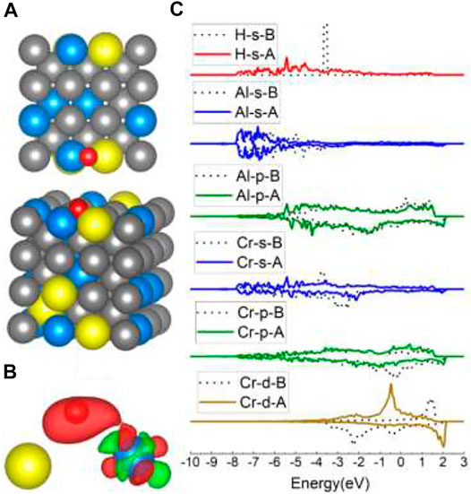
FIGURE 8. The optimized structure, charge density difference, and DOS of the Al–Cr bridge site after the hydrogen atom is adsorbed on the FeCrAl (100) surface: (A) top and side view of the H-slab structure, (B) charge density difference (the isosurface of charge difference is 0.007 electrons/Bohr3), red color represents charge accumulation, and green color represents charge depletion, and (C) DOS before and after H atom adsorption, the black dotted lines represent s/p/d orbitals before H atom adsorption, and B/A represents before and after, respectively.
H2 Adsorption on Fe (100) and FeCrAl (100)
Hydrogen molecule adsorption calculations were also conducted for both Fe and FeCrAl. Before optimization, a hydrogen molecule was set perpendicular to the surface 1 Å right above the atom. All the calculation parameters were kept constant to make the results comparable. The same three sites for Fe and nine sites for FeCrAl were studied, as shown in Figure 2.
Although when contacting with the Fe (100) surface horizontally, there is dissociation adsorption and this phenomenon was proved by Sorescu (2005), the results of Fe show that the hydrogen molecule has no dissociation adsorption when contacting with the surface perpendicularly in all the three models. The adsorption energy in Table 2, the optimized structures, and the corresponding DOS in SI Figure 5 support this. The structures show that H2 is ∼2.9 Å away from the surface and the H–H distances, around 0.754 Å, only have tiny expansion (H2 is 0.75 Å). Additionally, there is not electron delocalization in DOS, indicating physical interaction of H2 with the surface. The lesser contact with the surface might be the reason that leads to the corresponding weak interaction.
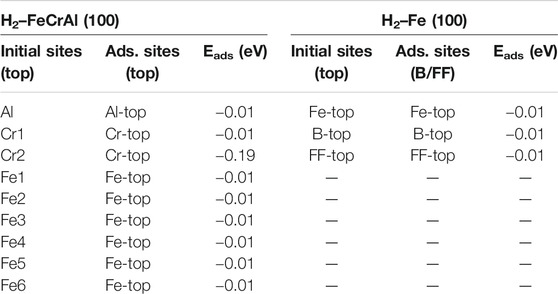
TABLE 2. Adsorption energies of the H2 molecule on the Fe (100) and FeCrAl (100) surface.
Similar results have also been found on the FeCrAl (100) surface. The nine optimized structures are offered in SI in Figure 6. Moreover, the energy reduction for the nine-model system after adsorption listed in Table 2 suggests that the interaction between H2 and the surface is tiny. However, according to the adsorption energy, there is a stronger interaction in model Cr2 than the rest. It is rational, for the paralleled hydrogen molecule has a larger interaction area and closer contact with the surface, as shown in Figure 9. Furthermore, the s and d orbital shifts of Cr2 can be seen in Figure 9 through the DOS, which also verified this. As discussed before in the model Al section, the Al atom beside Cr2 has an impact on the interaction between Cr2 and H. The strong influence has also impacted the interaction between Cr2 and H2.
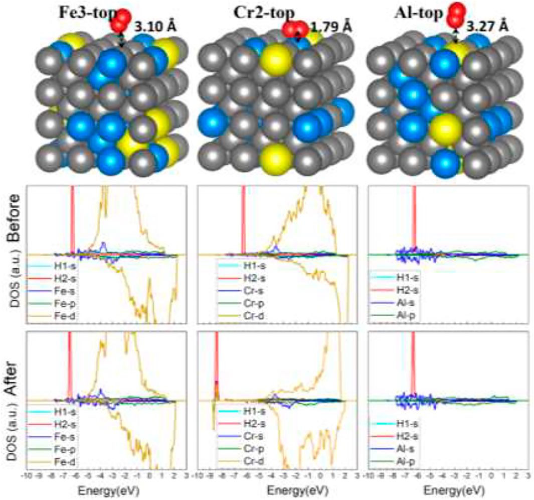
FIGURE 9. The optimized structures and DOS of H2–FeCrAl (100) slabs (three representative adsorption sites: Fe2-top, Cr2-top, and Al-top).
On the other hand, the 2 Cr atoms around Fe2/Fe3 have no influence on the H2 adsorption behavior with Fe, indicating Al has more impact on the adsorption behavior of adjacent Cr atoms than two Cr atoms together on Fe. This is consistent with the previous conclusions.
Conclusion
From all the discussions above, several conclusions can be derived:
1) There are strong effects of Al and Cr on the FeCrAl (100) surface. The Al atom has the weakest interaction with hydrogen itself, and it can also slightly weaken the adsorption stability of the Fe–Fe bridge site when it is beside the Fe atom on the same line with this Fe–Fe bridge site (labeled as Al-Ⅰ). However, when the Al atom is in the Al–Cr bridge site, it can significantly increase the interaction of Cr with a hydrogen atom and molecular (H/H2) (labeled as Al-Ⅱ). Similarly, when the Al atom is alongside the Cr atom on the same line with the Fe–Cr bridge site, the interaction of this Fe–Cr bridge site with H can be enhanced (labeled as Al-Ⅲ). Nonetheless, when there is no Al atom nearby, the Cr atom within the Fe–Cr bridge site can reduce the interaction of this Fe–Cr bridge site with H (labeled as Cr-Ⅳ). Moreover, the Cr atom adjacent to and on the extension line of the Fe–Fe bridge site has no influence on the stability of this Fe–Fe bridge site (labeled as Cr-Ⅴ). However, when two Cr atoms together consist of a coordinate four-fold site, this four-fold site is the most stable (labeled as 2Cr-Ⅵ). Among all the models studied, the influence intensity can be ordered as follows (as labeled above): Al-Ⅱ ∼ Al-Ⅲ (+0.11 eV) > Cr-IV (−0.09 eV) = 2Cr-VI (+0.09 eV) > Al-I (−0.03 eV) > Cr-V (0 eV). The labels “Al-” and “Cr-” mean the effect of Al and Cr, respectively. The numbers in the brackets indicate the adsorption energy change. “+” represents the enhanced interaction with H, while “−” represents the opposite.
2) When putting the H atom on top of the surface atoms, the hydrogen atom on Fe (100) is only adsorbed at the bridge site. Generally, the hydrogen atom on FeCrAl (100) would also favor the bridge site. However, due to the effect of two Cr atoms within the coordinate four-fold site, the hydrogen atom on FeCrAl (100) is more likely to be adsorbed at the Fe–Cr–Fe–Cr four-fold site.
3) The hydrogen molecule (H2) will not dissociate when contacting the atoms from the top site on Fe and FeCrAl (100) surface perpendicularly, even under the reinforced effect of Al and Cr atoms.
It is worth noting that hydrogen has a very weak interaction with the Al atom, but the interaction between Cr and H would be enhanced when Al is beside the Cr atom. When there is no Al by the side, one Cr with Fe can also decrease the interaction between the hydrogen atom and the surface. So, if the Al content on the surface could be selectively increased to some extent, the adsorption of H could be reduced. Furthermore, separating the Cr and Al atoms to make them far enough to each other would lower the enhanced effect of Al on Cr and, at the same time, decrease the hydrogen adsorption chance. In addition, if the Cr and Al atoms could be separate and kept far enough successfully, an appropriate increase of Cr content could also decrease hydrogen adsorption. According to this, a special surface could possibly be designed to reduce hydrogen adsorption and, thus, weaken the hydrogen embrittlement effect.
Data Availability Statement
The raw data supporting the conclusions of this article will be made available by the authors, without undue reservation.
Author Contributions
The work was mainly carried out by XL. ZL contributed to the accomplishment of this work, and WZ and YM are the advisors of XL.
Funding
This work was supported by the Nuclear Power Technology Innovation Center of China (No. 45000-41020012), NSAF (No. U1830118), and NSFC (No. 12002402) which are highly appreciated. This work was also supported by the Fundamental Research Funds for the Central Universities (No. 20lgpy186).
Conflict of Interest
The authors declare that the research was conducted in the absence of any commercial or financial relationships that could be construed as a potential conflict of interest.
Publisher’s Note
All claims expressed in this article are solely those of the authors and do not necessarily represent those of their affiliated organizations, or those of the publisher, the editors and the reviewers. Any product that may be evaluated in this article, or claim that may be made by its manufacturer, is not guaranteed or endorsed by the publisher.
Supplementary Material
The Supplementary Material for this article can be found online at: https://www.frontiersin.org/articles/10.3389/fenrg.2021.713493/full#supplementary-material
References
Baró, A. M., and Erley, W. (1981). The Chemisorption of Hydrogen on a (110) Iron crystal Studied by Vibrational Spectroscopy (EELS). Surf. Sci. 112 (1-2), L759–L764. doi:10.1016/0167-2584(81)90026-8
Birnbaum, H. K., and Sofronis, P. (1994). Hydrogen-enhanced Localized Plasticity-A Mechanism for Hydrogen-Related Fracture. Mater. Sci. Eng. A 176 (1–2), 191–202. doi:10.1016/0921-5093(94)90975-x
Bitzek, E., Kermode, J. R., and Gumbsch, P. (2015). Atomistic Aspects of Fracture. Int. J. Fract 191 (1), 13–30. doi:10.1007/s10704-015-9988-2
Blöchl, P. E. (1994). Projected Augmented-Wave Method. Phys. Rev. B 50 (24), 17953–17979. doi:10.1103/physrevb.50.17953
Chernov, I. I., Staltsov, M. S., Kalin, B. A., and Guseva, L. Y. (2017). Some Problems of Hydrogen in Reactor Structural Materials: A Review. Inorg. Mater. Appl. Res. 8 (5), 643–650. doi:10.1134/S2075113317050094
Dwivedi, S. K., and Vishwakarma, M. (2018). Hydrogen Embrittlement in Different Materials: A Review. Int. J. Hydrogen Energ. 43 (46), 21603–21616. doi:10.1016/j.ijhydene.2018.09.201
Dwivedi, S. K., and Vishwakarma, M. (2021). Hydrogen Embrittlement Prevention in High Strength Steels by Application of Various Surface Coatings-A Review,” In Advances in Manufacturing and Industrial Engineering. Lecture Notes in Mechanical Engineering. Editors R. M. Singari, K. Mathiyazhagan, and H. Kumar (Singapore: Springer). doi:10.1007/978-981-15-8542-5_58
Eder, M., and Hafner, J. (2001). Initial Stages of Oxidation of (100) and (110) Surfaces of Iron Caused by Water. Phys. Rev. B 64 (11). doi:10.1103/physrevb.64.115426
Harries, D. R., and Broomfield, G. H. (1963). Hydrogen Embrittlement of Steel Pressure Vessels in Pressurised Water Reactor Systems. J. Nucl. Mater. 9 (3), 327–338. doi:10.1016/0022-3115(63)90149-1
Hohenberg, P., and Kohn, W. (1964). Inhomogeneous Electron Gas. Phys. Rev. 136, 864–871. doi:10.1103/physrev.136.b864
Jiang, D. E., and Carter, E. A. (2003). Adsorption and Diffusion Energetics of Hydrogen Atoms on Fe(110) from First Principles. Surf. Sci. 547 (1), 85–98. doi:10.1016/j.susc.2003.10.007
Johnson, D. F., and Carter, E. A. (2010). First-principles Assessment of Hydrogen Absorption into FeAl and Fe3Si: Towards Prevention of Steel Embrittlement. Acta Materialia 58 (2), 638–648. doi:10.1016/j.actamat.2009.09.042
Kohn, W., and Sham, L. J. (1965). Self-Consistent Equations Including Exchange and Correlation Effects. Phys. Rev. 140, 1133–1138. doi:10.1103/physrev.140.a1133
Koutsky, J. (1990). The Influence of Hydrogen Embrittlement on Safety and Life-Time of Reactor Pressure Vessels. SMiRT 11 Transactions, Vol. F. Tokyo, Japan: International Association for Structural Mechanics in Reactor Technology (IASMiRT), 377–381.
Kresse, G., and Furthmüller, J. (1996). Efficient Iterative Schemes Forab Initiototal-Energy Calculations Using a Plane-Wave Basis Set. Phys. Rev. B 54, 11169–11186. doi:10.1103/physrevb.54.11169
Kresse, G., and Joubert, D. (1999). From Ultrasoft Pseudopotentials to the Projector Augmented-Wave Method. Phys. Rev. B 59 (3), 1758–1775. doi:10.1103/physrevb.59.1758
Li, X., Ma, X., Zhang, J., Akiyama, E., Wang, Y., and Song, X. (2020). Review of Hydrogen Embrittlement in Metals: Hydrogen Diffusion, Hydrogen Characterization, Hydrogen Embrittlement Mechanism and Prevention. Acta Metall. Sin. 33 (6), 3–17. doi:10.1007/s40195-020-01039-7
Liu, Z., Li, X., Mayyas, M., Koshy, P., Hart, J. N., and Sorrell, C. C. (2017). Growth Mechanism of Ceria Nanorods by Precipitation at Room Temperature and Morphology-dependent Photocatalytic Performance. Crystengcomm. 19 (32), 4766–4776. doi:10.1039/c7ce00922d
Lynch, S. P. (1979). Hydrogen Embrittlement and Liquid-Metal Embrittlement in Nickel Single Crystals. Scr. Metall. 13 (11), 1051–1056. doi:10.1016/0036-9748(79)90202-3
Ma, M., Kang, S., Zhang, H., and Xu, H. (2015). First-principle Study on Hydrogen Embrittlement Phenomenon of α-Fe. Hot Work. Technol. 44 (14), 96–100. doi:10.14158/j.cnki.1001-3814.2015.14.026
Müller, G., Uhlemann, M., Ulbricht, A., and Böhmert, J. (2006). Influence of Hydrogen on the Toughness of Irradiated Reactor Pressure Vessel Steels. J. Nucl. Mater. 359 (1-2), 114–121. doi:10.1016/j.jnucmat.2006.08.004
Nagumo, M. (2001). Advances in Physical Metallurgy and Processing of Steels. Function of Hydrogen in Embrittlement of High-Strength Steels. ISIJ Int. 41 (6), 590–598. doi:10.2355/isijinternational.41.590
Nagumo, M. (2004). Hydrogen Related Failure of Steels - a New Aspect. Mater. Sci. Technol. 20 (8), 940–950. doi:10.1179/026708304225019687
Peng, Q. (2011). A QCDFT Study of Hydrogen Embrittlement at Crack Tip,” in APS March Meeting, March 22, 2011. Dallas, TX: APS.
Perdew, J. P., Burke, K., and Ernzerhof, M. (1996). Generalized Gradient Approximation Made Simple. Phys. Rev. Lett. 77, 3865–3868. doi:10.1103/physrevlett.77.3865
Pfeil, L. B. M. Sc. A. R. S. M. (1926). The Effect of Occluded Hydrogen on the Tensile Strength of Iron. J. Franklin Inst. 112, 182–195.
Pint, B. A., Terrani, K. A., Brady, M. P., Cheng, T., and Keiser, J. R. (2013). High Temperature Oxidation of Fuel Cladding Candidate Materials in Steam-Hydrogen Environments. J. Nucl. Mater. 440 (1-3), 420–427. doi:10.1016/j.jnucmat.2013.05.047
Popov, B. N., Lee, J. W., and Djukic, M. (2018). Hydrogen Permeation and Hydrogen-Induced Cracking: The Handbook of Environmental Degradation of Materials. Third Edition. Norwich, NY: William Andrew.
Qian, L., and Atrens, A. (2013). A Critical Review of the Influence of Hydrogen on the Mechanical Properties of Medium-Strength Steels. Corrosion Rev. 31 (3-6), 85–103. doi:10.1515/corrrev-2013-0023
Robertson, I. M., Sofronis, P., Nagao, A., Martin, M. L., Wang, S., Gross, D. W., et al. (2015). Hydrogen Embrittlement Understood. Metall. Materi Trans. B 46 (3), 1085–1103. doi:10.1007/s11663-015-0325-y
Roychowdhury, S., Seifert, H.-P., Spätig, P., and Que, Z. (2016). Effect of High-Temperature Water and Hydrogen on the Fracture Behavior of a Low-alloy Reactor Pressure Vessel Steel. J. Nucl. Mater. 478, 343–364. doi:10.1016/j.jnucmat.2016.05.033
Seki, S., Matsumoto, R., Inoue, Y., Taketomi, S., and Miyazaki, N. (2012). Development of EAM Potential for Fe with Pseudo-hydrogen Effects and Molecular Dynamics Simulation of Hydrogen Embrittlement. J. Soc. Mat. Sci. Jpn. 61 (2), 175–182. doi:10.2472/jsms.61.175
Shen, H. (2010). The MD Simulation of Hydrogen Embrittlement Fracture for Aluminum. Struct. Environ. Eng. 2010 (04), 22–27. doi:10.3969/j.issn.1006-3919.2010.04.004
Sorescu, D. C., Thompson, D. L., Hurley, M. M., and Chabalowski, C. F. (2002). First-principles Calculations of the Adsorption, Diffusion, and Dissociation of a CO Molecule on the Fe (100) Surface. Phys. Rev. B 66 (3). doi:10.1103/physrevb.66.035416
Sorescu, D. C. (2005). First Principles Calculations of the Adsorption and Diffusion of Hydrogen on Fe(100) Surface and in the Bulk. Catal. Today 105 (1), 44–65. doi:10.1016/j.cattod.2005.04.010
Terrani, K. A., Zinkle, S. J., and Snead, L. L. (2014). Advanced Oxidation-Resistant Iron-Based Alloys for LWR Fuel Cladding. J. Nucl. Mater. 448 (1-3), 420–435. doi:10.1016/j.jnucmat.2013.06.041
Terrani, K. A. (2018). Accident Tolerant Fuel Cladding Development: Promise, Status, and Challenges. J. Nucl. Mater. 501, 13–30. doi:10.1016/j.jnucmat.2017.12.043
Timmerscheidt, T., Dey, P., Bogdanovski, D., Von Appen, J., Hickel, T., Neugebauer, J., et al. (2017). The Role of κ-Carbides as Hydrogen Traps in High-Mn Steels. Metals 7 (7), 264. doi:10.3390/met7070264
Van de Walle, A., Tiwary, P., De Jong, M., Olmsted, D. L., Asta, M., Dick, A., et al. (2013). Efficient Stochastic Generation of Special Quasirandom Structures. Calphad 42, 13–18. doi:10.1016/j.calphad.2013.06.006
Wang, J., Mccabe, M., Christopher Haskin, T., Wu, Y., Su, G., and Corradini, M. L. (2018). Iron–Chromium–Aluminum (FeCrAl) Cladding Oxidation Kinetics and Auxiliary Feedwater Sensitivity Analysis—Short-Term Station Blackout Simulation of surry Nuclear Power Plant. ASME J. Nucl. Rad Sci. 4 (4), 041002. doi:10.1115/1.4040887
Zhang, G., Wang, X., Yang, F., Shi, Y., Song, J., and Lai, X. (2013). Energetics and Diffusion of Hydrogen in Hydrogen Permeation Barrier of α-Al2O3/FeAl with Two Different Interfaces. Int. J. Hydrogen Energ. 38 (18), 7550–7560. doi:10.1016/j.ijhydene.2013.03.136
Keywords: FeCrAl alloy, hydrogen adsorption, ATF, hydrogen embrittlement, cladding material, DFT
Citation: Li X, Ma Y, Zhou W and Liu Z (2021) Hydrogen Atom and Molecule Adsorptions on FeCrAl (100) Surface: A First-Principle Study. Front. Energy Res. 9:713493. doi: 10.3389/fenrg.2021.713493
Received: 23 May 2021; Accepted: 28 June 2021;
Published: 27 July 2021.
Edited by:
Jun Wang, University of Wisconsin-Madison, United StatesReviewed by:
Vipul Gupta, GE Global Research, United StatesSam Manuel, Oak Ridge National Laboratory (DOE), United States
Hong Luo, University of Science and Technology Beijing, China
Copyright © 2021 Li, Ma, Zhou and Liu. This is an open-access article distributed under the terms of the Creative Commons Attribution License (CC BY). The use, distribution or reproduction in other forums is permitted, provided the original author(s) and the copyright owner(s) are credited and that the original publication in this journal is cited, in accordance with accepted academic practice. No use, distribution or reproduction is permitted which does not comply with these terms.
*Correspondence: Yu Ma, bWF5dTlAbWFpbC5zeXN1LmVkdS5jbg==; Wenzhong Zhou, emhvdXd6aDNAbWFpbC5zeXN1LmVkdS5jbg==