Simultaneous Impact of Hollow Droplet and Continuous Dense Droplet on Liquid Film
- 1CNOOC Research Institute Co. Ltd., Beijing, China
- 2Key Laboratory of Ocean Energy Utilization and Energy Conservation of Ministry of Education, School of Energy and Power Engineering, Dalian University of Technology, Dalian, China
- 3Jiangsu Key Laboratory of Micro and Nano Heat Fluid Flow Technology and Energy Application, School of Environmental Science and Engineering, Suzhou University of Science and Technology, Suzhou, China
The Simultaneous impact of a hollow droplet and a continuous dense droplet on a liquid film was investigated using the coupled level set and volume of fluid (CLSVOF) method. Analyses included fluid dynamics and heat transfer characteristics in impact. Results showed that the interfacial phenomena after impact incorporates spreading, central jet between droplets, edge liquid sheet, and counter jet inside the hollow droplet. The pressure gradient is the major cause for the above phenomena. The significant parameter of impact velocity is closely related to the dynamics and heat transfer for droplets impacting on a liquid film. Droplets with higher impact velocity exhibit a greater spreading factor, central jet height, edge jet height, and counter jet height. Besides, wall heat flux increases more notably for droplets with a higher impact velocity. Compared with the continuous droplet, the hollow droplet shows a smaller spreading factor and edge jet height, a higher wall heat flux, but a narrow thermally affected region. This study provides a fundamental understanding for the application of high-pressure spray combustion.
Introduction
Droplet impact on a liquid film has been witnessed in many industrial applications, such as spray cooling, falling-film evaporation, ink jet printing, internal combustion, and plasma spraying (Yarin, 2006; Liu et al., 2013; Liang and Mudawar, 2016; Wang et al., 2017; Wang et al., 2018; Li and Duan, 2019). Recently, a mass of experimental and numerical studies had been conducted on this phenomenon (Li et al., 2017; Liang and Mudawar, 2017a, b; Liang and Mudawar, 2017c; Wang et al., 2018). Compared with investigations on the impact of a single continuous dense droplet, multi-droplet impact received far less attention (Roisman and Tropea, 2002; Sivakumar and Tropea, 2002; Zhang et al., 2016), which, however, is encountered frequently in applications involving droplet impact. On the other hand, microbubbles usually form randomly inside droplets in high-pressure spray combustion (Gulyaev et al., 2009; Kumar et al., 2013; Lu et al., 2015), which indicates that the simultaneous impact of a hollow droplet and a continuous dense droplet is a common occurrence under this context. Also, in a practical condition, a thin liquid film will be builtup on the solid surface upon impact in the initial stage. This implies that the subsequent droplet will interact with the liquid film instead of with the solid surface (Liu et al., 2016). Inspired by the abovementioned information, this study will focus on the dynamics and heat transfer characteristics involved during a hollow droplet and a continuous dense droplet impinging on a liquid film simultaneously.
In recent years, many experimental and numerical efforts have been dedicated to single continuous dense droplet impact (Liang and Mudawar, 2016). From the experimental viewpoint, a high-speed camera was mainly used to investigate the transient dynamic behavior during impact (Oguz and Prosperetti, 1989; Peck and Sigurdson, 1994; Alghoul et al., 2011; Negeed et al., 2013; Negeed et al., 2014; Stevens, 2014). While in numerical studies, typical CFD methods such as marker and cell (MAC) (Harlow and Welch, 1965), level set (Lee et al., 2011), volume of fluid (VOF) (Rocco et al., 2010; Chen et al., 2013; Chen et al., 2015), lattice Boltzmann method (LBM) (Lee and Liu, 2010; Chen and Deng, 2017; Pravinraj and Patrikar, 2017), and coupled level set and volume of fluid (CLSVOF) method (Liang et al., 2014) have been employed. The interfacial phenomena during impact such as spreading, edge liquid sheet, and splashing, with their corresponding underlying mechanisms were comprehensively investigated (Sivakumar and Tropea, 2002; Guo et al., 2010). The effects of impact velocity, droplet initial diameter, impact angle, and the initial thickness of the liquid film were mainly considered. Also, the heat transfer during droplet impact was studied (Liang and Mudawar, 2017c).
When compared with a continuous dense droplet, quite a limited number of studies on hollow droplet impact are found. Due to the effects of cavitation bubbles, hollow droplets have more complex effects on both liquid flow and heat transfer than a continuous dense droplet does alone. Gulyaev and Solonenko (2013) experimentally studied a hollow droplet impact on a flat surface. The central counter jet was analyzed at different operating conditions. Kumar et al. (2012) numerically studied the hollow droplet impact on a flat surface using the VOF method. Hollow droplet impacting was compared with the impact of continuous dense droplets. The influence of the hollow droplet initial impact velocity and shell thickness on the impact dynamics was also analyzed. Li et al. (2018, 2019) used the CLSVOF method to investigate the dynamics and heat transfer associated with a hollow droplet impact on a dry flat surface and a liquid film, respectively. The differences between the hollow droplet impact and continuous dense droplet impact are mainly discussed.
As stated in a previous paragraph, the multi-droplet impact has received far less attention than the single droplet impact. Most of the work is focused on the impact on a solid wall (Park et al., 2012; Qiu et al., 2017). Quite a limited amount of research has focused on multiple droplets’ impact on a liquid film. Cossali et al. (2004) were the first to experimentally investigate multiple droplets’ impact on a liquid film. The effects of impacting velocity and film thickness were mainly analyzed. Soriano et al. (2014) experimentally investigated the hydrodynamics and heat transfer behaviors of multiple droplets' impact on a liquid film. Droplet spacing between adjacent impinging droplets plays an important role in heat transfer behavior. Raman et al. (2015) used the LBM to numerically study the dynamic behavior of two droplets impacting on a liquid film. The results showed that a larger separation gap between the droplets led to a delay in formation of a central jet, while the spread length increased. Liang et al. (2019) numerically investigated multiple droplets successively impacting on a liquid film using the CLSVOF method. It was revealed that successive impacts of multiple droplets increased the splashing thresholds for trailing droplets. Liang et al.(2018) also conducted numerical simulations on multiple droplets simultaneously impacting on the liquid film. A geometric model was established to explain the impact region that contained two semicircular regions and a series of rectangular regions during simultaneous impact. The variations in residual film thickness in each region as well as the total area and average film thickness were analyzed.
However, there are a few studies on the case of the hollow droplet and continuous dense droplets simultaneously impacting on a liquid film. In high-pressure combustion and spay cooling, there are multiple droplets, namely, hollow droplets and continuous dense droplets, impacting on a liquid film. The investigations on a single droplet impacting on a liquid film could not reveal the effects of interaction of the droplets on the hydrodynamics and heat transfer mechanism of the multiple droplets impacting on a liquid film. Thus, it is significantly important and very necessary to deepen the understanding of this case. In this study, a numerical model was developed using the CLSVOF method to simulate droplet dynamics and heat transfer behaviors of a hollow droplet and a continuous dense droplet simultaneously impacting on the liquid film. The interface evolution and associated heat transfer characteristics of the droplets are mainly discussed. The governing mechanisms behind the dynamics and heat transfer behaviors are also analyzed. It is believed that this study will provide a fundamental understanding of high-pressure spray combustion and its associated applications involving hollow droplet impact.
Methodology
Problem Description
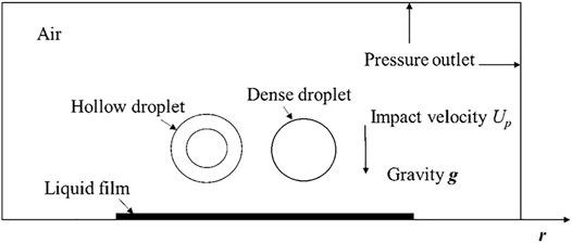
Figure 1 shows the geometric model of a hollow droplet and a dense droplet impinging on a liquid film. The two droplets share the same impacting velocity Up. The initial diameter of the droplets D0 is 2.091 mm with a dimensionless shell thickness
Representative evolution stages prior to and after the droplets' impingement are presented in Figures 2A–C. The spreading diameters of the hollow and continuous dense droplets are Dp,s and D0,s, respectively. The height of the central jet between the droplets is hc, and the heights of the edge jet of the hollow droplet and continuous dense droplet are hp,j and h0,j, respectively. The height of the counter jet inside the hollow droplet is Lj. For convenience and being consistent with previous works, the spreading factor of a hollow droplet, the spreading factor of a dense droplet, the edge jet height of the hollow droplet, the edge jet height of the dense droplet, and the counter jet height were normalized based on the droplet diameters for analysis, i.e., fp = Dp,s/Dp, f0 = D0,s/D0,
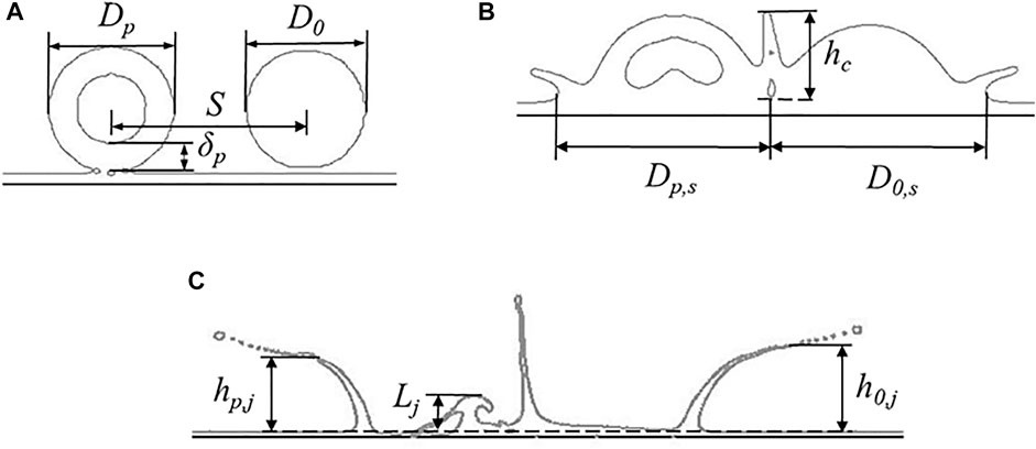
FIGURE 2. Typical evolution stages in the impact of hollow droplet and continuous dense droplet on the liquid film: (A) droplets contact with liquid film, (B) central jet between droplets, and (C) counter jet inside the hollow droplet.
Numerical Method and Mode
In this study, the CLSVOF method (Sussman and Puckett, 2000) is employed to perform the simulations with the aid of the commercial software FLUENT. Continuity, momentum, and energy equations used throughout the domain include
where
where
where subscripts g and l represent gas and liquid phases, respectively.
Notice that the numerical method above is only briefly introduced, and more details about this method, in particular the solving schemes for the numerical method, can be found in the authors’ previous studies (Li et al., 2018; Li et al., 2019).
In this work, a two-dimensional model that is shown in Figure 1 is used, with a computational domain of 15 × 30 mm. For the purpose of accurately capturing the complex evolution of the central jet between droplets and the counter jet inside droplets, intensified adaptive meshes are used. Numerical results from the structured meshes with total grid numbers of 150,000, 186,000, and 252,000 are compared to check mesh independence. The numerical conditions include Dp = 2.091 mm,
Model Validation
For the model validation, it will be a good choice to compare the numerical results with closely related experiments. Unfortunately, the experiments of a hollow droplet and a continuous dense droplet simultaneously impacting on a liquid film are not available at present. To warrant the effectiveness of the model, the cases of a hollow droplet impact, and a continuous dense droplet impact are validated, respectively. For the hollow droplet, only experimental results of the hollow droplet impact on a dry substrate are available (Gulyaev and Solonenko, 2013). The conditions are expressed as follows: a glycerin hollow droplet with an initial diameter Dp = 5.25 mm and dimensionless shell thickness
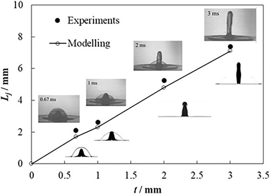
FIGURE 3. Comparison of the experiment (Gulyaev and Solonenko, 2013) and simulation results for hollow droplet impact.
For the dense droplet, experimental observation and measurement from a previous study (Li et al., 2017) are used to validate the numerical result of a continuous dense droplet impact on a liquid film. The conditions are expressed as follows: a continuous dense droplet with an initial diameter D0 = 2.378 mm at 2.1 m s−1 velocity vertically impacting on a liquid film with an initial thickness of 0.2 mm. The droplet temperature is the same as ambient air. The comparison is exhibited in Figure 4, which shows a very good agreement in droplet qualitative evolution and quantitative spreading factor.
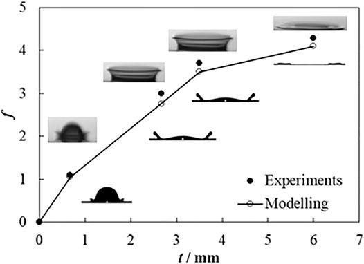
FIGURE 4. Comparison of the experiment (Li et al., 2017) and simulation results for the continuous dense droplet.
Results and Discussions
Morphology of Impacting Droplets
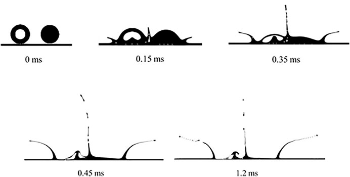
Figure 5 shows the interface evolution of a hollow droplet and a dense droplet simultaneously impacting on a liquid film, with the impact velocity of 6 m s−1. The time when the droplets make contact with the liquid film is set as 0 ms.
As can be observed in Figure 5, the droplets spread after making contact with the liquid film. At 0.15 ms, the hollow droplet and continuous dense droplet collide, where the central jet can be found at the colliding point. Also, an entrapped air bubble emerges inside the central jet. At the outside spreading edge, a liquid sheet resulting from the effects of spreading potential, viscous dissipation, and surface tension is observed. At 0.35 ms, the central jet presents an oblique movement toward the hollow droplet. This is mainly due to the effect of the larger spreading potential of the continuous dense droplet, which produces larger colliding energy upon droplets' collision, causing an oblique central jet. Liquid at the top of the central jet ruptures, which produces secondary tiny droplets. Concomitantly, the fluid inside the hollow droplet converges at the impact center, where the counter jet is enveloped. At 0.45 ms, for the hollow droplet impact, the counter jet moves across the liquid shell, resulting in the rupture of the liquid shell. For the continuous dense droplet impact, fluid inside the liquid sheet deforms greatly as a groove, without the counter jet that appears inside the hollow droplet. It is also found that the liquid at the rim of the edge liquid sheet for continuous dense droplet breaks into secondary droplets, which cannot be found for the edge liquid sheet from the hollow droplet. At 1.2 ms, the liquid at the edge liquid sheet shows a more obvious splashing process for both the hollow droplet and the continuous dense droplet. Thus, the obliquely moving central jet and the counter jet are the unique features for the simultaneous impingement of a hollow droplet and a continuous dense droplet.
Fluid Dynamics Analysis
Figure 6 shows pressure and velocity distributions during a hollow droplet and a continuous dense droplet impacting on a liquid film simultaneously, where the conditions are the same to those shown in Figure 5.
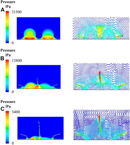
FIGURE 6. Pressure and velocity distribution of droplets impact at different time instants: (A) 0.05 ms, (B) 0.2 ms, and (C) 0.5 ms.
As can be found in Figure 6A, at 0.05 ms, when the droplets make contact with the liquid film, pressures at the spreading edge for both the hollow droplet (31,453 Pa) and continuous dense droplet (29,864 Pa) are greater than the main part of the droplets, which causes the spreading of the droplets. The spreading velocities for the hollow droplet and continuous dense droplet are 13.9 and 14.769 m s−1, respectively.
In Figure 6B at 0.2 ms, the maximum pressure is at the bottom of the central droplets (20,834 Pa). A large pressure gradient can be found within the central jet, which is the main cause for the formation of the central jet. Besides, pressures at the root of the edge liquid sheet for the hollow droplet and the continuous dense droplet are 7,877 and 8,957 Pa, respectively, which are the maximum in the edge liquid sheet area. The pressure gradient causes the formation of an edge jet. Also, the pressure gradient inside the counter jet within a hollow droplet decreases from the bottom (10,264 Pa) to the top (8,839 Pa), which is the main cause for the formation of the counter jet. As can been observed in the velocity distribution, the maximum velocity (14.48 m s−1) of the central jet is at the top, which is larger than the spreading velocities of the hollow droplet (5 m s−1) and continuous dense droplet (5.36 m s−1), as well as the edge jet velocities of the hollow droplet (10 m s−1) and continuous dense droplet (11.43 m s−1). The maximum velocity at the top of the counter jet inside the hollow droplet is 1.525 m s−1.
It can be seen from Figure 6C that at 0.5 ms, the pressure at the bottom of the central jet reduces to 2,173 Pa. The pressure gradient inside the central jet is not sufficient to sustain the development of the central jet. A breakup can be seen at the top of the central liquid jet, where the secondary droplets show significant kinetic splashing under fluid instabilities. Also, the pressures at the spreading edge (2,874 Pa) and the root of the edge jet (1,823 Pa) are larger than those of their surrounding areas, which means that the pressure gradient keeps resulting in spreading and edge jetting. The pressure gradient inside the counter jet within the hollow droplet is also large enough to keep forming the counter jet. As can be found in the velocity distribution at the same instant, the velocity at the top of the central jet reduces to 5.21 m s−1, while the velocity of the secondary droplets is 14.8 m s−1. Also, the spreading velocities of the hollow droplet and continuous dense droplet reduce to 4.5 and 5.2 m s−1, respectively, but the edge jet velocities of the hollow droplet and continuous dense droplet increase to 9.7 and 10.4 m s−1, respectively. The velocities at the bottom of the central jet and counter jet are 0.7 and 0.7439 m s−1, respectively, with an almost existing flow stagnation near this point. Note that it is more difficult to transfer the heat from the droplets to wall surface because of such an existence of flow stagnation.
Effects of Impact Velocity on Flow Characteristics
Figure 7 shows the spreading factor f of two droplets impacting on a liquid film, where S = 3.2 mm and Up = 6 and 10 m s−1. The spreading factors for the different droplets increase with time. Droplets with a higher impact velocity have larger spreading factors. The maximum spreading factors for the hollow droplet at 6 and 10 m s−1 are 3.17 and 3.7, respectively, while the maximum spreading factors for a continuous dense droplet at 6 and 10 m s−1 are 3.37 and 4.0, respectively. The spreading factor of a continuous dense droplet is always larger than that of a hollow droplet at different impact velocities.
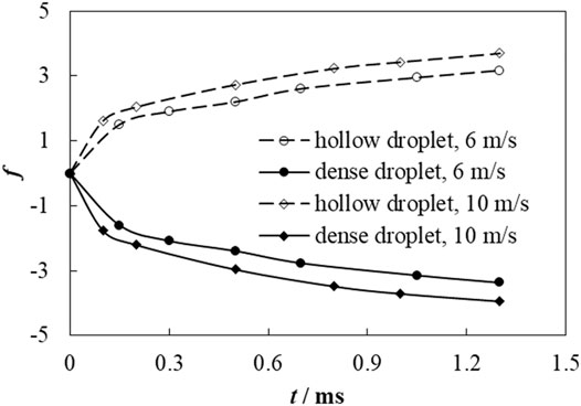
FIGURE 7. Spreading factor of a hollow droplet and continuous dense droplet at impact velocities of 6 and 10 m s−1.
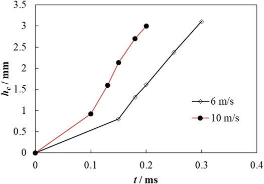
Figure 8 shows the height of the central jet for droplets' impaction at different time instants and impact velocities. Droplets with different impact velocities have the same trend for the height of the central jet. At the initial stage of impact, the height of the central jet increases gently, while after t = 0.1 and 0.15 ms, the increasing trend is accelerated. Also, as can be seen in Figure 6B, an upward-moving flow is observed at the colliding point between the droplets caused by a high pressure at that point, which forms the central jet between the droplets. Due to this, the droplets with a higher impact velocity have greater spreading kinetic energy, which can be converted to a larger pressure at the colliding point between the droplets; consequently, a greater jetting potential can be formed in droplets' colliding. Therefore, the droplets with a higher impact velocity have a larger central jet height.
Figure 9 shows the dimensionless height of the counter jet inside a hollow droplet during droplets' impaction at the different velocities, where t*= tUp/Dp. As can be seen in Figure 9, the dimensionless height of the counter jet is close to each other at different velocities at the initial stages of its formation. When t* = 0.5,
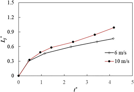
FIGURE 9. Dimensionless counter jet height of hollow droplet at impact velocities of 6 and 10 m s−1.
Figure 10 exhibits the dimensionless height of the edge jet during the droplets' impact on the liquid film at different impact velocities. It is found that the droplets with higher impact velocity have larger dimensionless heights of the edge jet. The dimensionless height of the edge jet for a continuous dense droplet is slightly larger than that for a hollow droplet. This means that the edge jet for a continuous dense droplet is easier to break up due to the effect of hydrodynamic instabilities, which is corresponding to the morphology of droplet impact shown in Figure 5.
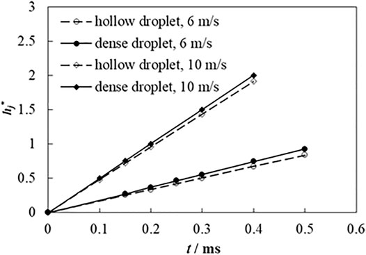
FIGURE 10. Dimensionless edge jet height of hollow droplet and continuous dense droplet at impact velocities of 6 and 10 m s−1.
Effects of Impact Velocity on Heat Transfer Characteristics
Figure 11 shows the distribution of wall heat flux (qw) when a hollow droplet and a continuous dense droplet impinge on a liquid film at several time instants under the impact velocities of 6 and 10 m s−1, in which S = 3.2 mm. The wall heat flux qw can be expressed as
where hf is fluid-side local heat transfer coefficient, determined by
where
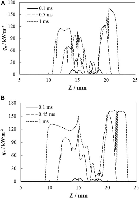
FIGURE 11. Wall heat flux distribution at impact velocities of 6 and 10 m s−1: (A) 6 m s−1 and (B) 10 m s−1.
In Figure 11A at 0.1 ms, the wall heat flux is relatively low because the liquid film prohibits the thermal effect of the impacting droplets on the wall surface. As droplets spread, the interaction between the droplets and wall is enhanced remarkably. At 0.5 ms, the wall heat flux increases sharply, and the maximum wall heat flux reaches 126 kW m−2. Due to the vortex flow near the wall surface, wall heat flux fluctuates at the droplets' impacting the area. When t = 1 ms, the maximum wall heat flux increases to 165.2 kW m−2. It needs to be pointed that the wall heat flux at the hollow droplet–impacting area is larger than at the continuous dense droplet–impacting area. This is because the hollow droplet disturbance is more violent than the continuous dense droplets' due to the formation of a counter jet inside the hollow droplet. Also, it can be found that the thermally affected distances of the hollow droplet (rh,p) are 4.8 and 6 mm at t = 0.5 and 1 ms, respectively, while the thermally affected distances of the continuous dense droplet (rh,0) are 4.9 and 6.196 mm at t = 0.5 and 1 ms, respectively; the latter of these being slightly larger than those for the hollow droplet. It can be concluded that the dynamics of the impacting droplets affects heat transfer during impaction significantly. It is also found that at instants of 0.5 and 1 ms, when R = 16.5 and 17 mm, respectively, the wall heat flux almost decreases to zero. This is because of flow stagnation (as shown in Figure 6C) at this point due to the formation of the central jet that greatly inhibits heat transfer. This phenomenon should be considered and addressed in particular droplet spray applications.
In Figure 11B, when the impact velocity increases to 10 m s−1, the wall heat flux distribution has almost the same trend as that of impacting at 6 m s−1. At 0.45 ms, the maximum wall heat flux reaches 160.4 kW m−2, which is very close to that at t = 1 ms for an impact velocity of 6 m s−1. The thermally affected region of the continuous dense droplet is also larger than that of the hollow droplet at 0.45 and 1 ms, where rh,0 = 5.6452 and 7.6452 mm, and rh,p = 5.512 and 7.315 mm, respectively. It can also be found that rh,0 and rh,p of the droplets impacting at 10 m s−1 are larger than those impacting at 6 m s−1. This means that increasing the impact velocity can enhance heat transfer when the droplets impinge on a liquid film due to the intensified interaction between the droplets and wall surface at higher impact velocities.
Conclusion
With the aid of the CLSVOF method, a hollow droplet and a continuous dense droplet simultaneously impacting on a liquid film are numerically studied in this research. Spreading, central jet between droplets, and edge liquid sheet can be observed after droplets' impingement. Counter jet can be found inside a hollow droplet after impact, which is the main differential feature when compared with a continuous dense droplet. A pressure gradient is the main cause for spreading, central jet, edge liquid sheet, and counter jet formation. The impact velocity is closely related to the dynamics and heat transfer for droplets' impacting on liquid film. Droplets with a higher velocity have a larger spreading factor, central jet height, edge jet height, and counter jet height. The spreading factor and edge jet height for continuous dense droplets are larger than those for hollow droplets. Wall heat flux increases more notably for droplets with a higher impact velocity. A hollow droplet has a larger wall heat flux but a smaller thermally affected region than a continuous droplet. This study could provide guidelines for chip-level electronics cooling, internal combustion design, and surface coating.
Data Availability Statement
The original contributions presented in the study are included in the article/Supplementary Material, further inquiries can be directed to the corresponding author.
Author Contributions
GL and DH contributed to the conception and design of the study, and DL performed the simulations and wrote the first draft of the manuscript. All authors contributed to manuscript revision, and read and approved the submitted version.
Funding
Support of the National Natural Science Foundation of China under Grant No. 51876025 and NSAF Joint Fund under U2030112 is gratefully acknowledged.
Conflict of Interest
The author DL is employed by CNOOC Research Institute Co. Ltd.
The remaining authors declare that the research was conducted in the absence of any commercial or financial relationships that could be construed as a potential conflict of interest.
Publisher’s Note
All claims expressed in this article are solely those of the authors and do not necessarily represent those of their affiliated organizations, or those of the publisher, the editors, and the reviewers. Any product that may be evaluated in this article, or claim that may be made by its manufacturer, is not guaranteed or endorsed by the publisher.
References
Alghoul, S. K., Eastwick, C. N., and Hann, D. B. (2011). Normal Droplet Impact on Horizontal Moving Films: an Investigation of Impact Behaviour and Regimes. Exp. Fluids 50 (5), 1305–1316. doi:10.1007/s00348-010-0991-0
Brackbill, J. U., Kothe, D. B., and Zemach, C. (1992). A Continuum Method for Modeling Surface Tension. J. Comput. Phys. 100 (2), 335–354. doi:10.1016/0021-9991(92)90240-y
Chen, Y., and Deng, Z. (2017). Hydrodynamics of a Droplet Passing through a Microfluidic T-junction. J. Fluid Mech. 819, 401–434. doi:10.1017/jfm.2017.181
Chen, Y., Liu, X., and Shi, M. (2013). Hydrodynamics of Double Emulsion Droplet in Shear Flow. Appl. Phys. Lett. 102 (5), 051609. doi:10.1063/1.4789865
Chen, Y., Wu, L., and Zhang, L. (2015). Dynamic Behaviors of Double Emulsion Formation in a Flow-Focusing Device. Int. J. Heat Mass Transfer 82, 42–50. doi:10.1016/j.ijheatmasstransfer.2014.11.027
Cossali, G., Marengo, M., and Santini, M. (2004). “Impact of Single and Multiple Drop Array on a Liquid Film,” in 19th Annual Meeting of ILASS (Nottingham, UK: ILASS Europe), 1–8. 06-08/09/2004.
Gulyaev, I. P., Solonenko, O. P., Gulyaev, P. Y., and Smirnov, A. V. (2009). Hydrodynamic Features of the Impact of a Hollow Spherical Drop on a Flat Surface. Tech. Phys. Lett. 35 (10), 885–888. doi:10.1134/S1063785009100034
Gulyaev, I. P., and Solonenko, O. P. (2013). Hollow Droplets Impacting onto a Solid Surface. Experiments in Fluids 54 (1), 1432. doi:10.1007/s00348-012-1432-z
Guo Jia-Hong, J. H., Dai Shi-Qiang, S. Q., and Dai Qin, Q. (2010). Experimental Research on the Droplet Impacting on the Liquid Film. Acta Phys. Sin. 59 (4), 2601–2609. doi:10.7498/aps.59.2601
Harlow, F. H., and Welch, J. E. (1965). Numerical Calculation of Time-dependent Viscous Incompressible Flow of Fluid with Free Surface. Phys. Fluids 8 (12), 2182–2189. doi:10.1063/1.1761178
Kumar, A., Gu, S., and Kamnis, S. (2012). Simulation of Impact of a Hollow Droplet on a Flat Surface. Appl. Phys. A. 109 (1), 101–109. doi:10.1007/s00339-012-7043-y
Kumar, A., Gu, S., Tabbara, H., and Kamnis, S. (2013). Study of Impingement of Hollow ZrO2 Droplets onto a Substrate. Surf. Coat. Technology 220, 164–169. doi:10.1016/j.surfcoat.2012.08.061
Lee, S. H., Hur, N., and Kang, S. (2011). A Numerical Analysis of Drop Impact on Liquid Film by Using a Level Set Method. J. Mech. Sci. Technol. 25 (10), 2567–2572. doi:10.1007/s12206-011-0613-7
Lee, T., and Liu, L. (2010). Lattice Boltzmann Simulations of Micron-Scale Drop Impact on Dry Surfaces. J. Comput. Phys. 229 (20), 8045–8063. doi:10.1016/j.jcp.2010.07.007
Li, D., and Duan, X. (2019). Numerical Analysis of Droplet Impact and Heat Transfer on an Inclined Wet Surface. Int. J. Heat Mass Transfer 128, 459–468. doi:10.1016/j.ijheatmasstransfer.2018.09.025
Li, D., Duan, X., Zheng, Z., and Liu, Y. (2018). Dynamics and Heat Transfer of a Hollow Droplet Impact on a Wetted Solid Surface. Int. J. Heat Mass Transfer 122, 1014–1023. doi:10.1016/j.ijheatmasstransfer.2018.02.017
Li, D. S., Qiu, X. Q., Zheng, Z. W., and Zhang, D. (2017a). Numerical Analysis of a Coupled Level Set-VOF Method for the Study of Droplet Impact on Wetted Surface. J. Chem. Eng. Chin. Universities 31 (3), 570–578.
Li, D., Zhang, D., and Zheng, Z. (2019). Numerical Analysis of Hollow Droplet Impacts on a Dry Flat Surface. Int. J. Heat Mass Transfer 129, 753–763. doi:10.1016/j.ijheatmasstransfer.2018.09.063
Li, D., Zhang, D., Zheng, Z., and Tian, X. (2017b). Numerical Analysis on Air Entrapment during a Droplet Impacts on a Dry Flat Surface. Int. J. Heat Mass Transfer 115, 186–193. doi:10.1016/j.ijheatmasstransfer.2017.08.023
Liang, G., Guo, Y., and Shen, S. (2014). Gas Properties on Crown Behavior and Drop Coalescence. Numer. Heat Transfer, B: Fundamentals 65 (6), 537–553. doi:10.1080/10407790.2014.884834
Liang, G., and Mudawar, I. (2017c). Review of Drop Impact on Heated walls. Int. J. Heat Mass Transfer 106, 103–126. doi:10.1016/j.ijheatmasstransfer.2016.10.031
Liang, G., and Mudawar, I. (2016). Review of Mass and Momentum Interactions during Drop Impact on a Liquid Film. Int. J. Heat Mass Transfer 101, 577–599. doi:10.1016/j.ijheatmasstransfer.2016.05.062
Liang, G., and Mudawar, I. (2017a). Review of spray Cooling - Part 1: Single-phase and Nucleate Boiling Regimes, and Critical Heat Flux. Int. J. Heat Mass Transfer 115, 1174–1205. doi:10.1016/j.ijheatmasstransfer.2017.06.029
Liang, G., and Mudawar, I. (2017b). Review of spray Cooling - Part 2: High Temperature Boiling Regimes and Quenching Applications. Int. J. Heat Mass Transfer 115, 1206–1222. doi:10.1016/j.ijheatmasstransfer.2017.06.022
Liang, G., Zhang, T., Chen, H., Yu, H., and Shen, S. (2019). Successive Impact of Multiple Droplets on Liquid Film. Eur. J. Mech. - B/Fluids 74, 389–398. doi:10.1016/j.euromechflu.2018.09.011
Liang, G., Zhang, T., Yu, H., Chen, H., and Shen, S. (2018). Simultaneous Impact of Multiple Droplets on Liquid Film. J. Ind. Eng. Chem. 65, 51–61. doi:10.1016/j.jiec.2018.04.011
Liu, X., Chen, Y., and Shi, M. (2013). Dynamic Performance Analysis on Start-Up of Closed-Loop Pulsating Heat Pipes (CLPHPs). Int. J. Therm. Sci. 65, 224–233. doi:10.1016/j.ijthermalsci.2012.10.012
Liu, X., Zhang, C., Yu, W., Deng, Z., and Chen, Y. (2016). Bubble Breakup in a Microfluidic T-junction. Sci. Bull. 61 (10), 811–824. doi:10.1007/s11434-016-1067-1
Lü, M., Ning, Z., Yan, K., Fu, J., and Sun, C. (2015). Instability and Breakup of Cavitation Bubbles within Diesel Drops. Chin. J. Chem. Eng. 23 (1), 262–267. doi:10.1016/j.cjche.2014.10.009
Negeed, E.-S. R., Albeirutty, M., and Takata, Y. (2014). Dynamic Behavior of Micrometric Single Water Droplets Impacting onto Heated Surfaces with TiO2 Hydrophilic Coating. Int. J. Therm. Sci. 79, 1–17. doi:10.1016/j.ijthermalsci.2013.12.011
Negeed, E.-S. R., Hidaka, S., Kohno, M., and Takata, Y. (2013). High Speed Camera Investigation of the Impingement of Single Water Droplets on Oxidized High Temperature Surfaces. Int. J. Therm. Sci. 63, 1–14. doi:10.1016/j.ijthermalsci.2012.07.014
Oguz, H. N., and Prosperetti, A. (1989). Surface-tension Effects in the Contact of Liquid Surfaces. J. Fluid Mech. 203, 149–171. doi:10.1017/s0022112089001412
Park, J. Y., Min, C. K., Granick, S., and Cahill, D. G. (2012). Residence Time and Heat Transfer when Water Droplets Hit a Scalding Surface. J. Heat Transfer-Transactions Asme 134 (10), 101503. doi:10.1115/1.4006802
Peck, B., and Sigurdson, L. (1994). The Three‐dimensional Vortex Structure of an Impacting Water Drop. Phys. Fluids 6 (2), 564–576. doi:10.1063/1.868352
Pravinraj, T., and Patrikar, R. (2017). Modelling and Investigation of Partial Wetting Surfaces for Drop Dynamics Using Lattice Boltzmann Method. Appl. Surf. Sci. 409, 214–222. doi:10.1016/j.apsusc.2017.02.242
Qiu, L., Dubey, S., Choo, F. H., and Duan, F. (2017). The Statistical Analysis of Droplet Train Splashing after Impinging on a Superheated Surface. J. Heat Transfer-Transactions Asme 139 (5), 052201. doi:10.1115/1.4035661
Raman, K. A., Jaiman, R. K., Lee, T. S., and Low, H. T. (2015). On the Dynamics of crown Structure in Simultaneous Two Droplets Impact onto Stationary and Moving Liquid Film. Comput. Fluids 107, 285–300. doi:10.1016/j.compfluid.2014.11.007
Rocco, G., Coppola, G., and De Luca, L. (2010). Simulation of Drop Impact on a Thin Liquid Film by Means of the VOF Method. Aerotecnica 89 (1), 25–35.
Roisman, I. V., and Tropea, C. (2002). Impact of a Drop onto a Wetted wall: Description of crown Formation and Propagation. J. Fluid Mech. 472, 373–397. doi:10.1017/S0022112002002434
Sivakumar, D., and Tropea, C. (2002). Splashing Impact of a spray onto a Liquid Film. Phys. Fluids 14 (12), L85–L88. doi:10.1063/1.1521418
Soriano, G. E., Zhang, T., and Alvarado, J. L. (2014). Study of the Effects of Single and Multiple Periodic Droplet Impingements on Liquid Film Heat Transfer. Int. J. Heat Mass Transfer 77, 449–463. doi:10.1016/j.ijheatmasstransfer.2014.04.075
Stevens, C. S. (2014). Scaling of the Splash Threshold for Low-Viscosity Fluids. Epl 106 (2), 24001. doi:10.1209/0295-5075/106/24001
Sussman, M., and Puckett, E. G. (2000). A Coupled Level Set and Volume-Of-Fluid Method for Computing 3D and Axisymmetric Incompressible Two-phase Flows. J. Comput. Phys. 162 (2), 301–337. doi:10.1006/jcph.2000.6537
Wang, H., Zhao, Z., Liu, Y., Shao, C., Bian, F., and Zhao, Y. (2018a). Biomimetic Enzyme cascade Reaction System in Microfluidic Electrospray Microcapsules. Sci. Adv. 4 (6). doi:10.1126/sciadv.aat2816
Wang, J., Gao, W., Zhang, H., Zou, M., Chen, Y., and Zhao, Y. (2018b). Programmable Wettability on Photocontrolled Graphene Film. Sci. Adv. 4 (9), eaat7392. doi:10.1126/sciadv.aat7392
Wang, J., Sun, L., Zou, M., Gao, W., Liu, C., Shang, L., et al. (2017). Bioinspired Shape-Memory Graphene Film with Tunable Wettability. Sci. Adv. 3 (6), e1700004. doi:10.1126/sciadv.1700004
Yarin, A. L. (2006). DROP IMPACT DYNAMICS: Splashing, Spreading, Receding, Bouncing. Annu. Rev. Fluid Mech. 38, 159–192. doi:10.1146/annurev.fluid.38.050304.092144
Zhang, T., Muthusamy, J. P., Alvarado, J. L., Kanjirakat, A., and Sadr, R. (2016). Numerical and Experimental Investigations of crown Propagation Dynamics Induced by Droplet Train Impingement. Int. J. Heat Fluid Flow 57, 24–33. doi:10.1016/j.ijheatfluidflow.2015.10.003
Nomenclature
a Minimum size of computational cell
cp Specific heat
Dp Initial diameter of hollow droplet
Dp,s Spreading diameter of hollow droplet
D0 Initial diameter of continuous dense droplet
D0,s Spreading diameter of continuous dense droplet
f Spreading factor
h Heat transfer coefficient
hc Central jet height
hp,j Edge jet height of hollow droplet
h0,j Edge jet height of continuous dense droplet
H Heaviside function
L Radius coordinate
Lj Height of counter jet
p Pressure
qw Wall heat flux
rh,p Thermally affected distance of hollow droplet
rh,p Thermally affected distance of hollow droplet
S Droplets horizontal interval
t Time
Up Impact velocity
y Direction normal to wall
Greek symbols
δp Shell thickness
θ Equilibrium contact angle
κ (ϕ) Interface curvature
λ Thermal conductivity
μ Viscosity
ρ Density
σ Surface tension coefficient
ϕ Level set function
Superscript
∗ Dimensionless
Subscripts
g Gas phase
l Liquid phase.
Keywords: droplet impact, hollow droplet, continuous dense droplet, central jet, counter jet
Citation: Li D, Liang G and Hua D (2022) Simultaneous Impact of Hollow Droplet and Continuous Dense Droplet on Liquid Film. Front. Energy Res. 10:911458. doi: 10.3389/fenrg.2022.911458
Received: 02 April 2022; Accepted: 12 April 2022;
Published: 19 May 2022.
Edited by:
Chengbin Zhang, Southeast University, ChinaReviewed by:
Cheng Yu, University of Hawaii at Manoa, United StatesWei Gao, Harvard University, United States
Copyright © 2022 Li, Liang and Hua. This is an open-access article distributed under the terms of the Creative Commons Attribution License (CC BY). The use, distribution or reproduction in other forums is permitted, provided the original author(s) and the copyright owner(s) are credited and that the original publication in this journal is cited, in accordance with accepted academic practice. No use, distribution or reproduction is permitted which does not comply with these terms.
*Correspondence: Dan Hua, huadan@usts.edu.cn
 Dashu Li1
  Gangtao Liang
 Dan Hua