 André Tristany Farinha1*†
 Julien di Tria1†
 Marta Reyes2Constanca Rosas1Oscar Pang1
 Raphael Zufferey1,3
 Francesco Pomati2
 Mirko Kovac1,4*
- 1Aerial Robotics Laboratory, Department of Aeronautics, Imperial College London, London, United Kingdom
- 2Department of Aquatic Ecology, Eawag: Swiss Federal Institute of Aquatic Science and Technology, Dübendorf, Switzerland
- 3Biorobotics Laboratory, École Polytechnique Fédérale de Lausanne, Lausanne, Switzerland
- 4Materials and Technology Center of Robotics, Department of Functional Materials, Empa - Swiss Federal Laboratories for Materials Science and Technology, Dübendorf, Switzerland
Monitoring of aquatic habitats for water quality and biodiversity requires regular sampling, often in off-shore locations and underwater. Such sampling is commonly performed manually from research vessels, or if autonomous, is constrained to permanent installations. Consequentially, high frequency ecological monitoring, such as for harmful algal blooms, are limited to few sites and/or temporally infrequent. Here, we demonstrate the use of MEDUSA, an Unmanned Aerial-Aquatic Vehicle which is capable of performing underwater sampling and inspection at up to 10 m depth, and is composed of a multirotor platform, a tether management unit and a tethered micro Underwater Vehicle. The system is validated in the task of vertical profiling of Chlorophyll-a levels in freshwater systems by means of a custom solid sample filtering mechanism. This mechanism can collect up to two independent samples per mission by pumping water through a pair of glass-fibre GF/F filters. Chlorophyll levels measured from the solid deposits on the filters are consistent and on par with traditional sampling methods, highlighting the potential of using UAAVs to sample aquatic locations at high frequency and high spatial resolution.
1 Introduction
Aquatic ecosystems—both freshwater and marine—are fundamental to both Earth system dynamics and to human society Wang-Erlandsson et al. (2022). Water bodies provide the foundation for our life, health, and wealth, through “ecosytem services” such as nutrients’ cycling and primary production, climate regulation, clean water and fisheries, as well as tourism by means of aesthetics and recreational values of natural aquatic resources D’Alelio et al. (2021). Aquatic ecosystems are however very fragile and extensively perturbed by anthropogenic activities at local and global scales Wang-Erlandsson et al. (2022). Given the importance of aquatic resources for biodiversity, conservation and ecosystem services, there is a scientific interest and a societal need to monitor ecosystem state and water quality, ideally at low cost, high frequency and large spatial scales. Such needs imply the selection of relevant ecosystem variables to monitor, and of monitoring tools that minimize the imposed trade-offs between spatial and temporal resolution, and costs.
The estimation of abundance and diversity of phytoplankton in pelagic aquatic ecosystems is the most common, and often mandatory, biological parameter to monitor, to evaluate the quality of water bodies. Phytoplankton is a key component of all aquatic food-webs, encompassing a variety of photosynthetic organisms from eukaryotic microalgae to cyanobacteria. Having a short lifespans and being regulated by essential inorganic resources (including human pollutants), phytoplankton communities are sensitive to environmental conditions and represent effective indicators of environmental change, ecosystem health and water quality (Directives originating from the EU, 2000; Xu et al., 2001). One alarming response of phytoplankton to anthropogenic pollution, and a worldwide threat to aquatic ecosystem services, is the formation of blooms, i.e., mass accumulation of microalgae Isles and Pomati (2021). Phytoplankton blooms are increasing worldwide due to eutrophication and climate warming Huisman et al. (2018); Ho et al. (2019), with annual societal costs in the billions of Euros. In freshwaters, dense and often toxic blooms are associated with cyanobacteria Huisman et al. (2018). Forecasting or real time detection of algal blooms is a central concern in ecosystem management. The ability to promptly identify blooms would allow stakeholders to respond to human health or ecosystem service concerns. However, current early warning approaches suffer from severe drawbacks due to lack of spatial and temporal resolution in sampling and detection of these events.
Although automated instruments are available and used Lombard et al. (2019); Merz et al. (2021), phytoplankton monitoring is most commonly performed by dedicated personnel, making it difficult, time consuming and expensive Pomati et al. (2011). Dedicated laboratories perform sample collection, transport and storage for subsequent analysis by technicians and trained taxonomists, in case identification of microalgae is necessary. In many monitoring programs, particularly those concerning public health issues like harmful algal blooms, sampling should be rapid and target multiple locations and ideally multiple depths underwater, which is inconvenient and often difficult to achieve. Some locations, or deep chlorophyll-a (Chl-a) maxima which often characterise algal blooms, might not be easily accessible, limiting our ability to detect potential environmental threats. Aquatic ecosystem monitoring would hence tremendously benefit from autonomous sampling devices for phytoplankton monitoring, which allow multiple sample collection in offshore and/or inaccessible sites.
As summarised in Figure 1, the use of UAVs for water sampling shows potential for automating sampling and expanding the breadth of water research. In fact, the use of UAVs for this task is not a novel concept, having been employed by Ore et al. (2015) and Schwarzbach et al. (2014), and subsequently used in various different applications Lally et al. (2019). Amongst these, several are of particular interest. The sampling of a remote crater lake showcases UAV based water sampling as an adequate method for sampling in remote and hazardous regions Terada et al. (2018). The surface mapping of water quality using water samples and on-board sensors demonstrates the usage of UAVs for mapping of spatial gradients in bodies of water, Koparan et al. (2020). Finally, simultaneous sampling and sensor deployment showcases the potential of integrating these methods in real-time networks Ribeiro et al. (2016). Here, we would like to highlight two distinguishable methods used for water sample collection. The first relies on a pump to fill a container present on-board the UAV, while the second is much more widely used and relies on a cable suspended payload with a container that can be passively triggered by buoyancy Benson et al. (2019), by a microcontroller Koparan et al. (2020); Terada et al. (2018), or by a messenger probe Koparan et al. (2018). The latter is remarkably similar to standard depth water samplers and if employed for depth sampling, could constitute a simple alternative to the method here presented.
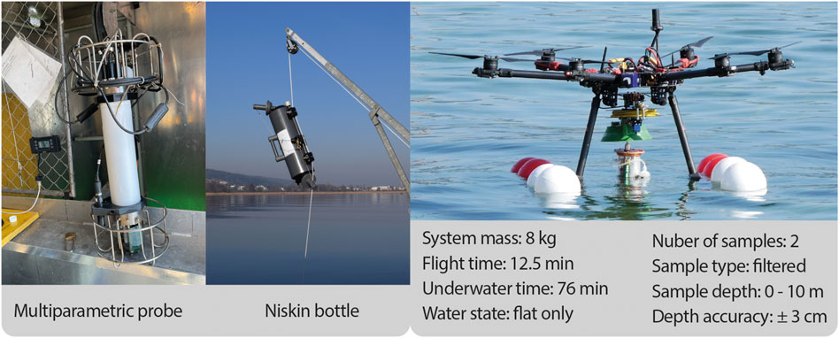
FIGURE 1. Sampling methods used in this publication. A multiparametric probe collects data autonomously along a vertical profile of the lake in a fixed location. A Niskin bottle is used off-board a motor-boat to collect water at depth for later filtration and analysis. The MEDUSA system developed for remote acquisition of water samples at depth.
Remote water sampling at depth with autonomous vehicles has been previously performed using non-flying Autonomous Underwater Vehicles (AUVs) Zhang et al. (2019), but these systems are normally bulky and heavy, hindering access to many research sites. Being inherently lightweight and facilitating access to remote locations through flight, UAV based methods can be of particular interest in many applications. Thus far, two UAV systems have used sensor probes lowered from UAVs Chung et al. (2015); Ore and Detweiler (2018) to measure thermophysical properties of water at depth. Concerning water sampling at depth, an author has done it successfully at up to 3 m depth using multiple cable suspended samplers actuated by a microcontroller Koparan et al. (2019). Also using a cable suspended sampler, another author has commercialised a method that has been successfully demonstrated up to an impressive depth of 92 m Castendyk et al. (2019).
In light of this recent work, we find there is a lack of fully integrated UAV solutions which perform targeted sampling at accurate depths, i.e., not relying on sampler depths set a priori to flight (Koparan et al. (2019)) or not requiring multiple flights and interfaces for a signle sample (Castendyk et al. (2019)). A new class of vehicles capable of seamless motion in water and air is, in our view, a necessity in this effort.
Unmanned Aerial-Aquatic Vehicles (UAAVs)1 are hybrid unmanned vehicles capable of traveling through air and water, normally fully integrated into a single package. These robots are capable of performing a new class of hybrid aerial-aquatic missions in challenging environments, creating opportunities for novel data-gathering strategies. This is achieved by providing in essence, means for researchers to access water-bodies from more convenient launch points, collect aerial data of said water-bodies, and perform direct measurements at the water surface or/and at depth at multiple locations. Literature in the UAAV field is extensive, Zeng et al. (2022), and varied mission profiles have been proposed thus far, Farinha et al. (2021). Amongst other achievements, UAAVs have been shown overcoming obstacles and escaping cluttered aquatic environments (Zufferey et al. (2019a); Siddall et al. (2017); Tétreault et al. (2020)), autonomously traveling underwater (Lyu et al. (2022)), and performing long duration sailing missions (Zufferey et al. (2019b)). These technologies are expected to extend hybrid sensing mission capabilities in aquatic environments by performing both remote observation and direct sampling. The direct sampling component can be valuable as a ground-truth mechanism in remote observation missions, but even more so in disciplines that require knowledge of water properties at depth, where sampling is more labour intensive.
Aerial-aquatic locomotion within a single vehicle often comes at the cost of compromising performance and limiting operational envelope. We previously investigated separating the aquatic and aerial components into two agents, taking advantage of the robustness of standard multicopter configurations and the simplicity of modular systems, Debruyn et al. (2020). This solution (the MEDUSA system - Multi-Environment Dual-robot for Underwater Sample Acquisition) proved to be simple and reliable, as well as easily expandable for different sensing and locomotion requirements. In this paper we demonstrate the application of the MEDUSA concept on the task of freshwater monitoring. The primary developments and contributions are the following: 1) Development of an autonomous filtration depth sampling system for use with an UAV; 2) Extension of the previous prototype’s operational envelope by redesigning the micro Underwater Vehicle (μUV) and its buoyancy control subsystem for operations at depth; 3) Redesign of the communication between the different agents into a more streamlined and robust package; 4) Field demonstration of vertical profiling of aquatic environments and Chlorophyll-a monitoring with MEDUSA.
2 Materials and methods
2.1 System operational envelope
By having the capacity to operate in air and in water at depth, MEDUSA type systems are especially indicated for sample collection and underwater inspection. The system here described is capable of collecting up to two independent water samples, speeding up the characterisation of gradients, and enabling a variety of hybrid aerial-aquatic missions as shown in Figure 2. This system can vertically take-off and land on solid ground or the water surface, and collect up to two water samples. These samples can be collected from a single location at different depths (S1, S2A), or from two different locations (S1, S2B). This provides flexibility in the characterisation of water bodies in their depth and span.
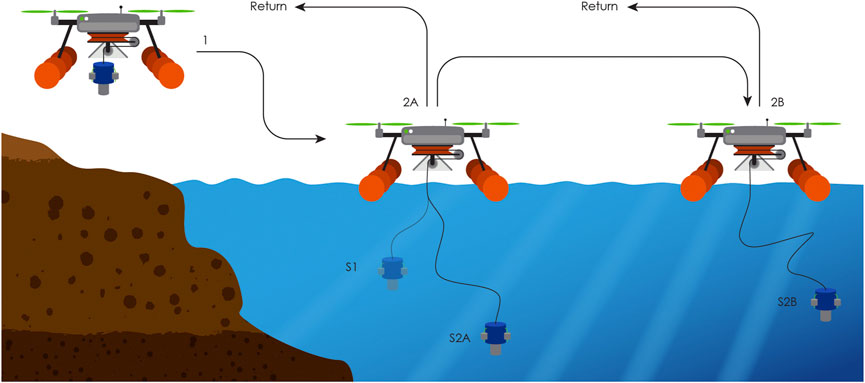
FIGURE 2. Mission profile for the MEDUSA system. Take-off from shore - 1 fly to aquatic location of interest - 2A land on the water surface - S1 collect first water sample at desired depth - S2A collect second water sample at different depth (OR) 2B fly to second location of interest and collect second sample S2B- return to shore.
The underwater operational envelope is restricted by the length of the tether to a half sphere of 10 m radius. Consequentially, the sampling depth is also restricted to a maximum depth of 10 m, which is generally sufficient to cover the entirety of the epilimnion layer of stratified lakes, where most of the phytoplankton production occurs.
2.2 System design
The MEDUSA system is composed of a standard multicopter platform, a water-landing system, a tether management unit and a micro underwater vehicle, with masses discretised in Table 1.
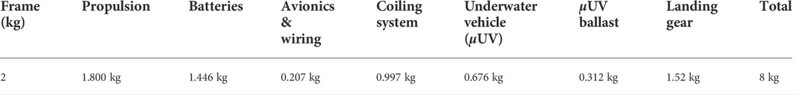
TABLE 1. Masses of principal components in the MEDUSA system.
Details on this implementation of MEDUSA are shown in Figure 3. The flying component is based on the Tarot X6 hexacopter frame with the DJI E1200 Standard propulsion system and 6.6 Ah of installed battery capacity. We use a Pixhawk four flight controller and the H-RTK F9P RTK GNSS system for position control. Communication is done via 900 MHz for long range radio-control and Mavlink stream for the ground-station, while analog video-feed is provided over 2.4 GHz.
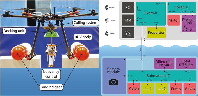
FIGURE 3. Principal mechanical subsystems that compose the MEDUSA system (left). On the left, electronics framework including: controllers, sensors, actuators and communication protocols for both the aerial (top) and underwater system (bottom).
The water landing gear is composed of eight spherical floats, which are chosen for its low weight (each weighs 120 g), buoyancy (each supports 1.2 kg) and high-visibility (in red and white). The floats are mounted in such a way that it creates a wide and stable floating platform on the water for the UAV. The heavier system components e.g., coiling system and μUV are located in the centre of the floating platform to maintain stability while the UAV is floating on water.
The coiling unit holds 11 m of Ethernet cable. Among the eight color wires in the cable, power and ground take two lines each, serial communication two more, analog video takes another and one is left free. The tension for power transmission is boosted to 30V, which keeps the voltage drop in the line bellow 4.4%, reducing power loss. Waterproofing at the μUV interface is ensured by using a waterproof cable gland connector, which also facilitates disassembly. The tether feeding is done by a high-torque continuous-rotation servo motor and managed by an Arduino-nano using PWM signal. Given we’re using a “dumb-servo”, the docking unit is fitted with contact switches to detect the terminus of recoil, while depth measured by the μUV provides information on the length of deployed cable. The docking unit is further fitted with a sonar range-finder to detect the approach of the μUV and slow down before docking contact.
The μUV is shaped as a cylindrical container, composed of a transparent polycarbonate tube capped on both ends by machined Aluminium 6,068 lids. One end can be opened and holds the tether connector while the other end holds a custom PCB. The PCB includes power modules, actuator drivers, sensors and an Arduino-nano micro-controller. Buoyancy control is achieved using a linear actuator connected to a piston, and a total pressure sensor provides feedback for the control loop. An FPV-flight analog camera placed in the μUV provides visual feedback via the video transmitter on-board the multicopter. It is worth noting that a major design challenge of a micro Underwater Vehicle (μUV) with appropriate mass for flight, is its compactness. This is made obvious by the mass of ballast used (30% of the μUV mass), to raise the system’s mass to a neutral buoyancy point. For this reason, the μUV needs to be designed for minimum volume, not mass.
2.2.1 Sampling system design
The design of a water sampling system to be integrated on an UAV comes with considerable technical challenges and design constraints. First, the UAV payload is limited and mission range is directly affected by an additional load. Secondly, the sample volume is dependant on the water properties of interest, varying the return payload depending on the application. Lastly, the UAV needs to be stable pre and post sample acquisition. A sampling solution that allows for flexibility in sampling volumes and negligible added payload in the form of water is filtration. Even though this method does not allow for some types of a posterirori analysis that require a liquid sample, thermophysical properties of water can still be measured in situ (albeit with lower precision), using on-board sensors. Nevertheless, filtration alone can provide relevant information such as concentration of suspended particles (e.g., algae, bacteria, zooplankton), their elemental composition (e.g., stoichiometry), and the biodiversity of the ecosystem based on environmental DNA Deiner et al. (2017). The sampling system demonstrated here is shown in Figure 4 and is capable of acquiring two independent samples per flight. This is achieved by using a pair of micro solenoid valves for flow diversion (or 2/3 solenoid valves), which open three parallel and independent lines. Two of these lines are used for sampling and have an inline filter holder for glass fibre filters (GF/F-filters). Further efforts are taken towards ensuring that no cross-contamination occurs, by dedicating the third line for purging before each sample; and by including a non-return valve at the end of each sampling line, thus avoiding the occurrence of reflux. Another feature of this design is scalability. Considering the 2/3 valve - filter holder - non-return valve as a single block, one can place as many of these as necessary in parallel to perform as many samples as required, adding only 40 g per additional line.
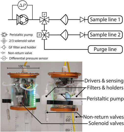
FIGURE 4. Filter based sampling system integrated in the μUV: hydraulic diagram (top), and physical components (bottom).
Filtration sampling methods rely on accurate knowledge of the volume of filtered water. The use of a peristaltic pump is thus clearly advantageous, due to its mostly linear characteristic (i.e., the pump’s rotation speed and flow rate remain constant with pressure loading). There is however a source of inaccuracy that should be accounted for, which is stall. In fact, peristaltic pumps have drastically reduced flow rates above certain pressure loading values, a condition that is reached as particles deposit on the filters and block the flow. The inclusion of a differential pressure sensor to measure the pressure loading on the pump allows a sample to be cut-off as soon as the pump starts operating outside its linear regime, thus leading to accurate and consistent sampling volume estimations.
2.2.2 Dual system communication setup
The integration of the system’s aerial and underwater components is done using customised open-source frameworks, i.e., PX4 (Meier et al. (2015)) for the flight control, Arduino for underwater control and sampling, and MAVLink (Koubâa et al. (2019)) for communication between the Ground Control Station (GCS), UAV and μUV. Control of the vehicle is done via the Radio Control (RC) and GCS which also receives feedback information; a complete list of control inputs and available feedback information is provided in Table 2.
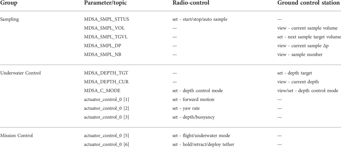
TABLE 2. List of parameters and topics used to handle the underwater locomotion mission section, sampling control, depth control and tether extension/retraction.
Figure 5A shows a visualisation of the two modes for the μUV’s depth control. A first mode uses the tether system to pull the μUV upwards, and the μUV’s weight with the piston fully retracted for downwards movement. A second mode uses a piston actuated by a linear actuator, which controls the μUV’s depth using a PID control loop and a total pressure sensor for feedback. Even though the second mode increases the system’s complexity and weight, it achieves tasks that would not be possible otherwise, such as underwater current compensation and depth control when moving in 3D space. For both cases, depth control is achieved using depth setpoints set via the MDSA_DEPTH_TGT parameter editable through the GCS, or via the RC using the pitch stick mapped to the actuator_control_0 topic.
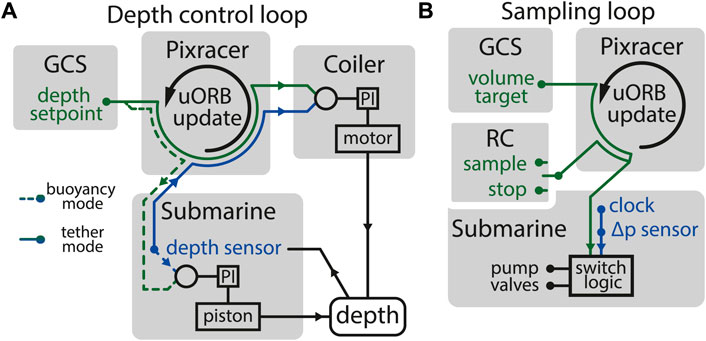
FIGURE 5. Distribution of actuators, sensors, control logic and user interfaces used across the MEDUSA system for: (A) μUV depth control and (B) sample collection logic.
As shown in Figure 5B, the timing, switching logic and actuation happens internally in the μUV, which uses the actuator_control_0 topic to trigger sample collection and manual stopping. The value of MDSA_SMPL_NB (Table 2) is incremented every time a sample is triggered and a switching logic chooses valve and pump actuation status that diverts the flow appropriately to either one of the samples or, when necessary, the purging line. In addition to the manual RC override, samples will automatically be stopped after a target volume set in the GCS is reached or the maximum Δp measured in-line is reached. The sample volume is calculated using a calibration curve that uses only the μC clock for the elapsed time.
2.3 Sampling procedures
In order to test and prove the functionality of the pump system on a real case scenario, a test was performed in Greifensee, Switzerland, with the aim of collecting a gradient of chlorophyll values water samples at different depths. Samples were collected from a boat by the monitoring station 47.36668 °N, 8.6651 °E (WGS 84). For this purpose glass microfiber filters, Grade GF/F (Whatman), 25 mm diameter and a pore size of 0.7 µm were used. To test the performance of the UAAV sampling system, manual samples were collected in parallel and manually filtered with syringes and filter holders as done in the UAVV system. Surface sample was taken directly from the boat by manually filling a syringe with surface water and measuring the volume of filtered water. Water samples at the different depths were collected with a niskin bottle, parallel to the UAAV system and the same filtering procedure was repeated. All filters were stored at 4°C and in the dark, and frozen (−20°C) once in the lab until sample processing.
2.3.1 On-site benchmarking
For the comparison of drone-sampled Chl-a with depth profiles, we used data from an Idronaut multiparametric probe and automated profiler (relevant information can be found in previous publications) Pomati et al. (2011); Merz et al. (2021). Water parameters monitored included pressure (i.e., depth), temperature, conductivity, oxygen, PAR (photosynthetic Active Radiation), turbidity, phycocyanin and chlorophyll-a, these last three using a Trilux fluorometer (https://chelsea.co.uk/).
2.3.2 Chlorophyll-a extraction
Chl-a extraction was done in the laboratory according to the standard procedure in Carranzo (2012). Using 90 percent ethanol, samples were vortexed, afterwards sonicated in an ice-waterbath for 15 min and stored at 4°C overnight. Extracted samples were filtered with 0.2 µm cellulose acetate syringe filters to remove particles and measured at 665 and 750 nm using a photospectrometer.
3 Results
Videos of the MEDUSA system in action during field trials and sampling tests can be found in Supplementary Video S1. Full system tests (flight - sample - sample - return) were performed in various locations in the United Kingdom, Switzerland and Croatia, in fresh and seawater. During these tests, samples were acquired at a maximum distance of 65 m from shore, and the maximum distance covered in flight was 600 m. The system achieved flight times of up to 13 min, however, we estimate the current setup can operate for 27 min if the maximum available battery payload is used. Flights were performed with winds up to 25 knots in a sheltered location where waves do not develop. While the wind was not a challenge for flight, it lead to rather fast drifting while MEDUSA floats on the water surface. This does not necessarily lead to failure, however, the μUV tends to get dragged behind it, which makes the depth control highly inaccurate. In terms of water surface state, all flights and landing attempts were performed on Douglas scale 0 to 1. One attempt was made for take-off in scale two conditions, however, a safe take-off was not possible. With increasing degrees of swell, it is not only take-off and landing that becomes challenging, but also deployment and recovery of the μUV can become impossible due to aggravated motion of the tether relatively to the coiling system. We’ve observed during sampling that the depth holding accuracy of the μUV is of ±3 cm, which outperforms other depth samplers we found in the literature. This estimate is however based on the on-board total pressure sensor, so it does not account for sensor bias that can occur due to local atmosphere or water density.
System tests where the acquired samples were analysed, were performed in three different locations in Switzerland: Zurich lake (47.319756, 8.553111) where there are no flight restrictions in place, Greifensee (47.366402, 8.665131) which a nature reserve with limited boat and flight activities allowed, and the EAWAG ponds facility (47.405155, 8.608538), where flight plans need to be approved by the flight authorities due to the proximity of the Dubendorf airbase. Taking into account these restrictions, full system tests were performed in Zurich lake, while in Greifensee the UAV was kept onboard a motorboat and the μUV lowered into the water using the depth control systems in place, and in the ponds facility the UAV was left to freely float in the ponds and the aquatic phase of the mission was carried out as in a full system trials.
3.1 Freshwater chlorophyll sampling
Samples were obtained in Greifensee from surface level to 9 m depth. The obtained Chlorophyll-a values are shown in Figure 6A alongside corresponding data from manual samples and from the Chl-a sensor values (from the multiparametric probe) logged at the time of sampling. It is shown that the UAAV and manual samples mostly match, with exception of the samples at 2 m depth. However, this mismatch is most likely a result of an error either with the manual sampling depth or with the sample tagging, as emphasised by the fact that the UAAV-based samples better follow the trend shown by the multi-parametric sensor values. It is also apparent that manual and UAAV samples show slightly lower Chl-a values than the sensor data. We expect, however, the latter ones to be less precise in absolute terms, as they are based on pigment fluorescence after light excitation, which can be influenced by a number of confounding factors, Falkowski and Kiefer (1985).
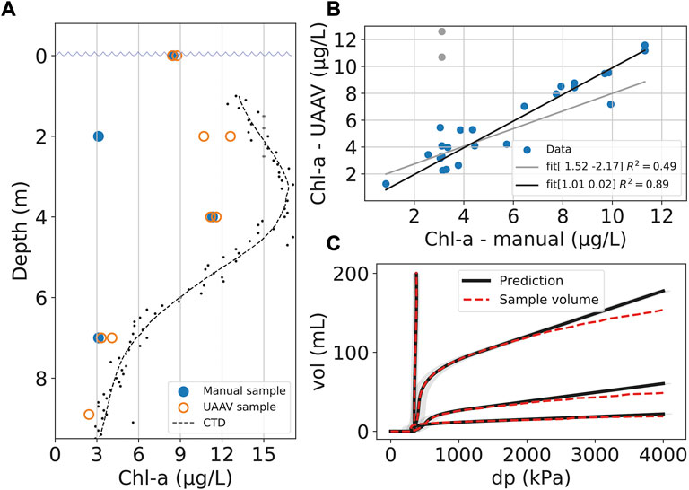
FIGURE 6. (A) Vertical section of the Chlorophyl-a values found at the Greifensee research station (47.366402, 8.665131) on the 30th of September 2021: manual sampling values obtained with a Niskin bottle, UAAV values obtained with MEDUSA and CTD values obtained using the automated multiparametric probe. (B) Correlation of UAAV - manual samples obtained in the same location/depth at several locations. In grey, the removed datapoints where a manual sampling error is likely to have occurred. (C) Evolution of filtered volume with differential pressure measued in the sampler, comparing volumes predicted using the linear model used in the sampler and the real measured volume. At 1,000 kPa, the limit for sample cut-off put in place to avoid non-linear effects.
In order to assess the contamination between sampler one and two in consecutive samples, pairs of consecutive S1 and S2 samples were ordered and a contamination hypothesis given by ChlM2 = (1 − ϵ) (ChlS2 + αChlS1) is tested for the ordered pairs as well as 1,000 random permutations of the same pairs. Where Mi and Si indexes correspond respectively to manual and UAV-sampler-i based samples of the same location and ϵ is the absolute error incurred by the measurement performed with sampler 1 before a measurement of a different location with sampler 2. As shown in Supplementary Figure S1, the confidence interval for the contamination ratio α is comparable to values encountered in other random permutations, which indicates contamination is likely not happening.
In order to validate the sampling system, samples taken using MEDUSA were taken in tandem with manual ones. The relation between the manual and UAAV based samples can be found in Figure 6B, where 27 valid sample pairs are discretized. Despite some variation in the 3–5 μg/L range, the data follows a close fit of a line of slope one intersecting at the origin, showcasing a one to one relation between the manual and UAAV-based methods. These results, however, show only that Chl-a values obtained using MEDUSA are comparable to manual methods. A full description of the method’s precision would require several more samples across the full range of Chl-a concentrations.
All UAAV-based samples were acquired with varying volumes, which were the result of the samples being cut-off when the Δp loading on the pump exceeded a threshold of 1,000 kPa. Figure 6C showcases 4 such samples where the system’s water outlet was collected onto a set of scales and the measured value compared to the prediction used by MEDUSA. Sample 1 corresponds to the filtering of clear water and thus the Δp remains constant and equivalent to the pressure loading of the valves, filter and tubing. In this situation, MEDUSA will cut-off the sample after reaching a predefined maximum volume, which is here set to 200 ml. Subsequent samples correspond to increasingly more turbid water. Thus, the sampled volume does not reach the set maximum volume, but the maximum Δp, after which the flow rate is no longer constant and the predicted sampled volume accumulates error.
4 Discussion
There are three main features that distinguish the method here described from the previous literature on UAV based depth water sampling (Ore and Detweiler (2018); Koparan et al. (2019); Castendyk et al. (2019)).
Firstly, as opposed to Ore and Detweiler (2018); Castendyk et al. (2019), the MEDUSA system lands on water to collect samples instead of hovering above it. This is done with the intention of saving energy while the samples are being collected, and thus increasing the system’s effective range. However, it also comes at an increased payload which has the opposite effect. Our experiments show that by flying without the water landing gear, MEDUSA can extend its flight time by
Secondly, the usage of a filtration system to collect samples. This system has the advantage of not changing the UAV’s dynamics after sample collection, however, the mass of the samples we collected thus far (20
Finally, the integration of underwater locomotion and flight in a single robot. Besides the obvious additional tasks that can be performed by the underwater robot, it allows us to accurately control the depth of the μUV. We have estimated the accuracy in depth control to be ±3 cm from the information of the depth sensor. However, no baseline measurement was used to confirm this value, and we do not claim to have a more accurate depth control than in Ore and Detweiler (2018). Another useful feature is the fact that we have access to real-time data about the samples, μUV depth and visual feedback, which allows for missions to be adjust in real-time. On the other hand, this level of integration creates the need for coiling heavy and stiff electrical cable which hinders operations. The impact of this is clearly seen as Castendyk et al. (2019) can achieve much greater depths than what would be feasible with such a cable. There is, however, room to improve the cable used by using higher performance tethers for underwater rovers, or even by providing the μUV with it is own power supply to reduce the number of lines necessary in the line. This, of course, comes with it is own challenges.
4.1 System design and field trials: Lessons learnt
Most UAAV systems we are aware of have operated at shallower depths than here described, which constituted a challenge in itself and lead to unexpected design choices. We summarise here some lessons learnt on the system design and trials, which we hope will prove useful in designing a similar system.
The design of the μUV is much more driven by volume limitations than weight. So, keeping all sealed components outside the chamber helped keep the volume low and consequentially reduce the payload in flight. Furthermore, the μUV is also much less subject to drag, as travel speeds are considerably low. It is thus not disadvantageous to design configurations with large cross-sections, if this results in simpler deployment and recovery by the UAV.
Opening and closing a sealed compartment in the field is troublesome, especially with live electronics in wet environments. We found that keeping the filter holders outside the μUV makes the process of recovering and replacing filters considerably safer and simpler.
A more effective coiling system than the one here described would use a stepper motor with encoder driving the winch with larger gear ratio through a timing belt. This results in a higher rotating torque setup with precise measurement of cable length, though, at the expense of weight and complexity.
The beyond visual-line-of-sight (BVLOS) requirement in remote water sampling mission imposes challenges in on-site operation, especially in terms of landing and take-off maneuvers, which are dependent on local water surface conditions, weather, obstacles, and animal activities. To give the pilot a better situational awareness during flight, the onboard camera on the UAV and μUV proved to be a simple and effective setup. The camera on the UAV, being mounted properly facing downward, allows the pilot to examine the sampling site prior to landing, and see the deployment of the coiling system. The camera onboard the μUV, on the other hand, allows the pilot to have a clear view of the underwater operation and water condition, and assists in the retrieval process of the μUV. The LED indicators on the μUV can also be seen through the cameras which allows immediate diagnosis of any system failures onboard.
Another operational challenge encountered is related to the difference in density between salt and fresh water. This was overcome by using two different ballast masses in both environments, however, the μUV system would ideally provide sufficient volume variation to account for this difference, which is considerably difficult to achieve with piston systems.
4.2 Conclusion
The primary objective of this work was to showcase a novel method of sampling aquatic environments at depth and demonstrate it in the particular case of Chlorophyll-a measurements. The MEDUSA system was shown to be successful in acquiring samples from shore and at high precision in depth and filtered sample volume. This enables us to acquire accurate Chlorophyll-a measurements that are on-par with manual sampling methods. The underwater component of MEDUSA is equipped with a novel depth sampler which is fully integrated with a modified open-source flight controller, and is demonstrated to operate at up to 9 m depth. This same implementation of the MEDUSA concept can be directly used for other a posterirori analysis such as measurements of isotope concentrations, biomass or eDNA.
Some challenges remain when it comes to implementing this research in daily freshwater monitoring applications. For instance, increasing the number of samples per flight would improve usability considerably, especially if the system can perform one full vertical profile per flight. This is easily achieved thanks to the modularity of the sampling system, however, it will come at a payload cost. This is not due to the increased component mass, but rather to the increased internal volume which needs to be compensated by ballast.
Finally, we have shown that aerial-aquatic drones can be successful in improving access and facilitating water sampling at depth, opening new paths in fresh-water research, amongst other fields. We anticipate that this technology will improve data gathering processes and help answer various ecological and environmental questions.
Data availability statement
The raw data supporting the conclusions of this article will be made available by the authors, without undue reservation.
Author contributions
AF, JT, CR, RZ, MR, FP, and MC worked on the conceptual design of the MEDUSA platform. The μUV, UAV and other subsystems were jointly developed by AF, JT, CR, and OP. AF and JT jointly worked on the software development of the MEDUSA software. Flight tests and system trials were performed by AF, JT, CR, OP, RZ, FP, and MK. Sample analysis and manual samples were performed and supervised by MR and FP. Data processing was performed by AF and MR. AF wrote the first draft of the manuscript and all authors contributed with additional content, read and approved the final version.
Funding
This work was supported by NERC and NPIF grant NE/R012229/1, and carried out within the framework of the EUROfusion Consortium. As well as the Engineering and Physical Sciences Research Council (EP/R009953/1, EP/N018494/1, EP/R026173/1, EP/S031464/1); the EU H2020 AeroTwin project (grant ID 810321). The work of MK is supported by the Royal Society Wolfson fellowship (RSWF/R1/18003). The Greifensee monitoring station is funded by the Swiss National Science Foundation (project 182124 Aquascope - www.aquascope.ch).
Acknowledgments
The authors thank the members of the Aerial Robotics Lab, Imperial College London, and Materials and Technology Centre of Robotics, EMPA, for their support and numerous stimulating discussions.
Conflict of interest
The authors declare that the research was conducted in the absence of any commercial or financial relationships that could be construed as a potential conflict of interest.
Publisher’s note
All claims expressed in this article are solely those of the authors and do not necessarily represent those of their affiliated organizations, or those of the publisher, the editors and the reviewers. Any product that may be evaluated in this article, or claim that may be made by its manufacturer, is not guaranteed or endorsed by the publisher.
Supplementary material
The Supplementary Material for this article can be found online at: https://www.frontiersin.org/articles/10.3389/fenvs.2022.1023269/full#supplementary-material
Footnotes
1Also designated as Hybrid Aerial Underwater Vehicles (HAUVs) and Aquatic Unmanned Aerial Vehicles (AquaUAVs).
References
Benson, J., Hanlon, R., Seifried, T. M., Baloh, P., Powers, C. W., Grothe, H., et al. (2019). Microorganisms collected from the surface of freshwater lakes using a drone water sampling system (dowse). Water 11, 157. doi:10.3390/w11010157
Carranzo, I. V. (2012). “Standard methods for examination of water and wastewater,” in Anales de hidrología médica (Spain: Universidad Complutense de Madrid), 5, 185.
Castendyk, D., Straight, B., Voorhis, J., Somogyi, M., Jepson, W., and Kucera, B. (2019). “Using aerial drones to select sample depths in pit lakes,” in Mine closure 2019: Proceedings of the 13th international conference on mine closure. Editors A. Fourie,, and M. Tibbett (Australia: Australian Centre for Geomechanics), 1113–1126. doi:10.36487/ACG_rep/1915_89_Castendyk
Chung, M., Detweiler, C., Hamilton, M., Higgins, J., Ore, J.-P., and Thompson, S. (2015). Obtaining the thermal structure of lakes from the air. Water 7, 6467–6482. doi:10.3390/w7116467
D’Alelio, D., Russo, L., Hay Mele, B., and Pomati, F. (2021). Intersecting ecosystem services across the aquatic continuum: From global change impacts to local, and biologically driven, synergies and trade-offs. Front. Ecol. Evol. 9, 628658. doi:10.3389/fevo.2021.628658
Debruyn, D., Zufferey, R., Armanini, S. F., Winston, C., Farinha, A., Jin, Y., et al. (2020). Medusa: A multi-environment dual-robot for underwater sample acquisition. IEEE Robot. Autom. Lett. 5, 4564–4571. doi:10.1109/LRA.2020.3001534
Deiner, K., Bik, H. M., Mächler, E., Seymour, M., Lacoursière-Roussel, A., Altermatt, F., et al. (2017). Environmental dna metabarcoding: Transforming how we survey animal and plant communities. Mol. Ecol. 26, 5872–5895. doi:10.1111/mec.14350
Directives originating from the EU (2000). Directive 2000/60/ec of the European parliament and of the council of 23 october 2000 establishing a framework for community action in the field of water policy. OJ L 327, 1–73.
Falkowski, P., and Kiefer, D. A. (1985). Chlorophyll a fluorescence in phytoplankton: Relationship to photosynthesis and biomass. J. Plankton Res. 7, 715–731. doi:10.1093/plankt/7.5.715
Farinha, A., Di Tria, J., Zufferey, R., Armanini, S. F., and Kovac, M. (2021). “Challenges in control and autonomy of unmanned aerial-aquatic vehicles,” in 2021 29th Mediterranean Conference on Control and Automation (MED), Puglia, Italy., 22-25 June 2021, 937–942. doi:10.1109/MED51440.2021.9480342
Ho, J. C., Michalak, A. M., and Pahlevan, N. (2019). Widespread global increase in intense lake phytoplankton blooms since the 1980s. Nature 574, 667–670. doi:10.1038/s41586-019-1648-7
Huisman, J., Codd, G. A., Paerl, H. W., Ibelings, B. W., Verspagen, J. M., and Visser, P. M. (2018). Cyanobacterial blooms. Nat. Rev. Microbiol. 16, 471–483. doi:10.1038/s41579-018-0040-1
Isles, P. D., and Pomati, F. (2021). An operational framework for defining and forecasting phytoplankton blooms. Front. Ecol. Environ. 19, 443–450. doi:10.1002/fee.2376
Koparan, C., Koc, A. B., Privette, C. V., and Sawyer, C. B. (2020). Adaptive water sampling device for aerial robots. Drones 4, 5. doi:10.3390/drones4010005
Koparan, C., Koc, A. B., Privette, C. V., and Sawyer, C. B. (2019). Autonomous in situ measurements of noncontaminant water quality indicators and sample collection with a uav. Water 11, 604. doi:10.3390/w11030604
Koparan, C., Koc, A. B., Privette, C. V., Sawyer, C. B., and Sharp, J. L. (2018). Evaluation of a uav-assisted autonomous water sampling. Water 10, 655. doi:10.3390/w10050655
Koubâa, A., Allouch, A., Alajlan, M., Javed, Y., Belghith, A., and Khalgui, M. (2019). Micro air vehicle link (mavlink) in a nutshell: A survey. IEEE Access 7, 87658–87680. doi:10.1109/ACCESS.2019.2924410
Lally, H., O’Connor, I., Jensen, O., and Graham, C. (2019). Can drones be used to conduct water sampling in aquatic environments? A review. Sci. total Environ. 670, 569–575. doi:10.1016/j.scitotenv.2019.03.252
Lombard, F., Boss, E., Waite, A. M., Vogt, M., Uitz, J., Stemmann, L., et al. (2019). Globally consistent quantitative observations of planktonic ecosystems. Front. Mar. Sci. 6, 196. doi:10.3389/fmars.2019.00196
Lyu, C., Lu, D., Xiong, C., Hu, R., Jin, Y., Wang, J., et al. (2022). Toward a gliding hybrid aerial underwater vehicle: Design, fabrication, and experiments. J. Field Robot. 39, 543–556. doi:10.1002/rob.22063
Meier, L., Honegger, D., and Pollefeys, M. (2015). “Px4: A node-based multithreaded open source robotics framework for deeply embedded platforms,” in 2015 IEEE international conference on robotics and automation (ICRA), Seattle, Washington, USA., 26-30 May 2015, 6235.
Merz, E., Kozakiewicz, T., Reyes, M., Ebi, C., Isles, P., Baity-Jesi, M., et al. (2021). Underwater dual-magnification imaging for automated lake plankton monitoring. Water Res. 203, 117524. doi:10.1016/j.watres.2021.117524
Ore, J.-P., and Detweiler, C. (2018). Sensing water properties at precise depths from the air. J. Field Robot. 35, 1205–1221. doi:10.1002/rob.21807
Ore, J.-P., Elbaum, S., Burgin, A., and Detweiler, C. (2015). Autonomous aerial water sampling. J. Field Robot. 32, 1095–1113. doi:10.1002/rob.21591
Pomati, F., Jokela, J., Simona, M., Veronesi, M., and Ibelings, B. W. (2011). An automated platform for phytoplankton ecology and aquatic ecosystem monitoring. Environ. Sci. Technol. 45, 9658–9665. doi:10.1021/es201934n
Ribeiro, M., Ferreira, A. S., Gonçalves, P., Galante, J., and de Sousa, J. B. (2016). “Quadcopter platforms for water sampling and sensor deployment,” in OCEANS 2016 MTS/IEEE monterey (Manhattan, New York, U.S.: IEEE). doi:10.1109/OCEANS.2016.7761400
Schwarzbach, M., Laiacker, M., Mulero-Pázmány, M., and Kondak, K. (2014). “Remote water sampling using flying robots,” in 2014 International Conference on Unmanned Aircraft Systems (ICUAS), Orlando, Florida, USA, 27-30 May 2014, 72–76. doi:10.1109/ICUAS.2014.6842240
Siddall, R., Ancel, A., and Kovač, M. (2017). Wind and water tunnel testing of a morphing aquatic micro air vehicle. Interface Focus 7, 20160085. doi:10.1098/rsfs.2016.0085
Terada, A., Morita, Y., Hashimoto, T., Mori, T., Ohba, T., Yaguchi, M., et al. (2018). Water sampling using a drone at yugama crater lake, kusatsu-shirane volcano, Japan. Earth Planets Space 70, 64–69. doi:10.1186/s40623-018-0835-3
Tétreault, E., Rancourt, D., and Desbiens, A. L. (2020). Active vertical takeoff of an aquatic UAV. IEEE Robot. Autom. Lett. 5, 1–4851. doi:10.1109/LRA.2020.3003296
Wang-Erlandsson, L., Tobian, A., van der Ent, R. J., Fetzer, I., te Wierik, S., Porkka, M., et al. (2022). A planetary boundary for green water. Nat. Rev. Earth Environ. 3, 380–392. doi:10.1038/s43017-022-00287-8
Xu, F.-L., Tao, S., Dawson, R. W., Li, P.-g., and Cao, J. (2001). Lake ecosystem health assessment: Indicators and methods. Water Res. 35, 3157–3167. doi:10.1016/s0043-1354(01)00040-9
Zeng, Z., Lyu, C., Bi, Y., Jin, Y., Lu, D., and Lian, L. (2022). Review of hybrid aerial underwater vehicle: Cross-domain mobility and transitions control. Ocean. Eng. 248, 110840. doi:10.1016/j.oceaneng.2022.110840
Zhang, Y., Ryan, J. P., Kieft, B., Hobson, B. W., McEwen, R. S., Godin, M. A., et al. (2019). Targeted sampling by autonomous underwater vehicles. Front. Mar. Sci. 415. doi:10.3389/fmars.2019.00415
Zufferey, R., Ortega, A., Farinha, A., Siddall, R., Armanini, S. F., Nasr, M., et al. (2019a). Consecutive aquatic jump-gliding with water-reactive fuel. Sci. Robot. 4, eaax7330. doi:10.1126/scirobotics.aax7330
Keywords: environmental sensing, aerial-aquatic robotics, aquatic habitats, water sampling, UAV (unmanned aerial vehicle)
Citation: Farinha AT, di Tria J, Reyes M, Rosas C, Pang O, Zufferey R, Pomati F and Kovac M (2022) Off-shore and underwater sampling of aquatic environments with the aerial-aquatic drone MEDUSA. Front. Environ. Sci. 10:1023269. doi: 10.3389/fenvs.2022.1023269
Received: 19 August 2022; Accepted: 02 November 2022;
Published: 16 November 2022.
Edited by:
Caterina Bergami, National Research Council (CNR), ItalyReviewed by:
Jingmin Zhu, Zhejiang Ocean University, ChinaManuel Cánovas, Catholic University of the North, Chile
Copyright © 2022 Farinha, di Tria, Reyes, Rosas, Pang, Zufferey, Pomati and Kovac. This is an open-access article distributed under the terms of the Creative Commons Attribution License (CC BY). The use, distribution or reproduction in other forums is permitted, provided the original author(s) and the copyright owner(s) are credited and that the original publication in this journal is cited, in accordance with accepted academic practice. No use, distribution or reproduction is permitted which does not comply with these terms.
*Correspondence: André Tristany Farinha, YS5mYXJpbmhhMTdAaW1wZXJpYWwuYWMudWs=; Mirko Kovac, bWlya28ua292YWNAZW1wYS5jaA==
†These authors share first authorship