 Alexander James Becoy
 Kseniia Khomenko
 Luka Peternel
 Raj Thilak Rajan
- 1Department of Cognitive Robotics, Faculty of Mechanical Engineering, Delft University of Technology, Delft, Netherlands
- 2Department of Microelectronics, Faculty of Electrical Engineering, Mathematics and Computer Science, Delft University of Technology, Delft, Netherlands
This article proposes a novel method of coverage path planning for the purpose of scanning an unstructured environment autonomously. The method uses the morphological skeleton of a prior 2D navigation map via SLAM to generate a sequence of points of interest (POIs). This sequence is then ordered to create an optimal path based on the robot’s current position. To control the high-level operation, a finite state machine (FSM) is used to switch between two modes: navigating toward a POI using Nav2 and scanning the local surroundings. We validate the method in a leveled, indoor, obstacle-free, non-convex environment, evaluating time efficiency and reachability over five trials. The map reader and path planner can quickly process maps of widths and heights ranging between [196,225]
1 Introduction
Due to advancements in technology and miniaturization, surface (or ground) robots, such as wheeled and legged robots, have been increasingly adopted for diverse operations in harsh and unstructured environments in the past decade. One of the key challenges in such environments is the lack of infrastructure to support diverse operations. These environments include, for example, disaster response (Chiou et al., 2022; Lin et al., 2022; Solmaz et al., 2024), mining operations (Paredes and Fleming-Muñoz, 2021; Ai et al., 2024), space exploration (Jiang et al., 2022; Candalot et al., 2024; Arm et al., 2019; Rajan et al., 2024), surveillance in remote locations (Miller et al., 2020; Chagoya et al., 2024), or hazardous industries such as nuclear power plant maintenance (Chen et al., 2022; Sharma et al. 2024).
In such complex environments, legged robots are more versatile and robust than other surface robots, such as wheeled rovers, and they can adaptively navigate uneven, rugged, or soft terrain. Legged robots can cover relatively larger spatial areas by choosing safe footholds within their range of motion and rapidly responding to adjust their kinematic configuration (Yin et al., 2023) to achieve their objectives. The number of legs in a legged robot determines its movement efficiency and ability to maintain stability (Nitulescu et al., 2016). Compared to bipedal humanoids, quadrupedal robots demonstrate a greater load capacity and improved stability due to their broader base of support. On the other hand, quadrupeds possess simpler structures and control mechanisms than hexapodal and octopodal robots (Fan et al., 2024; Chai et al., 2022). For this reason, quadrupedal robots are ideal for tasks involving the safe navigation of complex 3D environments for (sub-) surface exploration.
Several quadrupedal robots are already commercially available in the market. We compare three notable examples, namely, Boston Dynamics’ Spot, ANYbotics’ ANYmal, and Unitree Robotics’ Go2 Edu, as shown in Figure 1, regarding attributes related to the access of development, operation durability, and affordability, as provided in Table 1. Both Spot and ANYmal have garnered significant popularity and have made substantial contributions to research and engineering (Portela et al., 2024; Zimmermann et al., 2021) compared to Go2 Edu. However, their operational runtime is limited, and their cost is considerably higher. Go2 has three modes: Air, Pro, and Edu, costing 1,600 USD, 2,800 USD, and 12,500 USD, respectively. However, only the Edu mode allows for software development, which is necessary for custom implementations, including other necessary features. Furthermore, Go2 Edu has a dedicated Robot Operating System 2 (ROS 2) integration that allows rapid development and testing. With a factor of two to three in running time, experiments can be conducted over a long session, and the robot can provide sufficient battery capacity to power additional sensors. This paper focuses on the development of software architecture for path planning and navigation specific to Go2 Edu.
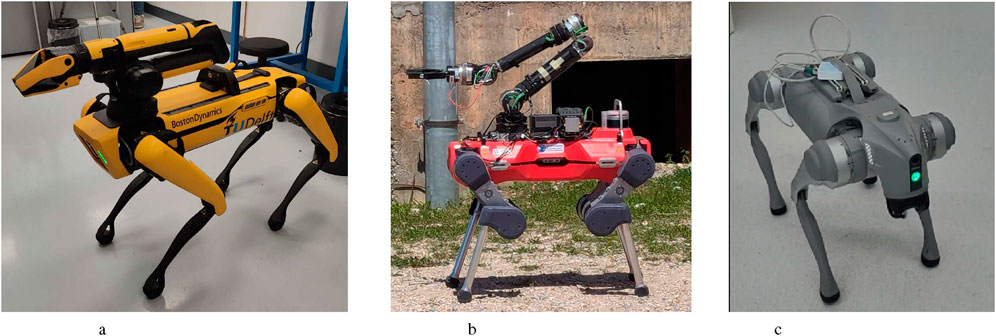
Figure 1. Commercially available quadrupedal robots from different companies: (a) Boston Dynamics Spot. (b) ANYbotics ANYmal D. (c) Unitree Robotic Go2 Edu.
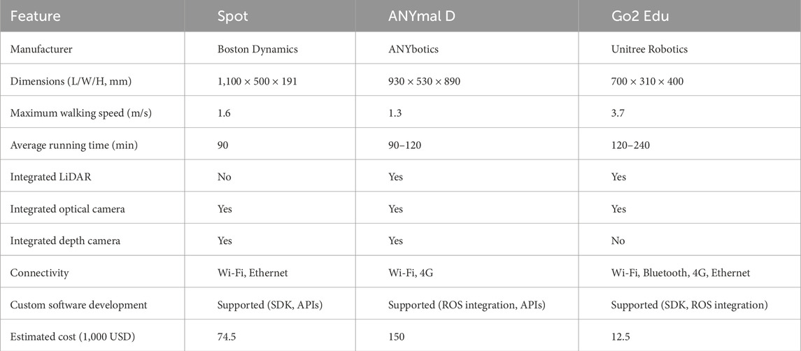
Table 1. Comparison of commercially available quadrupedal robots.
The goal of this research is to enable quadrupedal robots to map terrain using coverage path planning. To achieve this, quadrupeds require sensors—most commonly cameras (Zhang et al., 2022; Zhang et al., 2025a; Zhang et al., 2025b) and LiDAR (Bouman et al., 2022; Niu et al., 2024). In order to scan with these sensors, the robot needs to move to various points of interest (POIs), which requires coverage path planning and navigation methods. These are examined in the related works section below.
1.1 Related works
Several studies have recently explored the development of software infrastructure for the Unitree Robotics’ Go2 Edu robot. Mei et al. (2024) developed a reinforcement learning method to enable the Go2 Edu robot to navigate narrow pipes using visual inputs from a depth camera. The navigation process is relatively straightforward due to the grid-like structure of the pipes, where each pipe is aligned in a straight path, with occasional protrusions serving as obstacles. Guo et al. (2024) developed a high-level path planning using a large language model, namely, OpenAI’s ChatGPT-4o, which allows the interpretation of human verbal commands and translates them into a list of executable instructions. The system integrates a depth camera with a segmentation model to effectively perceive the environment. In addition, Cheng et al. (2024) developed a motion controller for the Go2 Edu robot to traverse complex and unstructured environments using proprioceptive sensing and collision estimation only.
Autonomous navigation using quadrupedal robots is crucial for exploring complex environments; however, research on 2D coverage path planning is limited. Ly et al. (2023) achieved coverage path planning for loco-manipulation through an integrated end-to-end pipeline combining perception, optimization, and whole-body motion planning with RGB-D camera inputs. Bouman et al. (2022) presented a 2D coverage path planner for investigating unknown and unstructured environments while accounting for time-bounded and dynamic constraints and traversability risk. The advantage of these approaches is that they guarantee timely execution when the mission is time-bound, and they find a good optimal tradeoff between the maximum area coverage and the path traveled. The drawback of these approaches is that they are focused on time constraints; therefore, they do not work when the task has a variable execution time and requires time to be defined in advance. In contrast, our approach enables planning for variable times.
Some navigation methods already enable planning for variable times. Recently, Niu et al. (2024) developed a novel autonomous exploration method that uses a topological skeleton of the environment’s geometry via LiDAR, along with a finite state machine (FSM) to enable an exploratory strategy. This was demonstrated on a quadrupedal robot in an unstructured environment. These approaches have the advantage of being very adaptable in an unknown environment due to the use of a state machine that continuously checks for undiscovered areas within the map. The main difference between this work and our approach is that their method for obtaining topological skeletons uses wave propagation and Voronoi diagrams, while our method uses a morphological technique by treating the environment as an image. The impact of this is that the morphological technique simplifies the mapping and is thus computationally more efficient.
Furthermore, all the above methods of coverage path planning have specific map generation algorithms that are an integral part of the whole approach. Therefore, they are less modular, making it difficult to replace them with developing state-of-the-art mapping algorithms. In contrast, our approach can work with different types of mapping algorithms, thus making it more modular.
1.2 Contribution
In this work, we address the gap in the state of the art through the following key contributions.
1. We develop a control framework based on a finite state machine that switches between different operation modes to enable autonomous navigation and environmental inspection.
2. Using a prior 2D navigation map of the surroundings, the framework rapidly generates an efficient path based on the morphological skeleton of the map, which ensures coverage from small to large areas.
3. We validate the developed system through on-field experiments involving navigational tasks using the Unitree Robotics Go2 Edu robot in an indoor environment.
4. We designed an extended interface that enables the Unitree Robotics Go2 Edu to integrate with the control framework using ROS 2.
5. The whole application is open source and available at https://github.com/asil-lab/go2-autonomous-navigation
2 Materials and equipment
2.1 Hardware specifications
The Unitree Robotics Go2 Edu features three degrees of freedom (DOFs) per leg, consisting of hip, thigh, and calf hinge joints (from base to foot). It is equipped with an inertial measurement unit (IMU), an HD wide-angle camera, and foot-end force sensors. The robot offers a battery life of 2–4 h and supports fast charging1.
For navigation and perception, the Go2 Edu is fitted with the Unitree L1—a 4D LiDAR (3D position + 1D greyscale) based on laser time-of-flight (TOF)—mounted on its mouth. This LiDAR provides a 360°
Furthermore, the robot includes an expansion dock that houses an NVIDIA Jetson Orin, providing computing power of 40–100 TOPS. It also comes with a manual two-handed joystick controller for user operation. Additionally, in order to monitor the robot remotely, a TP-Link TL-WR802N Nano WLAN Router is added to establish a wireless connection between the robot and the operator’s computer.
Finally, we also integrated external sensors on the robot to measure ambiance characteristics such as temperature, humidity, and light intensity. The integration of these sensors is discussed in Supplementary Material A, but their usage is outside the scope of this work and is, therefore, not detailed in this paper.
2.2 Software specifications
The Unitree Robotics Go2 Edu robot has a dedicated software development kit (SDK), which allows custom implementations to be programmed. This SDK uses a data distribution service (DDS) as the networking middleware, which enables reliable and real-time data exchange between the program and the robot3.
Using DDS, a ROS application (Macenski et al., 2022) is also implemented to facilitate seamless communication between distributed robotic components, thus ensuring real-time data exchange, scalability, and interoperability across diverse hardware and software platforms.
In particular, we use ROS 2 due to its additional benefits compared to ROS 1, such as decentralization, simplicity, and user-friendliness. We use the ROS 2 Foxy on Ubuntu 20.04 to develop our proposed framework as these specifications are well-established for the Unitree Robotics Go2 Edu robot.
2.3 SLAM
For the robot to determine its location within the environment while simultaneously creating a map, we use simultaneous localization and mapping (SLAM). SLAM allows the robot to dynamically create a map based on the history of information and localize the robot as a function of both the current measurement and the map simultaneously (Stachniss et al., 2016). In our case, a 2D map is sufficient because the robot can only navigate on the ground surface in the
Despite the strengths of Macenski’s SLAM implementation, the integrated sensor that measures the geometry of the surroundings is a LiDAR that outputs data as a 3D point cloud. To make these data interpretable by the SLAM_Toolbox, we process the LiDAR measurements to identify the obstacles that the robot cannot navigate through. To achieve this task, we develop a data processing pipeline using the Point Cloud Library (PCL) (Rusu and Cousins, 2011), which transforms the input 3D point cloud/point _cloud/raw into the desired 2D laser scans/scan. An overview of this pipeline is shown in Figure 2. Notably, this pipeline also outputs another point cloud/point_cloud/sampled, which is later used for environment scanning, as described in Supplementary Material C.
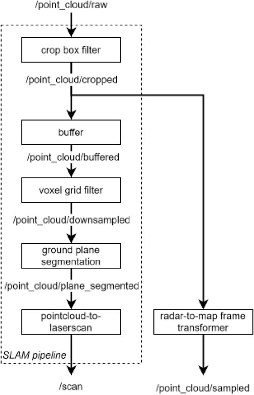
Figure 2. Pipeline diagram of filtering the point cloud for SLAM and 3D scanning per measurement update.
2.4 Navigation
We use the Nav2 framework (Macenski et al., 2023) to ensure that the robot can plan and navigate toward a desired pose (position and orientation) in the environment, which is also completely compatible with the SLAM_Toolbox discussed previously. Using the 2D navigation map provided by SLAM, the Nav2 framework can plan and navigate a path as a function of the destination’s pose, the robot’s current pose, and the robot’s kinematic constraints with respect to its surroundings. A 2D pose is defined as
The Nav2 framework includes an array of tools such as planners, recoveries, and controllers. It is outside the scope of this paper to experiment with different tools. Therefore, we mainly used the default configuration with minor adjustments that correspond to the robot’s kinematics. Since the robot’s movement can be controlled using 2D velocities
Finally, since the Nav2 framework requires a desired pose as an input, it serves as a local planner and navigator. Therefore, in order to achieve autonomy in the robot, we require a higher-level navigation approach capable of identifying and selecting ROIs to navigate within the environment.
3 Methods
In this work, we propose a novel framework for the Unitree Robotics Go2 Edu robot for navigation in unstructured and unpredictable environments. Figure 3 presents a system overview highlighting the key modules. The key modules that are responsible for the autonomous navigation are highlighted in red. To create a graph of ROIs, the map reader examines the SLAM-generated map and transforms it into a topological skeleton based on its geometry (Section 3.1). Path planning is informed by the graph, which creates an efficient path of ROIs, referred to as waypoints, that the robot must follow during navigation (Section 3.2). To control the high-level operation, a state machine (Section 3.3) is used to switch between actions, e.g., it checks when/whether each waypoint is complete, whether a fallback strategy is needed, and whether human operator input is detected. The communication between the modules is carried out via ROS 2 using an extended interface. More information on the extended interface can be found in Supplementary Material B.
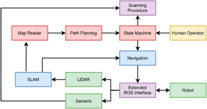
Figure 3. System overview of the proposed autonomous navigation with scanning capabilities in an unstructured environment. Green, hardware modules; blue, SLAM and Nav2 modules; red, autonomous navigation modules; purple, supplementary modules; and yellow, human agent.
3.1 Map reader
To effectively cover the environment, the robot must follow a path that ensures it traverses every corner of the space. This path should align with the trajectory of the occupied areas, e.g., corridors. This approach is generally effective under the assumption that the environment is confined within a bounded, occupied space, such as an indoor setting. In order to create the path, we process the 2D navigation map as an 8-bit array using the algorithm, as shown in Algorithm 1.
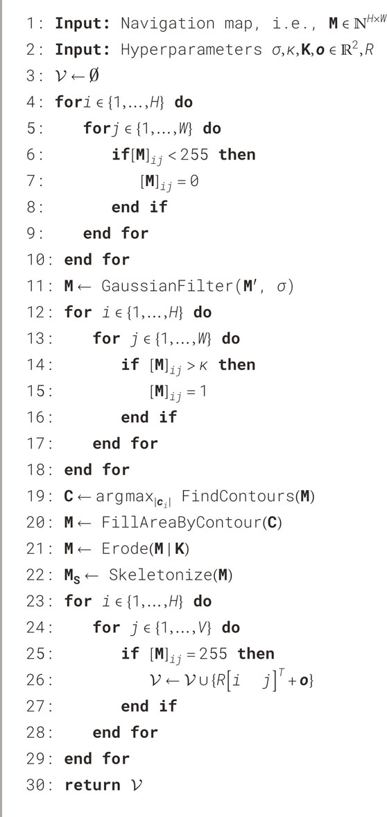
Algorithm 1. The 8-bit 2D navigation map
First, an indoor environment is considered. In such cases, most unknown cells inside the map are located outside the boundaries of the occupied area, e.g., beyond the walls. This is because SLAM initially represents the environment as a grid of unknown cells before any exploration occurs. Furthermore, unknown cells often persist between occupied and free regions as a result of occlusions encountered during raycasting-based measurements, such as those performed using LiDAR, as shown in Figure 6a. Consequently, this unknown space cannot be reached by the robot and can be treatedas part of the boundaries—i.e., as occupied space, as shown in Figure 6b.
To establish a smooth connection between occupied cells affected by noise in the map, a Gaussian filter (D’Haeyer, 1989) is applied using a standard deviation parameter
Due to residual noise and the presence of transparent obstacles, such as windows, there may be free cells that are unreachable to the robot. To mitigate this issue, we assume that the navigable space for the robot corresponds to the largest 2D contour. First, the contours within the map are found using the marching cubes algorithm (Lorensen and Cline, 1998). The map is then reconstructed by filling the largest 2D contour with a value of 255, as shown in Figure 6d. It is worth noting that by filling only the largest contour, obstacles within that contour are not takeninto account.
To ensure that the robot maintains a safe distance from the occupied space during navigation, the free space in the map is reducedusing a morphological filter called erosion (Khosravy et al., 2017), as shown in Figure 6e. Erosion uses a structuring element
The remaining free space is reduced to a thin one-pixel-wide representation containing
The 2D skeleton map
3.2 Path planning
In order to scan the whole environment, the robot should perform the scanning procedure for each waypoint. Therefore, the objective is to determine a path that includes every waypoint the robot must visit while optimizing for time efficiency. Ultimately, this can be considered a Traveling Salesman Problem (TSP), which we approach by formulating a fast and efficient path-planning algorithm. It takes a connected acyclic graph
In order to construct the graph
Algorithm 2 outlines the procedure for obtaining an efficient path
After identifying all leaf vertices, the leaf vertex closest to the robot’s current 2D position
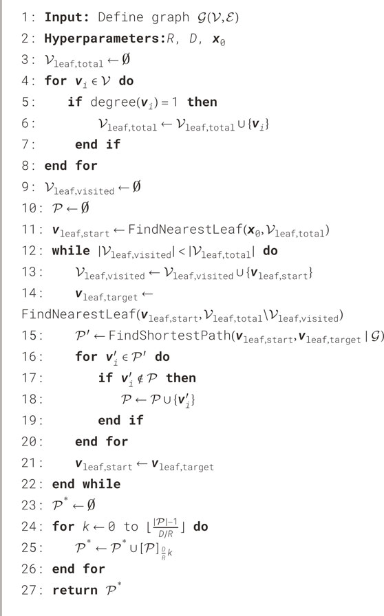
Algorithm 2. A fast and efficient approach to planning a path
Once
This is iterated until all leaf vertices have been added and
3.3 State machine
To achieve autonomy that enables the robot to visit the waypoints and perform a scanning procedure in succession, an activity diagram is formulated, as shown in Figure 4a. We can group two or more activities as a singular state if the transitions are consecutive without interruptions, e.g., a decision node. This state will perform all activities in their respective order. On the other hand, each decision node becomes a state that checks whether its control variable has reached a specified threshold. Each state has a conditionless trigger that automatically transitions the current state to the next specified state at the end of its action.
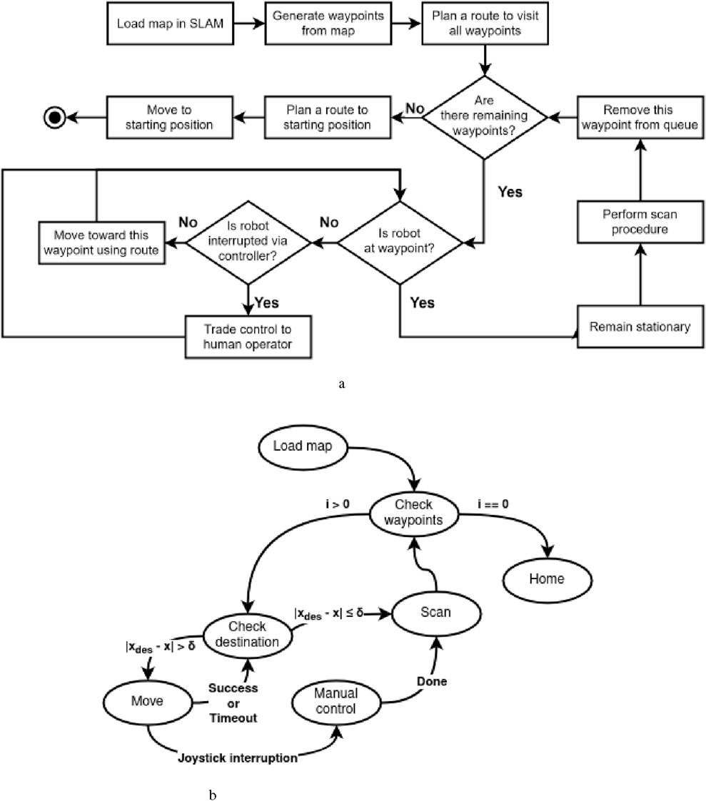
Figure 4. Comparison of (a) the activity diagram for autonomous coverage path planning and (b) its corresponding FSM diagram. (a) Activity diagram describing the autonomous coverage path planning given a prior 2D navigation map. (b) FSM diagram based on the activity diagram.
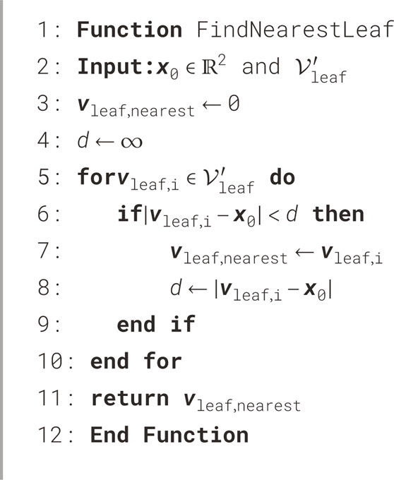
Algorithm 3. A method to find the nearest leaf vertex
With a FSM, we can achieve the desired autonomous navigation based on the triggers by handling the sequence of actions. The implemented state machine diagram is shown in Figure 4b. Each state is explained as follows:
To sum up, the proposed framework for navigation consists of three key modules: the map reader to extract POIs using the 2D navigation map as waypoints, the path planner to order the waypoints as an efficient route given the robot’s current position, and the state machine to enable the robot to navigate toward every waypoint and scan consecutively.
4 Results
To demonstrate the proposed framework and evaluate how well it performs, we conducted the experiment in a level, indoor, obstacle-free, non-convex environment. For evaluation, we used the two following metrics:
1. Time efficiency: the time required to process the map to create a path and reach each waypoint consecutively.
2. Reachability: the number of waypoints that the robot can reach over the total number of waypoints planned in %.
The Go2 Edu robot was initially manually controlled via a wireless controller to generate a 2D navigation map using the SLAM module. The experiment was then conducted, and the whole process was repeated over five trials. The SLAM module’s map resolution was set to 0.10 m. The point cloud buffer time was set to 0.25 s. The laser scan’s minimal and maximal ranges were set to 0.50 m and 30.0 m, respectively. The smoothing standard deviation was set to three. The crispification threshold was set to 128. The erosion kernel
4.1 SLAM, map reader, and path planning
Before presenting the main results, we first validate the accuracy of the 2D navigation maps generated by the SLAM module. The average map is derived by normalizing over the five 2D navigation maps obtained from five trials, as illustrated in Figure 5. The width and height of these maps range between [196,225] and [185,231] pixels, respectively. We take the inner corner of the left- wing (upper left triangle of the map) of the room as the origin to align the maps in position and orientation accordingly. Analysis of the averaged map reveals that the right wing exhibits a wider range of shades of gray about the occupied space, suggesting that this part of the environment is slightly tilted relative to its actual orientation. Nonetheless, this does not severely affect the map reader, path planning, and navigation as the robot mainly localizes itself in its immediate surroundings and the topological skeleton of the map can still be found. For instance, as shown in Figure 6, the map reader can still create waypoints mainly using the map’s geometry, which also enables the robot to visit the corners by producing branches from the main path to these corners.
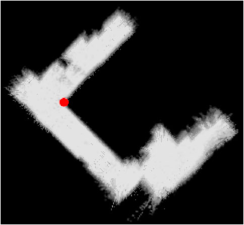
Figure 5. Derivation by normalizing over the five 2D navigation maps obtained from five trials, where the inner corner of the left wing of the room is taken as the origin, which is denoted as a red point. All five maps are translated and rotated around the red point accordingly.
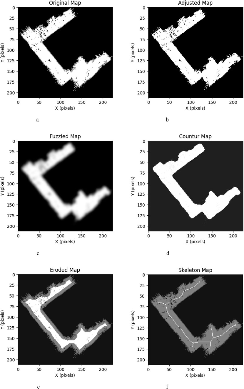
Figure 6. Demonstration of the map reader’s pipeline using the 2D navigation map of trial 5 as input. (a) Original map. (b) Adjusted map. (c) Fuzzied map. (d) Contour map. (e) Eroded map. (f) Skeleton map.
To evaluate the time efficiency of the map reader, we record the duration required to process each map across five trials, considering a total of
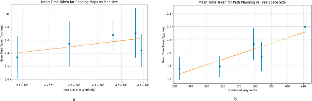
Figure 7. Comparison of the mean time taken for (a) map reader and (b) path planner over five trials. (a) Mean time taken for map reader over five trials, iterated over N = 100 plotted in blue dots, with standard deviation in 1σ as the vertical blue line. Trend line is 22.0 ns/pixel. (b) Mean time taken for path planner over five trials, iterated over N = 500 plotted in blue dots, with standard deviation in 1σ as the vertical blue line. Trend line is 8.17 μs/pixel.
To remain within a maximum time taken of 1.0 s, the map should not be larger than the size of
To determine the path planner’s time efficiency, we repeat the same process with the evaluation of the map reader over
To stay within a lead time of 1.0 s, the number of waypoints should not be larger than
To verify the path planner’s performance, we first evaluate the logic of whether it works as intended. Using one trial as an example, we observe that the path planner has created an optimal path in terms of time, based on the given waypoints and the robot’s current 2D position, as shown in Figure 8a. Furthermore, according to Figure 8b, we can observe that the mean waypoint–waypoint distance is approximately 1.00 m, given the previously set waypoint resolution
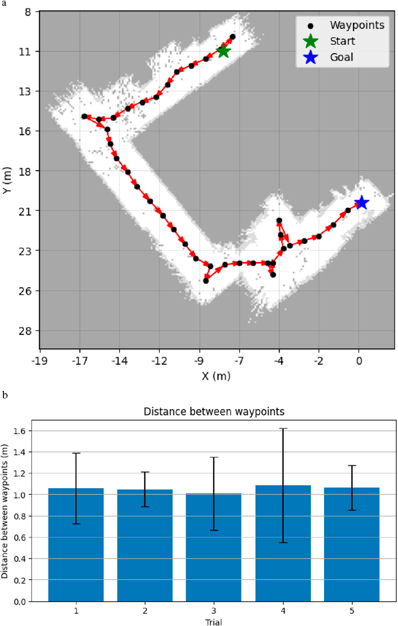
Figure 8. Demonstrations of path planner’s performance. (a) An efficient path to explore the whole environment from the robot’s starting position (green) to the farthest waypoint (blue) while visiting all other waypoints (black). Each arrow (red) denotes the direction from the source to the target. (b) Mean distance between every two connected waypoints generated by the path planning per trial, as defined by the waypoint resolution D.
4.2 Navigational performance
To determine the robot’s navigational performance, we evaluate it according to the two aforementioned metrics, as shown in Table 2. In addition, Figure 9 shows the time taken for each waypoint over all trials. We can observe that the robot is able to reach 86.5% of the total waypoints across all trials, with a median time of 5.38 s per waypoint. As shown in Figure 9, this was achieved in an average time of 8.525 s, with a standard deviation of 11.4 s.
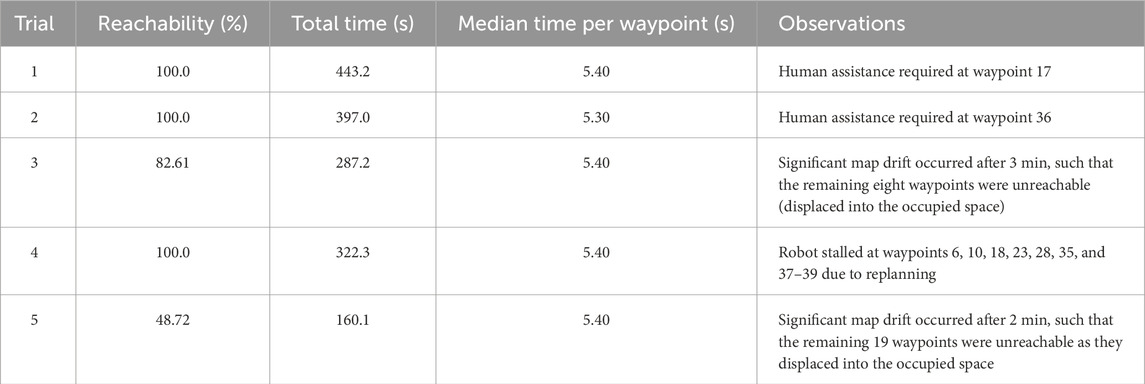
Table 2. Reachability and time taken for each trial, including key observations.
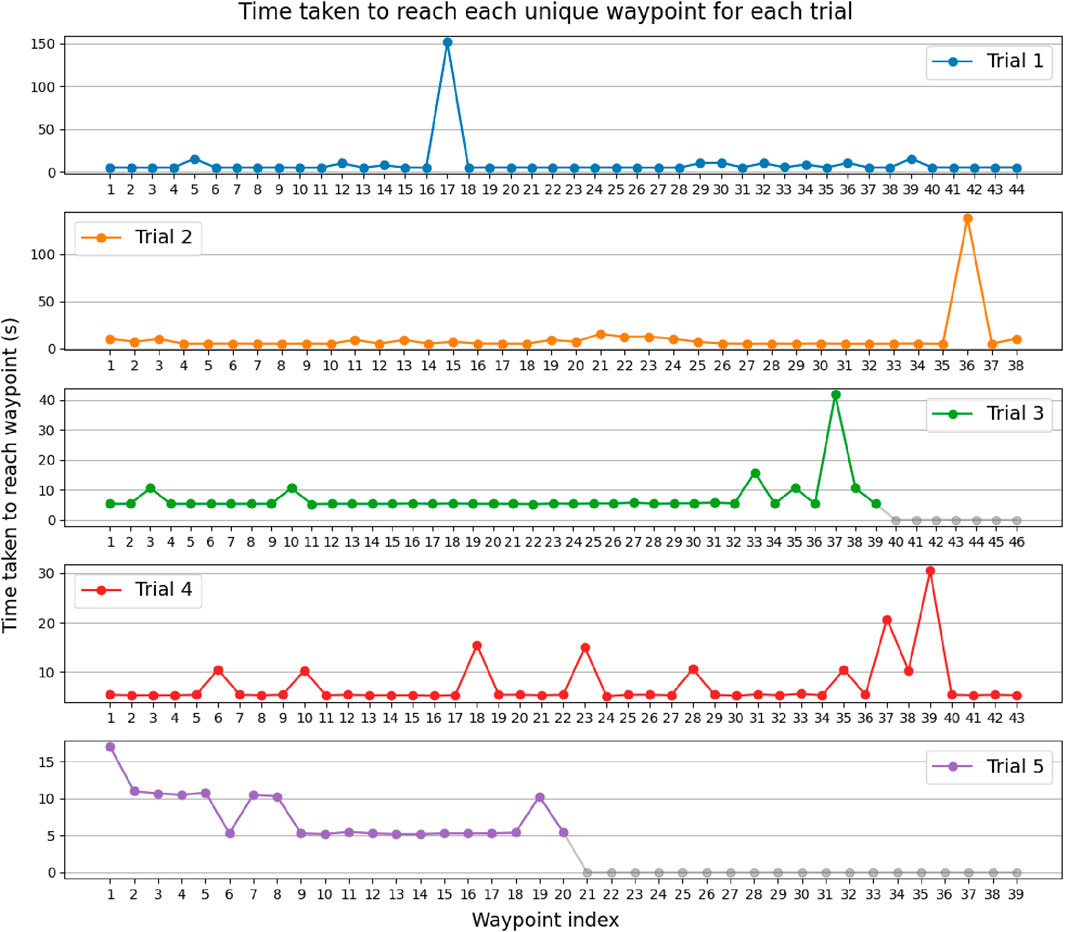
Figure 9. Time taken in seconds for the robot to reach each possible unique waypoint over five trials. Gray dots describe waypoints that the robot has not been able to reach. The outliers occurred due to Nav2 getting stuck at replanning, such that the navigation terminates within narrow desired tolerances, or due to map drift.
We can see several outliers where the robot took time ranging from 10.0 s to a few minutes to complete the navigation to the adjacent waypoint, for instance, at waypoint 17 in trial 1. This can be explained by Nav2 trying to create a local path that ends precisely within the desired tolerances in position and orientation, and because the robot requires a minimal input velocity in order to move, it overshoots the target, causing Nav2 to replan the local path. This can result in the robot becoming stuck indefinitely and requires assistance from a human operator. For some of these outliers, ranging from 30 s, human assistance is eventually required to reposition the robot correctly within the desired position and orientation tolerance.
Furthermore, Table 2 shows that in trials 3 and 5, the robot failed to reach all of the waypoints. This is mainly due to map drifts that occur over time and the fact that the SLAM module was still operating by mapping the robot’s surroundings online. This can be recognized, e.g., as two identical hallways slightly tilted relative to one another, as shown in Figure 10. Due to the drift in the navigation map, since the coordinates of the waypoints remain the same, SLAM adjusts the 2D navigation map such that the later waypoints appear in places that the robot cannot reach, such as in the walls. Drift usually occurs because we only use relative sensors to localize itself with respect to the surroundings, e.g., IMU, leg encoders, and LiDAR. This can cause the uncertainty to increase over time, which is inherent in odometry.
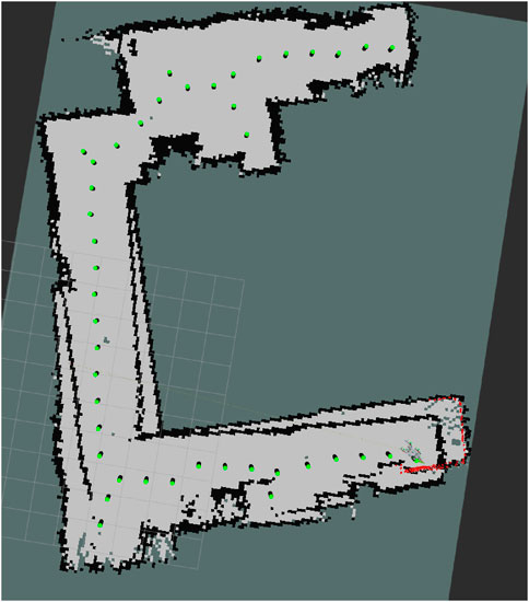
Figure 10. Drift in the map where the hall is doubled. The drift occurred 10 min after the autonomous navigation started in trial 3.
5 Discussion
Coverage path planning allows mobile robots such as quadrupeds to explore the whole environment. This is especially useful for applications such as surveillance, inspection, and search and rescue. Nevertheless, limited work has been carried out on autonomous navigation using coverage path planning on quadrupeds. Therefore, we developed an open-source framework using ROS 2 that enables a Unitree Robotics Go2 quadruped to autonomously navigate and visit every corner using a prior 2D navigation map. It utilizes a map reader to extract a graph of 2D waypoints using the topological skeleton of the map and a path planner to create an efficient path with respect to time and the starting position. A state machine is used to iterate over the ordered list of waypoints and navigate them in succession.
The map reader and the path planner can quickly process maps with widths and heights ranging from 196,225 pixels to 185,231 pixels in 2.52 ms and 1.7 ms, respectively. Their computation times increase with 22.0 ns/pixel and 8.17 μs/pixel, respectively. In a closed and unstructured environment, the robot managed to reach 86.5% of all waypoints over five runs. The failure can be explained due to drifts occurring in the maps over time because SLAM still operates online. Map drifts can be mitigated using absolute sensors such as global positioning system (GPS) and ultra-wideband anchors. Another issue that our path planning does not take into account is obstacles inside the large free space. This can be mitigated by subtracting the contours of said obstacles from the large free space. Skeletonization will account for the creation of waypoints around these occupied spaces. However, the presence of obstacles may necessitate adjustment to the path planner as they can give rise to cyclical graphs.
Compared to the state-of-the-art methods that use time-constrained planning (Bouman et al., 2022; Ly et al., 2023) and do not enable variable task execution times, our approach is not constrained by a predefined time. While a time-constrained approach is useful when the mission time is predefined, the variable-time approach provides a more adaptable solution when operating with limited knowledge. Unlike alternative state-of-the-art approaches that enable time-variable exploration (Niu et al., 2024), our approach is more computationally efficient due to the use of a morphological technique to extract the topological skeleton of the map. Even though the experimental conditions were different, a rough comparison of the map generation magnitude based on the results from each paper shows an order-of-magnitude difference (milliseconds vs. microseconds).
Nevertheless, the proposed method is primarily suited for known and static environments, rendering it unsuitable for real-world applications with irregular and moving obstacles within the environment and varying elevations. Future work will, therefore, focus on extending the proposed method to incorporate real-time autonomous coverage exploration in unknown 3D environments, particularly under diverse environmental conditions and in the presence of irregular and dynamic obstacles. Additionally, the influence of variations in key parameters will be systematically investigated. Moreover, the study will also investigate and aim to improve drift issues commonly encountered in SLAM. Finally, the proposed approach will be systematically compared with existing 2D coverage path planning methods to evaluate its relative performance and advantages.
Data availability statement
The raw data supporting the conclusions of this article will be made available by the authors, without undue reservation.
Author contributions
AJB: Software, Methodology, Writing – review and editing, Supervision, Investigation, Conceptualization, Writing – original draft, Funding acquisition, Data curation, Visualization, Formal Analysis, Project administration, Resources, Validation. KK: Methodology, Writing – review and editing, Software, Investigation, Supervision, Funding acquisition, Conceptualization, Visualization, Resources, Validation, Data curation, Formal Analysis, Project administration. LP: Project administration, Formal Analysis, Validation, Visualization, Methodology, Data curation, Conceptualization, Writing – original draft, Software, Writing – review and editing, Funding acquisition, Supervision, Resources, Investigation. RR: Conceptualization, Resources, Formal Analysis, Funding acquisition, Validation, Visualization, Project administration, Writing – original draft, Investigation, Supervision, Data curation, Methodology, Writing – review and editing, Software.
Funding
The author(s) declare that financial support was received for the research and/or publication of this article. The work was partially supported by the TU Delft Moonshot.
Conflict of interest
The authors declare that the research was conducted in the absence of any commercial or financial relationships that could be construed as a potential conflict of interest.
Generative AI statement
The author(s) declare that no Generative AI was used in the creation of this manuscript.
Publisher’s note
All claims expressed in this article are solely those of the authors and do not necessarily represent those of their affiliated organizations, or those of the publisher, the editors and the reviewers. Any product that may be evaluated in this article, or claim that may be made by its manufacturer, is not guaranteed or endorsed by the publisher.
Supplementary material
The Supplementary Material for this article can be found online at: https://www.frontiersin.org/articles/10.3389/frobt.2025.1601862/full#supplementary-material
Footnotes
1Go2 SDK Development Guide - About Go2 https://support.unitree.com/home/en/developer/about_Go2
2 4D Lidar L1 Application Scenarios 4D Lidar L1 Efficacy — Unitree Robotic https://www.unitree.com/LiDAR
3Go2 SDK Development Guide - SDK Concepts https://support.unitree.com/home/en/developer/SDK_Concepts
References
Ai, X., Xu, C., Li, B., and Xia, F. (2024). Robot-as-A-sensor: forming a sensing network with robots for underground mining missions, doi:10.48550/arXiv.2405.00266
Arm, P., Zenkl, R., Barton, P., Beglinger, L., Dietsche, A., Ferrazzini, L., et al. (2019). “Spacebok: a dynamic legged robot for space exploration,” in 2019 international conference on robotics and automation (ICRA), 6288–6294. doi:10.1109/ICRA.2019.8794136
Barbehenn, M. (1998). A note on the complexity of dijkstra’s algorithm for graphs with weighted vertices. IEEE Trans. Comput. 47, 263. doi:10.1109/12.663776
Bouman, A., Ott, J., Kim, S.-K., Chen, K., Kochenderfer, M. J., Lopez, B., et al. (2022). “Adaptive coverage path planning for efficient exploration of unknown environments,” in 2022 IEEE/RSJ International Conference on Intelligent Robots and Systems (IROS), 11916–11923. doi:10.1109/IROS47612.2022.9982287
Candalot, A., Hashim, M.-M., Hickey, B., Laine, M., Hunter-Scullion, M., and Yoshida, K. (2024). Soft gripping system for space exploration legged robots. 144, 156. doi:10.1007/978-3-031-71301-9_14
Chagoya, J., Patel, S., Koduru, C., Kovarovics, A., Tanveer, M. H., and Voicu, R. C. (2024). Data collection, heat map generation for crack detection using robotic dog fused with flir sensor. SoutheastCon 2024, 824–829. doi:10.1109/SoutheastCon52093.2024.10500184
Chai, H., Li, Y., Song, R., Zhang, G., Zhang, Q., Liu, S., et al. (2022). A survey of the development of quadruped robots: joint configuration, dynamic locomotion control method and mobile manipulation approach. Biomim. Intell. Robotics 2, 100029. doi:10.1016/j.birob.2021.100029
Chen, Z., Wu, H., Chen, Y., Cheng, L., and Zhang, B. (2022). Patrol robot path planning in nuclear power plant using an interval multi-objective particle swarm optimization algorithm. Appl. Soft Comput. 116, 108192. doi:10.1016/j.asoc.2021.108192
Cheng, Y., Liu, H., Pan, G., Liu, H., and Ye, L. (2024). “Quadruped robot traversing 3d complex environments with limited perception,” in 2024 IEEE/RSJ International Conference on Intelligent Robots and Systems (IROS), 9074–9081. doi:10.1109/IROS58592.2024.10801507
Chiou, M., Epsimos, G.-T., Nikolaou, G., Pappas, P., Petousakis, G., Mühl, S., et al. (2022). “Robot-assisted nuclear disaster response: report and insights from a field exercise,” in 2022 IEEE/RSJ International Conference on Intelligent Robots and Systems (IROS), 4545–4552. doi:10.1109/IROS47612.2022.9981881
D’Haeyer, J. P. (1989). Gaussian filtering of images: a regularization approach. Signal Process. 18, 169–181. doi:10.1016/0165-1684(89)90048-0
Fan, Y., Pei, Z., Wang, C., Li, M., Tang, Z., and Liu, Q. (2024). A review of quadruped robots: structure, control, and autonomous motion. Adv. Intell. Syst., 6, 2300783. doi:10.1002/aisy.202300783
Guo, J., Wang, Z., and Bai, W. (2024). Learning quadrupedal robot locomotion for narrow pipe inspection. arXiv, doi:10.48550/arXiv.2412.13621
Jiang, Z., Cao, X., Huang, X., Li, H., and Ceccarelli, M. (2022). Progress and development trend of space intelligent robot technology. Space Sci. and Technol. 2022, 2022. doi:10.34133/2022/9832053
Khosravy, M., Gupta, N., Marina, N., Sethi, I. K., and Asharif, M. R. (2017). Morphological filters: an inspiration from natural geometrical erosion and dilation. Cham: Springer International Publishing, 349–379. doi:10.1007/978-3-319-50920-4_14
Lin, T.-H., Huang, J.-T., and Putranto, A. (2022). Integrated smart robot with earthquake early warning system for automated inspection and emergency response. Nat. hazards 110, 765–786. doi:10.1007/s11069-021-04969-2
Lorensen, W. E., and Cline, H. E. (1998). Marching cubes: a high resolution 3D surface construction algorithm. New York, NY, USA: Association for Computing Machinery, 347–353. doi:10.1145/280811.281026
Ly, K. T., Munks, M., Merkt, W., and Havoutis, I. (2023). “Asymptotically optimized multi-surface coverage path planning for loco-manipulation in inspection and monitoring,” in 2023 IEEE 19th International Conference on Automation Science and Engineering (CASE), 1–7. doi:10.1109/CASE56687.2023.10260625
Macenski, S., Foote, T., Gerkey, B., Lalancette, C., and Woodall, W. (2022). Robot operating system 2: design, architecture, and uses in the wild. Sci. Robotics 7, eabm6074. doi:10.1126/scirobotics.abm6074
Macenski, S., and Jambrecic, I. (2021). Slam toolbox: slam for the dynamic world. J. Open Source Softw. 6, 2783. doi:10.21105/joss.02783
Macenski, S., Moore, T., Lu, D. V., Merzlyakov, A., and Ferguson, M. (2023). From the desks of ROS maintainers: a survey of modern and capable mobile robotics algorithms in the robot operating system 2. Robotics Aut. Syst., doi:10.1016/j.robot.2023.104493
Mei, Y., Wang, Y., Zheng, S., and Jin, Q. (2024). QuadrupedGPT: towards a versatile quadruped agent in open-ended worlds. arXiv, doi:10.48550/arXiv.2406.16578
Miller, I. D., Cladera, F., Cowley, A., Shivakumar, S. S., Lee, E. S., Jarin-Lipschitz, L., et al. (2020). Mine tunnel exploration using multiple quadrupedal robots. IEEE Robotics Automation Lett. 5, 2840–2847. doi:10.1109/LRA.2020.2972872
Nitulescu, M., Ivanescu, M., Hai Nguyen, V. D., and Manoiu-Olaru, S. (2016). “Designing the legs of a hexapod robot,” in 2016 20th International Conference on System Theory, Control and Computing (ICSTCC), 119–124. doi:10.1109/ICSTCC.2016.7790651
Niu, H., Ji, X., Zhang, L., Wen, F., Ying, R., and Liu, P. (2024). A skeleton-based topological planner for exploration in complex unknown environments, doi:10.48550/arXiv.2412.13664
Paredes, D., and Fleming-Muñoz, D. (2021). Automation and robotics in mining: jobs, income and inequality implications. Extr. Industries Soc. 8, 189–193. doi:10.1016/j.exis.2021.01.004
Portela, T., Cramariuc, A., Mittal, M., and Hutter, M. (2024). Whole-body end-effector pose tracking, doi:10.48550/arXiv.2409.16048
Rajan, R. T., Menicucci, A., Noroozi, A., Sachdeva, P., and Verhoeven, C. (2024). “Lunar zebro †an autonomous moon rover,” in IAF space exploration symposium. doi:10.52202/078357-0039
Rusu, R. B., and Cousins, S. (2011). “3D is here: point cloud library (PCL),” in IEEE International Conference on Robotics and Automation (ICRA), Shanghai, China. doi:10.1109/ICRA.2011.5980567
Sharma, U., Medasetti, U. S., Deemyad, T., Mashal, M., and Yadav, V. (2024). Mobile robot for security applications in remotely operated advanced reactors. Appl. Sci. 14, 2552. doi:10.3390/app14062552
Solmaz, S., Innerwinkler, P., Wãjcik, M., Tong, K., Politi, E., Dimitrakopoulos, G., et al. (2024). “Robust robotic search and rescue in harsh environments: an example and open challenges,” in 2024 IEEE international symposium on robotic and sensors environments (ROSE), 1–8. doi:10.1109/ROSE62198.2024.10591144
Stachniss, C., Leonard, J. J., and Thrun, S. (2016). Simultaneous localization and mapping. Cham: Springer International Publishing, 1153–1176. doi:10.1007/978-3-319-32552-1_46
Yin, Y., Zhao, Y., Xiao, Y., and Gao, F. (2023). Footholds optimization for legged robots walking on complex terrain. Front. Mech. Eng. 18, 26. doi:10.1007/s11465-022-0742-y
Zhang, R., Cao, Z., Huang, Y., Yang, S., Xu, L., and Xu, M. (2025a). Visible-infrared person re-identification with real-world label noise. IEEE Trans. Circuits Syst. Video Technol. 35, 4857–4869. doi:10.1109/TCSVT.2025.3526449
Zhang, R., Xu, L., Yu, Z., Shi, Y., Mu, C., and Xu, M. (2022). Deep-irtarget: an automatic target detector in infrared imagery using dual-domain feature extraction and allocation. IEEE Trans. Multimedia 24, 1735–1749. doi:10.1109/TMM.2021.3070138
Zhang, R., Yang, B., Xu, L., Huang, Y., Xu, X., Zhang, Q., et al. (2025b). A benchmark and frequency compression method for infrared few-shot object detection. IEEE Trans. Geoscience Remote Sens. 63, 1–11. doi:10.1109/TGRS.2025.3540945
Keywords: quadruped, autonomous navigation, unstructured environment, coverage path planning, robot operating system 2
Citation: Becoy AJ, Khomenko K, Peternel L and Rajan RT (2025) Autonomous navigation of quadrupeds using coverage path planning with morphological skeleton maps. Front. Robot. AI 12:1601862. doi: 10.3389/frobt.2025.1601862
Received: 28 March 2025; Accepted: 04 June 2025;
Published: 31 July 2025.
Edited by:
Ziliang Kang, Massachusetts Institute of Technology, United StatesReviewed by:
Ruiheng Zhang, Beijing Institute of Technology, ChinaKaoru Yamamoto, Kyushu University, Japan
Jiajie Qiu, Massachusetts Institute of Technology, United States
Copyright © 2025 Becoy, Khomenko, Peternel and Rajan. This is an open-access article distributed under the terms of the Creative Commons Attribution License (CC BY). The use, distribution or reproduction in other forums is permitted, provided the original author(s) and the copyright owner(s) are credited and that the original publication in this journal is cited, in accordance with accepted academic practice. No use, distribution or reproduction is permitted which does not comply with these terms.
*Correspondence: Luka Peternel, bC5wZXRlcm5lbEB0dWRlbGZ0Lm5s