 Laura Bastianini1*
 Mike Rogerson1
 Ramon Mercedes-Martín2
 Timothy J. Prior3
 Edgley A. Cesar4
 William M. Mayes1
- 1Department of Geography, Geology and Environment, Faculty of Science and Engineering, University of Hull, Hull, United Kingdom
- 2SZALAI Grup, Caimari, Spain
- 3Department of Chemistry and Biochemistry, Faculty of Science and Engineering, University of Hull, Hull, United Kingdom
- 4LS Algae, Fungi and Plants Division, Department of Life Sciences, Natural History Museum, London, United Kingdom
The South Atlantic Aptian “Pre-Salt” shrubby carbonate successions offshore Brazil and Angola are of major interest due to their potential hydrocarbon accumulations. Although the general sedimentology of these deposits is widely recognized to be within saline, alkaline lakes in rift volcanic settings, the specific genesis of shrubby carbonate morphologies remains unclear. This study reports the first petrographically comparable shrubby carbonates amongst other carbonate microfacies from an Anthropocene limestone formed under hyperalkaline (pH 9–12) and hypersaline (conductivity 425–3200 μS) conditions at ambient temperature (12.5–13°C) (Consett, United Kingdom). This discovery allows us to capitalize on exceptional long-term hydrochemical monitoring efforts from the site, demonstrating that shrubby carbonates occur uniquely within the waters richest in calcium (∼240 mg/L) and with highest pH (∼12) and consequently with very high levels of supersaturation. However, the physical distribution of shrubs is more comparable with estimated local kinetic precipitation rate than it is to thermodynamic saturation, indicating that the fundamental control on shrub formation arises from crystal surface processes. The shrubby carbonate we report grows in the presence of significant diatomaceous and cyanobacterial biofilms, despite the highly alkaline conditions. These biofilms are lost from the deposited material early due to the high solubility of organic and silica within hyperalkaline settings, and this loss contributes to very high intercrystalline porosity. Despite the presence of these microbes, few if any of the fabrics we report would be considered as “boundstones” despite it being clear that most fabrics are being deposited in the presence of abundant extra-cellular polymeric substances. We are aware of no previous petrographic work on anthropogenic carbonates of this type, and recommend further investigation to capitalize on what can be learned from these “accidental laboratories.”
Introduction
The genesis and evolution of Lower Cretaceous, non-marine carbonate hydrocarbon reservoirs in the South Atlantic, with their voluminous shrubby and spherulitic carbonate deposits in a volcanic and alkaline lacustrine setting, remains an enigma (Mercedes-Martín et al., 2016, 2017; Wright and Tosca, 2016). Two main mechanisms for spherulite formation have been presented, with formation within a transient Mg–Si gel (Wright and Barnett, 2015; Wright and Tosca, 2016; Tosca et al., 2018) or as a result of organic acid binding to growing crystal surfaces (Chafetz and Butler, 1980; Tucker and Wright, 2009; Spadafora et al., 2010; Mercedes-Martín et al., 2016, 2017). Both mechanisms suggest a saline, alkaline environment, and high metal fluxes are required to emplace these large Ca- and Mg-dominated precipitate bodies. The “shrubby” spherulitic boundstones which generally form the best reservoir facies (Ceraldi and Green, 2016; Saller et al., 2016) are less well understood, and are generally assumed to be some local modification of the more common spherular growth-form. Recent examples of shrubby carbonate formation are hard to find, reflecting that the microenvironment in which these growth-forms develop are not well represented in the modern Earth system. One explanation for the origin of the high flux of metalliferous, alkaline water to the Pre-Salt lakes is hydrolysis of fresh alkaline extrusive igneous materials (Rogerson et al., 2017), and partial analogs of Pre-Salt mineralogies and fabrics do occur in ophiolite spring systems (from Oman and Liguria) (Leleu et al., 2016). Here, the alteration of mafic/ultramafic rocks by meteoric waters and seawater provides saline, hyperalkaline (pH ∼ 10) waters which in-gas carbon dioxide from the atmosphere. These ambient temperature systems are subtly different to more conventional travertine systems, which are usually located at subaerial hot springs such as Mammoth Hot Springs in Wyoming (Ford and Pedley, 1996; Fouke et al., 2000). In geothermal systems, CO2 is available from the deep subsurface in surplus to the metals (Minissale et al., 1997), making carbonate production calcium-limited. In contrast, within non-geothermal systems driven by mineral hydrolysis, all CO2 is provided from atmosphere and the carbonate system tends to be limited by the relatively slow kinetics of CO2(g) dissolution and hydrolysis to rather than the abundance of calcium (Andrews et al., 1997; Rogerson et al., 2017).
Here, we provide the first report of shrubby carbonates forming today within another carbonate forming system driven by mineral hydrolysis; terrestrial surface waters affected by leachate from steel slag stored in landfill, which are forming significant deposits of Anthropocene Limestone. Our case study, Consett in the United Kingdom, exhibits pH even higher than in the ophiolite springs (9–13), and supports exceptional rates of calcite precipitation (up to 100 g m–2 day–1) (Mayes et al., 2008). The diversity and extremely good preservation of the crystals from these carbonates, exceptionally well constrained local hydrochemical environment (Mayes et al., 2008, 2018; Riley and Mayes, 2015) and the possibility to directly observe the co-occurrence of specific growth-forms and microbial components at sites of deposition provides a unique opportunity to test hypotheses concerning the mechanics of exotic calcium carbonate crystal growth patterns in nature. This study is the first report of carbonate petrography from this “accidental laboratory” and raises the following question: What carbonate fabrics can emerge from extreme alkaline conditions? Although it is rather unlikely Aptian Pre-Salt lakes were forming downstream of dinosaurian steel works, the probability is high that the lakes were the sinks of calcium and alkalinity sourced by cool mineral hydrolysis, making the geochemistry and sedimentology of these systems cognate. We explore what additional constraints we can now place on Pre-Salt lakes on the basis of discovering the same fabrics within Anthropocene carbonate sediments.
Materials and Methods
Field-Work Methods
Samples were taken during May 2013 along pre-established calcite saturation index transects (Mayes et al., 2008, 2018; Riley and Mayes, 2015) within Dene Burn and Howden Burn (Figure 1) for further analyses in the laboratory. In these streams, calcite saturation is enhanced by four alkaline discharges within the former Consett Iron and Steelworks. The site was operational from the middle of the nineteen century until decommissioning in the early 1908s (Figure 1). Waste up to 45 m depth, including slag, flue dusts, ashes and construction and demolition rubble were accumulated after working closure in an area of 2.9 km2 (Harber and Forth, 2001). These materials are now stored in landfill, and the leachates emerging from them are alkaline ([OH–] = 10–130 mg.L–1; [CO32–] = 10–110 mg.L–1; [HCO3–] = 110 mg.L–1) because of the bulk chemical composition meteoric waters develop after inter-acting with these materials in the subsurface (Mayes et al., 2008, 2018; Riley and Mayes, 2015).
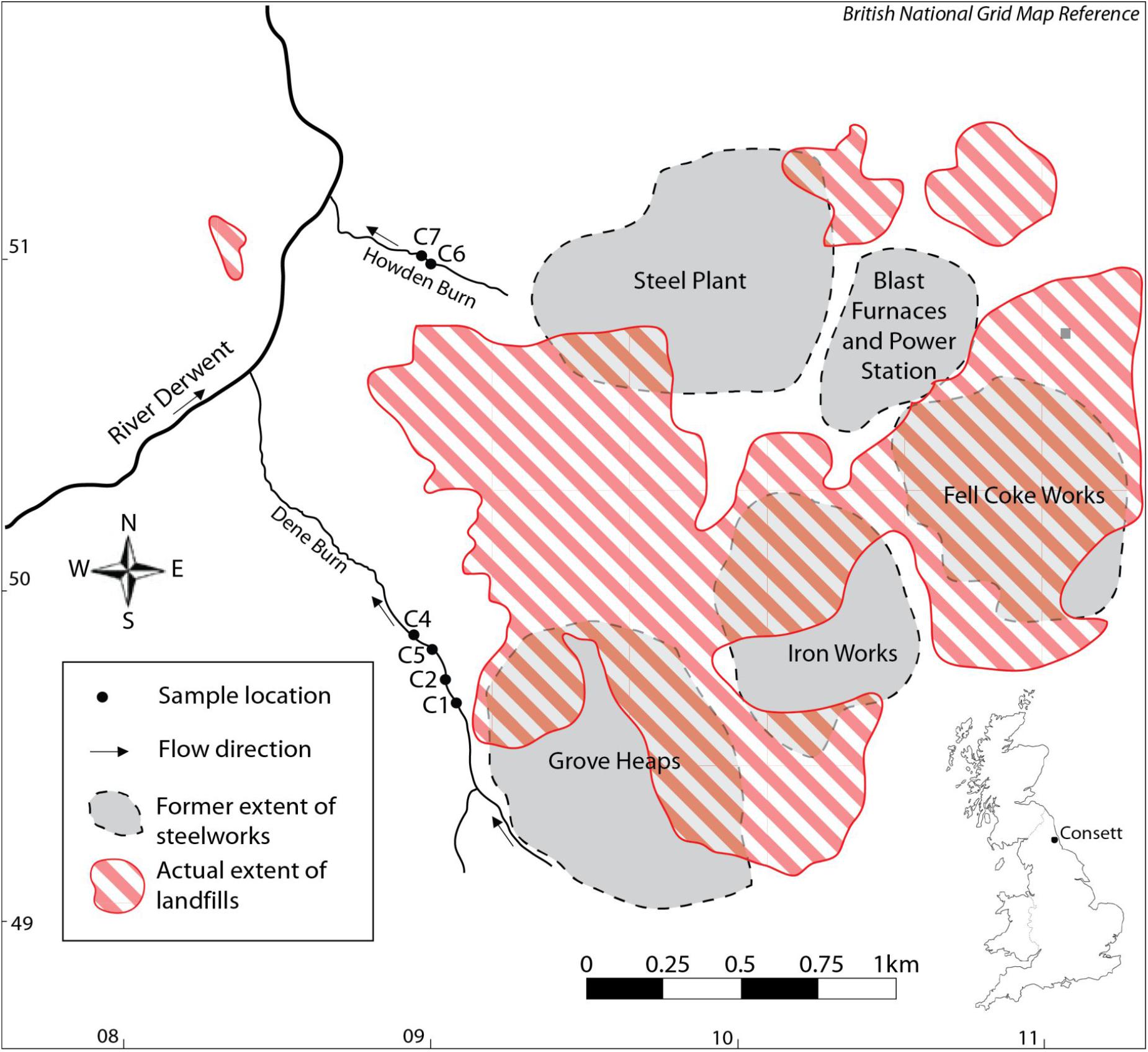
Figure 1. Location map of the studied samples HU-MR-/3CON1 (C1), HU-MR-/3CON2 (C2), HU-MR-/3CON4 (C4), HU-MR-/3CON5 (C5), HU-MR-/3CON6 (C6), HU-MR-/3CON7 (C7).
These landfills can be a source of pollution to surface and ground waters (Mayes et al., 2008) (Figure 1). The production of iron results in the emission of sulfur dioxide gas, ore and coke dust particles (Harber and Forth, 2001). Other potential contaminants such as arsenic, chromium, boron and copper are present in iron ore (Harber and Forth, 2001). Coke making provides inorganic compounds, for example zinc, fluoride, sulfates, phosphates and organic compounds such as fuels and oils (Harber and Forth, 2001). Iron and steel flue dusts contain metals including lead, cadmium, halides, zinc, chromium, arsenic, copper, nickel, and alkali metals (Harber and Forth, 2001). Fluoride and zinc are the main pollutants of steel-making wastewaters (Harber and Forth, 2001).
Half of Dene Burn flow comes from a subterranean drainage network beneath the Grove Heaps which consist of blast furnace bottom and steel slag (Mayes et al., 2008), whereas the Howden burn drains an area previously occupied by the working blast furnaces, power station and steel plant (Mayes et al., 2008) (Figure 1). The hydrochemical facies of the leachates are seen to vary notably between the landfills resulting in the streams Howden Burn and Dene Burn (Mayes et al., 2008) (Figure 1). Dene Burn leachate source is dominated by Ca, Mg and HCO3 characteristic of Coal Measures drainage in the region and Ca-OH type leachate from the dissolution of portlandite in the steel slag mounds (Mayes et al., 2008). Dene Burn source leachate also shows elevated Na and Cl concentrations from de-icing salt runoff (Mayes et al., 2008). Howden Burn leachate sources differ considerably from Dene Burn drainage system and are mixed waters rich in K, Na, Ca, and sulfate (Mayes et al., 2008) (Figure 1). Sulfate concentrations are exceptionally elevated [2,500 mg.L–1] typical of a drainage from the former power station and coke works area of the workings (Figure 1). Within these locations, coke works spoil, ashes, and iron slags, which have a high sulfur content, were co-deposited with steel and blast furnace slag (Harber and Forth, 2001). The extremely important K content of Howden Burn leachate sources probably derive from highly soluble potassium oxides associated with flue dusts and ashes deposited with slag (Mayes et al., 2008).
Four samples reported here (HU-MR-/3CON1, HU-MR-/3CON2, HU-MR-/3CON4, HU-MR-/3CON5) are from Dene Burn (Figure 1) and further two samples (HU-MR-/3CON6, HU-MR-/3CON7) originate from Howden Burn (Figure 1).
During our sampling, on-site measurements of major physico-chemical parameters (pH, electrical conductivity and water temperature) were performed using a Myron L Ultrameter® calibrated on each sample day with pH 4, 7, and 10 buffer solutions and a 1,413 μS conductivity standard, to confirm the system had not changed since previous sampling. Sample alkalinity was also obtained in the field using a two-stage titration against 1.6 N H2SO4 with phenolphthalein (to pH 8.3) and bromocresol green-methyl red indicators (to pH 4.6) to facilitate calculation of the constituents of sample alkalinity [i.e., hydroxyl, carbonate and bicarbonate alkalinity using the United States Geological Survey (USGS) Alkalinity calculator (U.S. Geological Survey [USGS], 2014)]. For each sample, three polypropylene bottles were filled, one of which was acidified with trace analysis grade concentrated nitric acid (for total cation and trace element analysis), one of which was filtered (with 0.45-μm cellulose nitrate filters) prior to acidification (for dissolved cation and trace element analyses) and the other left untreated (for anion analysis).
Hydrochemistry
Hydrochemistry at each of the sampling sites on the day of sampling is summarized in Table 1, and is consistent with previous (Mayes et al., 2008) and more recent (Hull et al., 2014; Riley and Mayes, 2015; Hobson et al., 2018; Mayes et al., 2018) monitoring of these systems. Some calcium is sourced from background seepage of karst groundwater into both streams, but the majority is derived from steel slag leachate in the form of Ca(OH)2. Although Ca2+(aq) is elevated throughout the system, it is dramatically enhanced in the relatively proximal Howden Burn (161–239 mg.L–1) even compared to the more proximal Dene Burn (11 to 14 mg.L–1). CO2 is supplied to the system from the air, and in-gasses vigorously due to the high pH of the stream waters, and carbonate alkalinity is high where pH is high (7–18 mg.L–1 at Dene Burn and 103–109 mg.L–1 at Howden Burn). Total alkalinity shows the same enhancement at proximal sites (55–59 mg.L–1 in Dene Burn and 264–332 mg.L–1 in Howden Burn). Given this water composition, it is unsurprising that calcite saturation index is very high (+0.04 to +2.47), and mineral precipitation is high enough to be lethal to local microbenthos by smothering (Hull et al., 2014).
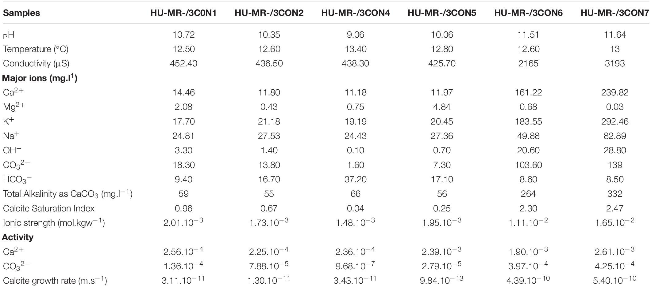
Table 1. Hydrochemistry dataset of the samples including pH, temperature, major ion concentrations, total alkalinity, calcite saturation index, ionic strength, activity and calcite growth rate from the research works of Mayes et al. (2008), Hull et al. (2014), Riley and Mayes (2015), Hobson et al. (2018), and Mayes et al. (2018).
Precipitation of carbonate material occurs immediately when the water contacts air, and waters seeping from the landfill package precipitate calcite rafts in shallow pools and slow moving water on emergence (Figure 2). The meniscus layer mineralization is a direct consequence of CO2 in-gassing, but extends for only a few meters downstream. Precipitation is greatest in the environment of waterfalls (Figure 2). Fine micrite sediments fill the upper pools within the Howden Burn waterfall-pool system (Figure 2). Dark patches on the waterfall surface indicates the presence of substantial diatomaceous biofilms, and a less common yellow discoloration reflects the occurrence of cyanobacteria.
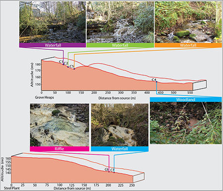
Figure 2. Geomorphological profile of the downstream transects of Howden Burn and Dene Burn with the localization of the riffle, waterfall, and woodland.
There is a significant hydrochemical gradient between the Dene Burn and Howden Burn streams (Table 1). Parameters such as pH, conductivity, alkalinity, CSI and R ([pH = 11.5–11.6]; [conductivity = 2160–3190 μS]; [alkalinity = 260–330mg.L–1]; [CSI = 2.3–2.5]; [R = 4.10–10 – 5.10–10m.s−1]) are dramatically more elevated in Howden Burn than in Dene Burn ([pH = 9–10.7]; [conductivity = 425–450 μS]; [alkalinity = 55–66 mg.L–1]; [CSI = 0.04–1]; [R = 9.10–13 – 3.10–11m.s−1]) (Table 1).
Location C4 in Dene Burn describes the lowest CSI (0.04), then followed by location C5 (0.25), C2 (0.67), and C1 respectively (0.96) (Table 1). In Howden Burn, the values are almost doubled at the C6 (2.3) and C7 (2.5) sites (Table 1) which are correlated with higher concentrations of carbonate (100–140 mg.L–1) and calcium (160–240 mg.L–1) (Table 1).
R is the lowest at location C5 (9.10–13m.s−1), then increases quite progressively at locations C2 (1.10–11m.s−1), C1 (3,1.10–11m.s−1), and C4 (3,4.10–11m.s−1) (Table 1). In Howden burn, R faces a major augmentation (C6: R = 4.10–10m.s-1; C7: R = 5.10–10m.s−1) (Table 1).
Calcite saturation index (CSI), ionic strength and activity of Ca2+ and CO32– ions were obtained by using the PHREEQC Interactive software. The calcite growth rate (R) was calculated following the formula established by Wolthers et al. (2012):
where I is the ionic strength, raq = {Ca2+}/{CO32–} activity ratio, S is the saturation ratio (Ω1/2) and R is expressed in m s–1. Growth rate differs from saturation index in that it predicts how quickly crystals will actually assemble, rather than how thermodynamically “favored” that assembly is. Consequently, this value is intrinsically much more closely linked to crystal assembly controls than saturation is. This parameter was indeed used previously for understanding the precipitation of terrestrial carbonates (Kandianis et al., 2008).
Mineralogy
X-ray powder diffraction (XRD) data were collected from ground sample (HU-MR-/3CON6) mounted in stainless steel sample holders. Data collection range 5 ≤ 2θ/° ≤ 80 with a step size 0.0262606° and a counting time of 304.725 s per step. Raw data were examined using the program PANAlytical HighScore (Plus) which is an implementation of the PDF2 database. This sample was also analyzed by Fourier transform infrared (FTIR) spectroscopy using an Agilent 4300 Handheld Portable FTIR and the peaks were analyzed and identified by the MicroLab FTIR Agilent Software.
Petrography and Terminology
Thin-sections (6 × 3 cm) were made for each sample, impregnated with blue-epoxy and were studied with a GXM-MXP Series L3230 optical microscope at the School of Environmental Sciences (University of Hull, England, United Kingdom) to determine the mineralogy, texture and the fabric of the studied carbonates. To identify the micro-texture and the micro-scale fabrics, a Scanning Electron Microscope (Zeiss EVO 60) attached to an EDS detector (Oxford Instruments INCA System350 with Silicon Drift Detector) was also used on the same samples for the characterization of their growth and diagenetic processes. The terminology used for petrographic descriptions follow the nomenclature from Pedley (1992), Jones et al. (2005), and Flügel (2013). The definitions of Jones (2017) for single crystal and polycrystal are also employed in this study. Single crystal corresponds to a solid object with only one grain or crystal and hence, no grain boundaries in which an orderly three-dimensional arrangement of the atoms, ions, or molecules is repeated throughout the entire volume. A polycrystal is an aggregate of several crystals or grains where the boundary between the grain is the grain boundary across which the orientation of the crystal changes and the point at which three boundaries meet is called the triple junction.
A key element of the petrographic part of this study is the definition of “shrubby.” We use the definition of Chafetz and Folk (1984): “three-dimensional, arborescent structures composed of CaCO3 that expand away from the substrate.” This differs from dendrites, for which we use the definition of Jones et al. (2005): “100–200 nm thick calcite fibers that form 3D lattice-like domains and in each dendrite domain, fibers have three structurally equal orientations.”
Results
Mineralogy
XRD data show that HU-MR-/3CON6 is highly crystalline and corresponds to pure calcite (Figure 3). However, FTIR measurements indicate a material which is not calcite via 3 significant peaks (λ = 600 cm–1; λ = 850 cm–1; λ = 1100 cm–1) (Figure 4). These absorptions are consistent with the presence of silica (SiO stretching in silica network defects, symmetric stretching of Si-O-Si bonds and silicon–oxygen covalent bonds vibrations respectively; Al-Oweini and El-Rassy, 2009). The absence of crystalline silica scattering in the XRD patterns indicate that this material must be amorphous, and is present in most samples at >1% concentrations. Consistent with field observations, SEM investigation indicated the presence of a large number of diatom frustules on the sample surface and within the shallow subsurface. The presence of substantial concentrations of these within the limestones explains the persistent presence of amorphous silica in these samples, indicating that the presence of diatomaceous biofilms at these sites during precipitation is persistent.
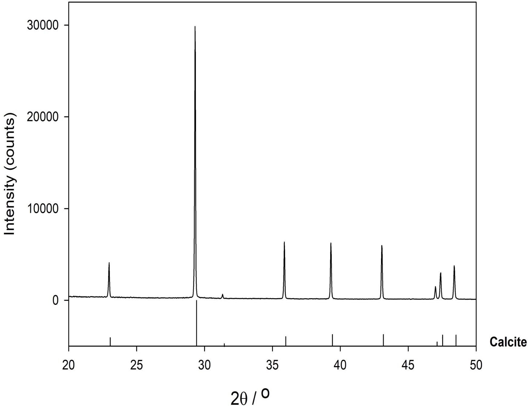
Figure 3. XRD pattern of the sample HU-MR-/3CON6.
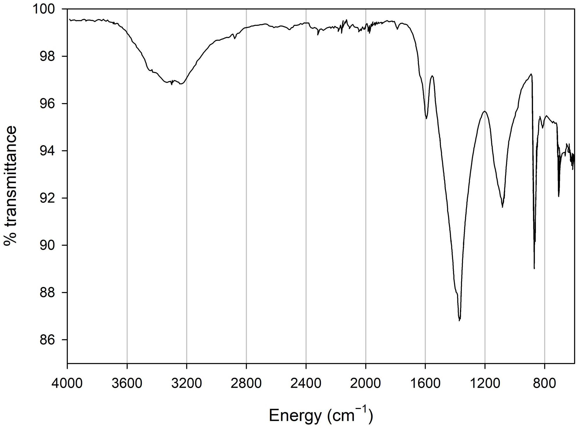
Figure 4. FTIR spectra of the sample HU-MR-/3CON6.
Macroscopic Description
All samples are light brown limestone with clear sedimentary structures corresponding to brown-dark laminations except the HU-MR-/3CON6 sample which is light beige exhibiting a circular ring structure with beige brown laminations (Figure 5). In the latter, the beige layers have a fibrous texture (Figure 5). This specimen developed as a stalactite growing on the surface of an annual grass and hanging from the roof at the mouth of the drainage tunnel emerging near the top of Howden Burn. The ∼8 mm of growth of this specimen have therefore occurred within a few months before sampling, and the rate of accumulation at this site is likely >>1 cm yr–1.
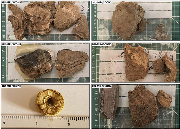
Figure 5. Macroscopic images of the Consett freshwater samples HU-MR-/3CON1, HU-MR-/3CON2, HU-MR-/3CON4, HU-MR-/3CON5, HU-MR-/3CON6, HU-MR-/3CON7.
Facies Descriptions
Eight types of microfacies have been identified on the basis of fabric, mineralogy and texture (Figure 6). We present a small number of replicates (6), which limits our ability to draw widely applicable conclusions about the distribution of specific features within the sediment. However, they present a wide range of microfabrics, some of which are rarely observed growing in natural environments today. We therefore limit our analysis to identification of these rare features, and to providing a framework for future investigations.
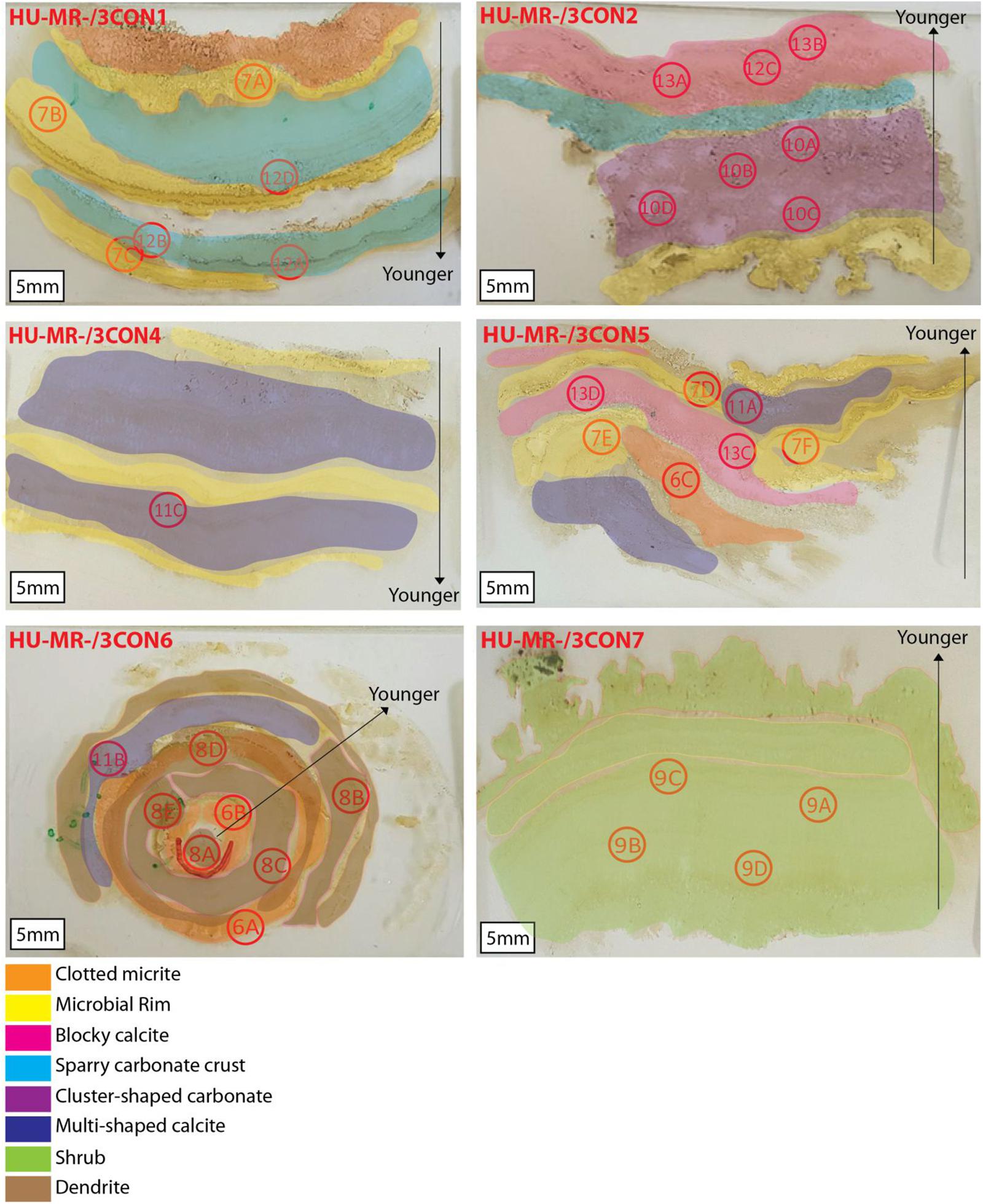
Figure 6. Thin sections from the Consett freshwater samples HU-MR-/3CON1, HU-MR-/3CON2, HU-MR-/3CON4, HU-MR-/3CON5, HU-MR-/3CON6, HU-MR-/3CON7 with the locations of the optical microscope images where the locations are respectively designed by the number of the figure from this manuscript followed by the letter corresponding to the subsection in the figure.
Facies 1: Clotted Micrite
Clotted micrite is made up of a brown micritic matrix composed of fine homogeneous rounded micrite peloids (Figures 7A–C). Individual micrite grains reach up to 7 μm in diameter and show (Figure 7D) prismatic tetrahedron-like (70 μm in diameter), and double-terminating calcite crystal morphologies with abundant twinned faces (100 μm in diameter) (Figure 7D). Diatoms are common components within this facies (Figures 7D–L) (20 μm in diameter) showing elongated and oval external morphologies [Gomphonema parvulum (Figure 7E), Gyrosigma acuminatum (Figure 7G), Navicula lanceolata (Figure 7H), Navicula gregaria (Figure 7I), Navicula gregaria (Figure 7J), Nitzschia amphibia (Figure 7K), Planothidium lanceolatum (Figure 7K), Sellaphora nigri (Figure 7L)]. Micrite shows a clotted distribution (Figures 7A–C) hosting intercrystalline porosity with cavities between 10–500 μm in diameter (Figures 7A–C).
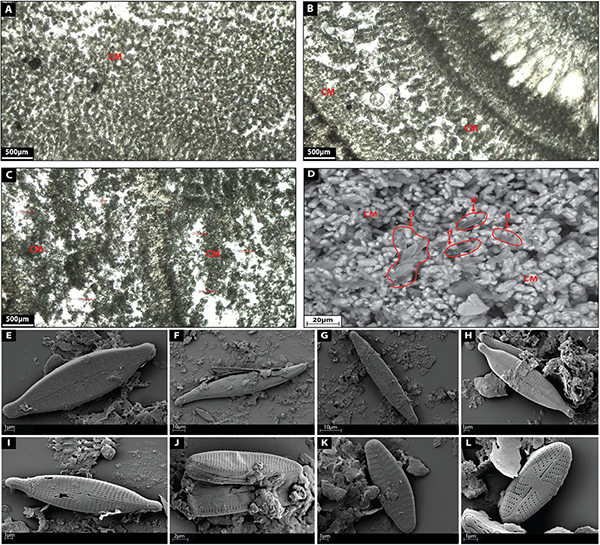
Figure 7. (A–C) Depict the microfacies images by petrographic microscope of clotted micrite (CM) facies. (D) Shows a SEM image of clotted micrite facies with diatoms (d). (E) Shows a SEM image of the diatom Gomphonema parvulum. (F) Shows a SEM image of the diatom Gyrosigma acuminatum. (G) Shows a SEM image of the diatom Navicula lanceolate. (H) Shows a SEM image of the diatom Navicula gregaria. (I) Shows a SEM image of the diatom Navicula gregaria. (J) Shows a SEM image of the diatom Nitzschia amphibian. (K) Shows a SEM image of the diatom Planothidium lanceolatum. (L) Shows a SEM image of the diatom Sellaphora nigri.
Pedley (1992) described a similar microfacies in freshwater “phytoherm” reef environments where clotted micrite was characterized by anhedral crystals approximately a few micrometers across on average.
Facies 2: Microbial Rim
This facies corresponds to thin black layers (180–250 μm thick) of dense micrite characterized by the presence of a diversity of microbial remains such as biodegraded biofilm or leaf material (Figures 8A–F).
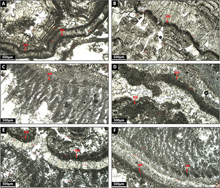
Figure 8. (A–F) Depict the microfacies images by petrographic microscope of microbial rim (MR) facies.
Facies 3: Dendrite
Dendrites are constituted by light gray calcite crystals growing radially forming flower-like geometries (Figures 9A–E) and are made up of radially elongated, polycrystalline calcite giving rise to V-shaped fans that grow upon a surface front. Fans average 580 microns in length and 120 microns in width. Some fans are tightly laterally packed which constraints the growth of the fans themselves. When more space is available for crystals to grow, fans develop preferably in one single direction producing feather-like crystal morphologies (Figures 9B–E).
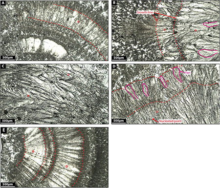
Figure 9. (A–E) Depict the microfacies images by petrographic microscope of dendrite facies (D).
Similar fabrics were described by Jones et al. (2005) in calcite travertine environments. They defined them as three-dimensional bushes, up to 1 cm high and 1 cm in diameter, with branches that radiate outward and upward from the main branch. Given the relatively loose crystal network, dendrites have high internal porosity (see Jones et al., 2005).
Facies 4: Calcite Shrub
Calcite shrubs are made up of light gray-green botryoidal-like crystal fans 1–1.5 mm in height and stacked each other as inverted cones growing on top of discontinuous horizons (Figures 10A–D). Botryoids are internally composed of very coarse sub to euhedral, elongated rhombohedral crystals forming bladed aggregates (60 μm in length) (Figures 10A–D) with their c-axis radiating from a previous substrate (Figures 10A–D). In places, the shrubs are surrounded by diatoms (Figures 10E–M) and bacterial filaments where bacterial filaments (25–60 μm in diameter) are quite rectilinear forming circular tubes (Figure 10E). Bladed crystal aggregates tend to develop a high intercrystalline microporosity (Figure 10E). The SEM confirms the bladed aggregation/imbrication of rhombohedral polycrystals (Figure 10E).
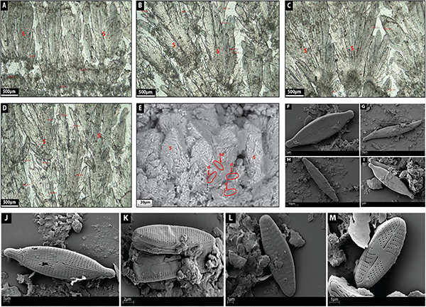
Figure 10. (A–D) depict the microfacies images by petrographic microscope of shrub (S) facies. (E) Shows a SEM image of shrub facies with diatoms (d) and bacterial filament (bf). (F) Shows a SEM image of the diatom Gomphonema parvulum. (G) Shows a SEM image of the diatom Gyrosigma acuminatum. (H) Shows a SEM image of the diatom Navicula lanceolate. (I) Shows a SEM image of the diatom Navicula gregaria. (J) Shows a SEM image of the diatom Navicula gregaria. (K) Shows a SEM image of the diatom Nitzschia amphibian. (L) Shows a SEM image of the diatom Planothidium lanceolatum. (M) Shows a SEM image of the diatom Sellaphora nigri.
Saller et al. (2016) described Pre-Salt calcite shrubs as radiating bundles of fibrous-to-prismatic crystals. Within a shrub branch, upward oriented bundles of radiating crystals have clear growth interference; however, the fibrous, upward-oriented bundles abruptly finish at the edge of a branch, leaving open vugs between shrubby growths (Saller et al., 2016). The shrubs seem to have grown upward and create positive relief (Saller et al., 2016).
Facies 5: Cluster-Shaped Carbonate
Cluster-shaped carbonates are here referred as translucent white calcite crystals ranging from 20 to 500 μm in height (Figures 11A–F). They form a matrix made up of coarse euhedral tetrahedron-like and double terminating calcite crystals with many cluster faces, which are surrounded by a black organic substance of biograded biofilm. Cluster-shaped carbonates display an extremely high intercrystalline porosity.
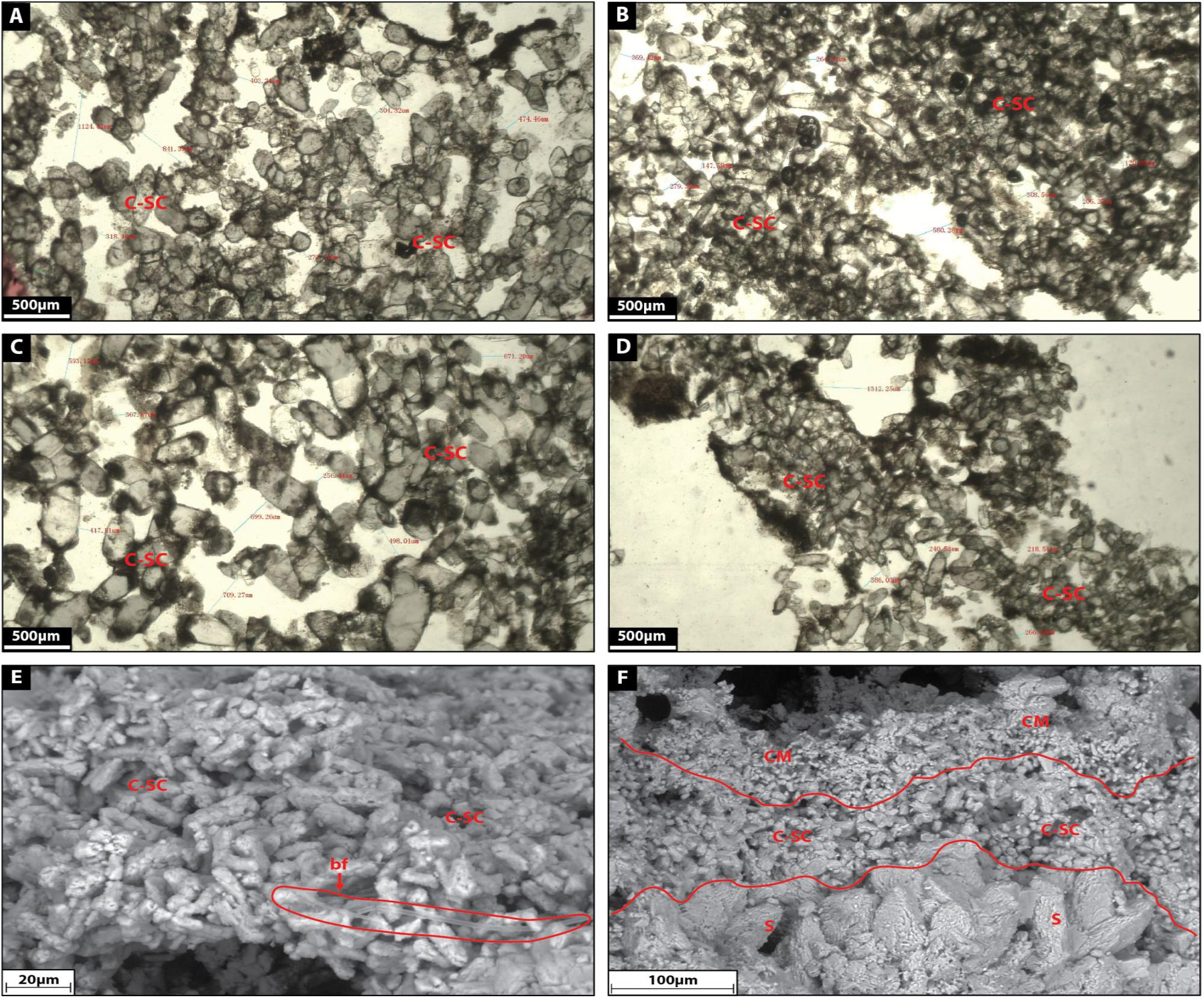
Figure 11. (A–D) Show the microfacies images by petrographic microscope of cluster-shaped carbonate (C-SC) facies. (E) Shows a SEM image of cluster-shaped carbonate facies with bacterial filament (bf). (F) Shows a SEM image of the transition between shrub, cluster-shaped carbonate and clotted micrite.
Facies 6: Multi-Shaped Calcite
Multi-shaped calcite corresponds to translucent white delicate calcite crystals (100–550 μm in diameter) displaying rounded external morphologies and a grain-to-grain contact arrangement (Figures 12A–C). Calcite crystals also exhibit trigonal, arrow and heart-shaped external morphologies (Figures 12A–C) and these crystals seem to correspond to coarse-grained carbonate slightly reworked and stacked together (Figures 12A–C). A black organic substance surrounds some crystals, which appear to be leaf material (Figures 12A–C) and there is a curved surface below grains (Figures 12A–C) as well as space between crystals displaying porosity (Figures 12A–C).
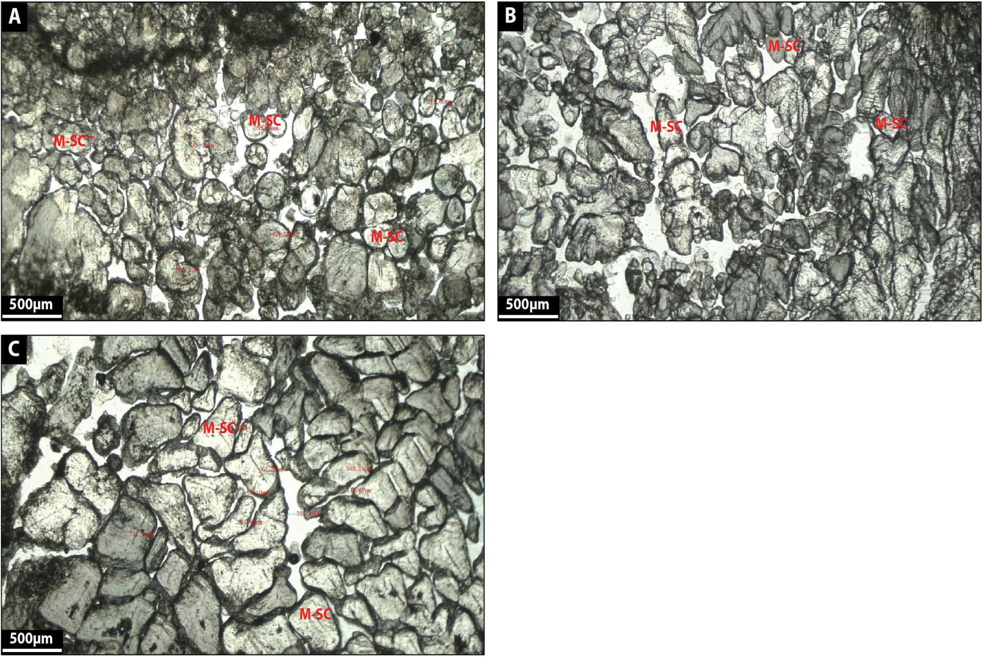
Figure 12. (A–C) show the microfacies images by petrographic microscope of multi-shaped calcite (M-SC) facies.
Facies 7: Sparry Carbonate Crust
Sparry carbonate crust comprises thick sparite crusts (500–2500 mm thick) made up of milky white to gray calcite (Figures 13A–E). The crystals show a very coarse, subhedral morphology as they partly developed crystal faces (Figures 13A–D). Some crystals are covered by black organic remains corresponding certainly to degraded biofilm (Figures 13B,C). Given the nature of these crystals, they develop very low intercrystalline porosity. Some crusts display several growth zones (Figure 13A) and exhibit botryoidal shapes (Figures 13A–C).
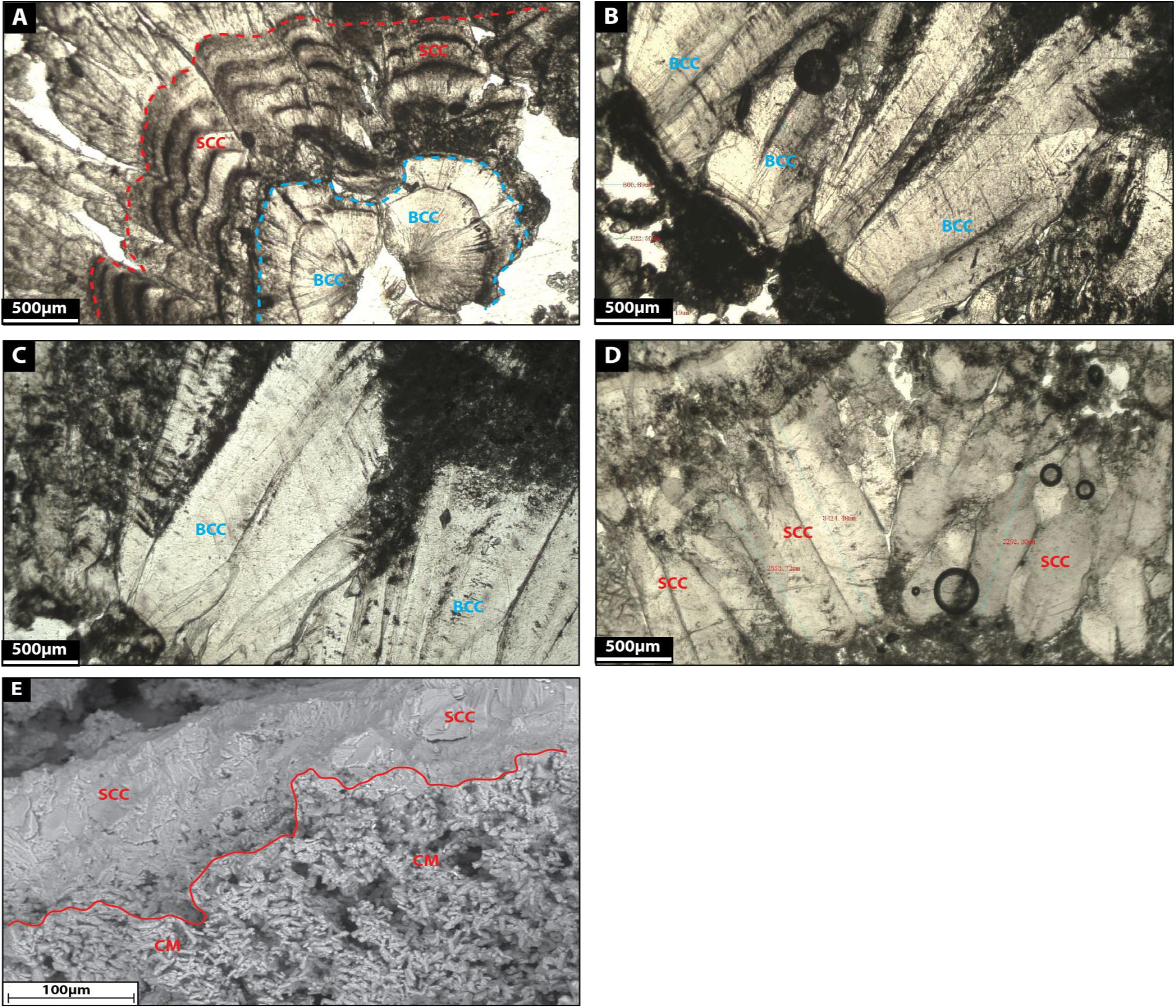
Figure 13. (A–D): Microfacies images by petrographic microscope of sparry carbonate crust (SCC) and bothryoidal carbonate crust facies (BCC). (E) Shows a SEM image of the transition between clotted micrite and sparry carbonate crust facies.
Facies 8: Blocky Calcite
Blocky calcite corresponds to single, very large crystals of calcite (500–1500 μm in diameter), where the crystals are milky white to translucent gray (Figures 14A–D). Coarse-grained euhedral crystals (Figures 14A–D) compose the calcite and the crystals show distinct crystal boundaries (Figures 14A–D).
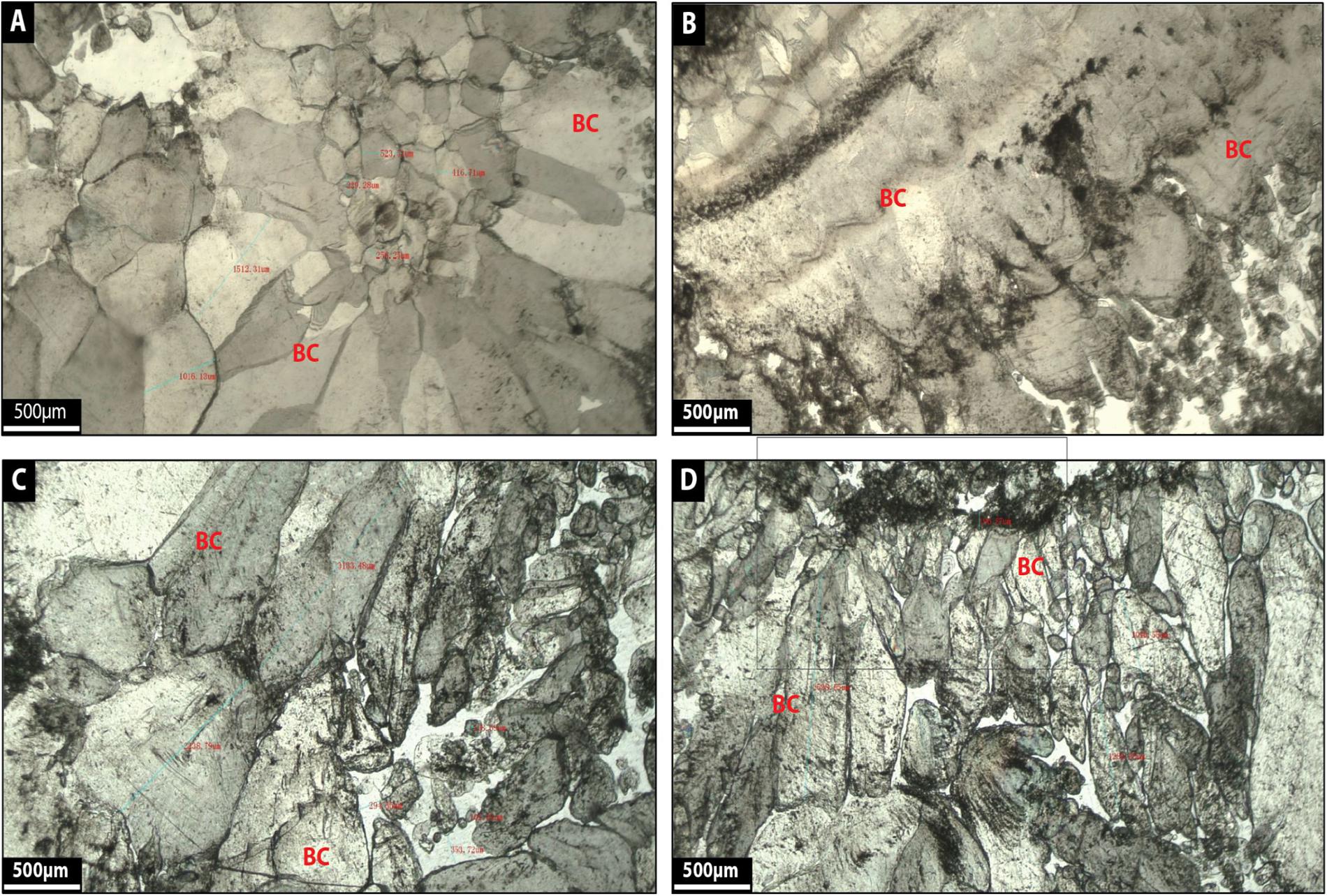
Figure 14. (A–D): Microfacies images by petrographic microscope of blocky calcite facies (BC).
Distribution of Microfacies
Shrubs occur exclusively at the most proximal location, C7, and is the only microfacies identified at that site (Figure 15A). Dendrite is the most common microfacies represented at location C6, but clotted micrite, sparry carbonate crust and cluster-shaped carbonate are present as well (Figure 15A). Microbial rim and sparry carbonate crust are the only microfacies described within location C1 (Figure 15A). Cluster-shaped carbonate is abundant at location C2 surrounded by some blocky calcite and sparry-carbonate crust (Figure 15A). Location C5 displays the most diverse microfacies, with clotted micrite, microbial rim, blocky calcite and multi-shaped calcite all contributing equal proportions of the sediment (Figure 15A). Multi-shaped calcite is a unique microfacies present only at location C4, and even these it is not abundant (Figure 15A).
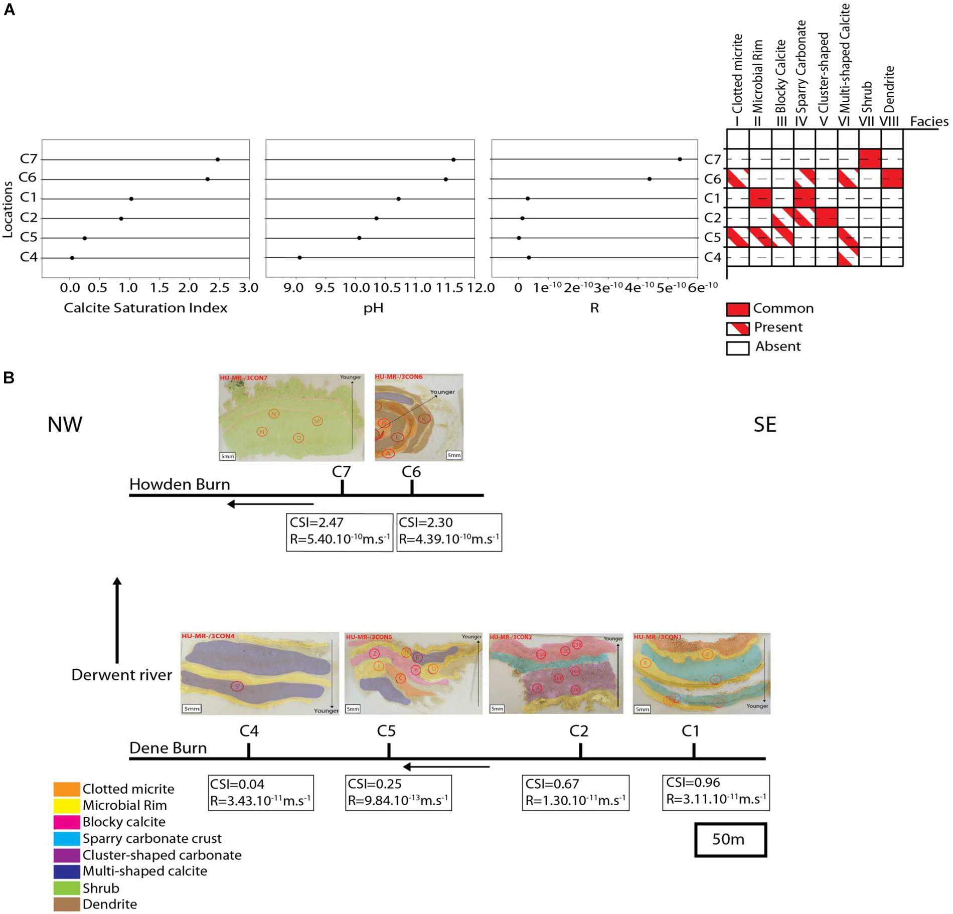
Figure 15. (A) depicts the sample locations versus Calcite Saturation Index, pH, calcite growth rate (R) and distribution of microfacies. (B) Shows the depositional model summarizing the lateral changes of the microfacies.
Discussion
Hydrochemistry Versus Distribution of Microfacies
In proximal Howden Burn, locations C6 and C7 show deposition principally of shrubby calcite (C7), and dendrite (C6) (pH = 11.5; CSI = 2.5; R = 5.10–10m.s−1) (Figure 15A). These sites are characterized by very high pH (11.5–11.6), calcium concentration (161–240 mg.L–1) and carbonate concentration (104–140 mg.L–1) (Table 1). Consequently, calcite saturation (CSI = 2.3–2.5) and calcite growth rate (R = 4.4.10–10–5.4.10–10m.s−1) are also very elevated (Figure 15A). As the solution moves away from the most proximal sites, calcium and alkalinity are consumed steadily reducing CSI. However, this near-linear change in saturation does not well reflect the disappearance of shrub and dendrite microfacies, which do not occur beyond C6. This better reflects R, which is 100–1000 times lower in more distal Dene Burn sites than in Howden Burn (10–12–3.10–13m.s–1) (Figure 15A). In locations C1 and C2, despite medium CSI (1–1.3) and high pH (10.3–10.7), R is low (1.10–11–3.10–11 m.s–1) (Figure 15A), and this relatively weak kinetic forcing corresponds to formation of microbial rim (C1), sparry-carbonate crust (C1) and cluster shaped carbonate (C2). The most distal sites exhibiting significant carbonate deposits (C4 and C5) exhibit the lowest CSI (0.04–0.25), R (3.10–11–1.10–12) and pH (9–10.3) and are dominated by multi-shaped calcite (C4-C5), clotted micrite (C5), and blocky calcite (C5).
Kinetic Control on Shrubby and Dendritic Carbonate
The juxtaposition of the hydrochemistry and distribution of microfacies shows that shrubby and dendritic crystals develop with high kinetic forcing, blocky calcite at low kinetic forcing and classic “microbialite” rim and clotted micrite forming at moderate-low forcing. We therefore conclude that formation of these microfacies in this system exhibits a kinetic rather than thermodynamic control. This is highly comparable with findings from materials chemistry summarized by Meldrum and Cölfen (2008). Kinetic control of crystallization arises from enhanced nucleation onto kinetically favored crystal faces and step-edges Ostwald’s step rule. Skeletal biomineral morphologies will self-assemble in such a setting due to Berg effect, where supersaturation over a flat face is low at the center and high near the edges, causing first “hopper like” then true single-crystalline ordered dendrites, disordered polycrystalline side branches, and finally disordered polycrystalline dendrites and dense branching morphologies as the kinetic forcing becomes more extreme. Sunagawa (1999) shows that it is a general rule that growth rate anisotropy will determine the forms of polyhedral crystal, as seen in the development of snow crystals (Libbrecht, 2012), where solid hexagonal plates crystallize at low supersaturation, whereas increasing the supersaturation leads to dendritic growth and flower-like morphologies with six petals. Beck and Andreassen (2012) report similar kinetic control on vaterite formation, where low levels of supersaturation lead to the growth of hexagonal, plate-like crystals while increasing kinetic forcing force causes a shift of the particle growth mechanisms toward dendritic growth.
Formation Processes of Microfacies
Where kinetic forcing is reduced (lower R), diffusive controls on crystal formation re-assert themselves and non-dendritic fabrics occur (blocky calcite which displays a polyhedral shape in a single crystal). This is as would be expected from fundamental crystal assembly controls at relatively low rates of supersaturations (Meldrum and Cölfen, 2008). Curiously, we find the minimum of biofilm and microbe presence within these fabrics, indicating a process of formation dominated by inorganic mineralization, as defined by Dupraz et al. (2009). Classic “microbialite” fabrics (microbial rim and clotted micrite) occur within the middle and low saturation regime. Diatom and cyanobacterial biofilms are preserved directly as thin brown bands recognized on the thin-section material (Figure 6), and indirectly within the biologically influenced microfacies where the carbonate precipitation is indirectly modified by a precursor organomineral (Dupraz et al., 2009). It is also important to note that the diatoms reported generally develop in environmental conditions of freshwaters and represent biotopes of low to (at most) moderate electrolyte content (Sterrenburg, 1995; Van de Vijver et al., 2013). There were found living epilithically in several smaller rivers and brooks with an almost slightly alkaline pH (7.5) and low specific conductance levels (75–100 μS.cm–1) (Sterrenburg, 1995; Van de Vijver et al., 2013). In our study, it is therefore surprising to find this abundance of diatoms in such very salty and alkaline conditions.
Cluster-shaped carbonate was developed among bacterial filaments with an organic film forming sticky thin black layer around crystals (Figures 11A–D) which could correspond to EPS. These organic components associated with the micritic matrix of this facies along with its chemical characteristics (high alkalinity, medium pH and SI) suggest that they come from biologically influenced mineralization as well. The distribution of bio-influenced facies is not ordered with respect to the single-crystal inorganic precipitates, but rather both types of precipitation occur apparently randomly.
Kinetic forcing of dendrite growth can be enhanced by “poisoning” of some step-edges by additive molecules, particularly polymerized, polar organic molecules (Meldrum and Cölfen, 2008). We noted that biofilms were common even in proximal sites within Howden and Dene Burns during sampling, and both diatom frustules and organic carbon is pervasive through the majority of samples. Consequently, it is possible that organic additives are promoting the formation of extreme skeletal crystals in these systems at relatively low R. Whether skeletal crystals would form spontaneously in the absence of biofilm EPS was not possible to test during this study. However, we were able to demonstrate that within shrubby fabrics, no indication of microbial biofilm presence (i.e., classic microbialite features) could be identified, even when diatoms were touching the carbonate: it seems that if kinetic forcing is permitted by local hydrochemistry, all the carbonate product generated at that site will comprise skeletal composite crystals. Consequently, the absence of microbial textures does not appear to be a criterion for assuming no microbial influence on precipitation.
Co-existence of Fabrics Within a Same Site
The co-existence of different fabrics at a same location (e.g., at C1, C2, C5, and C6 sites) indicates that the rather “static” analysis we present above is oversimplified, and that some spatial or temporal structure in the environment is present to cause physical association of the mineral products. This will be at least in part due to a variable chemistry caused by weather fluctuations (rainy, dry, low or high temperatures according to season) (Riley and Mayes, 2015) (Figure 15A). Mayes et al. (2008) showed that the hydrochemical system in Howden Burn and Dene Burn is relatively stable with a very elevated pH (pH = 11–12) over the 36-year data series but when heavy rainfall occurs, the river does adapt very rapidly. Spate flow changes the hydraulics of the flow altering gas exchange, (Gomes et al., 2017), reduces carbonate and calcium concentration and pH, and therefore suppressed CSI and R (Riley and Mayes, 2015). As reduced R will suppress kinetically forced fabrics and promote diffusion-forced crystal formation, this process alone will explain co-occurrence at any given site. For example, in the case of C6, short phases of reduced R and CSI may produce brief hiatuses in growth, forcing creation of concentric rings of dendritic fabrics (Figure 6). In addition to this abiotic forcing, it is likely that the distribution of biofilms is not spatially smooth, and patchy bio-influence will result in patchy occurrence of bio-influenced microfabrics. The apparently random co-occurrence of diffusion-forced and bio-influenced fabrics in Dene Burn likely reflects this spatial complexity within the sites microbiology.
Depositional Model
Although we acknowledge the relatively small sample size in this case and the need for further investigation of such systems, given the hydrogeochemical and facies variation at the site a depositional model can be forwarded. This model is based on the key interpretation that lateral distribution of microfacies at the site relates to geochemical forcing (Figures 15A,B). Shrub and dendrite microfacies disappear with distance from the source, where CSI and R are excessively high (Figure 15B). In the most distal part of the river, microbial rim are quite continuous, occurring in most sites (Figure 15B). Cluster-shaped carbonate is the only facies represented upstream (C2) and sparry carbonate crust co-appear in C1 and C2 locations (Figure 15B). Blocky calcite and multi-shaped calcite are present in the downstream part of Dene Burn (C4 and C5) (Figure 15B). Clotted micrite is exclusively represented in both proximal and distal zones of the river (C1, C5, C6) (Figure 15B).
Sedimentology in the Anthropocene
Although this is the first systematic analysis of the sedimentology of an Anthropocene limestone, the Consett site is not unique, and similar hyperalkaline sites occur in most post-industrial landscapes. These extremely alkaline environments have been found for instance in man-made river bed after repository building measures in Austria (Boch et al., 2015), slag-fill aquifers in the Lake Calumet region of Chicago (Roadcap et al., 2005, 2006), and Coatham Marsh steel slag leachate discharges in United Kingdom (Mayes et al., 2008). Examples such as non-ferrous metal industry waste disposal sites in Slovakia (Pristas et al., 2015), and technosol contaminated by former mining activity in Slovak Republic (Šimonovièová et al., 2017) can be cited as well. Understanding their operation in terms of mass deposition is a key part of fully constraining their behavior, and thus being able to manage them successfully. In particular, our finding that precipitation in proximal parts of the system are not diffusion-controlled is likely to result in deviation of element distribution coefficients from empirical values, and higher incorporation of trace metals and metalloids is anticipated in these sites. We recommend that further sedimentological investigation of these “accidental laboratories” is likely to yield further insights, of use both to geoscientists and environmental scientists working with very different scientific motivations.
Comparing Natural, Alkaline Saline Lakes With Anthropogenic Hyperalkaline Occurrences
A striking feature of recent saline alkaline lakes in rift tectonic settings (such as the East African Rift System, EARS) is the strong dissimilarity between alkaline metal concentration (calcium and magnesium) and the alkalinity of the waters (measured as carbonate and bicarbonate contents). During the evolution of these saline lakes, they tend to become Ca and Mg-poor systems due to the combined effects of the evaporative concentration and the relative mineral solubility which triggers the sequential precipitation of minerals from carbonates to silicates to complex salts (Eugster and Hardie, 1978; Deocampo and Renaut, 2016).
Many recent EARS lakes (e.g., Lake Magadi or Lake Bogoria; Jones et al., 1977; Renaut et al., 2002) have been considered tectonically and hydrologically similar to the ancient Pre-Salt lakes. However, they do not show clear evidence of substantial accumulation of spherulitic carbonate sediments, questioning whether EARS usual Ca and Mg-poor chemistries are encouraging spherulitic carbonate precipitation (Rogerson et al., 2017).
Furthermore, the record of anthropogenically mediated carbonate deposits such as those described here or in an asbestos open pit pond in Yukon, Canada (Power et al., 2011) is increasingly demonstrating that spherulitic carbonate growth can easily arise from waters anomalously enriched in calcium and magnesium, apart from elevated alkalinities and pH. In these sites, the alkalinity engine is thought to be related to the progressive atmospheric CO2 ingassing (Rogerson et al., 2017) or the dissolution of the carbonate bedrock (Power et al., 2011) rather than increasing evaporation as occurs in alkaline lakes (Eugster and Hardie, 1978).
In addition, both natural alkaline, saline lakes and industrial hyperalkaline ponds are known to precipitate primary aragonite and/or low-Mg calcite minerals. This is mainly driven by the Mg/Ca ratios and the supersaturation state of the precipitating waters (De Choudens-Sánchez and González, 2009; Wang et al., 2012). An interesting observation from the Pre-Salt Aptian carbonate record is the repeated occurrence of Mg-rich and Sr-rich calcites (Saller et al., 2016) which are thought to be primary fabrics due to the lack of an original aragonite precursor. Also, shrubs described in the Kwanza upper case B were interpreted as originally precipitated as Mg-rich calcites and lately transformed to low-Mg calcites (Saller et al., 2016). These features strongly suggest that the Pre-Salt lake waters were likely much richer in Mg and sustained higher supersaturation states than those recorded in both the recent EARS and man-made alkaline counterparts. Thus, a major future challenge is to constrain the hydrological conditions enabling natural alkaline, saline waterbodies to chemically behave, at least in part, as anthropogenic spherulite-producing sites (Mercedes-Martín et al., 2019).
Conclusion
A sedimentological, mineralogical and geochemical study was conducted in human-induced carbonate deposits (Consett) including analysis of microfacies (petrographic microscope and SEM), XRD, FTIR analysis and hydrogeochemistry to shed light on the physico-chemical processes forming the analogous Pre-Salt Aptian non-skeletal carbonates. Although the carbonates at Consett arise from low temperature and highly alkaline steel lag leachates, they exhibit strikingly similar primary crystal morphologies to those recognized in the Pre-Salt shrub carbonates. The Consett carbonates developed in a spring waterfall environment in the vicinity of former steelworks and under the influence of constant supplies of calcium and carbonate ions. The shrubby carbonate facies at the site appear to be the result of extreme environmental conditions (elevated pH and alkalinity, high CSI and R) but shrubby and dendritic crystals attest of a kinetic rather than thermodynamic control with high kinetic forcing. Non-dendritic facies (blocky calcite, sparry-carbonate crust and cluster-shaped carbonate) result from a low kinetic forcing and classic “microbialite” rim and clotted micrite form at a moderate-low forcing. Similar hyperalkaline sites, such as the study case of Consett, occur in most post-industrial landscapes. Understanding their operation in terms of mass deposition is a key part of fully constraining their behavior, and thus being able to manage them successfully.
Data Availability
All datasets generated for this study are included in the manuscript and/or the supplementary files.
Author Contributions
The idea for this manuscript arose from the discussions between all authors. LB executed the petrographic analysis and drafted the manuscript. MR made improvements through the whole manuscript. RM-M provided insight on the facies descriptions and the discussion. TP provided the data of XRD pattern and the FTIR spectra. WM contributed to the hydrochemical data and their interpretation. EC identified the different taxonomies of diatoms.
Funding
Support for this work came from the University of Hull.
Conflict of Interest Statement
RM-M was employed by company SZALAI Grup.
The remaining authors declare that the research was conducted in the absence of any commercial or financial relationships that could be construed as a potential conflict of interest.
Acknowledgments
We would like to thank Mark Anderson for the production of thin sections. Kim Rosewell is acknowledged for the supply of material during the field campaigns. We would like to express our gratitude to Edgley Cesar for his contribution to this manuscript. This manuscript greatly benefited from the remarks of the two reviewers.
References
Al-Oweini, R., and El-Rassy, H. (2009). Synthesis and characterization by FTIR spectroscopy of silica aerogels prepared using several Si(OR)4 and R′′Si(OR′)3 precursors. J. Mol. Struct. 919, 140–145. doi: 10.1016/j.molstruc.2008.08.025
Andrews, J. E., Riding, R., and Dennis, P. F. (1997). The stable isotope record of environmental and climatic signals in modern terrestrial microbial carbonates from Europe. Palaeogeogr. Palaeoclimatol. Palaeoecol. 129, 171–189. doi: 10.1016/s0031-0182(96)00120-4
Beck, R., and Andreassen, J. P. (2012). The influence of crystallization conditions on the onset of dendritic growth of calcium carbonate. Cryst. Res. Technol. 47, 404–408. doi: 10.1002/crat.201100599
Boch, R., Dietzel, M., Reichl, P., Leis, A., Baldermann, A., Mittermayr, F., et al. (2015). Rapid ikaite (CaCO3⋅ 6H2O) crystallization in a man-made river bed: hydrogeochemical monitoring of a rarely documented mineral formation. Appl. Geochem. 63, 366–379.
Ceraldi, T. S., and Green, D. (2016). Evolution of the South Atlantic lacustrine deposits in response to Early Cretaceous rifting, subsidence and lake hydrology. Geol. Soc. Lond. Spec. Publications 438, S438–S510.
Chafetz, H. S., and Butler, J. C. (1980). Petrology of recent caliche pisolites, spherulites, and speleothem deposits from central Texas. Sedimentology 27, 497–518. doi: 10.1111/j.1365-3091.1980.tb01644.x
Chafetz, H. S., and Folk, R. L. (1984). Travertines; depositional morphology and the bacterially constructed constituents. J. Sediment. Res. 54, 289–316.
De Choudens-Sánchez, V., and González, L. A. (2009). Calcite and aragonite precipitation under controlled instantaneous supersaturation: elucidating the role of CaCO3 saturation state and Mg/Ca ratio on calcium carbonate polymorphism. J. Sediment. Res. 79, 363–376. doi: 10.2110/jsr.2009.043
Deocampo, D. M., and Renaut, R. W. (2016). “Geochemistry of African soda lakes,” in Soda Lakes of East Africa, ed. M. Schagerl (Cham: Springer), 77–93. doi: 10.1007/978-3-319-28622-8_4
Dupraz, C., Reid, R. P., Braissant, O., Decho, A. W., Norman, R. S., and Visscher, P. T. (2009). Processes of carbonate precipitation in modern microbial mats. Earth Sci. Rev. 96, 141–162. doi: 10.1016/j.earscirev.2008.10.005
Flügel, E. (2013). Microfacies of Carbonate Rocks: Analysis, Interpretation and Application. Berlin: Springer Science and Business Media.
Ford, T. D., and Pedley, H. M. (1996). A review of tufa and travertine deposits of the world. Earth Sci. Rev. 41, 117–175. doi: 10.1016/s0012-8252(96)00030-x
Fouke, B. W., Farmer, J. D., Des Marais, D. J., Pratt, L., Sturchio, N. C., Burns, P. C., et al. (2000). Depositional facies and aqueous-solid geochemistry of travertine-depositing hot springs (Angel Terrace, Mammoth Hot Springs, Yellowstone National Park, USA). J. Sediment. Res. 70, 565–585. doi: 10.1306/2dc40929-0e47-11d7-8643000102c1865d
Gomes, H. I., Rogerson, M., Burke, I. T., Stewart, D. I., and Mayes, W. M. (2017). Hydraulic and biotic impacts on neutralisation of high-pH waters. Sci. Total Environ. 601, 1271–1279. doi: 10.1016/j.scitotenv.2017.05.248
Harber, A. J., and Forth, R. A. (2001). The contamination of former iron and steel works sites. Environ. Geol. 40, 324–330. doi: 10.1007/s002540000167
Hobson, A. J., Stewart, D. I., Bray, A. W., Mortimer, R. J., Mayes, W. M., Riley, A. L., et al. (2018). Behaviour and fate of vanadium during the aerobic neutralisation of hyperalkaline slag leachate. Sci. Total Environ. 643, 1191–1199. doi: 10.1016/j.scitotenv.2018.06.272
Hull, S. L., Oty, U. V., and Mayes, W. M. (2014). Rapid recovery of benthic invertebrates downstream of hyperalkaline steel slag discharges. Hydrobiologia 736, 83–97. doi: 10.1007/s10750-014-1894-5
Jones, B. (2017). Review of calcium carbonate polymorph precipitation in spring systems. Sediment. Geol. 353, 64–75. doi: 10.1016/j.sedgeo.2017.03.006
Jones, B., Renaut, R. W., Bernhart Owen, R., and Torfason, H. (2005). Growth patterns and implications of complex dendrites in calcite travertines from Lýsuhóll, Snaefellsnes, Iceland. Sedimentology 52, 1277–1301.
Jones, B. F., Eugster, H. P., and Rettig, S. L. (1977). Hydrochemistry of the lake Magadi basin, Kenya. Geochim. Cosmochim. Acta 41, 53–72. doi: 10.1016/0016-7037(77)90186-7
Kandianis, M. T., Fouke, B. W., Johnson, R. W., Veysey, J., and Inskeep, W. P. (2008). Microbial biomass: a catalyst for CaCO3 precipitation in advection-dominated transport regimes. Geol. Soc. Am. Bull. 120, 442–450. doi: 10.1130/b26188.1
Leleu, T., Chavagnac, V., Delacour, A., Noiriel, C., Ceuleneer, G., Aretz, M., et al. (2016). Travertines associated with hyperalkaline springs: evaluation as a proxy for paleoenvironmental conditions and sequestration of atmospheric CO2. J. Sediment. Res. 86, 1328–1343. doi: 10.2110/jsr.2016.79
Libbrecht, K. G. (2012). Toward a Comprehensive Model of Snow Crystal Growth Dynamics: 1. Overarching Features and Physical Origins. Available at: https://arxiv.org/pdf/1211.5555.pdf (accessed January, 2019).
Mayes, W. M., Riley, A. L., Gomes, H. I., Brabham, P., Hamlyn, J., Pullin, H., et al. (2018). Atmospheric CO2 sequestration in iron and steel slag: consett, county Durham, United Kingdom. Environ. Sci. Technol. 52, 7892–7900. doi: 10.1021/acs.est.8b01883
Mayes, W. M., Younger, P. L., and Aumônier, J. (2008). Hydrogeochemistry of alkaline steel slag leachates in the UK. Water Air Soil Pollut. 195, 35–50. doi: 10.1007/s11270-008-9725-9
Meldrum, F. C., and Coölfen, H. (2008). Controlling mineral morphologies and structures in biological and synthetic systems. Chem. Rev. 108, 4332–4432. doi: 10.1021/cr8002856
Mercedes-Martín, R., Ayora, C., Tritlla, J., and Sánchez-Román, M. (2019). The hydrochemical evolution of alkaline volcanic lakes: a model to understand the Cretaceous Presalt mineral assemblages. Earth Sci. Rev. (in press).
Mercedes-Martín, R., Brasier, A. T., Rogerson, M., Reijmer, J. J., Vonhof, H., and Pedley, M. (2017). A depositional model for spherulitic carbonates associated with alkaline, volcanic lakes. Mar. Pet. Geol. 86, 168–191. doi: 10.1016/j.marpetgeo.2017.05.032
Mercedes-Martín, R., Rogerson, M. R., Brasier, A. T., Vonhof, H. B., Prior, T. J., Fellows, S. M., et al. (2016). Growing spherulitic calcite grains in saline, hyperalkaline lakes: experimental evaluation of the effects of Mg-clays and organic acids. Sediment. Geol. 335, 93–102. doi: 10.1016/j.sedgeo.2016.02.008
Minissale, A., Evans, W. C., Magro, G., and Vaselli, O. (1997). Multiple source components in gas manifestations from north-central Italy. Chem. Geol. 142, 175–192. doi: 10.1016/s0009-2541(97)00081-8
Pedley, M. (1992). Freshwater (phytoherm) reefs: the role of biofilms and their bearing on marine reef cementation. Sediment. Geol. 79, 255–274. doi: 10.1016/0037-0738(92)90014-i
Power, I. M., Wilson, S. A., Dipple, G. M., and Southam, G. (2011). Modern carbonate microbialites from an asbestos open pit pond, Yukon, Canada. Geobiology 9, 180–195. doi: 10.1111/j.1472-4669.2010.00265.x
Pristas, P., Stramova, Z., Kvasnova, S., Judova, J., Perhoacova, Z., Vidova, B., et al. (2015). Non-ferrous metal industry waste disposal sites as a source of polyextremotolerant bacteria. Nova Biotechnol. Chim. 14, 62–68. doi: 10.1515/nbec-2015-0015
Renaut, R. W., Jones, B., Tiercelin, J. J., and Tarits, C. (2002). Sublacustrine precipitation of hydrothermal silica in rift lakes: evidence from Lake Baringo, central Kenya Rift Valley. Sediment. Geol. 148, 235–257. doi: 10.1016/s0037-0738(01)00220-2
Riley, A. L., and Mayes, W. M. (2015). Long-term evolution of highly alkaline steel slag drainage waters. Environ. Monit. Assess. 187:463. doi: 10.1007/s10661-015-4693-1
Roadcap, G. S., Kelly, W. R., and Bethke, C. M. (2005). Geochemistry of extremely alkaline (pH> 12) ground water in slag-fill aquifers. Groundwater 43, 806–816. doi: 10.1111/j.1745-6584.2005.00060.x
Roadcap, G. S., Sanford, R. A., Jin, Q., Pardinas, J. R., and Bethke, C. M. (2006). Extremely alkaline (pH> 12) ground water hosts diverse microbial community. Groundwater 44, 511–517. doi: 10.1111/j.1745-6584.2006.00199.x
Rogerson, M., Mercedes-Martín, R., Brasier, A. T., McGill, R. A., Prior, T. J., Vonhof, H., et al. (2017). Are spherulitic lacustrine carbonates an expression of large-scale mineral carbonation? A case study from the East Kirkton Limestone, Scotland. Gondwana Res. 48, 101–109. doi: 10.1016/j.gr.2017.04.007
Saller, A., Rushton, S., Buambua, L., Inman, K., McNeil, R., and Dickson, J. T. (2016). Pre-Salt stratigraphy and depositional systems in the Kwanza Basin, offshore Angola. AAPG Bull. 100, 1135–1164. doi: 10.1306/02111615216
Šimonovièová, A., Ferianc, P., Vojtková, H., Pangallo, D., Hanajík, P., Kraková, L., et al. (2017). Alkaline Technosol contaminated by former mining activity and its culturable autochthonous microbiota. Chemosphere 171, 89–96. doi: 10.1016/j.chemosphere.2016.11.131
Spadafora, A., Perri, E., McKenzie, J. A., and Vasconcelos, C. (2010). Microbial biomineralization processes forming modern Ca: Mg carbonate stromatolites. Sedimentology 57, 27–40. doi: 10.1111/j.1365-3091.2009.01083.x
Sterrenburg, F. A. S. (1995). Studies on the genera Gyrosigma and Pleurosigma (Bacillariophyceae): Gyrosigma acuminatum (Kützing) Rabenhorst, G. spenceri (Quekett) Griffith, and G. rautenbachiae Cholnoky. Proc. Acad. Nat. Sci. Philadelphia 146, 467–480.
Tosca, N. J., Tutolo, B., Wood, R., and Huwald, N. (2018). “Chemical Constraints on Carbonate Sedimentation and Fabric Development, Barra Velha Formation, Santos Basin, Brazil,” in Proceedings of the ACE 2018 Annual Convention and Exhibition, (Salt Lake City, UT: AAPG).
U.S. Geological Survey [USGS] (2014). Alkalinity Calculator. Available at: http://or.water.usgs.gov/alk/ (accessed January, 2019).
Van de Vijver, B., Wetzel, C., Kopalová, K., Zidarova, R., and Ector, L. (2013). Analysis of the type material of Achnanthidium lanceolatum Brébisson ex Kützing (Bacillariophyta) with the description of two new Planothidium species from the Antarctic Region. Fottea 13, 105–117. doi: 10.5507/fot.2013.010
Wang, D., Hamm, L. M., Giuffre, A. J., Echigo, T., Rimstidt, J. D., Yoreo, J. J., et al. (2012). Revisiting geochemical controls on patterns of carbonate deposition through the lens of multiple pathways to mineralization. Faraday Discuss. 159, 371–386. doi: 10.1039/c2fd20077e
Wolthers, M., Nehrke, G., Gustafsson, J. P., and Van Cappellen, P. (2012). Calcite growth kinetics: modeling the effect of solution stoichiometry. Geochim. Cosmochim. Acta 77, 121–134. doi: 10.1016/j.gca.2011.11.003
Wright, P., and Tosca, N. (2016). “A Geochemical Model for the Formation of the Pre-Salt Reservoirs, Santos Basin, Brazil: Implications for Understanding Reservoir Distribution,” in Proceedings of the AAPG-2016 Annual Convention and Exhibition, (Calgary, AB).
Keywords: Pre-Salt reservoirs, alkaline steel slag, Consett, shrubby carbonate, microbial, hydrochemistry, crystal growth, intercrystalline porosity
Citation: Bastianini L, Rogerson M, Mercedes-Martín R, Prior TJ, Cesar EA and Mayes WM (2019) What Causes Carbonates to Form “Shrubby” Morphologies? An Anthropocene Limestone Case Study. Front. Earth Sci. 7:236. doi: 10.3389/feart.2019.00236
Received: 13 March 2019; Accepted: 28 August 2019;
Published: 11 September 2019.
Edited by:
Michael Andrew Clare, University of Southampton, United KingdomReviewed by:
Anneleen Foubert, Université de Fribourg, SwitzerlandDavid Mark Hodgson, University of Leeds, United Kingdom
Copyright © 2019 Bastianini, Rogerson, Mercedes-Martín, Prior, Cesar and Mayes. This is an open-access article distributed under the terms of the Creative Commons Attribution License (CC BY). The use, distribution or reproduction in other forums is permitted, provided the original author(s) and the copyright owner(s) are credited and that the original publication in this journal is cited, in accordance with accepted academic practice. No use, distribution or reproduction is permitted which does not comply with these terms.
*Correspondence: Laura Bastianini, TC5CYXN0aWFuaW5pQGh1bGwuYWMudWs=