 Hongbo Wang1
 Lianglin Dong
 Qingsong Zhang
- 1College of Civil Engineering and Architecture, Shandong University of Science and Technology, Qingdao, China
- 2Geotechnical and Structural Engineering Research Center, Shandong University, Jinan, China
- 3School of Transportation and Civil Engineering, Shandong Jiaotong University, Jinan, China
- 4Qingdao West Coast Rail Transit Co., Ltd., Qingdao, China
Due to the hidden nature of the grouting project, it has not been possible to get a clear picture of the slurry transport law, and most of the existing permeation grouting theories have ignored the tortuous characteristics of the pore channels of porous media. Based on the fractal theory of porous media and the equation of seepage motion of viscous time-varying Bingham fluid, a theoretical model of permeation grouting with viscous time-varying Bingham fluid is established, and viscosity tests are carried out for C-S slurry to obtain the time-varying equation of viscosity of C-S slurry. A set of permeation grouting simulation experiment device was designed, and the permeation grouting simulation experiment of C-S slurry was carried out to obtain the variation curve of grouting pressure with time under different injection media and different grouting rates. The results show that the grouting pressure considering the diffusion path of the slurry is 0.9–1.1 times of the experimental results, the grouting pressure obtained from the experimental is 0.7–1.2 times of the theoretical value considering the diffusion path, and the calculated value considering the diffusion path agrees well with the experimental value. The theoretical model can provide scientific guidance for field grouting construction.
1 Introduction
Grouting is to inject some solidified slurry into the cracks or pores of rock and soil mass through grouting equipment, and to achieve the purpose of seepage prevention and leakage stoppage of rock and soil mass through permeation, filling, compaction and splitting. Among them, permeation grouting is widely used in porous medium strata, such as medium, coarse sand layers and gravel layers, etc. These strata have large pore sizes, and slurry mostly diffuses in the form of permeation (Kuang et al., 2000). Because the gel time of quick-setting slurry is controllable, it ranges from tens of seconds to several minutes (Li et al., 2013a), the gel time can be effectively controlled, and the quick-setting slurry can be used to quickly and effectively block and reinforce the sand layer in view of the water inrush and other disasters in the construction process. At present, there is a lack of scientific guidance for the application of penetration grouting of quick-setting slurry, and the relevant grouting parameters are still determined by engineering experience.
At present, in the theoretical research of permeation grouting in sand layer, Maag (Kuang et al., 2000) derives the theoretical formula of permeation grouting with Newtonian fluid based on Darcy’s law and the initial viscosity of slurry; Ma (Ma et al., 2000) gave the theoretical formula of spherical diffusion of Newtonian fluid; Yang (Yang et al., 2006) considered four factors: grouting pressure, grouting time, permeability coefficient and water-cement ratio, and studied the permeation diffusion mechanism of slurry in sand layer through grouting simulation test. Yang (Yang et al., 2015) derived the calculation formulas of cylindrical and spherical diffusion radius based on the rheological equation of Bingham fluid; Yang (Yang et al., 2004; Yang et al., 2005) established theoretical models of Bingham fluid and power-law fluid permeation grouting respectively; Yang (Yang et al., 2016) established a theoretical model of cylindrical diffusion of power-law fluid based on the rheological equation of power-law fluid. With the development of permeation grouting theory, the viscosity parameters of viscous time-varying fluid were gradually introduced, and Li (Li et al., 2013a) established the diffusion model of C-S slurry in a single slab crack; Yang (Yang et al., 2011) derived the formula for calculating the permeation diffusion radius of Bingham fluid based on the equation of time-dependent viscosity of slurry; Zhou (Zhou et al., 2019) obtained the calculation formula of diffusion radius of viscous time-varying fluid through theoretical derivation; Based on the rheological equation of Bingham fluid, Zhang (Zhang et al., 2017) established the theoretical model of permeation grouting diffusion of quick-setting slurry; Ye (Ye et al., 2012; Ye et al., 2013) and Liu (Liu et al., 2015) studied the permeation diffusion mechanism of viscous time-varying slurry behind the shield wall. In addition, some scholars have studied the theory of permeation grouting diffusion from the aspect of percolation filtration effect, such as Axelsson M (Axelsson et al., 2009), Jong-Sun Kim (Kim et al., 2009) and so on. Feng (Feng et al., 2016) and Li (Li et al., 2015) have studied the influence of percolation filtration effect on slurry diffusion process.
To sum up, at present, some progress has been made in the research of permeation grouting theory, but most of the above theoretical studies have not considered the tortuous effect of the pore channel of the injected sand body. Because of the pore structure characteristics of the injected sand body itself, the diffusion path of the slurry is not a simple straight line, and it often migrates and spreads along the channels connected with the pores of the sand layer. Therefore, the above theory has low applicability to the permeation grouting engineering of the sand layer. Zhou (Zhou et al., 2016), Chen (Chen and Yuan, 2021), Yang (Yang et al., 2021) and Zhang (Zhang et al., 2018) discussed the theoretical models of the diffusion path of Newton, Bingham and power-law slurries in porous medium respectively, but the research on the migration and diffusion law of viscous time-varying slurries in porous medium was not deep enough. In this paper, based on fractal theory of porous medium, a theoretical model of permeation grouting with viscous time-varying fluid is established.
2 Theoretical model of Bingham fluid permeation grouting considering diffusion path of porous medium
2.1 Basic assumptions of grouting theory
To study the permeation diffusion mechanism of Bingham fluid in injected porous medium, the following assumptions were made:
1. The slurry is isotropic, homogeneous and incompressible Bingham fluid.
2. The injected porous medium is homogeneous and isotropic, which meets the conditions of injectability.
3. The grouting rate is constant, the seepage of slurry is laminar flow, and the flow pattern of slurry remains unchanged during the seepage process.
4. The influence of gravity is not considered in the grouting process.
2.2 Fractal theory of porous medium
Due to the fractal characteristics of porous medium, the seepage path of slurry in porous medium often presents a “tortuosity” effect. Figure 1 shows a schematic diagram of the seepage diffusion path of slurry in porous medium, l denotes the actual route length of the seepage channel and l0 denotes the straight line length of the seepage channel. It can be seen from Figure 1 that the seepage path of slurry in porous medium is not all straight lines, but flows along the curved channels connected by pores, showing a typical “tortuosity” effect.
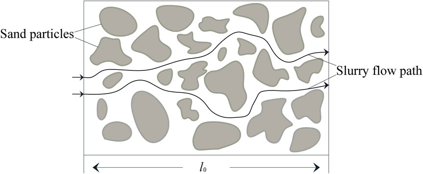
FIGURE 1. Schematic diagram of porous medium seepage channel.
The seepage channel in porous medium conforms to the fractal scale law, and the fractal form of seepage channel (Pitchumani and Ramakrishnan, 1999) can be specifically expressed as follows
Derivation of Eq. 1 gives:
Where: Dt is the fractal dimension of tortuosity of pore channel; b is the radius of the pore channel.Tortuous is usually defined as (Yu and Li, 2004)
The relationship between average tortuosity
The tortuosity fractal dimension of pore channels in porous medium (Yu and Li, 2001) can be expressed as
Where:
According to references (Yu, 2005), the average radius of pore channels in porous medium can be expressed as
The relationship between
The maximum radius of porous medium can be expressed by the following formula:
Where: Df is the fractal dimension of pore channels; bmin and bmax represent the minimum radius and maximum radius of porous medium pore channels, respectively; d+ is generally taken as 24; r is the average radius of particles in porous medium.
According to fractal theory, the fractal dimension of pores can be expressed as (Yun et al., 2008)
Reference (Yu and Cheng, 2002) gives the structural parameters of porous medium:
The expressions for the fractal dimension of the tortuosity of the pore channels in porous media can be obtained by combining (Eqs 4–10).
2.3 Temporal and spatial distribution equation of grouting pressure
According to advance mech mechanics of fluids in porous medium (Kong, 2010), the average velocity of Bingham fluid in a single seepage channel is
Where:
The seepage velocity v at any point in the injected porous medium, the average velocity of seepage channel at that point and the porosity of the porous medium satisfy (Li et al., 2013b):
Radius b of seepage channel of injected porous medium and permeability k satisfy (Kong, 2010):
Under the condition of constant grouting rate, the grouting flow rate meets
The pressure gradient along the diffusion direction of the Bingham fluid is obtained by combining (Eqs 12–15)
Substituting Eqs 2, 14 into Eq. 16 to obtain
When there is boundary condition
Grouting pressure at grouting port position
Where: q is the slurry flow rate; μ is the viscosity of slurry; S is the cross-sectional area of slurry diffusion; k is the permeability of the injected medium; τ0 is the initial yield stress of slurry; φ is the porosity of the injected medium; Dt is the tortuosity fractal dimension of seepage channel; p0 is the groundwater pressure; pc is the pressure at the grouting mouth.
3 Permeation grouting simulation experiment of sand body
3.1 Experiment device
In order to study the penetration diffusion mechanism of C-S slurry in sand body, a set of visual penetration grouting simulation experiment device has been designed, as shown in Figure 2. The experiment device consists of transparent plexiglass tube, pressure sensor, flow sensor, double-liquid mixer and manual grouting pump.
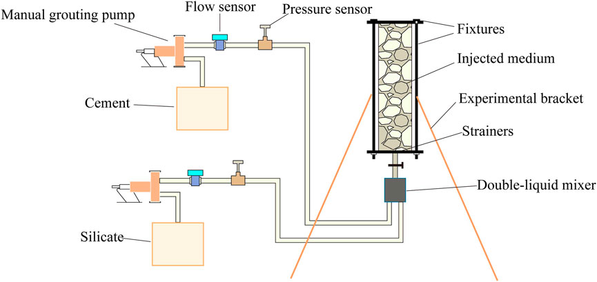
FIGURE 2. Schematic diagram of experiment device.
3.1.1 Permeation grouting tube
In order to obtain the dynamic process of slurry diffusion clearly and intuitively, the permeation grouting tube is made of PMMA (plexiglass), which can withstand the grouting pressure of 10 MPa. The permeation grouting tube is arranged vertically with an inner diameter of 10 cm and a length of 2 m. The inner part of the transparent plexiglas tube is filled with river sand as the injected medium with fixing device at both ends. The fixing device only allows the slurry to pass through and does not allow the injected medium to pass through, so as to prevent the whole movement of river sand during grouting.
3.1.2 Data recorder
In order to monitor the grouting rate and grouting pressure in the process of grouting in real-time, flow sensor and pressure sensor are set on the grouting tubeline. The pressure sensor has a measuring range of 0–10 MPa and a measuring accuracy of 0.02 MPa. The flow sensor has a measuring range of 0–30 L/min and a measuring accuracy of 0.3 L/min.
3.1.3 Manual grouting pump
The cement slurry and silicate slurry used in the experiment are pumped by manual grouting pump. The manual grouting pump can control the grouting pressure at 0–10 MPa and the pumping flow range is 0–10 L/min.
3.2 Viscosity time-dependent test of C-S slurry
The C-S slurry is a two-liquid slurry material made of a mixture of cement slurry and silicate slurry, the gel time of the slurry can be controlled within a few tens of seconds to a few minutes. The cement used for the test was 32.5R ordinary portland cement, the quality of the cement complied with the standard “Common Portland Cement” GB175-2007, the silicate modulus M=3.0, the concentration Be`=38, the water/cement ratio W/C is 1:1 and the mixing volume ratio is 1:1.
SV-10/SV-100 sine wave vibration viscometer (see Figure 3) is selected as the test instrument with a measuring range of 0.3–10,000 mPa s/1–100 Pa s. The viscosity and temperature curve of C-S slurry can be measured directly with time.
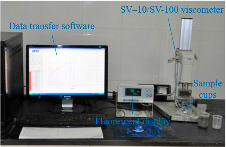
FIGURE 3. SV-10/SV-100 sine wave vibrating viscometer.
The curves of the viscosity and temperature of the C-S slurry with time are shown in Figure 4.
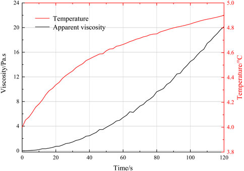
FIGURE 4. Viscosity and temperature curve of C-S slurry.
It can be seen from Figure 4 that although the temperature of slurry increases after mixing, the change range is within 1°C, so the slurry temperature can be considered to be basically unchanged. The initial viscosity growth of C-S slurry is small. With the reaction time, the slurry viscosity increases rapidly. The slurry viscosity curve can be fitted by power function form
Where:
3.3 Experiment plan
Three kinds of river sand with different particle size gradations are selected as the injected medium and the grouting experiment environment is anhydrous. The permeability coefficient and porosity of the injected medium are determined according to the constant head permeability test and “Standard for geotechnical testing method” (GB/T50123-1999, 1999).
The physical and mechanical parameters of the three types of river sands injected are shown in Table 1.

TABLE 1. The physical and mechanical parameters of injected medium.
During this experiment the grouting rate was kept constant and designed at 1, 2 and 3 L/min. 5 sets of experiment conditions were designed according to the porosity of the injected media and the grouting rate, as shown in Table 2.
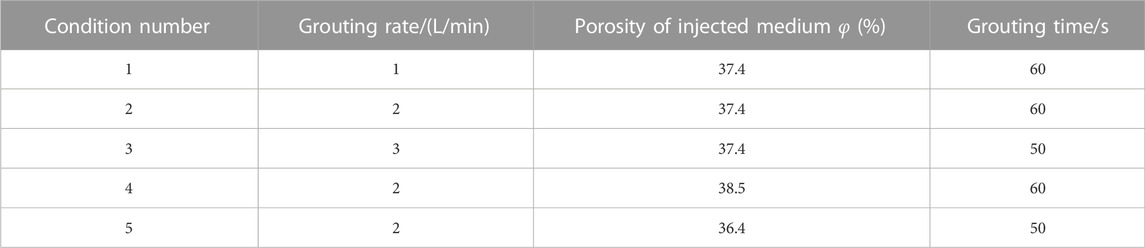
TABLE 2. Experiment conditions.
It is inevitable that there will be certain fluctuation of grouting rate when using manual grouting pump in the experiment. Therefore, it is considered that the fluctuation of grouting rate is constant within 10%.
4 Analysis of experimental results
With the growth of time, the slurry pressure is increasing, and the growth rate of slurry pressure also has a significant increase. The analysis suggests that the C-S slurry is at a low viscosity stage due to the low viscosity of the slurry mix at the beginning, the slurry viscosity grows slowly and the slurry flow diffusion resistance is at a low range; as time grows, the C-S slurry viscosity increases rapidly and the slurry flow diffusion resistance rises rapidly, making the grouting pressure increase as well. The variation curve of grouting pressure is shown in Figure 5.
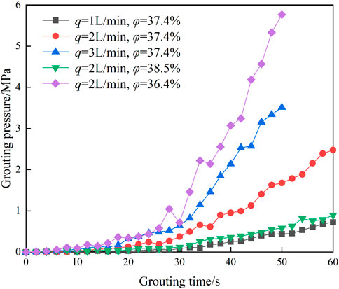
FIGURE 5. Grouting pressure variation curve under different conditions.
The grouting pressure is positively related to the grouting rate, while the grouting pressure is negatively related to the porosity of the injected medium.
5 Comparison and analysis of theoretical model and experimental results
During the experiment the diffusion front on the wall of the Plexiglas tube and the diffusion front in the river sand are basically consistent, the slurry is diffused in a one-dimensional form, the slurry diffusion distance can be directly obtained by measuring the position of the slurry front on the wall of the tube.
For one-dimensional diffusion penetration grouting, the diffusion distance and grouting time of grout meet:
The relationship between grouting pressure and diffusion distance in one-dimensional permeation diffusion process can be obtained by the simultaneous Eqs 19, 21.
Simultaneous (Eqs 16, 21) obtainable:
Whereas Eq. 22 is the temporal and spatial distribution equation of grouting pressure considering diffusion path and Eq. 23 is the temporal and spatial distribution equation of grouting pressure without considering seepage path.
Again, by substituting
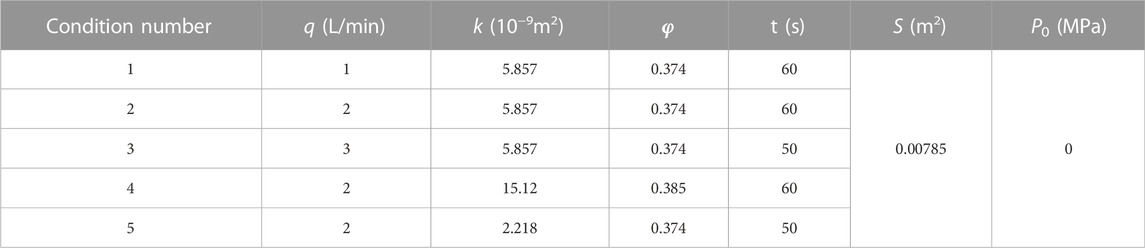
TABLE 3. Calculation parameters of theoretical model.
5.1 Analysis of the variation of grouting pressure with time
By substituting the relevant parameters into the variation of grouting pressure versus time equation, the variation of grouting pressure versus time curve can be obtained, and the specific calculation results are compared with the experimental data as shown in Figure 6.
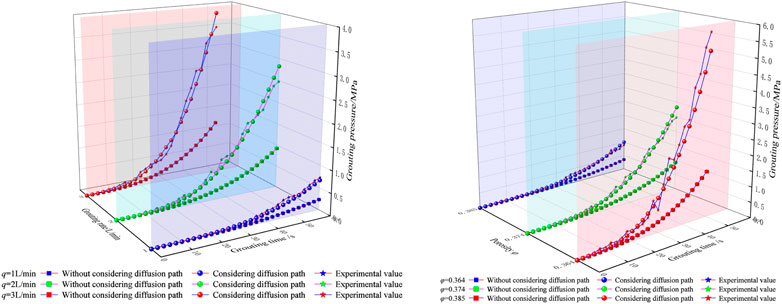
FIGURE 6. Variation curve of grouting pressure with time.
As can be seen from Figure 6, at the beginning of the grouting period, the grouting pressure is small and the growth rate is also small; as the grouting proceeds, there is a significant increase in the growth rate of the grouting pressure. There is a certain difference between the calculated results considering the slurry diffusion path compared to the model without considering the slurry diffusion path, and the theoretical difference increases with time. When the final design grouting time is reached, the calculated results considering the slurry diffusion path are 2.9–3.6 times higher than those without considering the slurry diffusion path, and the grouting pressure considering the slurry diffusion path is 0.9–1.1 times higher than the experimental results, and the experimental values are in good agreement with the theoretical.
5.2 Analysis of relationship between grouting pressure and diffusion distance
The calculated parameters are substituted into Eqs 22, 23 to obtain the variation curve of grouting pressure versus diffusion distance, and the specific calculated results are compared with the test data as shown in Figure 7.

FIGURE 7. Relationship curve between grouting pressure and diffusion distance. (A) Condition 1; (B) Condition 2; (C) Condition 3; (D) Condition 4; (E) Condition 5.
As can be seen from Figure 7, the grouting pressure has a significant effect on the slurry diffusion distance when the grouting pressure is at a low level; when the grouting pressure is at a high level, the slurry diffusion distance is significantly reduced by the grouting pressure. The theoretical model considering the diffusion path of slurry has a faster growth rate, while the theoretical model without the diffusion path has a slower growth rate, and the difference in slurry pressure increases as the diffusion distance increases. When the same diffusion distance as the test value is reached, the grouting pressure value obtained from the experimental is 2.4–4.1 times the value without considering the diffusion path, and the grouting pressure value obtained from the experimental is 0.7–1.2 times the theoretical value with considering the diffusion path, which is within the acceptable error range.
In summary, during penetration grouting, the grouting pressure values obtained from the experiment differed significantly from the calculated values without considering the diffusion path, while the calculated values considering the diffusion path agreed better with the experimental values, so it was necessary to consider the slurry diffusion path.
6 Conclusion
(1) Based on the fractal theory of porous media and the equation of seepage motion of viscous time-varying Bingham fluid, a theoretical model of permeation grouting with viscous time-varying Bingham fluid is established.
(2) The viscosity of the C-S slurry was tested and the variation curve of the viscosity of the C-S slurry with time was obtained. A set of permeation grouting simulation experiment device was designed, and the permeation grouting simulation experiment of C-S slurry was carried out to obtain the variation curve of grouting pressure with time under different injection media and different grouting rates.
(3) When the designed grouting time is reached, the calculation results considering the diffusion path are 2.9–3.6 times the results without the diffusion path, and the grouting pressure considering the slurry diffusion path is 0.9–1.1 times the experimental results.
(4) For the same diffusion distance conditions as the experimental, the grouting pressure values obtained from the experimental are 2.4–4.1 times the values obtained without considering the diffusion path, and the grouting pressure obtained from the experimental is 0.7–1.2 times the theoretical value considering the diffusion path.
Data availability statement
The raw data supporting the conclusion of this article will be made available by the authors, without undue reservation.
Author contributions
HW is mainly responsible for the overall writing of the full text. LD and QZ are responsible for data processing and analysis. ZL is responsible for the innovative ideas of the article. PZ are responsible for the test operation. All authors have read and agreed to the published version of the manuscript.
Funding
This work was supported by the National Natural Science Foundation of China (Grant No. 52109131); the Natural Science Foundation of Shandong Province (Grant No. ZR2020QE290); and the National Natural Science Foundation of China (Grant No. 52179120 and 52171267).
Conflict of interest
Author PZ was employed by Qingdao West Coast Rail Transit Co., Ltd.
The remaining authors declare that the research was conducted in the absence of any commercial or financial relationships that could be construed as a potential conflict of interest.
Publisher’s note
All claims expressed in this article are solely those of the authors and do not necessarily represent those of their affiliated organizations, or those of the publisher, the editors and the reviewers. Any product that may be evaluated in this article, or claim that may be made by its manufacturer, is not guaranteed or endorsed by the publisher.
References
Axelsson, M., Gustafson, G., and Fransson, Å. (2009). Stop mechanism for cementitious grouts at different water-to-cement ratios. Tunn. Und. Space Technol. 24, 390–397. doi:10.1016/j.tust.2008.11.001
Chen, X., and Yuan, C. (2021). Law of columnar penetration of Bingham type slurry in porous medium. J. Min. Safe. Eng. 38 (04), 800–809+856.
Feng, X., Liu, R., Li, S., Han, W., Zhao, S., and Wang, H. (2016). Characteristics of moving interface of grout considering deep bed filtration. Chin. J. Rock Mech. Eng. 35 (05), 1000–1008.
GB/T50123-1999 (1999). Standard for soil test method. Beijing, China: Ministry of Water Resources. (In Chinese).
Kim, J. S., Lee, I. M., Jang, J. H., and Choi, H. (2009). Groutability of cement-based grout with consideration of viscosity and filtration phenomenon. Int. J. Numer. Anal. Mater. Geomech. 33, 1771–1797. doi:10.1002/nag.785
Kong, X. (2010). Advance mech mechanics of fluids in porous medium. 2rd. Hefei: University of Science and Technology of China Press, 409.
Kuang, J., Zan, Y., and Wang, J. (2000). Theory and example of grouting in geotechnical engineering. 1rd ed. Beijing, China: Science press, 39–42.
Li, S., Liu, R., Zhang, Q., Sun, Z., Zhang, X., and Zhu, M. (2013). Research on C-S slurry diffusion mechanism with time-dependent behavior of viscosity. Chin. J. Rock Mech. Eng. 32 (12), 2415–2421.
Li, S., Zheng, Z., Liu, R., Feng, X., Sun, Z., and Zhang, L. (2015). Analysis of diffusion of grout in porous medium considering permeation effects. Chin. J. Rock Mech. Eng. 34 (12), 2401–2409.
Liu, J., Zhang, Z., Han, Y., and Wu, X. (2015). Backfilled grouting diffusion law and model of pressure on segments of shield tunnel considering viscosity variation of cement grout. Rock Soil Mech. 36 (02), 361–368.
Ma, H., Yang, M., and Xia, Q. (2000). Research on formula based on the theory of permeable grouting. Ind. Con. , 02, 47–50+61.
Pitchumani, R., and Ramakrishnan, B. (1999). A fractal geometry model for evaluating permeabilities of porous preforms used in liquid composite molding. Int. J. Heat. Mass Transf. 42 (2), 2219–2232. doi:10.1016/s0017-9310(98)00261-0
Yang, P., Tang, Y., Peng, Z., and Chen, A. (2006). Study on grouting simulating experiment in sandy gravels. Chin. J. Geotech. Eng. , 28, (12), 2134–2138.
Yang, X., Lei, J., Xia, L., and Wang, X. (2005). Study on grouting diffusion radius of exponential fluids. Rock Soil Mech. , 26, (11), 112–115.
Yang, X., Wang, X., and Lei, J. (2004). Study and application of Bingham slurry diffusion radius. J. Hydraul. Eng., 06, 75–79.
Yang, Z., Hou, K., Guo, T., and Ma, Q. (2011). Study of column-hemispherical penetration grouting mechanism based on Bingham fluid of viscous time-varying. Rock Soil Mech. 32 (09), 2697–2703.
Yang, Z., Lu, J., Wang, Y., Zhang, Z., Yang, Y., Zhu, Y., et al. (2021). Column penetration grouting mechanism for power-law fluids considering tortuosity effect of porous medium. Chin. J. Rock Mech. Eng. 40 (02), 410–418.
Yang, Z., Niu, X., Hou, K., Guo, Y., Liang, W., and Zhou, Z. (2016). Column penetration grouting mechanism researches based on Power-law fluid. J. Harbin Inst. Technol. 48 (03), 178–183.
Yang, Z., Niu, X., Hou, K., Guo, Y., Zhou, Z., Chen, F., et al. (2015). Study on diffusion parameters of Bingham fluid based on column-hemispherical penetration grouting. J. Sichuan Univ. Eng. Sci. Ed.), 47 (S2), 47–53.
Ye, F., Gou, C., Chen, Z., Liu, Y., and Zhang, J. (2013). Back-filled grouts diffusion model of shield tunnel considering its viscosity degeneration. China J. Highw. Transp. 26 (01), 127–134.
Ye, F., Gou, C., Liu, Y., and Sun, H. (2012). Half-spherical surface diffusion model of shield tunnel back-filled grouts. J. Tongji Univ. Nat. Sci.), 40 (12), 1789–1794.
Yu, B. (2005). Character for tortuous streamtubes in porous medium. Chin. Phys. Lett. 22 (1), 158–160.
Yu, B., and Cheng, P. (2002). A fractal permeability model for bi-dispersed porous media. Int. J. Heat. Mass Transf. 45 (14), 2983–2993. doi:10.1016/s0017-9310(02)00014-5
Yu, B., and Li, J. (2004). A geometry model for tortuosity of flow path in porous medium. Chin. Phys. Lett. 21 (8), 1569–1571.
Yu, B., and Li, J. (2001). Some fractal characters of porous medium. Fractals 09 (03), 365–372. doi:10.1142/s0218348x01000804
Yun, M., Yu, B., and Cai, J. (2008). A fractal model for the starting pressure gradient for Bingham fluids in porous media. Int. J. Heat. Mass Transf. 51 (5-6), 1402–1408. doi:10.1016/j.ijheatmasstransfer.2007.11.016
Zhang, L., Zhang, Q., Liu, R., Li, S., Wang, H., Li, W., et al. (2017). A study of the application of Brain Atlas with and without +Gz acceleration conditions. Rock Soil Mech. 38 (02), 443–448. doi:10.3233/THC-171347
Zhang, Q., Wang, H., Liu, R., Li, S., Zhang, L., Zhu, G., et al. (2018). Permeation grouting mechanism of porous medium considering diffusion paths of grout. Chin. J. Geotech. Eng. 40 (05), 918–924.
Zhou, J., Lu, J., Zhang, Y., and Wang, Z. (2019). Calculation formula of permeation grouting considering slurry viscosity variation. J. Mat. Sci. Eng. 37 (05), 758–762.
Keywords: permeation grouting, fractal theory, porous medium, diffusion path, viscous time-varying Bingham fluid, C-S slurry
Citation: Wang H, Dong L, Zhang Q, Li Z and Zhang P (2023) Permeation grouting mechanism of viscous time-varying fluid considering diffusion path. Front. Earth Sci. 10:1100196. doi: 10.3389/feart.2022.1100196
Received: 16 November 2022; Accepted: 12 December 2022;
Published: 30 January 2023.
Edited by:
Shengli Yang, China University of Mining and Technology, Beijing, ChinaCopyright © 2023 Wang, Dong, Zhang, Li and Zhang. This is an open-access article distributed under the terms of the Creative Commons Attribution License (CC BY). The use, distribution or reproduction in other forums is permitted, provided the original author(s) and the copyright owner(s) are credited and that the original publication in this journal is cited, in accordance with accepted academic practice. No use, distribution or reproduction is permitted which does not comply with these terms.
*Correspondence: Zhipeng Li, bGl6aGlwZW5nc2R1QDE2My5jb20=