 Bethany Rysak
 Julia F. W. Gale
 Stephen E. Laubach
 David A. Ferrill2
- 1Bureau of Economic Geology, Jackson School of Geosciences, University of Texas at Austin, Austin, TX, United States
- 2Southwest Research Institute, Space Science and Engineering Division, San Antonio, TX, United States
We use observations of hydraulic fractures in core, outcrop attributes of natural hydraulic fractures, and analogue models, to address how hydraulic fracture networks evolve. A slant core from the Wolfcamp Formation—an unconventional shale hydrocarbon reservoir in the Permian Basin of West Texas—collected within 18 m and 30 m of two hydraulically stimulated horizontal wells, provided an opportunity to examine hydraulic fractures directly. In approximately 183 m of core, 309 calcite-sealed natural opening-mode fractures and 375 hydraulic fractures were identified. Many hydraulic fractures in the core show complex morphology, including twist-hackle segmentation, diversion, and bifurcation; these structures most commonly develop at lithological bed boundaries and mechanical heterogeneities such as natural fractures and concretions. An outcrop of bed-parallel pavements in the Cretaceous Boquillas Formation in West Texas contains opening-mode fractures that likely formed by natural hydraulic fracturing. Fracture traces provide evidence of twist-hackle segmentation, and are typically associated with bed boundaries and preexisting bed-parallel stylolites. A laboratory study of hydraulic fracturing of 33 synthetic blocks of gypsum and hydrostone revealed fracture steps, diversions, twist hackles, and multiple overlapping fractures together with information on fracture growth directions. These complexities in the fracture network were dominantly nucleated at inclusions used to simulate pre-existing fractures, and as a result of mechanical heterogeneity introduced by the wellbore and perforations. Collectively, our results show that complex fracture networks are produced in hydraulic fracturing of self-sourced reservoir strata. Mechanical stratigraphic boundaries and other heterogeneities are likely to enhance fracture network complexity through the processes of segmentation, diversion, and bifurcation. These processes create multiple fracture strands, resulting in an increased number of hydraulic fractures over those initiated, thereby increasing total fracture surface area. Our study provides insight into hydraulic fracture network propagation, and has applications for evaluation, completion, production, and fracture modeling of unconventional reservoirs.
Introduction
Hydraulic fracture treatments inject fluids at pressure sufficient to break rock, creating fluid pathways that facilitate societally important engineering operations such as efficient extraction of oil and gas, and geothermal resources (Hubbert and Willis, 1957; Mahrer, 1999; Heider, 2021). The process of hydraulic fracturing also occurs in nature (e.g., Engelder et al., 1990; Fall et al., 2015). Based on theory and simple laboratory experiments, the classic view of industrial hydraulic fracture growth was one of single, symmetric, bi-wing fractures extending from the wellbore (e.g., Howard and Fast, 1970; Montgomery and Smith, 2010). These models, however, have proved to be oversimplified. With the advent of microseismic monitoring, mineback studies, and early core-through experiments, by the 1990s the hydraulic fracture process was perceived to create complex fracture patterns including near-wellbore and far-field fracture strands (e.g., Mahrer, 1999). The origin and pattern of interacting parallel and adjacent fractures and/or non-interacting highly separated fractures remains contentious and is the subject of extensive recent core-through experiments (e.g., Raterman et al., 2017; Gale et al., 2019; Wang et al., 2019; Gale et al., 2021). Complex induced hydraulic fracture networks—characterized by large fracture surface area—are essential to effective production from fine-grained (unconventional) hydrocarbon reservoirs.
Reactivation of preexisting natural fractures is recognized as one likely cause of complex hydraulic fracture growth based on mine-back experiments, core-through studies, and microseismic results (Teufel et al., 1984; Warpinski and Teufel, 1987; Gale et al., 2007; Fu et al., 2021). Exploring the possible role of pre-existing fractures in development of multi-strand industrial hydraulic fractures has dominated numerical and physical model studies for the past decade (e.g., Dahi-Taleghani and Olson, 2011; Lee et al., 2015; Schoenball et al., 2020). Numerical modeling studies (e.g., Smart et al., 2014) and analysis of microseismicity data (Busetti et al., 2014) from hydraulic fracturing, and outcrop investigations of natural fracturing (e.g., Ferrill et al., 2014; Gale et al., 2014; Ferrill et al., 2021) indicate complex damage of low-permeability fine-grained reservoir strata involving multiple failure modes (including tensile, hybrid, and shear).
The extensive focus on the possible role of pre-existing fractures (and other discontinuities) may lead to other important causes of multi-stand hydraulic fracture development during hydraulic fracturing to be overlooked. Long, continuous cores from hydraulic test sites in unconventional reservoirs provide the opportunity to investigate complex fracture networks and processes that contribute to their formation. Together with reexamination of physical model results and insights from natural examples of hydraulic fractures, these core observations lead to our conceptualization of multi-strand fracture formation that includes interaction with preexisting discontinuities and formation in relatively homogenous rock.
In this study, we use observations from slant core (cut at a high angle to induced fractures), natural outcrops, and physical models, to show that fracture splitting by processes including segmentation, bifurcation, and twist-hackle formation can lead to complex multi-strand hydraulic fracture networks. These processes are likely to be primarily responsible for the increased fracture density and clustering compared with classic bi-wing hydraulic facture models, and may influence the distribution of proppant-packs in the hydraulic fracture network.
Background: Core, Outcrop, and Model
Diversion, bifurcation, and segmentation are commonly observed fracture morphologies (Figure 1) Diversion of a fracture may take place along a plane of weakness such as a bedding plane or another fracture. Diversion can result in the complete reorientation of the fracture or be restricted to a short distance before the fracture reorients and continues to propagate in the original orientation (Figure 1A). Observations in core (Gale et al., 2018) and in laboratory experiments of interacting hydraulic and natural fractures (Lee et al., 2015) indicate the diversion step can be just a few centimeters long, but Ferrill et al. (1997) in a study of similar processes of diversion of dykes along faults showed the length of the step can be several kilometers, and is dependent on cohesion and dilation tendency of the pre-existing fracture. In some cases the fracture continues to propagate as well as divert, giving rise to two branches. Bifurcation is the branching of a fracture into two or more fractures oblique to the parent fracture (Figure 1B) (Bieniawski, 1968). Segmentation is caused by the breakdown of the propagating fracture tips, causing the fracture trace to split into multiple smaller fracture traces near the tips of parent fractures—these fractures are often referred to as fringe cracks (Woodworth, 1896; Younes and Engelder, 1999). Twist hackles are en echelon segments at the fringe of a main or “parent” opening-mode fracture, with the transition either occurring within a mechanical bed or at a mechanical boundary between rock layers (Figure 1C) (Younes and Engelder, 1999).
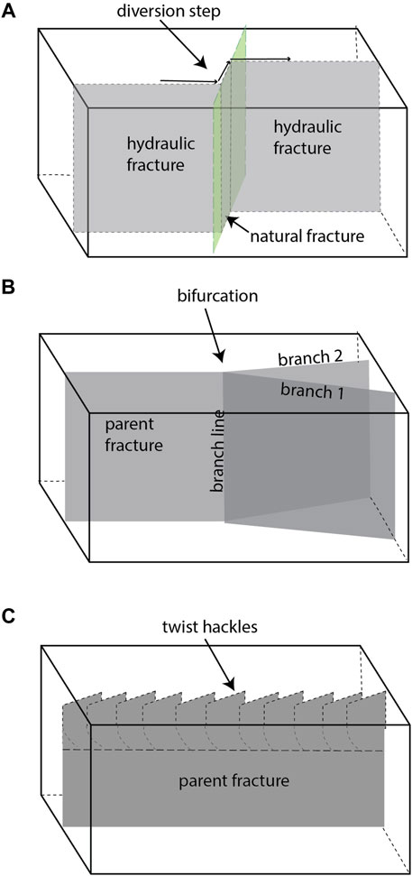
FIGURE 1. Schematic block diagrams of fracture morphological features observed in this study. (A) Hydraulic fracture diversion step along a natural fracture. (B) Fracture bifurcation, where a single parent fracture splits into two, non-parallel fractures. (C) Segmentation of a parent fracture into twist hackles oblique to the parent.
We investigated fracture diversion, bifurcation and segmentation in core, outcrop, and physical models because each data source provides different insights into the occurrence and development of complex fracture networks. Core-through observations are special opportunities to observe the geometry and interaction of fractures created in industrial hydraulic fracture treatments in a producing hydrocarbon reservoir. The limited view and small scale of core observations (microns to centimeters), however, precludes observation of the extended 3D patterns of fractures than can help clarify how the patterns formed. Moreover, these expensive experiments are naturally limited in number (only four in shale have been described: Raterman et al., 2017; Gale et al., 2018; Salahshoor and Ciezobka, 2020; Gale et al., 2021). Outcrops provide opportunities to observe natural fracture patterns in 3D in a range of states of development, within fine-grained unconventional reservoir strata. However, the processes of natural hydraulic fracturing differ from industrial hydraulic fracturing in that the former typically having lower driving stresses (e.g., Laubach et al., 2019 and references therein) occurring over geologic time scales rather than time scales of hours for typical induced hydraulic fracture treatments. Laboratory analog models allow the progressive development of fully 3D patterns and allow segmentation, bifurcation, and splitting mechanisms to be isolated. However, scaling model materials, structures, and rates in the laboratory can prove to be difficult.
The slant core analyzed in this study is from the Hydraulic Fracture Test Site (HFTS1) (Ciezobka et al., 2018). The core was collected from the eastern edge of the Midland Basin, in Reagan County in West Texas (Figures 2A,B) through a previously hydraulically fractured pad of 11 horizontal wells with the goal of capturing hydraulic fractures. The well was drilled along an azimuth of 345°, with a deviation of 82° (core axis plunges 8-degrees to the south) and passes within 18—32 m of the 6U stimulated well in the Wolfcamp A, and within 29.5—31 m of the lower 6 M stimulated well in the Wolfcamp B (Maity and Ciezobka, 2020) (Figure 2A). The 10-cm diameter core was collected in 6 sections totaling 183 m in length. The Wolfcamp Formation is a prolific hydrocarbon reservoir of early Permian age (299–285 Ma), composed of interlayered organic and carbonate rich mudrocks, siltstones, and carbonate rich debris flows (Ruppel, 2019). The diameter of the core is small with respect to the hydraulically stimulated volume; thus, the Wolfcamp slant core is effectively a line sample. Key information is obtainable from the core, including hydraulic fracture orientation, spacing and abundance of fractures, and detailed fracture morphology, including the occurrence of twist hackles on induced hydraulic fractures. 3-D architecture of hydraulic fractures at a larger scale, however, is not captured due to the small-diameter linear sample.
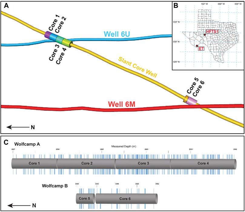
FIGURE 2. (A) Schematic view, looking East, of the slant core well and the 6U and 6 M horizontal wells, showing the location of the 6 discrete core sections. The 6U and 6 M wells are spaced 98 m apart vertically, and 100 m apart horizontally. The vertical dimension in this figure has been stretched ×20 and wellbore and core diameters have been increased for visualization purposes. (B) Map of Texas and the surrounding area, with the HFTS1 location labeled in West-Central Texas, and the Ernst Tinaja location labeled to the south near the Mexico border in West Texas. (C) Distribution of hydraulic fractures identified by Gale et al. (2018) in each of the 6 slant core sections.
The outcrop example is within the Cretaceous Boquillas Formation—lateral equivalent of the Eagle Ford Formation self-sourced reservoir in south Texas—at Ernst Tinaja, in Big Bend National Park in West Texas (see Ferrill et al., 2016; McGinnis et al., 2017; Lehrmann et al., 2019; Ferrill et al., 2021). The exposure contains abundant examples of natural opening-mode hydraulic fractures in several stages of development. The outcrop examples allow for the fracture complexities (e.g., twist hackles) observed in the slant core to be explored in the context of a large and complex natural fracture network exposed in three-dimensions. These natural fractures provide insights into twist hackle geometries associated with those at HFTS1, and present possible analogs for their formation.
To help constrain complex fracture development from controlled stimulation events, we analyzed fracture morphologies in benchtop analog models of hydraulic fracturing. The analog models were created during prior studies in labs at The University of Texas’ Hildebrand Department of Petroleum and Geosystems Engineering, and results provide insights for interpreting the core observations.
Methods and Results
Observations of Fractures in Core
Slant Core Analysis Methods
The slant core, together with a CT scan of the core, was examined for fractures by Gale et al. (2018), who developed criteria to identify hydraulic, natural, drilling-induced, and core-handling fractures. Here we specifically focus our analysis on hydraulic fracture morphology and its implications for the hydraulic fracture network.
Slant Core Results
In the initial slant core fracture description by Gale et al. (2018), 375 induced hydraulic fractures and 309 natural fractures were identified; here we show their distribution along the length of the cores (Figure 2C). In several locations, hydraulic fractures occur in clusters, with locally up to eight fractures present within a 1-m section. Many hydraulic fractures also exhibit fractographic features that may be linked to fracture growth and fracture segmentation such as diversion steps, twist hackles, and paired doublets (Gale et al., 2018).
Diversions where a fracture diverts along a plane of weakness for a distance (commonly less than a centimeter in core observations) before reorienting and continuing to propagate, are expressed in core as steps that extend part-way or all the way across the fracture face. In these cases, bedding planes, concretions, or natural fractures are the planes of weakness. The observed steps have variable geometries including 1) regular and sharp-angled (Figure 3A), 2) curved, smooth ramps (Figure 3B), or 3) highly irregular (Figure 3C).
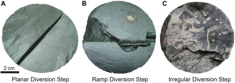
FIGURE 3. Three examples of different diversion step morphologies observed in core. (A) displays a sharp-angled step, (B) displays smooth, curved ramps, and (C) displays a highly irregular series of step and ramp features.
Observed twist hackles in the core include both gradual twist hackles representing continuous breakdown at the fracture tip, and abrupt twist hackles representing discontinuous breakdown of the fracture tip morphologies (e.g., Figure 4; Younes and Engelder, 1999). Breakdown is observed at the parent-fracture tip, resulting in the segmentation of the fracture into an en echelon arrays typically at a transition in bedding and/or a contrasting lithology. The local direction of propagation is indicated by the twist hackles in conjunction with accompanying plumose structure (Figures 4A,C). In total, 67 hydraulic fractures were observed to have twist hackle features in the HFTS1 slant core. Although propagation directions are variable, dominant propagation direction—represented by 72% of fractures with twist hackles—was vertical (Figures 4B,D). Of twist hackles observed in the slant core, 52% of the transitions are located near lithology changes, and 48% of the transitions are contained within the parent fracture bed.
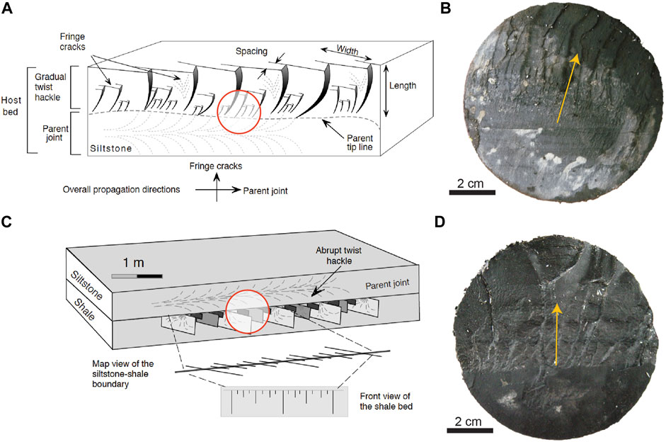
FIGURE 4. (A) Figure from Younes & Engelder (1999) showing gradual twist hackles forming from plumose within a bed and growing orthogonally, curving out and up and increasing in crack displacement to the bed boundary. The hypothetical location of (B) is shown with the red circle. (B) An example of a gradual twist hackle in core, with growth upward in the direction if the yellow arrow. (C) Figure from Younes & Engelder (1999) showing parent fracture with plumose structure in the overlying siltstone bed, with abrupt twist hackles forming orthogonally from the lower bed boundary and propagating into the underlying shale unit. The hypothetical location of part D is shown with the red circle where lithology changes and fracture breakdown is triggered. (D) An example of abrupt twist hackles in core, with indicated growth upward from the dark shale unit into the rough carbonate rich shale unit.
Bifurcation is the branching of a fracture into two fractures, giving rise to a closely spaced fracture pair or ‘doublet’. The double pairs appear to diverge in the direction of propagation, with propagation direction indicated by fracture surface marks (arrest lines, plumes). However, in the case that surface marks are not present to indicate growth direction, it cannot be ruled out that these features could also be caused by the coalescence of two fractures. Evidence of bifurcation in the HFTS1 core is indicated by the presence of 22 doublets with the core piece between the pair having a characteristic wedge shape, with the branchline of divergence for the doublets being a short distance (typically less than 2 cm) outside the core margin in most cases (Figure 5A). Because the divergence (i.e., branchline) was only observed in a few cases, we could not correlate divergence with specific structures and thus we did not establish a cause for the fracture branching. Determination of the direction of bifurcation for the observed doublets showed that the dominant bifurcation direction in the Wolfcamp A was to the west, and the dominant bifurcation direction in the Wolfcamp B was to the east (Figure 5B), which is consistent with propagation and bifurcation away from the adjacent horizontal well stimulation locations associated with the HFTS1 well pad. The presence of these bifurcation features in core samples collected 18–30 m from a stimulated wells shows that this process operates for a significant distance away from the wellbore. Of the 22 bifurcation doublets, 18 occur in the Wolfcamp A, and 4 occur in the Wolfcamp B.
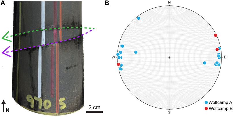
FIGURE 5. (A) Photograph of core showing fracture doublet from the slant core, with the northern doublet fracture colored green, and the southern doublet fracture colored purple. The point of divergence is likely located just outside the eastern margin of the core. Direction of bifurcation is indicated with the yellow arrow. (B) Bifurcation directions for doublets in the Wolfcamp A and B plotted on a lower hemisphere stereonet.
Overall, 44% of all hydraulic fractures seen in the core show some sort of segmentation or diversion feature. This represents a substantial subset of the overall population. Observation of diversions and twist hackles indicate that mechanical heterogeneities including natural fractures, concretions, or mechanical layer boundaries seem to play important roles in the initiation of these features. However, not all examples of diversions or twist hackles could be attributed to a particular forcing mechanism.
Diversions of hydraulic fractures along natural fractures take the form of natural fracture reactivation where the natural fracture is parted (Figure 6A), or a “jog”, across the natural fracture without initiating reactivation (Figure 6B). Of the 309 natural fractures observed in the core, 26 were characterized to have been hydraulically reactivated—indicated by the visible parting of calcite cement, and/or the presence of proppant within the parted fracture—and 12 showed morphological evidence for a hydraulic fracture jog. The likelihood of a diversion occurring at an intersection with a natural fracture depends on several variables such as bonding strength of the rock-cement interface, cement thickness, angle of approach, length of the discontinuity, and burial depth (Jeffrey et al., 2009; Lee et al., 2015; Wang et al., 2018). We note that Male et al. (2021) calculated that fewer than 1 in 10 natural fractures were reactivated in the HFTS1 slant core, suggesting that they could play a less-active role in inducing fracture complexity than commonly assumed.
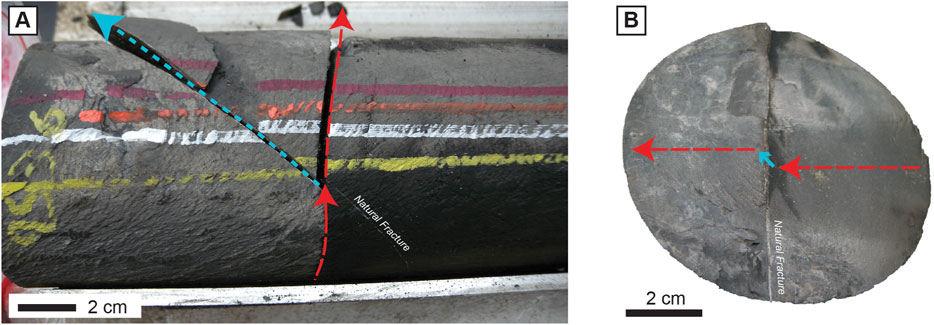
FIGURE 6. (A) Hydraulic fracture #376 propagating to the east (red) and being split and diverted along the NE-oriented part of a natural fracture (light blue). (B) Hydraulic fracture #579 (fracture face) propagating (red) and taking a slight jog up along a natural fracture (light blue) before reorienting and continuing to propagate.
Natural Outcrop Examples
Field Methods
The Ernst Tinaja arroyo in Big Bend National Park (West Texas) cuts NE-SW across Cuesta Carlota and drains the Ernst Basin half-graben along the western edge of the Sierra Del Carmen. The arroyo crosses a large SW-dipping panel exposing a substantial section of the lower and upper Cretaceous strata (Maxwell et al., 1967; Moustafa, 1988; Turner et al., 2011). This exposure includes a complete section of the Ernst Member of the Boquillas Formation, which is the lateral equivalent of the Eagle Ford Formation (Maxwell et al., 1967; Lehrmann et al., 2019). The Cretaceous strata in this area experienced SW-NE directed contraction during the Laramide orogeny in the early Paleogene (70–50 Ma; Lehman, 1991), followed by SW-NE directed Basin and Range extension in the Cenozoic (25–2 Ma; Turner et al., 2011). Laramide deformation features observable at the Ernst Tinaja exposure include contractional folds, thrust faults, and tectonic stylolites (Ferrill et al., 2016), and Basin and Range deformation includes normal faults and abundant extension fractures (McGinnis et al., 2017), with relative timing constrained by cross-cutting relationships (Ferrill et al., 2016, Ferrill et al., 2021).
Within this outcrop of the Boquillas Formation, we focus on two well-exposed pavements (bed-parallel exposures) within the lower portion of the Ernst Member that include both bedding-plane and profile exposures through their fracture networks (Figures 7A,C). The beds are composed of lime packstone and grainstone bounded by calcareous mudrock beds (Lehrmann et al., 2019; Frébourg et al., 2016). Pavements 1 and 2 represent tops of limestone beds at stratigraphic heights of 7.8 and 7.0 m in the measured section of Lehrmann et al. (2019) and the rebound profile of McGinnis et al. (2017) (Figure 7B). Beds throughout the exposure are cut by NW/SE-striking bed-perpendicular opening-mode fractures of Basin and Range origin, with spacings observed to be larger in the limestone beds than in the mudstone (McGinnis et al., 2017). Many of these fractures in the limestone beds exhibit twist hackles near bed boundaries—these twist hackles are most easily observed from above in map-view, and several can be seen in profile view along the top and/or bottom portions of beds (Figure 8). One-dimensional scanline surveys (azimuth 225°) were constructed perpendicular to the dominant opening-mode fracture orientation (parallel to the dip direction of bedding) to determine fracture spacing within the network (e.g., Priest and Hudson, 1981; Priest, 1993; Watkins et al., 2015; Gale et al., 2018). Scanline orientation was chosen to minimize the need for geometric corrections to spacing data. Following this work, the fracture pavement was characterized to assess the abundance, spacing, and orientations of twist hackles, and studied in profile to assess the vertical height of twist hackle extents and separation magnitudes. This combined fracture and twist hackle data was collected to provide insights and assist in interpreting similar fracture morphologies observed in the slant core.
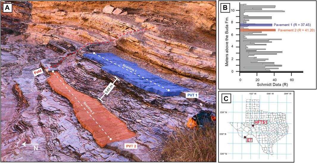
FIGURE 7. (A) Field photograph showing Pavement 1 highlighted in blue, and 0.65 m stratigraphically below, Pavement 2 highlighted in orange. A fold bounds their eastern edge; the trace of the fold axial plane is denoted with a red dashed line. The locations of Scanline 1 and Scanline 2 are shown with white dashed lines. (B) Schmidt hammer rebound profile for the bottom 10 m of the Ernst member modified from McGinnis et al. (2016; their Figure 5). Pavement 1 is highlighted in blue and Pavement 2 is highlighted in orange. It can be noted that both pavements have a significantly higher rebound value than the beds immediately adjacent. This rebound value (R) is a good indicator of mechanical stratigraphy present at Ernst Tinaja. (C) Map of Texas and the surrounding area, with the HFTS1 location labeled in West-Central Texas, and the Ernst Tinaja location labeled to the south near the Mexico border in West Texas.
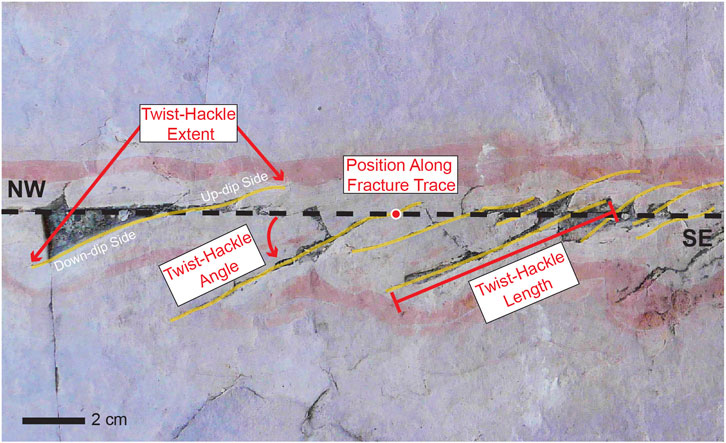
FIGURE 8. Outcrop photograph of twist hackles in map-view on Pavement 1, Fracture 12. The fracture trace is shown with the dashed black line, the position along the fracture trace, the twist-hackle length, the twist-hackle angle, which in this case is counter-clockwise, and the twist-hackle extent, which is on both sides of the fracture trace in this case, are all labeled and shown in red.
Outcrop Results
The scanline survey for Fracture Pavement 1 extended for 4.7 m and encountered 28 fractures. Of the sampled fractures, 19 (64%) contain twist hackles. Average bed thickness and fracture height for the Pavement 1 bed is 12 cm, fracture lengths (visible) range from 17 to 230 cm, and average fracture spacing is 16.9 cm (Table 1). The scanline for Fracture Pavement 2 extended for 4.8 m and encountered 29 fractures, of which 21 fractures (69%) contain twist hackles. Average bed thickness and fracture height for the Pavement 2 bed is 10 cm, fracture lengths (visible) range from 10 to 88 cm, and average fracture spacing is 16.7 cm (Table 1).
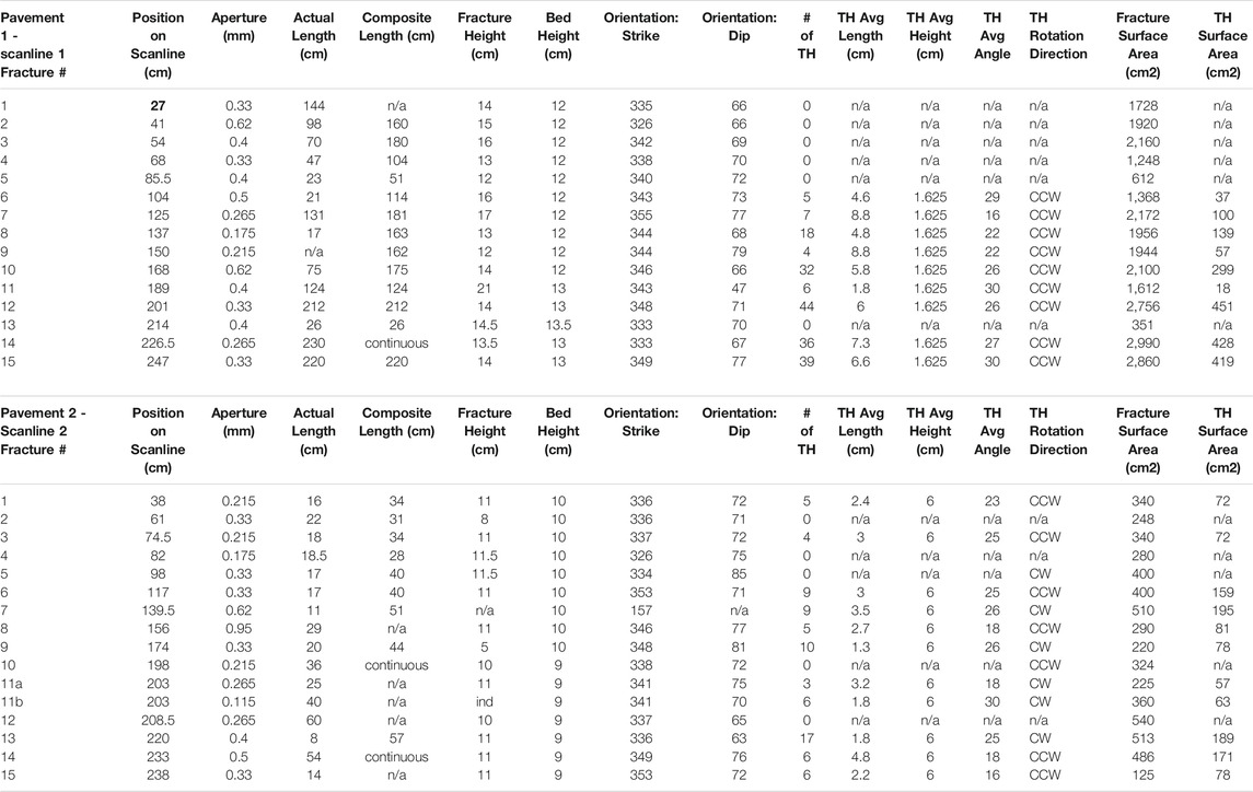
TABLE 1. A summary of the first 15 fractures recorded for Scanline 1 on Pavement 1, and Scanline 2 on Pavement 2. The full raw dataset for both scanlines can be found by referencing the Data Availability Statement.
In total across both pavements, 46 fractures were observed to have twist hackles. Hackles per-fracture range from 3 to 88, and varying locations of initiation along the parent fracture trace were observed. Using the height and length data collected for the twist hackles, we calculate that these en echelon arrays add between 6 and 20% of additional surface area to the fracture network compared with single, planar fractures with the same overall height and length dimensions (Table 1). Twist hackles on 49 fractures exhibit counterclockwise rotation with respect to the parent fracture and associated right-stepping arrangements, whereas only 6 fractures—all within pavement 2—show clockwise rotation and left-stepping arrangement (Figure 9A). The dominance of counterclockwise rotation and right-stepping arrangement of twist hackles is most consistent with an overall 26.5° counterclockwise rotation of the extension direction from an azimuth of ∼ 252° at the time of parent fracture formation, to ∼ 225.5° at the time of formation of the bulk of the twist hackles. The Pavement 2 fractures with clockwise-rotated twist hackles suggest another local stress reorientation to ∼ 099°.
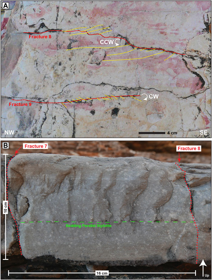
FIGURE 9. (A) Map-view photograph of Pavement 2, Fractures 8 & 9, traced in red. Twist hackles (traced in yellow) can be seen rotating counter-clockwise on Fracture 8, and clockwise on Fracture 9. (B) Profile-view photograph of a perpendicular joint in Pavement 2, located between Fractures 7 and 8, traced in red. Twist hackles can be seen emanating upward from a bed-parallel stylolite, located 6 cm from the top of the bed and traced in green.
The rebound profile for the Ernst Member of the Boquillas Formation at Ernst Tinaja (Figure 5 in McGinnis et al., 2017) documents mechanical stratigraphy using mechanical rebound (measured with an N-type Schmidt hammer) as a proxy for Young’s modulus and unconfined compressive strength. The profile shows that the Pavement 1 and 2 limestones are significantly more competent than the surrounding laminated calcareous mudrock (Figure 7B). In addition to mechanical layering, pre-existing deformation of Laramide age is also present in the outcrop (Ferrill et al., 2016; Ferrill et al., 2021), including thrust faults, tectonic stylolites, and folds. Both pavements studied crop out immediately west of a small fold. Such local structures as well as larger scale structural position with respect to the Basin and Range normal fault system in the Sierra del Carmen are likely to have combined to influence near-field stress orientations during fracture nucleation and reactivation, producing the observed twist hackle pattern (Figure 7A). We also see the combined effect of mechanical stratigraphy and preexisting deformation on a smaller scale in Pavement 2, where a bed-parallel stylolite serves as a transition for fracture breakdown and twist hackle formation (Figure 9B). We interpret that the parent fracture initially cut the lower portion of the bed, terminating against the bed-parallel stylolite. Subsequent renewed propagation upward through the bed in a stress field represented by a clockwise-rotated extension direction produced twist hackles in the upper part of the bed that are rotated clockwise from the parent fracture.
Physical Model Reexamination
Due to the difficulty involved with viewing hydraulic fractures directly, many scientists have turned to lab experiments to observe hydraulic fracture morphology (e.g., Blanton, 1982; Renshaw and Pollard, 1995; Zhou et al., 2008; Bahorich et al., 2012). The benefit of performing hydraulic fracture tests in the lab is that one can better control boundary conditions and make more complete observations. In this study, we reexamined physical analog models previously described by Bahorich et al. (2012).
Physical Model Analysis Methods
The majority of blocks examined in this study are in the form of 30 cm × 30 cm cubes poured in three layers, each with 10 cm average thickness. The bottom and top layers were made of hydrostone, which is a mixture of 75.5% cement and 24.3% water by weight (Bahorich et al., 2012). These hydrostone layers sandwich a central layer of gypsum plaster, which were 63% gypsum cement and 37% water by weight at the time the layers were poured (Bahorich et al., 2012). Due to their mechanical properties, the hydrostone layers are meant to serve as fracture barriers to the initiated hydraulic fracture, containing them within the middle layer (Bahorich et al., 2012). In total, 33 blocks were studied—of these, the middle layer in 18 of the blocks are homogeneous, and the middle layers in the other 15 blocks contain wafer-like inclusions of sandstone, glass, or plaster to simulate the presence of pre-existing natural fractures. Each block was hydraulically fractured using flat jacks on each face of the cube to simulate anisotropic stress conditions, with the vertical stress being dominant (Bahorich et al., 2012). Blocks contained anywhere from 1 to 4 vertically oriented “wellbores” made of 1 cm diameter aluminum tubing. Each wellbore contained one perforated interval which consisted of pre-drilled holes in the tubing oriented perpendicular to the wellbore. These perforations were filled with pipe cleaners that extended 2 cm out of the perforations into the block medium during the initial pouring and were removed through the wellbore after the block had hardened and prior to fracturing (see Bahorich et al., 2012). This provided an open cavity in the block for fluid to leave the wellbore and pressurize the surrounding medium. Following the hydraulic fracture of the blocks in the lab, each block was broken open to observe the hydraulic fractures inside, which are dyed red from dye included in the pressurized fluid.
Physical Model Observations
Overall, we found that 57% of the experimental block population (19 blocks) show evidence of fracture segmentation (Table 2). Simulated natural fractures appear to play the largest role in introducing complexity to the fracture network. Commonly, the interaction with natural fractures resulted in both fracture diversion, kinking, and the breakdown into twist hackles (Figure 10). These blocks show that 82% of observed twist hackles and 83% of observed diversions are the result of interaction between hydraulic fracture and natural-fracture simulants (wafer-like inclusions of sandstone, glass, or plaster), which also caused reactivation of the natural-fracture simulants.
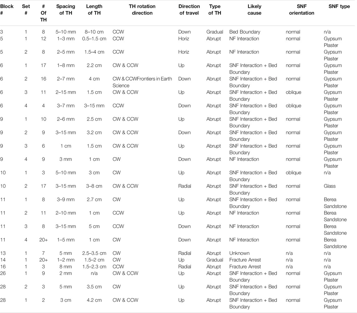
TABLE 2. All instances of twist hackles occurring within the studied experimental block population. It should be noted that multiple sets of hackles could be observed within one single block. TH, Twist Hackles; SNF, Simulated Natural Fracture. “SNF Orientation” refers to the orientation of the simulated natural fracture relative to the propagating fracture, with “normal” indicating that the SNF was oriented 90° to that of the propagating hydraulic fracture, and “oblique” indicating that the SNF was oriented less than 90° to that of the propagating hydraulic fracture. The full dataset for all blocks can be found by referencing the Data Availability Statement.
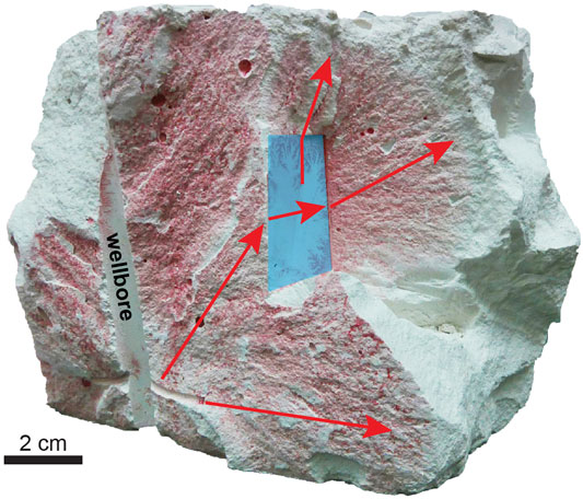
FIGURE 10. Block 10 showing the hydraulic fracture (shown with red arrows) emanating from the wellbore and then making a diversion step along a simulated natural fracture made of glass (highlighted in blue) followed by kinking and hackling off two ends.
In blocks with little heterogeneity (that is, few or no simulated natural-fractures), induced fractures also show non-uniform, branched shapes. Here the perforation, or in several cases the wellbore, appear to have served as the locus for generating non-uniformity in the fracture trace. Of the 18 observed homogeneous blocks (those without simulated natural fractures), 83% contained complex fracture morphology. A substantial source of the fracture-face irregularity observed in this lab study came from the perforations. Irregularity seems to arise from this contact point with the host medium, and then either grows into step and ramp features, or segments into multiple fractures (Figure 11). A lack of sealing around the wellbore was also observed to create step and ramp features in several blocks (Figures 11A,B). In some cases, fractures propagated in oblique orientations from the perforation (Figures 11C-F), and overlapped to create the appearance of multiple closely spaced fractures (Figure 12). This geometry looks very similar to that observed in the bifurcation doublets in the HFTS1 slant core. Most of these observations concerning fracture curving and overlap occurred in homogeneous blocks with 3 or more wellbores. It is likely that this behavior results from the presence of these multiple closely spaced wellbores, which creates a modified stress state, resulting in separate fracture wings growing from a single perforation in order to avoid each other. This is commonly referred to as the stress shadow effect (Pollard and Aydin, 1988).
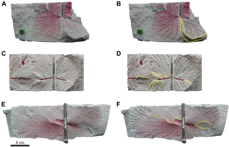
FIGURE 11. (A) Experimental Block 3 exhibiting two obliquely oriented fractures (stained red) emanating from the base of the wellbore. In (B) these features are highlighted, with plumose and fracture fringes highlighted using black dashed lines, and the gap between the two obliquely oriented fractures is shown with yellow lines. (C) Block 13 and (E) Block 22 exhibit fracture irregularities emanating from the perforations. (D,F) show these same blocks with plumose and step features annotated as above. Note that the wellbore diameter in each block is 1 cm.
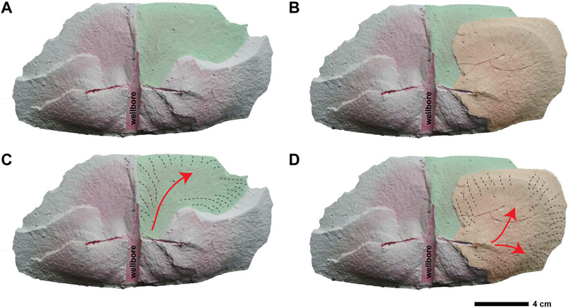
FIGURE 12. Block 20, Fracture 4 showing multiple fracture segments that grew from the wellbore perforations. Part (A) shows one fracture that appears to have grown upward from the wellbore and then propagated along a curved path (highlighted in green) while (B) shows a second fracture (highlighted in orange) that appears to grow both downward and upward from the perforation to overlap and link with the green-highlighted fracture. Parts (C,D) show these fractures with annotations for fracture growth direction (in red) and fracture plumose marks highlighted using black dashed lines.
Discussion
Findings from the slant core, outcrop study, and analog models show stratified mechanical heterogeneity coupled with stress-shadow effects and localized changes in the stress state can create complex fracture networks via fracture segmentation and diversion. Stratified mechanical properties and stratified natural fracture distributions typify sedimentary rocks (e.g., Laubach et al., 2009) and are a widespread feature of shales.
Twist hackles, bifurcations, and diversion steps, while formed via different processes, all contribute to the creation of more complex fracture networks by increasing fracture surface area and adding irregularity to the fracture surface topography. More complex fracture shapes are potentially self-propping owing to large-scale irregularities that may not easily re-seat after the hydraulic stress disturbance is removed or the sharp bends could serve to catch proppant, increasing overall network permeability.
Slant Core
In core we observed that most of the segmentation and diversion was tied back to mechanical heterogeneity. However, there is significant evidence that segmentation does operate outside of mechanical interactions, and likely responds to changes in the near and far field stress regime. We found that 207 segmented fractures, or 55% of the 375 hydraulic fractures identified in the core, occurred within the intervals that passed closest (65–90 ft; 20—28 m) to the stimulated wells (Gale et al., 2018) (Figure 2C). Work from Male et al. (2021) found that in addition to natural fracture network and lithology, distance to the nearest completion is one of the main factors dictating hydraulic fracture density. Proximity to completions could also explain the higher amount of bifurcation doublets found in the Wolfcamp A, as well as the increased heterogeneity present in the Wolfcamp A, or simply represent a sampling bias brought about by the smaller sample of Wolfcamp B core.
We hypothesize that as the fractures grew away from their point of origination at or near casing perforations at the wellbore, they began to branch and divide as they increased their radial distance from the wellbore. The HFTS1 results support this hypothesis but an important point to note is that each location along the slant core represents a different distance laterally and vertically from the stimulated wells. Thus the number of fractures is a product of both branching and proximity to the stimulated well; closer locations can have high numbers due to proximity as can more distant locations due to branching. During injection, the fluid pressure dissipates both temporally and spatially. Fluid pressure perturbation experiences radial damping, dissipating with radial distance from the source at the perforations through which fluid injection is occurring (see for example Figure 5B in Smart et al., 2014). The hydraulic fracture treatment injection also has a finite duration, typically measured in hours, at the end of which fluid pressure also dissipates. Thus the driver of the fracturing decreases with time and with distance from the wellbore increases, and the influence of far-field stresses and reservoir stress anisotropy then dominates. While we do not have a clear understanding of fracture growth directly around the wellbore during hydraulic fracturing, the results from the slant core study provide constraints on fracture intensity and bifurcation near stimulated wells.
While previous core-through studies have not focused on these same features, the high number of closely spaced fractures recovered provide potential evidence of fracture segmentation. In the Piceance Basin mine-back study, researchers recovered a 1.25 m interval with an average fracture spacing of 12 fractures per half-meter (Warpinski et al., 1993). At the Mobil’s Lost Hills research site, 10 hydraulic fractures were found in an interval that had been predicted to only contain two (Fast et al., 1994). In the ConocoPhillips core-through study in the Eagle Ford shale, researchers noted the presence of multiple hydraulic fracture doublets and triplets, with branching initiation points thought to be just outside the core margin (Raterman et al., 2017). It was also noted that the number of fractures found exceeded the number of perforation clusters in nearby stimulated wells believed to have contact with the core (Raterman et al., 2017; Sesetty and Ghassemi, 2019). In the HFTS1 study it was similarly noted that the number of fractures surpassed the number of perforation clusters in nearby stimulated wells (3 clusters per stage). Shrivastava et al. (2018) assumed only one fracture is generated per perforation cluster in their modeling of hydraulic fractures at HFTS1, but even if one fracture arises from each perforation shot, with 15 shots per cluster, there would still be fewer fractures than observed. While these past studies and the HFTS1 study involve different lithologies and different geologic formations, observations of twist hackle initiation, bifurcations, and steps along induced hydraulic fractures at lithologic transitions, as well as in homogeneous beds in the absence of natural fractures indicate that fracture segmentation and diversion operate with and without lithologic discontinuities present, and can potentially explain the large number of hydraulic fractures observed in each case.
Outcrop
This study of twist hackles in the field provides interesting insight into fracture network surface area relative to the limited view afforded by core. The HFTS1 slant core fractures mostly lack interpretable plumose surface marks suitable for estimating propagation direction, which makes the determination of twist-hackle angle and rotation direction difficult to document. Consequently, the fracture patterns away from the wellbore can only be inferred. However, with the wider view and much more data from outcrop, we can begin to piece together the causation behind the twist hackles at Ernst Tinaja as well as the impact of these features on fracture network surface area and (potentially) permeability. Previous studies have shown that twist hackle angle, measured in map view, is a function of the change in remote stress orientation, stress magnitude, and the rocks elastic properties (Pollard et al., 1982; Younes and Engelder, 1999). The multiple hackle rotation directions observed in outcrop point to the spatial change in local stress orientation, likely because of the nearby structural features (e.g., contractional folds and later normal faults) overprinted by the extensional fractures.
At Ernst Tinaja, mechanical stratigraphy, and preexisting deformation features such as bed-parallel stylolites, are spatially associated with twist hackle initiation points. We hypothesize that these features trigger fracture breakdown and the creation of en echelon arrays. Twist hackles at all scales increase overall fracture surface area, compared with fracture networks that lack twist hackles (e.g., Ferrill et al., 2014). The specific amounts of surface-area increase likely vary with the particular circumstances of fracture growth, so a direct comparison between the outcrop and HFTS1 core would be unlikely to be meaningful in detail. But in this outcrop, the surface area increase is, at least locally, as much as 20%. Owing to weathering, smaller hackles (less than 1 cm) are less visible and harder to measure and are undercounted. However, these small fractures are proportionally less significant for twist hackle surface area compared with longer hackles. Outcrop observations provide context to the HFTS1 dataset by highlighting the commonly stratigraphically controlled geometry of twist hackle features, and their overall significant contribution to the size and surface area of the fracture network.
Analog Models
Analog models provide a 3-dimensional view of fracture length and connectivity patterns that is impossible to derive from the limited view provided by core. The extent to which the patterns observed in the lab-generated analog models are present in the HFTS1 stimulated reservoir volume is unknown. The core penetrates a specific part of the stimulated volume, distant from the completed wellbore. In contrast to the evidence from core, the analog model dataset is dominated by the influence of hydraulic fracture–“natural” fracture interactions, which cause significant fracture diversion and natural fracture reactivation. In the HFTS1 slant core only 12% of observed natural fractures show reactivation within the core.
In addition, the prevalence of the many wellbore, and perforation-induced irregularities observed in the lab simulations shows that even in a relatively homogeneous medium, tortuosity and irregularity at the wellbore can still arise. Previous studies and modeling work has shown how these features can evolve due to completion methods, failure of casing, and various reservoir conditions (Sesetty and Ghassemi, 2019; Huang et al., 2020). While we cannot directly attribute the slant core features to these specific causes, it is likely that near-wellbore fracture tortuosity in the form of kinks, steps, and twist hackles, also occurs in the HFTS1 stimulated reservoir volume. Resultant features such as segmentation and perforation-related fracture overlap could have contributed to the large number of fractures and wide range of fracture orientations observed in the slant core.
Fracture Irregularity
The morphological features observed in core, outcrop, and in analog models, are indicative of more complex fracture growth than simple bi-wing, planar fractures. We present a schematic, conceptual diagram of hydraulic fractures emanating from a nominal point source (Figure 13). The point source could represent a flaw in host rock for a natural hydraulic fracture group, or part of a perforation cluster in a hydraulically fractured well such as the 6 S or 6 M wells in the HFTS1 project. The scale of the fracture features in the diagram could be from a few centimeters to many tens of meters. The three fractures generated show different morphological features, including plumose markings, arrest lines, twist hackles at different scales that arise at bedding interfaces, bifurcation, and diversions either at bedding or along a natural fracture. Parts of some fractures are featureless. Real fractures might exhibit all or none of these characteristics. To be consistent with observations of different propagation directions the diagram shows growth can be upward, downward, horizontal and all directions in between, depending on location. The diagram depicts more upward growth than downward growth, to be consistent with evidence of hydraulic fracture growth asymmetry from microseismic data (Gale et al., 2016).
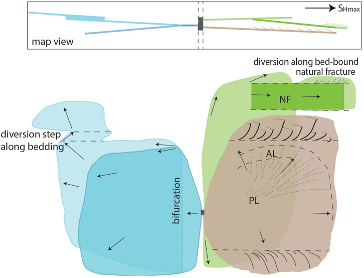
FIGURE 13. Schematic diagram showing map view (inset) of profile view of interpreted hydraulic fracture morphologies. Point source (grey rectangle) gives rise to three fractures (blue, buff, and green planes). Buff and green fractures propagate to the right and are slightly divergent. Morphological features: plumose markings, PL; arrest lines, AL; twist hackles, TH. Bedding: horizontal dashed lines. Propagation directions: arrows. The green fracture is featureless, until it partially diverts along a bed-bound natural fracture, and then continues upwards, but segments into small twist hackles. The blue fracture propagates in the opposite direction; the parent fracture is subparallel to the other fractures and SHmax until it bifurcates. The dark blue segment is in the foreground and is featureless. The light blue fracture diverts along bedding. Scale: a few cm to many tens of meters.
In general, the additional irregularity can have a significant impact on proppant dispersion and therefore, fracture network permeability. Material sampled from fracture faces in core revealed that significant accumulations of proppant occurred only where fractures show complex morphology including bifurcations and twist hackles (Elliott and Gale, 2018). Laser scans (3D) of the fracture faces in the core have shown that an increase in general fracture face roughness, due to morphology and/or lithology, correlates with higher proppant concentrations sampled from the core sleeve on a 3-ft (0.91 m) average (Maity and Ciezobka, 2020). The process of removing core from depth with fluid expansion and degassing, and the act of drilling to collect core could, however, alter the original proppant distribution through flushing of material from fractures. This process could even preferentially remove more material from the more planar fractures. Therefore, interpretation of the link between fracture morphology and original proppant distribution carries some uncertainty. Future work on the influence of the specific morphologies observed here to fluid and proppant transport may provide a more conclusive answer to the question of how fracture morphology impacts proppant distribution.
Conclusions
Core from stimulated rock volumes, outcrops with natural fracture networks, and simple physical models show that hydraulically driven fractures propagate along nonplanar paths marked by formation of subsidiary fracture branches. Single fractures commonly develop two or more surfaces (branches or segments) and a generally more complex morphology through twist hackles, bifurcation, and diversions.
Segmented fracture networks arise in rocks having discontinuities including mechanical layering, pre-existing fractures, and in the case of hydraulic fracture treatments discontinuities introduced by the drilling and completion process. The HFTS1 core results suggest that effective discontinuities in some mechanically layered self-sourced reservoir rocks are generated by rock property differences including bedding planes, bed-to-bed rock property contrasts, and variations in associated stress fields. A large amount of complexity arises as the fracture encounters changes in the local stress, brought about by vertical and lateral variations in mechanical properties that modify the stresses felt at the fracture tip, which may trigger fracture segmentation by breakdown, diversion, and branching. In addition, induced hydraulic fracturing is a dynamic process, with temporal variation in the rate of injection over a finite period of time, as well as radial damping of the pore pressure pulse modified by high permeability fractures, faults, and beds all likely altering local stress fields (i.e., magnitudes and orientations of principal effective stresses) during and after stimulation.
Complex networks of induced fractures and individual fracture morphologies define patterns that can result in increased fracture density and surface area. These attributes can enhance fracture/matrix interaction, which is critical for effective drainage of hydrocarbons from ultra-low permeability strata, as well as influence the effectiveness of fractures on fluid production. Complex, especially curved and kinked fractures, can potentially interfere with engineering operations such as proppant placement. In the slant core, instances of bifurcation added multiple fractures to the network that likely exceed the abundance of fractures created near the wellbore. In the field, we observed twist hackles that increase surface area of up to 20% compared with simple planar fractures. Both bifurcations and twist hackles were also observed to trap significant proppant in the slant core. Collectively, our results show that complex fracture networks are produced in hydraulic fracturing of self-sourced reservoir strata, and that mechanical layering and natural deformation fabrics such as natural fractures and stylolites are likely to enhance fracture network complexity.
Data Availability Statement
Publicly available datasets were analyzed in this study. This data can be found here: https://edx.netl.doe.gov/group/hfts-1-phase-1-group, https://repositories.lib.utexas.edu/handle/2152/94539.
Author Contributions
JG conducted the initial HFTS1 core description and fracture characterization. BR, JG, and SL contributed to the conception and design of this study incorporating the fracture description with lab and outcrop analogs. DF contributed to the planning of and background material for the outcrop analog study. BR wrote the first draft of the manuscript. All authors contributed to manuscript revision, and read and approved the submitted version.
Funding
The slant core description work was funded by a subcontract under the Gas Technology Institute (GTI) DOE-NETL contract DE-FE0024292. The field portion of this work was funded by the American Association of Petroleum Geologists (AAPG) Grants-in-Aid program. Further support was through the University of Texas at Austin Fracture Research and Application Consortium (FRAC).
Conflict of Interest
The authors declare that the research was conducted in the absence of any commercial or financial relationships that could be construed as a potential conflict of interest.
Publisher’s Note
All claims expressed in this article are solely those of the authors and do not necessarily represent those of their affiliated organizations, or those of the publisher, the editors and the reviewers. Any product that may be evaluated in this article, or claim that may be made by its manufacturer, is not guaranteed or endorsed by the publisher.
Acknowledgments
The authors would like to acknowledge: HFTS1 project manager Jordan Ciezobka, Laredo Petroleum, and members of the HFTS1 consortium; the US National Park Service for allowing entry to and data collection at Ernst Tinaja in Big Bend National Park; the members of the Southwest Research Institute (SwRI) Structural Geology & Geomechanics group for their previous work done at Ernst Tinaja which informed this study; Dr. Jon Olson for access to his lab and the block experiments done by his previous students; Sara Elliott for her work done on the HFTS1 core; Robin Dommisse and Dr. Frank Male for their time and work on the HFTS1 geomodel and statistical investigation.
References
Bahorich, B., Olson, J. E., and Holder, J. (2012). “Examining the Effect of Cemented Natural Fractures on Hydraulic Fracture Propagation in Hydrostone Block Experiments,” in Society of Petroleum Engineers - SPE Hydraulic Fracturing Technology Conference 2012, 4509–4529. doi:10.2118/160197-ms
Bieniawski, Z. T. (1968). “Propagation of Brittle Fracture in Rock,” in Basic and Applied Rock Mechanics (American Rock Mechanics Association), 409–427.
Blanton, T. L. (1982). An Experimental Study of Interaction between Hydraulically Induced and Pre-existing Fractures. Pittsburgh, Pennsylvania: SPE/DOE 10847 Unconventional Gas Recovery Symposium–21.
Busetti, S., Jiao, W., and Reches, Z. e. (2014). Geomechanics of Hydrolic Fracturing Microseismicity: Part 1. Shear, Hybrid, and Tensile Events. Bulletin 98, 2439–2457. doi:10.1306/05141413123
Ciezobka, J., Courtier, J., and Wicker, J. (2018). “Hydraulic Fracturing Test Site (HFTS) – Project Overview and Summary of Results,” in Unconventional Resources Technology Conference, Houston, Texas, USA, 25 July 2018, 9 (URTeC 2937168). doi:10.15530/urtec-2018-290235523
Dahi-Taleghani, A., and Olson, J. E. (2011). Numerical Modeling of Multistranded-Hydraulic-Fracture Propagation: Accounting for the Interaction between Induced and Natural Fractures. SPE J. 16 (3), 575–581. doi:10.2118/124884-PA
Elliott, S. J., and Gale, J. F. W. (2018). “Analysis and Distribution of Proppant Recovered from Fracture Faces in the HFTS Slant Core Drilled through a Stimulated Reservoir,” in SPE/AAPG/SEG Unconventional Resources Technology Conference 2018 (URTC), 1–10. doi:10.15530/urtec-2018-29026292018
Engelder, T., Lacazette, A., Barton, N., and Stephansson, O. (1990). Natural Hydraulic Fracturing. Rock Joints, 35–44.
Fall, A., Eichhubl, P., Bodnar, R. J., Laubach, S. E., and Davis, J. S. (2015). Natural Hydraulic Fracturing of Tight-Gas sandstone Reservoirs, Piceance Basin, Colorado. Geol. Soc. America Bull. 127 (1-2), 61–75. doi:10.1130/B31021.1
Fast, R. E., Murer, A. S., and Timmer, R. S. (1994). Description and Analysis of Cored Hydraulic Fractures-Lost Hills Field, Kern County, California. SPE Prod. Facil. 9 (2), 107–114. doi:10.2118/24853-pa
Ferrill, D. A., Connor, C. B., Stamatakos, J. A., McKague, H. L., Hill, B. E., Ofoegbu, G. I., et al. (1997). “Modeling Fault-Dike Interaction: Implications for Lateral Diversion of Dikes and Alignments of Volcanoes in the Yucca Mountain (Nevada) Region,” in CNWRA Report to the US Nuclear Regulatory Commission (San Antonio, TX: CNWRA). IM20-5708-471-760.
Ferrill, D. A., McGinnis, R. N., Morris, A. P., Smart, K. J., Sickman, Z. T., Bentz, M., et al. (2014). Control of Mechanical Stratigraphy on Bed-Restricted Jointing and normal Faulting: Eagle Ford Formation, South-central Texas. Bulletin 98, 2477–2506. doi:10.1306/08191414053
Ferrill, D. A., Morris, A. P., Wigginton, S. S., Smart, K. J., McGinnis, R. N., and Lehrmann, D. (2016). Deciphering Thrust Fault Nucleation and Propagation and the Importance of Footwall Synclines. J. Struct. Geology. 85, 1–11. doi:10.1016/j.jsg.2016.01.009
Ferrill, D. A., Smart, K. J., Cawood, A. J., and Morris, A. P. (2021). The Fold-Thrust belt Stress Cycle: Superposition of normal, Strike-Slip, and Thrust Faulting Deformation Regimes. J. Struct. Geology. 148, 104362. doi:10.1016/j.jsg.2021.104362
Frébourg, G., Ruppel, S. C., Loucks, R. G., and Lambert, J. (2016). Depositional Controls on Sediment Body Architecture in the Eagle Ford/Boquillas System: Insights from Outcrops in West Texas, United States. Bulletin 100, 657–682. doi:10.1306/12091515101
Fu, P., Schoenball, M., Ajo Franklin, J. B., Chai, C., Maceira, M., Morris, J. P., et al. (2021). Close Observation of Hydraulic Fracturing at EGS Collab Experiment 1: Fracture Trajectory, Microseismic Interpretations, and the Role of Natural Fractures. J. Geophys. Res. Solid Earth 126 (7). doi:10.1029/2020jb020840
Gale, J. F. W., Elliott, S. J., and Laubach, S. E. (2018). “Hydraulic Fractures in Core from Stimulated Reservoirs: Core Fracture Description of HFTS Slant Core, Midland Basin, West Texas,” in SPE/AAPG/SEG Unconventional Resources Technology Conference 2018, Midland Basin, West Texas (URTC), 2018, 1–14. doi:10.15530/urtec-2018-2902624
Gale, J. F. W., Elliott, S. J., Li, J. Z., and Laubach, S. E. (2019). “Natural Fracture Characterization in the Wolfcamp Formation at the Hydraulic Fracture Test Site (HFTS),” in SPE/AAPG/SEG Unconventional Resources Technology Conference, Midland Basin, Texas Texas (URTEC-644). doi:10.15530/urtec-2019-644
Gale, J. F. W., Elliott, S. J., Rysak, B. G., Ginn, C. L., Zhang, N., Myers, R. D., et al. (2021). “Fracture Description of the HFTS-2 Slant Core, Delaware Basin, West Texas,” in SPE/AAPG/SEG Unconventional Resources Technology Conference (OnePetro). doi:10.15530/urtec-2021-5175
Gale, J. F. W., Elliott, S. J., Rysak, B. G., and Laubach, S. E. (2016). The Critical Role of Core in Understanding Hydraulic Fracturing. Core Values: Geological Society of London Special Publications. (in review)The Role of Core in 21st Century Reservoir Characterization.
Gale, J. F. W., Laubach, S. E., Olson, J. E., Eichhuble, P., and Fall, A. (2014). Natural Fractures in Shale: A Review and New Observations. Bulletin 98, 2165–2216. doi:10.1306/08121413151
Gale, J. F. W., Reed, R. M., and Holder, J. (2007). Natural Fractures in the Barnett Shale and Their Importance for Hydraulic Fracture Treatments. Bulletin 91, 603–622. doi:10.1306/11010606061
Heider, Y. (2021). A Review on Phase-Field Modeling of Hydraulic Fracturing. Eng. Fracture Mech. 253, 107881. doi:10.1016/j.engfracmech.2021.107881
Howard, G. C., and Fast, C. R. (1970). Hydraulic Fracturing. New York: Society of Petroleum Engineers of AIME, 210.
Huang, L., Liu, J., Zhang, F., Fu, H., Zhu, H., and Damjanac, B. (2020). 3D Lattice Modeling of Hydraulic Fracture Initiation and Near-Wellbore Propagation for Different Perforation Models. J. Pet. Sci. Eng. 191, 107169. doi:10.1016/j.petrol.2020.107169
Hubbert, M. K., and Willis, D. G. (1957). Mechanics of Hydraulic Fracturing. Trans. AIME 210 (01), 153–168. doi:10.2118/686-g
Jeffrey, R. G., Bunger, A., Lecampion, B., Zhang, X., Chen, Z., Van As, A., et al. (2009). “Measuring Hydraulic Fracture Growth in Naturally Fractured Rock,” in Proceedings of SPE Annual Technical Conference and Exhibition, Jan. 6, 2009, 3750–3768. doi:10.2118/124919-ms
Laubach, S. E., Lander, R. H., Criscenti, L. J., Anovitz, L. M., Urai, J. L., Pollyea, R. M., et al. (2019). The Role of Chemistry in Fracture Pattern Development and Opportunities to advance Interpretations of Geological Materials. Rev. Geophys. 57 (3), 1065–1111. doi:10.1029/2019RG000671
Laubach, S. E., Olson, J. E., and Gross, M. R. (2009). Mechanical and Fracture Stratigraphy. Bulletin 93 (11), 1413–1426. doi:10.1306/07270909094
Lee, H. P., Olson, J. E., Holder, J., Gale, J. F. W., and Myers, R. D. (2015). The Interaction of Propagating Opening Mode Fractures with Preexisting Discontinuities in Shale. J. Geophys. Res. Solid Earth 120 (1), 169–181. doi:10.1002/2014JB011358
Lehman, T. M. (1991). Sedimentation and Tectonism in the Laramide Tornillo Basin of West Texas. Sediment. Geology. 75, 9–28. doi:10.1016/0037-0738(91)90047-h
Lehrmann, D. J., Yang, W., Sickmann, Z. T., Ferrill, D. A., McGinnis, R. N., Morris, A. P., et al. (2019). Controls on Sedimentation and Cyclicity of the Boquillas and Equivalent Eagle Ford Formation from Detailed Outcrop Studies of Western and Central Texas, U.S.A. J. Sed. Res. 89, 629–653. doi:10.2110/jsr.2019.38
Mahrer, K. D. (1999). A Review and Perspective on Far-Field Hydraulic Fracture Geometry Studies. J. Pet. Sci. Eng. 24 (1), 13–28. doi:10.1016/s0920-4105(99)00020-0
Maity, D., and Ciezobka, J. (2020). A Data Analytics Framework for Cored Fracture Imaging and Novel Characterization Workflow-Application on Samples from Hydraulic Fracturing Test Site HFTS in the Midland Basin. SPE-199754-MS: Society of Petroleum Engineers, 1–12.
Male, F., Rysak, B. G., and Dommisse, R. D. (2021). Statistical Analysis of Fractures from the Hydraulic Fracture Test Site 1: SPE/AAPG/SEG Unconventional Resources Technology Conference 2021. URTeC 2021, 1–15.
Maxwell, R. A., Lonsdale, J. T., Hazzard, R. T., and Wilson, J. A. (19676711). Geology of the Big Bend National Park, Brewster County, Texas. University of Texas at AustinBureau of Economic Geology Publication.
McGinnis, R. N., Ferrill, D. A., Morris, A. P., Smart, K. J., and Lehrmann, D. (2017). Mechanical Stratigraphic Controls on Natural Fracture Spacing and Penetration. J. Struct. Geology. 95, 160–170. doi:10.1016/j.jsg.2017.01.001
Montgomery, C. T., and Smith, M. B. (2010). Hydraulic Fracturing: History of an Enduring Technology. J. Pet. Tech. 62 (12), 26–40. doi:10.2118/1210-0026-jpt
Moustafa, A. R. (1988). Structural Geology of Sierra del Carmen, Trans-Pecos Texas. 1:48,000 scale geologic map. Austin, Texas: Bureau of Economic Geology, The University of Texas at Austin. Geologic Quadrangle Map, 54.
Pollard, D. D., and Aydin, A. (1988). Progress in Understanding Jointing over the Past century. Geol. Soc. America Bull. 100 (8), 1181–1204. doi:10.1130/0016-7606(1988)100<1181:piujot>2.3.co;2
Pollard, D. D., Segall, P., and Delaney, P. T. (1982). Formation and Interpretation of Dilatant Echelon Cracks. Geol. Soc. America Bull. 93, 1291–1303. doi:10.1130/0016-7606(1982)93<1291:faiode>2.0.co;2
Priest, S. D. (1993). Discontinuity Analysis for Rock Engineering. London, United Kingdom: Chapman & Hall.
Priest, S. D., and Hudson, J. A. (1981). Estimation of Discontinuity Spacing and Trace Length Using Scanline Surveys. Int. J. Rock Mech. Mining Sci. Geomechanics Abstr. 18, 183–197. doi:10.1016/0148-9062(81)90973-6
Raterman, K. T., Farrell, H. E., Mora, O. S., Janssen, A. L., Busetti, S., McEwan, J., et al. (2017). “Sampling a Stimulated Rock Volume: An Eagle Ford Example,” in Proceedings of the Unconventional Resources Technology Conference (URTeC), Austin, Texas (U.S.A.), 937–954. paper 2670034. doi:10.15530/URTEC-2017-2670034
Renshaw, C. E., and Pollard, D. D. (1995). An Experimentally Verified Criterion for Propagation across Unbounded Frictional Interfaces in Brittle, Linear Elastic Materials. Int. J. Rock Mech. Mining Sci. Geomechanics Abstr. 32, 237–249. doi:10.1016/0148-9062(94)00037-4
Ruppel, S. C. (2019). “Anatomy of a Paleozoic basin: the Permian Basin, USA: Introduction, Overview, and Evolution,” in Anatomy of a Paleozoic basin: The Permian Basin. Editor S. C. Ruppel (USA: The University of Texas at Austin, Bureau of Economic Geology Report of Investigations 285), 1. ch. 1)AAPG Memoir 118, 1–27.
Salahshoor, S., and Ciezobka, J. (2020). “Hydraulic Fracturing Test Site HFTS Phase-2 EOR Pilot: Huff-And-Puff Pilot in the Permian-Midland Basin,” in SPE Improved Oil Recovery Conference, Tulsa Oklahoma (SPE-200468-MS), 9. doi:10.2118/200468-MS
Schoenball, M., Ajo‐Franklin, J. B., Blankenship, D., Chai, C., Chakravarty, A., and Dobson, P.EGS Collab Team (2020). Creation of a Mixed-Mode Fracture Network at Mesoscale through Hydraulic Fracturing and Shear Stimulation. J. Geophys. Res. Solid Earth 125 (12), e2020JB019807. doi:10.1029/2020jb019807
Sesetty, V., and Ghassemi, A. (2019). “Simulation and Analysis of Fracture Swarms Observed in the eagle ford Field experiment: Society of Petroleum EngineersSimulation and Analysis of Fracture Swarms Observed in the Eagle Ford Field Experiment,” in SPE Hydraulic Fracturing Technology Conference and Exhibition 2019 (HFTC). 2019. doi:10.2118/194328-ms
Smart, K. J., Ofoegbu, G. I., Morris, A. P., McGinnis, R. N., and Ferrill, D. A. (2014). Geomechanical Modeling of Hydraulic Fracturing: Why Mechanical Stratigraphy, Stress State, and Pre-existing Structure Matter. Bulletin 98, 2237–2261. doi:10.1306/07071413118
Teufel, L. W., Hart, C. M., Sattler, A. R., and Clark, J. A. (1984). “Determination of Hydraulic Fracture Azimuth by Geophysical, Geological, and Oriented-Core Methods at the Multiwell Experiment Site, Rifle, CO,” in SPE Annual Technical Conference and Exhibition (OnePetro). doi:10.2118/13226-ms
Turner, K. J., Berry, M. E., Page, W. R., Lehman, T. M., Bohannon, R. G., Scott, R. B., et al. (2011). Geologic Map of Big Bend National Park, Texas. U. S. Geol. Surv. Scientific Invest. Map 3142, 84. scale 1:75,000, pamphlet.
Wang, S., Tan, Y., Sangnimnuan, A., Kahn, S., Liang, B., and Rijken, P. (2019). “Learnings from the Hydraulic Fracturing Test Site (HFTS)# 1, Midland Basin, West Texas—A Geomechanics Perspective,” in Unconventional Resources Technology Conference (URTeC), Denver, Colorado, July 2019 (Society of Exploration Geophysicists), 22–24. (pp. 2906-2922.
Wang, W., Olson, J. E., Prodanović, M., and Schultz, R. A. (2018). Interaction between Cemented Natural Fractures and Hydraulic Fractures Assessed by Experiments and Numerical Simulations. J. Pet. Sci. Eng. 167, 506–516. doi:10.1016/j.petrol.2018.03.095
Warpinski, N. R., Lorenz, J. C., Branagan, P. T., Myal, F. R., and Gall, B. L. (1993). Examination of a Cored Hydraulic Fracture in a Deep Gas Well. SPE Prod. Facil. 8 (3), 150–158. doi:10.1016/0148-9062(94)92893-210.2118/22876-pa
Warpinski, N. R., and Teufel, L. W. (1987). Influence of Geologic Discontinuities on Hydraulic Fracture Propagation. J. Pet. Tech. 39 (2), 209–220. doi:10.2118/13224-pa
Watkins, H., Bond, C. E., Healy, D., and Butler, R. W. H. (2015). Appraisal of Fracture Sampling Methods and a New Workflow to Characterise Heterogeneous Fracture Networks at Outcrop. J. Struct. Geology. 72, 67–82. doi:10.1016/j.jsg.2015.02.001
Woodworth, J. E. (1896). On the Fracture System of Joints, with Remarks on Certain Great Fractures. Boston Soc. Nat. Hist. Proc. 27, 63–183.
Younes, A. I., and Engelder, T. (1999). Fringe Cracks: Key Structures for the Interpretation of the Progressive Alleghanian Deformation of the Appalachian Plateau. GSA Bull. 111 (2), 219–239. doi:10.1130/0016-7606(1999)111<0219:fcksft>2.3.co;2
Keywords: morphology, twist hackle, fringe crack, bifurcation, hydraulic fracture, natural fracture, wolfcamp formation
Citation: Rysak B, Gale JFW, Laubach SE and Ferrill DA (2022) Mechanisms for the Generation of Complex Fracture Networks: Observations From Slant Core, Analog Models, and Outcrop. Front. Earth Sci. 10:848012. doi: 10.3389/feart.2022.848012
Received: 03 January 2022; Accepted: 07 March 2022;
Published: 29 March 2022.
Edited by:
Junlong Shang, University of Glasgow, United KingdomReviewed by:
Jianguo Wang, China University of Mining and Technology, ChinaJunxin Guo, Southern University of Science and Technology, China
Copyright © 2022 Rysak, Gale, Laubach and Ferrill. This is an open-access article distributed under the terms of the Creative Commons Attribution License (CC BY). The use, distribution or reproduction in other forums is permitted, provided the original author(s) and the copyright owner(s) are credited and that the original publication in this journal is cited, in accordance with accepted academic practice. No use, distribution or reproduction is permitted which does not comply with these terms.
*Correspondence: Bethany Rysak, YmV0aGFueS5yeXNha0B1dGV4YXMuZWR1