 Xiushan Wu
 Jiamin Cui2
- 1Key Laboratory for Technology in Rural Water Management of Zhejiang Province, Hangzhou, China
- 2School of Electrical Engineering, Zhejiang University of Water Resources and Electric Power, Hangzhou, China
- 3College of Mechanical and Electrical Engineering, China Jiliang University, Hangzhou, China
Seepage in the underground rock and soil is one of the main causes of geological disasters. Precursor information for geological disasters is provided by accurately measuring the seepage flow in rock and soil, so as to provide disaster warnings in time. This article analyzes the principle of seepage measurement in rock and soil based on heat transfer, deduces the relationship between the flow rate and temperature of the fluid with a seepage sensor, designs and manufactures an entire seepage measurement sensor, and designs a seepage measurement circuit. Finally, a set of portable geotechnical seepage measuring instruments is designed. An experimental platform is designed to realize seepage flow and temperature change experiments with the seepage sensor, it is proved that the sensor can effectively measure the seepage flow for different experimental samples, the measurement range is 0.06–0.160 ml/s. Based on the measured characteristic temperature of the seepage sensor, the calculated seepage flow is obtained, the relative error between the calculated value and the measured value is within 3%.
Introduction
China has a large land area and a complex geological environment. As changes in natural conditions and the intensity of human engineering activities increase, the number of geological disasters caused by seepage deformation and ground subsidence caused by seepage in rock and soil is increasing year by year. Seepage in rock and soil refers to the flow of water in the porous media of underground soil and rock. Seepage in rock and soil can cause the seepage deformation of rock and soil and causes ground settlement (Wang et al., 2018), which can cause geological disasters such as leakages of gates and dams, the collapse of dams, instability of foundation pit slopes, landslides, soil movement, underground equipment damage, and building collapse (Ghafoori et al., 2020). The areas prone to geological disasters in China account for about 65% of China’s total land area. As of 2018, according to statistics, the country has nearly 230,000 hidden danger points of geological disasters, among which 25,000 are prone to super-large and large-scale geological disasters, which would seriously threaten the personal and economic safety of human beings.
Precursor information for the occurrence of geological disasters such as landslides and mudslides can be provided by measuring the seepage flow in rock and soil, so as to provide timely disaster warnings and to protect people’s lives. The current research on seepage measurement in rock and soil mainly focuses on the rule of water movement in rock and soil and the distribution of the seepage field, so that the degree of seepage can be calculated through the thickness of the permeable foundation, the permeability coefficient, etc. (He et al., 2021). Then, the potential of geological damage occurring is determined, and reasonable anti-seepage measures are given to effectively control the impact of seepage in rock and soil on the surrounding environment. At present, the relatively mature way to achieve accurate measurements of seepage in rock and soil is to use pore water pressure gauges and piezometers to measure water pressure in order to characterize seepage in rock and soil. Commonly used methods include sonar detection (Leifer et al., 2011), optical fiber monitoring (Su et al., 2017; Chen et al., 2019; Fang et al., 2019), the resistivity method (Panthulu, 2001; Bolève et al., 2011; Dusabemariya et al., 2021), the ground penetrating radar method (Galagedara et al., 2003), the electromagnetic method (Rosenberry and Morin, 2004), etc. Seepage flow in rock and soil has the characteristics of a low velocity, small flow, and complex composition. In traditional seepage monitoring methods, a pipe for measuring the pressure and an osmometer use the pressure of pore water to obtain the seepage flow in rock and soil indirectly. Because rock and soil materials in nature are often mixtures, their compositions are also complex and uneven, and the accuracy of the measuring instruments used is often not high enough, which results in unsatisfactory measurement results; further, there is no sufficient basis for qualitative and quantitative analysis, so it is difficult to accurately obtain the true amount of seepage in rock and soil (Rosenberry et al., 2020). The ground penetrating radar method is susceptible to interference from external magnetic fields, and requires large, expensive instruments, and researchers with instrument operation experience and image analysis capabilities. The resistivity method is realized by arranging a large number of electrodes, which is characterized by low accuracy and construction difficulties. The deeper the rock and soil depths, the lower the accuracy. The sonar detection method is expensive and is currently only used in the measurement of seepage flows in deep foundation pits. The distributed optical fiber temperature measurement method can realize distributed measurement, but it also requires large and expensive instruments (Selker and Selker, 2014). Skinner and Lambert (Skinner and Lambert, 2009) proposed a novel seepage meter composed of single self-referencing thermistor with a constant heat power to measure groundwater flow velocities. The device was particularly sensitive to very slow fluid flows in the range 0.03–3 mm/s, groundwater flow velocities as low as 0.01 μm/s (0.9 mm/day) could be measured using this sensor under certain conditions. In the (Ballard, 1996), In Situ Permeable Flow Sensor used a thermal perturbation technique proposed to directly measure the direction and magnitude of the full three-dimensional ground-water flow velocity vector in unconsolidated, saturated, porous media. The technology is able to measure flow velocities in the range of 5×10⁻⁶ to 1×10⁻³ cm/s.
In this paper, theoretical analysis and experiments are closely combined, and a method for measuring seepage in rock and soil for heat transfer is proposed. Based on the self-designed thermal seepage sensor, the design of a portable rock and soil seepage measuring instrument was completed. The experiment proved the feasibility of using heat transfer to measure seepage in rock and soil, and the temperature characteristic values with regards to the relationship between temperature differences and seepage flow rates were obtained. The temperature difference method can directly measure seepage flows in rock and soil, and can determine the seepage direction; the sensor can be buried in underground rock and soil for long-term measurement.
Principle of Seepage Measurement Based on Heat Transfer
The designed thermal seepage sensor is based on the principle of convection heat transfer in order to measure the temperature difference between the two ends of the sensor, so as to obtain the seepage flow in rock and soil. Among them, the seepage flow value in rock and soil is obtained by determining the heat exchange between the built-in heating source of the sensor and the fluid in the thin tube of the sensor (Rakesh et al., 2020).
The seepage sensor in rock and soil developed in this paper is shown in Figure 1. In this structure, a PT100 platinum resistance temperature measuring probe with metal sleeve protection is placed at both ends of the thin tube, and a ceramic heating rod is placed in the middle of the thin tube. One of the PT100 platinum resistance temperature measurement probes measures the initial temperature of the inflow end of the seepage liquid, and the other probe measures the temperature of the fluid flowing through the other end of the thin tube after it is heated. There is a temperature difference between the two probes due to the action of the heating rod. When the fluid flows through the heating rod, the heat taken away is directly related to the flow rate of the fluid. When the heating power of the heating rod is constant, the larger the flow in the thin round tube of the sensor, the smaller the temperature difference measured by the two platinum resistance probes, and vice versa (Shen et al., 2015; Solder et al., 2016).
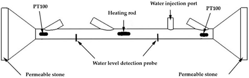
FIGURE 1. Sensing structure of thermal seepage sensor.
According to the heat transfer principle, the relationship between the heat Q taken away by the fluid per unit time, the temperature difference ΔT between the heating rod and the fluid, and the flow velocity v of the fluid can be expressed by the following formula:
In the formula, ρ represents the density of the fluid; k1, k2, and k3 are constants in the same fluid.
If the cross section of the thin round tube structure of the sensor is A, its mass flow rate is qm = ρvA. When measuring the seepage in rock and soil, the ceramic heating rod with the resistance of Rj is heated by the current of Ij to heat the fluid in the thin tube. After a period of time, it will reach an equilibrium state. At this time, the heat generated by the heating rod per unit time is the same as the heat carried away by the surrounding fluid by the heating rod, that is, Q=Ij2Rj2, so there is a functional relationship between the mass flow qm and Q/△T, which can be expressed by the following formula (Munaf et al., 1993):
From equation (Ghafoori et al., 2020), it can be concluded that the seepage flow can be obtained by measuring temperature difference ΔT of the fluid at both ends of the thin round tube through the sensor when the current Ij flowing through the heating rod is constant.
Temperature changes can affect the physical and chemical parameters of water and soil, thereby affecting the distribution of seepage fields in the soil. The parameters closely related to seepage field and temperature field in rock and soil include porosity, specific heat capacity, heat conduction, thermal conductivity, and other parameters. With the increase of temperature, the viscosity of water decreases and the permeability coefficient increases. Due to the small power of the heating rod in this paper, the effect of temperature change on the seepage was ignored in the experiments and measurements (Huang et al., 2021).
Sensor Design
Structural Design of Thermal Seepage Sensor
The sensor structure shown in Figure 1 mainly includes a water filtration structure made of permeable stone, a heating rod, and a PT100 temperature measurement instrument (Aranzabal et al., 2019). A funnel-shaped water collection device was designed at both ends of the sensor to increase the flow in the thin tube. When the seepage in rock and soil flows into the sensor from left to right or from right to left, it first passes through the upstream PT100 platinum resistance temperature sensor to collect the initial water temperature flowing into the thin tube, and then the seepage flows through the heating rod to be heated. The fluid then flows through the downstream PT100 platinum resistance temperature sensor. The temperature measured downstream is the water temperature after it is heated by the heating rod. At this time, if the heating power of the heating rod is kept constant, the greater the seepage flow rate in the thin round tube, the smaller the temperature difference measured by the upstream and downstream platinum resistance PT100 sensors, and vice versa.
At present, distributed optical fiber temperature measurement technology is commonly used in seepage flow measurement in rock and soil. The temperature sensitivity of Brillouin method based on distributed optical fiber temperature measurement technology in practical projects is about ±4°C, and which in the laboratory is generally less than ±2°C, Raman method can reach ±0.5°C. However, the temperature measurement accuracy of the platinum resistance PT100 sensors can reach ±0.1°C. The system experimental tests are all measured at room temperature, the influence of the ambient temperature on its measurement can be ignored since the temperature difference between the two PT100 is measured.
Because seepage flows in rock and soil are very small, the smaller the diameter of the thin tube, the better the effect. An alumina ceramic heating rod with many advantages was used in the design, the power of the heating rod is 5 W under the power supply voltage of 5 V. It has been proved by experiments that the liquid in the thin tube will not produce air bubbles under this power value, so that it has little influence on the measurement results.
Principle of Water Level Detection
In Figure 1, two thin probes were designed and inserted perpendicular to the inner wall of the thin tube of the fluid meter. If the thin tube is filled with water, the water resistance between the two probes is a fixed value; if the thin tube is not filled with water, the resistance between the two probes becomes larger. During the actual experimental measurements, when the thin tube was filled with water, the resistance between the two probes was about 70 kΩ. A 70 kΩ matching resistance was selected in series with the two ends of the water level detection probe, and power was applied to both ends to measure the voltage on the matching resistance. The water level in the capillary could be easily determined.
Selection of Permeable Materials
The rock—soil seepage measurement sensor based on heat transfer designed in this paper needs to be placed in the rock and soil for actual applied measurements. Because the fine particles present in seepage in rock and soil can easily block the sensor, the sensor needs permeable materials to filter the seepage. At present, the commonly used water-permeable materials include fibrous materials, activated carbon, diatomaceous earth, porous ceramics, etc. The sensor needs to be placed in the rock and soil when used, so the water-permeable material needs to have good mechanical properties and stable chemical properties. Compared with other water-permeable materials such as fibrous materials, activated carbon, etc., porous ceramic materials have many advantages; for example, they can be used in high temperature, high pressure, acid, alkali, and organic environments; their pore structures and porosity can be controlled; their service life is long. The product has good regeneration performance, so porous ceramic materials were used as the water-permeable material in this design.
Structural Design of Seepage Meter
Because the sensor, heating rod, and porous ceramics are placed on the seepage sensor, high mechanical strength, and strict waterproofing are required. After repeated experiments, the structure shown in Figure 2A and 3D printing were used to form one piece to achieve a precise size and good waterproof performance. 3D printing uses transparent resin raw materials, which were convenient for observing the position and seepage of the temperature probe and heating rod in the thin tube during the experiment. The diameters of the funnel on both sides are 40 cm, and the diameter of the thin tube in the middle is 6 cm. There are tubular protrusions on the thin tube. In order to place the sensor in them easily and to waterproof them, the cylindrical housing and back cover of the sensor were designed at the same time, and the measuring structure was also placed in it by 3D printing. Its appearance is shown in Figure 2B. A physical map of the seepage sensor is shown in Figure 2C.
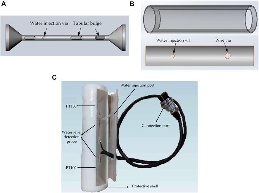
FIGURE 2. Seepage sensor (A) the structure of the sensor; (B) Seepage meter protective shell and packaging cover; (C) Physical image of seepage meter sensor.
The platinum resistance temperature probe, heating rod, and water level measurement probe were installed and wrapped with a heat-shrinkable tube. At the same time, they were filled with silica gel for waterproofing. In order to facilitate the observation of seepage, the structure of the sensor shell and the thin round tube funnel were made from translucent materials.
Thermal Seepage Sensor Signal Acquisition and Processing System
Thermal Seepage Sensor Temperature Measurement Circuit Design
The principle of the temperature measurement is shown in Figure 3. The 1 mA constant current source generating circuit provides a constant current for the platinum resistance temperature measurement circuit. The temperature measurement circuit converts the resistance change in the platinum resistance into a voltage value change, which is then amplified by a precision amplifier circuit. The signal acquisition unit converts the collected temperature voltage value into a digital quantity and sends it to the microprocessor by A/D converter, and finally, the calculated temperature value is sent by the microprocessor through the serial port to the upper computer. The platinum resistance temperature measurement circuit is shown in Figure 4.
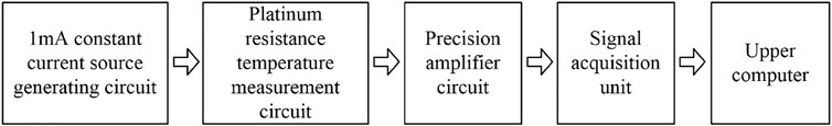
FIGURE 3. Block diagram of the temperature measurement principle.
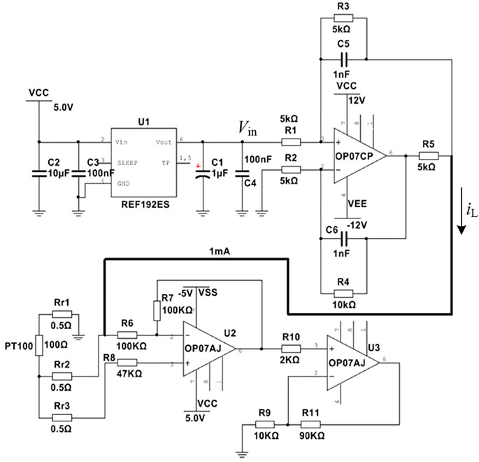
FIGURE 4. The platinum resistance temperature measurement circuit.
The REF192ES in Figure 4 is a voltage reference chip used to generate a 2.5 V reference voltage. The 1 mA constant current source generation circuit uses the Howland operational amplifier current source structure. The constant current source circuit uses a low-noise and high-precision OP07CP operational amplifier, which uses a dual power supply. In this design, R1=R2=5 kΩ, R3=R5=5kΩ, R4=10kΩ; in order to ensure the accuracy of the constant current source, the resistance selects a BWL-EE type resistor with an accuracy of 0.1% and a temperature drift of 5 ppm. The Howland operational amplifier current source structure can be obtained:
Signal Acquisition Unit Design
The signal acquisition unit of the thermal seepage sensor is responsible for the acquisition of measurement process information and the transmission of data. Taking into account the needs of the measurement system, cost, power consumption, and other factors, it adopts STMicroelectronics’ STM32F103 series 32-bit MCU STM32F103ZET6 chip and its internal with an ARM Cortex-M3 core, which can use registers and library files for programming and which is very simple and easy to transplant. The signal acquisition program mainly completes the functions of water level detection, voltage value detection at both ends of the platinum resistor, temperature calculation, heating rod on–off control, flow calculation, results display and data transmission. The system program flow chart is shown in Figure 5.
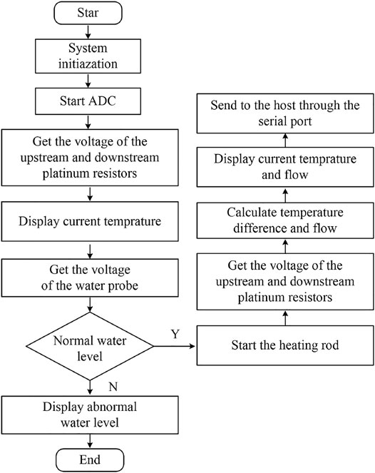
FIGURE 5. System program flow chart.
Portable Geotechnical Seepage Measuring Instrument
For the portable application of the instrument, the designed and implemented thermal seepage measuring instrument is shown in Figure 6. It uses a 10.2-inch portable instrument waterproof box. The power supply, measurement circuit and control circuit are all placed inside the box. The panel is designed with various function buttons, a touch screen and a sensor card slot. The realized portable thermal seepage measuring instrument is powerful, the VGUS graphical design interface is easy to use, the VGUS built-in virtual serial screen can be used to easily design the display interface, display controls, touch functions, etc., and it also has a curve control to display the data as a curve.
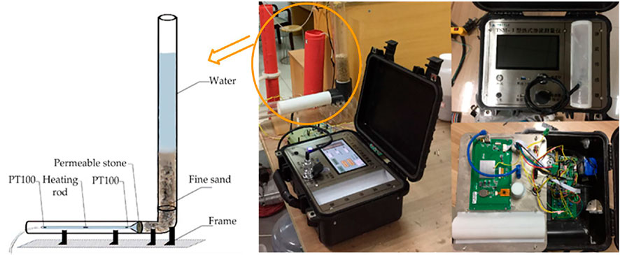
FIGURE 6. The overall structure of the portable seepage meter.
In order to obtain the real situation of seepage in rock and soil, and to simulate the conditions and environment of seepage in rock and soil more realistically, the experimental platform built shown in Figure 6 was designed. It was connected by a transparent tube with a length of 110 cm and a diameter of 40 cm, an elbow with a DN40 caliber, and a transparent tube with a horizontal length of 50 cm and the diameter of the thin tube in the middle is 6 cm. The bottom plate adopted thick acrylic for counterweight. The schematic diagram of the experimental device in the circle is shown on the left in Figure 6. The horizontally placed transparent tube was the thin tube funnel part of the thermal percolation meter. Because the seepage direction was determined, the experimental device in the figure only used unidirectional water-permeable ceramics. The joints of the whole device were sealed and waterproofed with waterproof glue (Ma et al., 2014).
Experimental Measurement
Experiment on the Relationship Between Flow Rate and Temperature Change
Soil structures in different regions are different, and compositions of rock and soil are complex. Most rock and soil materials are composed of coarse sand or loose deposits with large particle diameters. According to Engineering Classification Standard of Soil (GB/T50145-2007), the particle groups of soil are divided according to diameter. The particle size and permeability coefficient reference values of various soils are shown in Table 1. The experiments were carried out using clay, powder, fine sand, moderate sand and coarse sand. The diameter of the clay was about 0.003 mm, and the permeability coefficient was 0.3 m/d, the diameter of powder was about 0.006 mm, and the permeability coefficient was 0.8 m/d, the water flow velocity in the experiment was about 4–5 drops/s; the diameter of fine sand particles was about 0.1 mm, and the permeability coefficient was 3 m/d, the flow rate is about 17–18 drops/s. In the above process, that each drop of water was about 0.05 ml based on calibration and repeated experiments (Abdullah et al., 2020).
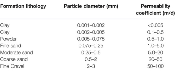
TABLE 1. Reference values of permeability coefficients of different diameter particles.
The restrictor valve was used to adjust the flow rate of water to simulate the seepage flows of different rock and soil materials in the experiment. Therefore, a restrictor valve was installed at the water outlet end of the thin tube of the test device. By adjusting the restrictor valve, the flow rate of water droplets can be controlled per second: 1 drop, 2 drops, 4 drops per second, etc. After repeated experiments under the same conditions, the volume of each drop of water could be considered constant, so the volume of 100 drops of water flowing out of the infusion device measured by a graduated cylinder was about 5 ml, and the volume of each drop of water under the same experimental conditions was about 0.05 ml. Figure 7 shows the temperature difference curves measured at different flow rates.
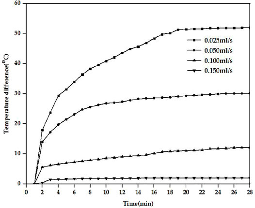
FIGURE 7. The relationship between different flow rates and corresponding temperature differences.
It can be seen from the Figure 7 that under different flow rate conditions, the temperature differences changed the most from about 0–4 min, the temperature differences for the PT100 at both ends of the seepage meter continued to increase, and the temperature differences changed slowly after 4 min. When the seepage flow rate was 0.025 ml/s, the temperature difference tended to remain unchanged at about 52°C after 20 min. When the seepage flow rate was 0.05 ml/s, the temperature difference tended to remain unchanged at about 30°C after 20 min. When the seepage flow rate was 0.10 ml/s, the temperature difference stabilized after 20 min at 12°C. When the seepage flow rate was 0.15 ml/s, the temperature difference stabilized after 4 min at 2°C.
In the experiments, if the temperature difference change rate within 5 min was less than 0.1°C/min, the temperature could be called the characteristic value Tt of the sample. Table 2 shows the data of the temperature characteristics and heating times under different flow rates for the silty sand, it can be determined that as the flow rate increased, Tt was decreased linearly, and the heating time became shorter. Tt and the seepage flow rate can be polynomially fitted to obtain the relational expression, where the ordinate y represents the temperature of the temperature difference of the value in degrees Celsius (°C), and the abscissa x represents the percolation flow rate in milliliters per second (ml/s), the goodness of fit of the curve is 0.988.
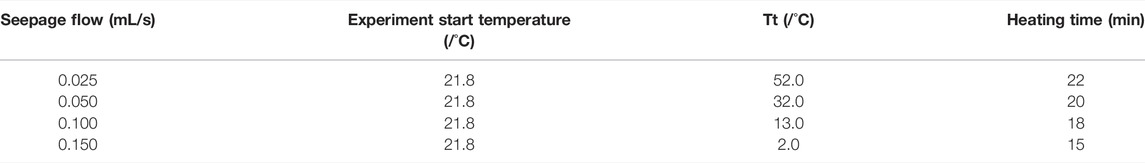
TABLE 2. Measured temperature characteristics of seepage sensor under different seepage flows.
Seepage Measurement Experiment
To carry out the seepage measurement experiment conducted in this study, put equal volumes of clay, powder, fine sand, and coarse sand into a round pipe with a permeable ceramic backing, and measure its actual penetration according to the constant head permeability test. Add an equal volume of water, measure the temperature difference determined by the platinum resistance at the upstream and downstream ends of the thin round tube, and obtain the output characteristic curves of the clay, powder, fine sand and coarse sand shown in Figure 8.
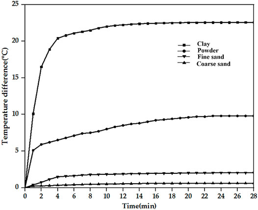
FIGURE 8. Corresponding temperature difference curves of different diameter particles.
It can be concluded from Figure 8 that for the different rock soils used in the experiments, the temperature differences rose significantly in the first 4 min, and then increased slowly until they stabilized. After the system was powered on, the heating rod began to heat, and the temperature differences measured by the upstream and downstream PT100 platinum resistors increased rapidly, and after a period of time, the temperature differences increased slowly until they stabilized.
The characteristic temperature measured by the experiment is brought into the formula (Leifer et al., 2011), and the flow rate can be obtained, Table 3 shows the data of temperature characteristics, the measured seepage flow and the calculated seepage flow under different geotechnical condition, the relative error is defined as the absolute value of the calculated seepage flow minus the measured value divided by the measured value, and which are all within 3%.
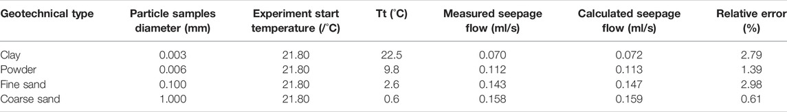
TABLE 3. Temperature characteristics and seepage flow under different geotechnical conditions.
Conclusion
Based on the basic principles of heat transfer in seepage measurement, a thermal seepage sensor was proposed, and the fabrication has been completed. The following conclusions were drawn based on the theoretical analysis and experimental results.
(1) The structure of the sensor is composed of a thin tube in the middle and two funnels connected at both ends of the thin tube. The small end of the funnel is fixed to the end of the thin tube and communicates with the thin tube. The heating rod is controlled inside the thin tube, the two ends of the thin tube are equipped with temperature sensors, and the probe needle is arranged in the middle of the thin tube.
(2) An experimental platform for thermal seepage measurement was built, and experiments on flow velocity and temperature changes, seepage meter calibration experiments, and rock and soil seepage measurement experiments were carried out. The temperature characteristic values of the silty sand with seepage flow of 0.025 ml/s, 0.050 ml/s, 0.100 ml/s and 0.150 ml/s are obtained by experiments, and measured temperature characteristic values are 52.0, 30.0, 12.0 and 2.0°C, respectively. Formulas for the characteristic values of seepage flow and temperature are presented.
(3) Based on the same experimental method, the temperature characteristic values and seepage flow of clay, powder, fine sand, and coarse sand were measured. The seepage flow rate under different sample conditions were calculated based on the relationship formula between seepage flow rate and temperature characteristic, the errors between the experimental value and the calculated value are within 3%.
Our future work will focus on the study of the influence on the seepage flow rate under different heating power conditions is extreme for the same sample. Secondly, we will expand the types of experimental samples to obtain more abundant experimental data.
Data Availability Statement
The original contributions presented in the study are included in the article/supplementary material, further inquiries can be directed to the corresponding author.
Author Contributions
XW wrote the manuscript. JC and RT performed the experiments. QL proposed the idea and guided the experiments and writing.
Funding
The research was supported by The National Key Research and Development Program of China (2017YFC0804604), and open fund of Key Laboratory for Technology in Rural Water Management of Zhejiang Province.
Conflict of Interest
The authors declare that the research was conducted in the absence of any commercial or financial relationships that could be construed as a potential conflict of interest.
Publisher’s Note
All claims expressed in this article are solely those of the authors and do not necessarily represent those of their affiliated organizations, or those of the publisher, the editors and the reviewers. Any product that may be evaluated in this article, or claim that may be made by its manufacturer, is not guaranteed or endorsed by the publisher.
References
Abdullah, T. O., Ali, S. S., Al-Ansari, N. A., Knutsson, S., and Laue, J. (2020). Magnitude and Direction of Groundwater Seepage Velocity in Different Soil and Rock Materials. Eng 12, 242–253. doi:10.4236/eng.2020.124020
Aranzabal, N., Martos, J., Steger, H., Blum, P., and Soret, J. (2019). Temperature Measurements along a Vertical Borehole Heat Exchanger: a Method Comparison. Renew. Energy 143, 1247–1258. doi:10.1016/j.renene.2019.05.092
Bolève, A., Janod, F., Revil, A., Lafon, A., and Fry, J. J. (2011). Localization and Guantification of Leakages in Dams Using Time-lapse Self-potential Measurements Associated with Salt Tracer Injection. J. Hydrol. 403, 242–252. doi:10.1016/j.jhydrol.2011.04.008
Ballard, S. (1996). The In Situ Permeable Flow Sensor: A Ground-Water Flow Velocity Meter. Groundwater 34, 231–240. doi:10.1111/j.1745-6584.1996.tb01883.x
Chen, J., Xiong, F., Zheng, J., Ge, Q., and Cheng, F. (2019). Calibration Experiment for Seepage Monitoring Using Fiber Bragg Grating Hydrothermal Cycling Integration System. Geotech. Test. J. 42, 2017017. doi:10.1520/gtj20170179
Dusabemariya, C., Jiang, F., Qian, W., Faruwa, A. R., Bagaragaza, R., and Ali, M. (2021). Water Seepage Detection Using Resistivity Method Around a Pumped Storage Power Station in China. J. Appl. Geophys. 188, 104320. doi:10.1016/j.jappgeo.2021.104320
Fang, X., Xiong, F., and Chen, J. (2019). An Experimental Study on Fiber Bragg Grating-point Heat Source Integration System for Seepage Monitoring. IEEE Sens. J. 19, 12346. doi:10.1109/jsen.2019.2937155
Galagedara, L. W., Parkin, G. W., and Redman, J. D. (2003). An Analysis of the Ground-Penetrating Radar Direct Ground Wave Method for Soil Water Content Measurement. Hydrol. Process. 17, 3615–3628. doi:10.1002/hyp.1351
Ghafoori, Y., Maček, M., Vidmar, A., Říha, J., and Kryžanowski, A. (2020). Analysis of Seepage in a Laboratory Scaled Model Using Passive Optical Fiber Distributed Temperature Sensor. Water 12, 367. doi:10.3390/w12020367
He, F., Chen, J., and Xiong, F. (2021). Comparison of the Seepage Monitoring Results between Saturated and Unsaturated State Using Point Heat Source Method. KSCE J. Civ. Eng. 25, 4567. doi:10.1007/s12205-021-1635-z
Huang, Y.-H., Yang, S.-Q., and Teng, S.-Y. (2021). Temperature Dependence of the Permeability of Sandstone under Loading and Unloading Conditions of Confining Pressure. Math. Geosci. 53, 551–570. doi:10.1007/s11004-020-09860-7
Leifer, I., Luyendyk, B. P., and Culling, D. (2011). Active Multibeam Sonar‐derived Bubble Plume Fluxes and Dynamics. J. Acoust. Soc. Am. 129, 2653. doi:10.1121/1.3588852
Ma, D., Miao, X. X., Jiang, G. H., Bai, H. B., and Chen, Z. Q. (2014). An Experimental Investigation of Permeability Measurement of Water Flow in Crushed Rocks. Transp. Porous Med. 105, 571–595. doi:10.1007/s11242-014-0385-5
Munaf, D., Wineman, A. S., Rajagopal, K. R., and Lee, D. W. (1993). A Boundary Value Problem in Groundwater Motion Analysis - Comparison of Predictions Based on Darcy's Law and the Continuum Theory of Mixtures. Math. Models Methods Appl. Sci. 03, 231–248. doi:10.1142/s0218202593000138
Panthulu, T. V., Krishnaiah, C., and Shirke, J. M. (2001). Detection of Seepage Paths in Earth Dams Using Self-Potential and Electrical Resistivity Methods. Eng. Geol. 59, 281–295. doi:10.1016/S0013-7952(00)00082-X
Rakesh, N. S., Ahmed, A., Joseph, J., Aouti, R. S., and Ananthasuresh, G. K. (2020). Analysis of Heat Paths in Dual-Probe-Heat-Pulse Soil-Moisture Sensors for Improved Performance. Sens. Actuat. A-Phys. 318, 112520. doi:10.1016/j.sna.2020.112520
Rosenberry, D. O., Duque, C., and Lee, D. R. (2020). History and Evolution of Seepage Meters for Quantifying Flow between Groundwater and Surface Water: Part 1 - Freshwater Settings. Earth-Science Rev. 204, 103167. doi:10.1016/j.earscirev.2020.103167
Rosenberry, D. O., and Morin, R. H. (2004). Use of an Electromagnetic Seepage Meter to Investigate Temporal Variability in Lake Seepage. Groundwater 42, 68–77. doi:10.1111/j.1745-6584.2004.tb02451.x
Selker, F., and Selker, J. S. (2014). Flume Testing of Underwater Seep Detection Using Temperature Sensing on or Just below the Surface of Sand or Gravel Sediments. Water Resour. Res. 50, 4530–4534. doi:10.1002/2014wr015257
Shen, X., Zhang, M., Zhang, J., and Yang, H. (2015). Development on Measuring Devicefor Seepage Coefficient of Super-size Coarse-Grained Soil. J. Coast. Res. 73, 375–379. doi:10.2112/si73-066.1
Skinner, A. J., and Lambert, M. F. (2009). Evaluation of a Warm-Thermistor Flow Sensor for Use in Automatic Seepage Meters. IEEE Sensors J. 9, 1058–1067. doi:10.1109/jsen.2009.2024056
Solder, J. E., Gilmore, T. E., Genereux, D. P., and Solomon, D. K. (2016). A Tube Seepage Meter for In Situ Measurement of Seepage Rate and Groundwater Sampling. Groundwater 54, 588–595. doi:10.1111/gwat.12388
Su, H., Tian, S., Kang, Y., Xie, W., and Chen, J. (2017). Monitoring Water Seepage Velocity in Dikes Using Distributed Optical Fiber Temperature Sensors. Automation Constr. 76, 71–84. doi:10.1016/j.autcon.2017.01.013
Keywords: seepage measurement, heat transfer, small flow rate, online monitoring, geological monitoring
Citation: Wu X, Cui J, Tong R and Li Q (2022) Experimental Research and Instrument Design of Seepage Measurement in Rock and Soil Based on Heat Transfer. Front. Earth Sci. 10:917561. doi: 10.3389/feart.2022.917561
Received: 11 April 2022; Accepted: 31 May 2022;
Published: 17 June 2022.
Edited by:
Fengqiang Gong, Southeast University, ChinaReviewed by:
Annan Jiang, Dalian Maritime University, ChinaLuzhen Wang, Yancheng Institute of Technology, China
Copyright © 2022 Wu, Cui, Tong and Li. This is an open-access article distributed under the terms of the Creative Commons Attribution License (CC BY). The use, distribution or reproduction in other forums is permitted, provided the original author(s) and the copyright owner(s) are credited and that the original publication in this journal is cited, in accordance with accepted academic practice. No use, distribution or reproduction is permitted which does not comply with these terms.
*Correspondence: Qing Li, bHFfY2psdUAxNjMuY29t