 Ming Zhang
 Baoli Zhao3
- 1College of Petroleum Engineering, Xi’an Shiyou University, Xi’an, China
- 2Shaanxi Cooperative Innovation Center of Unconventional Oil and Gas Exploration and Development, Xi’an Shiyou University, Xi’an, China
- 3No. 2 Gas Production Plant, PetroChina Changqing Oilfield Company, Yulin, China
By employing molecular dynamic (MD) and density functional theory (DFT) calculations, the adsorptions of CO2, N2, CO, H2S, CH4, and H2O onto methane hydrate (MH) surface are compared in this work. The methane hydrate planes of (001) and (110) and various cleaving sites are compared with cleavage energies. MH(001) has more tendency to form when compared with MH(110) in thermodynamics. Two different terminations of MH(001) surfaces are compared, and MH(001)-I (terminated with CH4+H2O) leads to more negative adsorption energies when compared with MH(001)-II (terminated with H2O only). The priority sequence of the adsorptions can be queued as: H2O > H2S > CO2 > N2 > CH4 > CO. Namely, CO2, N2, and H2S have potential to replace CH4 in methane hydrate. The interfacial hydrogen bond and electronic interactions are clarified for the adsorptions of CO2, N2, and H2S. The hydrogen bonds tend to form between O-H atom pairs of CO2-H2O, N-H atom pairs of N2-H2O, and S-H and H-O atom pairs of H2S-H2O, respectively. The bonds are mainly contributed from the dispersion interaction between the O-2p in CO2 and H-1s in H2O, N-2p in N2 and H-1s in H2O, S-3p in H2S and H-1s in H2O, and H-1s in H2S and O-2p in H2O, respectively.
1 Introduction
In the last few decades, natural gas clathrate, especially methane hydrate (MH), has attracted attention from a wide range of academic communities (Kvenvolden, 1988; Sloan, 2003; Walsh et al., 2009; Lunt et al., 2011). Methane hydrates are ice-like inclusion compounds that are composed of water (H2O) and methane (CH4) molecules, and CH4 guest molecules are encapsulated in the hydrogen-bonded water cages (Sloan, 2003). Compared with other fossil fuels, methane hydrate generates lower CO2 emissions per unit of energy, which makes it a promising energy source to mitigate global warming (Lunt et al., 2011; Phrampus and Hornbach, 2012).
Up to now, nine different polymorphs are reported for MH’s structures, which includes three cubic (sI, sII, and sIII), one hexagonal (sH), one orthorhombic (sIV), two monoclinic (sV and sVI) and two tetragonal (sT and sK) structures (Cao et al., 2017; Huang et al., 2018). Among these polymorphs, Cubic sI structure (sI-MH) predominates in the Earth’s natural environments (Sloan, 2003). Under room temperature, structure type sI is stable below 120 MPa (Shu et al., 2011). Eight water cages (two 512 small cages and six 51262 large cages) are contained in sI-MH, in which eight methane molecules are trapped, and the ideal H2O:CH4 ratio is 5.75. The 512 small cage can be regarded as formed with water molecules in the positions of 12 pentagons, while the 51262 large cage can be regarded as formed with water molecules in the positions of 12 pentagons and two hexagons (Figure 1).
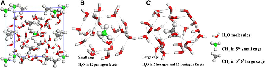
FIGURE 1. Atomic structure of cubic sI-MH (A). The spheres with white, green (grey), and red colors denote H, C, and O atoms, and C atoms in green and grey depict the carbon atoms of CH4 in 512 small water cage (B) and 51262 large water cage (C), respectively.
Compared with conventional natural gas sources, MH’s exploitation is more challenging. Dissociating or untrapping CH4 molecules from H2O cages is the fundamental problem. Thermal stimulation and depressurization are commonly proposed as exploitation techniques (Chong et al., 2016). However, they change the reservoir’s conditions, which makes it no longer thermodynamically stable, which facilitates dissociating CH4. Inhibitor injection usually employs ethylene glycol (EG) as an inhibitor. However, the inhibitor’s required concentration is as high as around 30 wt.% (Chong et al., 2016). In recent years, replacing CH4 with CO2 (and/or N2) in methane hydrate is also proposed as an encouraging avenue (Cha et al., 2015; Zhang et al., 2017a; Zhang et al., 2017b; Okwananke et al., 2018; Matsui et al., 2020). In the replacing process, the adsorption of CO2 (N2) onto MH surface can be regarded as the first step. Meanwhile, various small gas molecules might also compete in the adsorption. For example, CO and H2S gases are commonly associated with MH reservoirs, replacing CH4 from MH with CO2 (or N2) is potentially affected by the adsorptions of CO and H2S. Meanwhile, the condensation of MH can be viewed as an adverse process of CH4 dissociation, which can be also regarded as the adsorptions of CH4 and H2O onto the MH surface. Therefore, the competition derived from these small gas molecules’ adsorptions should be considered. The interfacial bonding mechanism between CO2, N2 and MH surface is also interesting to be clarified. Unfortunately, the correlated content has been insufficiently reported in the literature.
In this work, by employing MD and DFT methods, the adsorptions of several kinds of gas molecules (i.e., CO2, N2, CO, H2S, CH4, and H2O) onto sI-MH surface are investigated. Their adsorption priorities are confirmed based on the energetic data and the interfacial electronic interactions are also discussed.
2 Methodology and details
2.1 Computation parameters
In the present work, MD and DFT calculations are conducted by employing FORCITE and CASTEP (Clark et al., 2005) codes in the Materials Studio package. The forcefield of COMPASS (Sun, 1998; McQuaid et al., 2004) and pseudopotential of GGA-PBE are employed in both calculations, respectively. The atom cores and valence electrons of H 1s1, C 2s22p2, N 2s22p3, O 2s22p4, S 3s23p4, and cutoff energy of 450 eV and k-points spacing around 0.03 Å−1 are adopted. To better describe the inter-atomic bonding effect, the van der Waals dispersion corrections (DFT-D, TS scheme (Tkatchenko and Scheffler, 2009), sR = 0.94 and d = 20) are deployed in all DFT of the calculations. The parameters C6, R0, α are listed in Table 1.

TABLE 1. Parameters employed in the DFT-D TS scheme.
2.2 Calculation of bulk methane hydrate
The cubic cell of bulk sI-MH (Figure 1) contains 46 H2O and eight CH4 molecules. Its oxygen lattice has the space group of Pm-3n (Kirchner et al., 2004). After DFT geometry optimization, the lattice parameters of sI-MH unit cell and diatomic lengths are summarized in Table 2. Some previous experimental and theoretical data are also listed as references. Our results agree well with these data.

TABLE 2. Calculated results and previous data of sI-MH unit cell.
2.3 Cleavage energy and surface models
Under the theorem of thermodynamics, for any condensed materials, their facet (or plane) with minimum excess energy tends to be the surface contacting with other matters (e.g., air, liquid, vacuum, or other condensed phases). In the present work, cleavage energy is employed to determine the energetically-favored surface of sI-MH. The low-index planes of the methane hydrate surface are mentioned in the literature, such as (001) (Hu et al., 2021a; Liao et al., 2022) and (110) (Liang et al., 2011; Cox et al., 2018). Consequently, both planes are specifically discussed in the present work.
Two different cleaving planes (i.e., (001) and (110) planes) are considered (as shown in Figure 2). For cleaving plane (001), three sites (denoted as Site I, II and III) are compared; while for cleaving plane (110), two sites (denoted as Site IV and V) are examined.
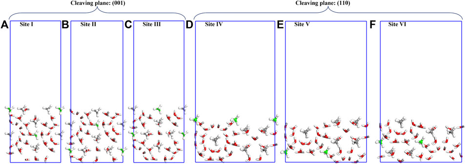
FIGURE 2. Cleaved slabs along (001) and (110) planes of sI-MH with 20Å vacuum in depth: (A–F) are cleaved slabs along different sites (Sites-I to Site-VI). The white, grey (green), and red spheres denote H, C, and O atoms, and CH4 with grey and green C atoms are from large and small water cages, respectively.
The cleavage energy (Ecl) can be estimated as:
where A denotes the surface area,
The cleavage energies (Ecl) are calculated as shown in Table 3. Cleaving along (001) at Site-I requires the lowest cleavage energy. Consequently, bulk methane hydrate is more likely to be cleaved in this case. However, cleaving the bulk sI-MH cell along (001) at Site-I will simultaneously generate two surfaces with distinct terminations. Namely, the top and bottom surfaces depicted in Figure 2A will be created simultaneously. For both surfaces, one is terminated with H2O+CH4 and the other is terminated with H2O only. For simplicity, both surfaces are denoted as MH(001)-I and MH(001)-II, respectively. It is difficult to determine their energetic priorities. Therefore, the both surfaces are considered in following interfacial calculations.
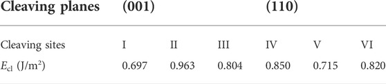
TABLE 3. Calculated cleavage energies (Ecl) along (001) and (110) planes of sI-MH.
The MH(001)-I and MH(001)-II surface models are established with areas of 11.31 × 11.31 Å2. A vacuum layer (20Å in thickness) is inserted to avoid the imaginary interaction between the top and bottom sides. The same number of molecules (46 H2O and 8CH4) are included in both surface models.
First, the surface models are fully relaxed within DFT-D frame. During the relaxations, the inner atoms are fully constrained to mimic the bulk-like interior. To determine optimal constraint conditions, different constraints are compared for both surface models (as shown in Figure 3).
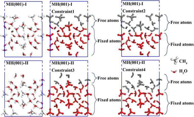
FIGURE 3. Constraint conditions of MH(001)-I and MH(001)-II surface models.
The energies of initial and optimized models are listed in Table 4. According to our calculated results, the energy deviation between optimized models with Constraint1 and Constraint2 conditions is merely around -0.6 eV. Likewise, the energy deviation between Constraint3 and Constraint4 conditions is also less than −0.5 eV. Consequently, it is evidenced that, for surface models MH(001)-I and MH001)-II, Constraint2 and Constraint4 are adequate to guarantee the calculations’ accuracy. MH(110)-I and MH(001)-II with Constraint2 and Constraint4 are employed as substrates in the following adsorption simulations (interface models).
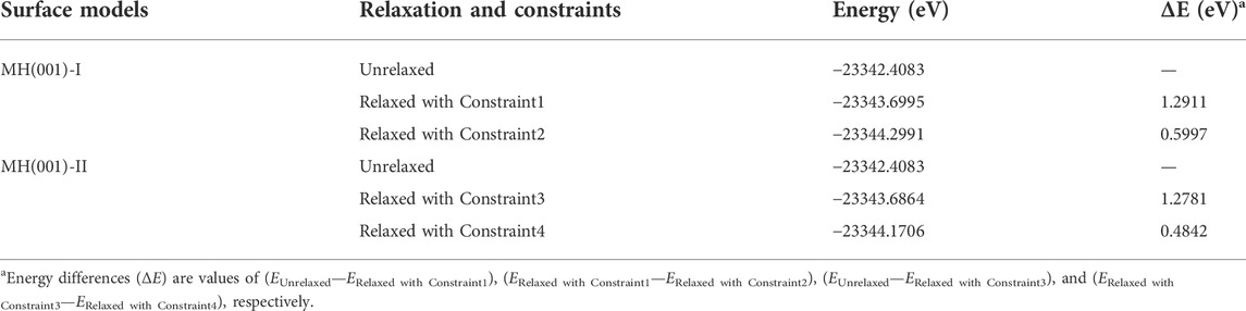
TABLE 4. Calculated energy differences (ΔE) between initial and optimized surface models of sI-MH.
2.4 Interface models and adsorption simulations
By arbitrarily putting single molecule (CO2, N2, CO, H2S, CH4 and H2O) over MH(110)-I and MH(110)-II surfaces, the initial distance between the molecule and surface is roughly 10 Å, and 12 interface models are established. These initial models (Figure 4) are treated as starting points of the adsorption processes.
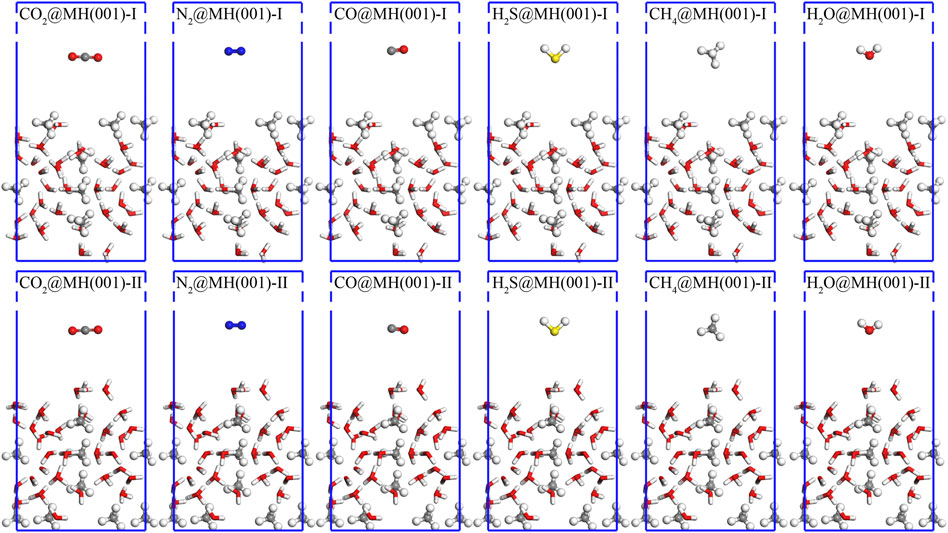
FIGURE 4. Initial interface models for the adsorptions of CO2, N2, CO, H2S, CH4, and H2O over MH(001)-I and MH(001)-II substrates. The white, grey (green), red, blue, and yellow spheres denote H, C, O, N, and S atoms, respectively.
For the initial interface models, MD geometry optimization is first implemented to achieve an intermediate configuration. On this basis, DFT-D relaxation is continued to reach the final configuration. The final relaxed models are treated as the equilibrium states of adsorption processes.
3 Results and discussion
3.1 Equilibrium model and adsorption energies
By sequentially conducting geometry optimizations with MD and DFT-D methods, the final equilibrium interface models are as shown in Figure 5.
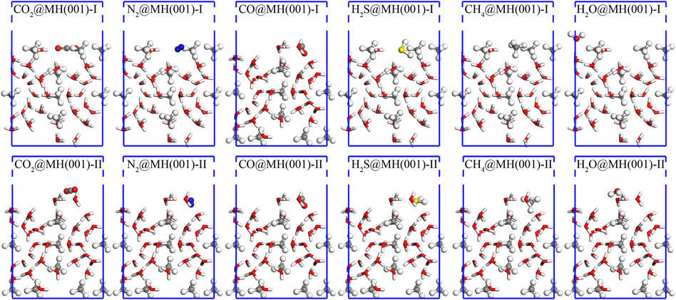
FIGURE 5. Final equilibrium interface models for the adsorptions of CO2, N2, CO, H2S, CH4, and H2O over MH(001)-I and MH(001)-II substrates. The white, grey (green), red, blue, and yellow spheres denote H, C, O, N, and S atoms, respectively.
Based on these final models, the adsorption energies (Ead) can be ascertained as (Zhu et al., 2017):
where Efinal interface, Esurface, and Emolecule denote the total energies of final interface slab, surface slab, and adsorbed gas molecules. The calculated adsorption energies (Ead) are listed in Table 5.
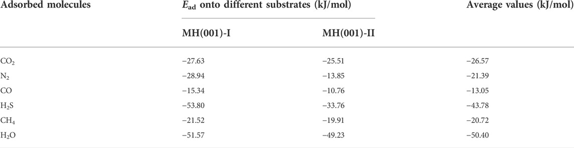
TABLE 5. Calculated adsorption energies (Ead) of CO2, N2, CO, H2S, CH4, and H2O onto MH(001)-I and MH(001)-II substrates.
The previous Ead data of these six molecules are hardly retrieved. The adsorption energy of H2O on the ice Ih basal plane were calculated around -59 kJ/mol (Thierfelder et al., 2006). By using the MD method, the adsorption energy of a single water molecule during MH’s formation could be as high as −84.14 kJ/mol (Cox et al., 2018). The adsorption energies of single CH4 and CO2 into hydrate cage cavities were estimated as 46.31 kJ/mol and 36.66 kJ/mol with DFT method, respectively. The adsorption energy was estimated as large as −61.48 kJ/mol the adsorption energy of amino acids over (001) surface by employing DFT calculations (Hu et al., 2021b). These data are close to our results. Therefore, our results are reasonable and acceptable.
First, the adsorption energies for the six different molecules are all negative. This means that these adsorptions are all exothermal and spontaneous processes onto MH(001) substrate.
Second, a greater Ead value implies a larger heat release for the adsorption process. Therefore, a greater Ead value implies a stronger driving force to facilitate the adsorption’s spontaneous occurrence. Consequently, the priority order of these adsorption processes can be queued as: H2O > H2S > CO2 > N2 > CH4 > CO. The adsorptions of H2O and CH4 can be regarded as the condensation of MH. The condensation process of H2O is most prevalent. Importantly, the adsorptions of H2S, CO2 and N2 are more privileged when compared with the condensation of CH4, This implies that the molecules H2S, CO2 and N2 have potential to be employed to replace CH4 in MH. Meanwhile, the CO molecule has the least tendency to adhere onto MH(001) surface, and CH4 will be hardly replaced with CO.
3.2 Interfacial configuration and electronic interaction
3.2.1 Interfacial diatomic distance
Our calculation results demonstrate that the molecules of CO2, N2, and H2S can spontaneously adhere onto MH(001)-I surface. Their equilibrium atomic configurations are illustrated as Figure 5 and Figure 6.
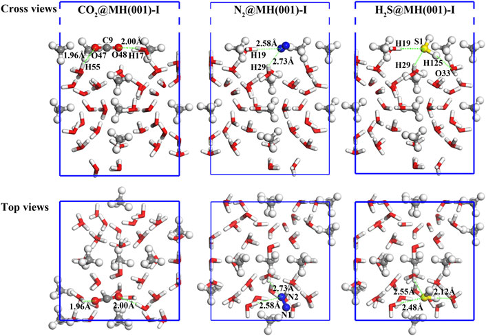
FIGURE 6. Final adsorption models of CO2, N2, and H2S molecules, the green-dashed lines denote the interfacial bonds, and spheres with white, red, blue, yellow, and grey colors denote H, O, N, S, and C atoms, respectively.
The absorbed molecules have closer distance to the H atoms of H2O molecules than to the CH4 molecules of MH(001) surface. The diatomic distances between the adsorbed molecules and the closest H2O molecules are labeled in Figure 6. These distances fall into the range of 1.8–3.0 Å, which corresponds to the hydrogen bond lengths in a previous study (Jendi et al., 2015). Therefore, hydrogen bonds are likely formed between these atom pairs.
3.2.2 Electronic interactions
The interfacial electron interactions of the absorbed CO2, N2, and H2S molecules with the MH(001) surface are examined. Based on the equilibrium interface models, partial density of states (PDOS; as shown in Figure 7) and electron orbitals are employed to clarify the adsorption binding.
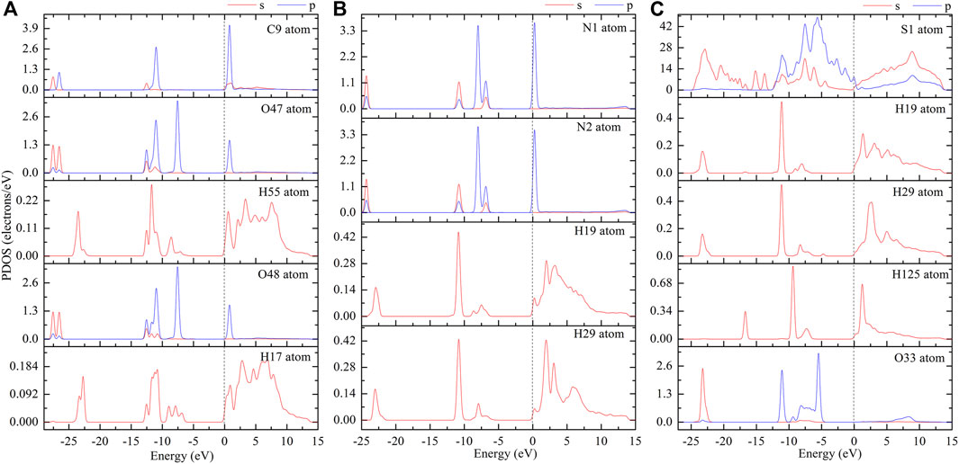
FIGURE 7. PDOS curves of absorbed CO2 (A), N2 (B), and H2S (C) on MH(001) surface (please refer to the atom names in Figure 6).
The H-bonding effect mainly comes from the dispersion interactions of the interfacial electrons. Based on the PDOS curves, one can note that there are resonant peaks between the interfacial atoms, especially between the H atoms of H2O and the O atoms of CO2 (or N atoms of N2, S, and H atoms of H2S).
The dispersion interactions are mainly contributed from the electrons with orbitals around the Fermi level. Therefore, the orbital images for the interfacial models of CO2, N2, and H2S molecules are depicted in the energy range from −1 eV to +1 eV (Figure 8).

FIGURE 8. Interfacial electronic orbitals of absorbed CO2 (A), N2 (B), and H2S (C) on MH(001) surface (energy level range: −1∼1 eV).
By combining the PDOS curves and the orbital images, it can be confirmed that, for the adsorptions of CO2, N2, and H2S molecules, the interfacial H-bonds forms between the interfacial atoms. For the absorbed CO2 molecule, the bonds will form mainly between O-2p in CO2 and H-1s in H2O. Similarly, for the absorbed N2 molecule, the bonds will form mainly between N-2p in N2 and H-1s in H2O. However, for the absorbed H2S molecule, the bonds will form not only between S-3p in H2S and H-1s in H2O but also between H-1s in H2S and O-2p in H2O.
4 Summary
In the present work, by utilizing MD and DFT computations, the adsorptions of CO2, N2, CO, H2S, CH4, and H2O onto methane hydrate surface are investigated. The methane hydrate planes of (001) and (110), and various cleaving sites are compared with cleavage energies. The sI-MH(001) is more likely to exist comparing with MH(110). Two (001) surfaces of MH(001)-I and MH(001)-II with different terminations (CH4+H2O and H2O only, respectively) are compared by examining the adsorption energies of these molecules. The molecules tend to adhere onto the surface MH(001)-I (termination CH4+H2O) with more negative adsorption energy. The priority order of these molecules’ adsorptions can be queued as: H2O > H2S > CO2 > N2 > CH4 > CO. So, CO2, N2, and H2S have potential to replace the CH4 in methane hydrate. The interfacial bonds and electronic interactions of these three molecules are narrowly investigated with PDOS and electron orbital. The interfacial H-bonds forms between the interfacial atoms for the adsorptions of CO2, N2, and H2S. For the absorbed CO2 molecule, the bonds will form mainly between O-2p in CO2 and H-1s in H2O. Similarly, for the absorbed N2 molecule, the bonds will form mainly between N-2p in N2 and H-1s in H2O. However, for the absorbed H2S molecule, the bonds will form not only between S-3p in H2S and H-1s in H2O but also between H-1s in H2S and O-2p in H2O.
Data availability statement
The raw data supporting the conclusion of this article will be made available by the authors, without undue reservation.
Author contributions
MZ: conceptualization, methodology, and software; BZ: data curation and writing—original draft; JhL: validation and investigation; TL: supervision; JnL: writing—review and editing.
Acknowledgments
The authors acknowledge the financial support from the Youth Innovation Team of Xi’an Shiyou University (Grant No. 2019QNKYCXTD04). Support from the Center for High Performance Computing of Northwestern Polytechnical University is also gratefully appreciated.
Conflict of interest
BZ was employed by the company No. 2 Gas Production Plant, PetroChina Changqing Oilfield Company.
The remaining authors declare that the research was conducted in the absence of any commercial or financial relationships that could be construed as a potential conflict of interest.
Publisher’s note
All claims expressed in this article are solely those of the authors and do not necessarily represent those of their affiliated organizations, or those of the publisher, the editors, and the reviewers. Any product that may be evaluated in this article, or claim that may be made by its manufacturer, is not guaranteed or endorsed by the publisher.
References
Cao, X., Huang, Y., Jiang, X., Su, Y., and Zhao, J. (2017). Phase diagram of water–methane by first-principles thermodynamics: Discovery of MH-IV and MH-V hydrates. Phys. Chem. Chem. Phys. 19, 15996–16002. doi:10.1039/c7cp01147d
Cha, M., Shin, K., Lee, H., Moudrakovski, I. L., Ripmeester, J. A., and Seo, Y. (2015). Kinetics of methane hydrate replacement with carbon dioxide and nitrogen gas mixture using in situ NMR spectroscopy. Environ. Sci. Technol. 49, 1964–1971. doi:10.1021/es504888n
Chong, Z. R., Yang, S. H. B., Babu, P., Linga, P., and Li, X. (2016). Review of natural gas hydrates as an energy resource: Prospects and challenges. Appl. Energy 162, 1633–1652. doi:10.1016/j.apenergy.2014.12.061
Clark, S. J., Segall, M. D., Pickard, C. J., Hasnip, P. J., Probert, M. I. J., Refson, K., et al. (2005). First principles methods using CASTEP. Z. fur Kristallogr. - Cryst. Mater. 220, 567–570. doi:10.1524/zkri.220.5.567.65075
Cox, S. J., Taylor, D. J. F., Youngs, T. G. A., Soper, A. K., Totton, T. S., Chapman, R. G., et al. (2018). Formation of methane hydrate in the presence of natural and synthetic nanoparticles. J. Am. Chem. Soc. 140, 3277–3284. doi:10.1021/jacs.7b12050
Cox, S. J., Towler, M. D., Alfè, D., and Michaelides, A. (2014). Benchmarking the performance of density functional theory and point charge force fields in their description of sI methane hydrate against diffusion Monte Carlo. J. Chem. Phys. 140, 174703. doi:10.1063/1.4871873
Hu, Y., Wang, S., and He, Y. (2021). Interaction of amino acid functional group with water molecule on methane hydrate growth. J. Nat. Gas Sci. Eng. 93, 104066. doi:10.1016/j.jngse.2021.104066
Hu, Y., Wang, S., Yang, X., and He, Y. (2021). Examination of amino acid inhibitor effect in methane hydrate dissociation via molecular dynamics simulation. J. Mol. Liq. 325, 115205. doi:10.1016/j.molliq.2020.115205
Huang, Y., Li, K., Jiang, X., Su, Y., Cao, X., and Zhao, J. (2018). Phase diagram of methane hydrates and discovery of MH-VI hydrate. J. Phys. Chem. A 122, 6007–6013. doi:10.1021/acs.jpca.8b02590
Jendi, Z. M., Servio, P., and Rey, A. D. (2015). Ideal strength of methane hydrate and ice Ih from first-principles. Cryst. Growth Des. 15, 5301–5309. doi:10.1021/acs.cgd.5b00829
Kirchner, M. T., Boese, R., Billups, W. E., and Norman, L. R. (2004). Gas hydrate single-crystal structure analyses. J. Am. Chem. Soc. 126, 9407–9412. doi:10.1021/ja049247c
Kvenvolden, K. A. (1988). Methane hydrate - a major reservoir of carbon in the shallow geosphere? Chem. Geol. 71, 41–51. doi:10.1016/0009-2541(88)90104-0
Liang, S., Rozmanov, D., and Kusalik, P. G. (2011). Crystal growth simulations of methane hydrates in the presence of silica surfaces. Phys. Chem. Chem. Phys. 13, 19856–19864. doi:10.1039/c1cp21810g
Liao, B., Wang, J., Han, X., Wang, R., Lv, K., Bai, Y., et al. (2022). Microscopic molecular insights into clathrate methane hydrates dissociation in a flowing system. Chem. Eng. J. 430, 133098. doi:10.1016/j.cej.2021.133098
Lunt, D. J., Ridgwell, A., Sluijs, A., Zachos, J., Hunter, S., and Haywood, A. (2011). A model for orbital pacing of methane hydrate destabilization during the Palaeogene. Nat. Geosci. 4, 775–778. doi:10.1038/ngeo1266
Martos-Villa, R., Francisco-Márquez, M., Mata, M. P., and Sainz-Díaz, C. I. (2013). Crystal structure, stability and spectroscopic properties of methane and CO2 hydrates. J. Mol. Graph. Model. 44, 253–265. doi:10.1016/j.jmgm.2013.06.006
Matsui, H., Jia, J., Tsuji, T., Liang, Y., and Masuda, Y. (2020). Microsecond simulation study on the replacement of methane in methane hydrate by carbon dioxide, nitrogen, and carbon dioxide–nitrogen mixtures. Fuel 263, 116640. doi:10.1016/j.fuel.2019.116640
McQuaid, M. J., Sun, H., and Rigby, D. (2004). Development and validation of COMPASS force field parameters for molecules with aliphatic azide chains. J. Comput. Chem. 25, 61–71. doi:10.1002/jcc.10316
Okwananke, A., Yang, J., Tohidi, B., Chuvilin, E., Istomin, V., Bukhanov, B., et al. (2018). Enhanced depressurisation for methane recovery from gas hydrate reservoirs by injection of compressed air and nitrogen. J. Chem. Thermodyn. 117, 138–146. doi:10.1016/j.jct.2017.09.028
Phrampus, B. J., and Hornbach, M. J. (2012). Recent changes to the Gulf Stream causing widespread gas hydrate destabilization. Nature 490, 527–530. doi:10.1038/nature11528
Shu, J., Chen, X., Chou, I. M., Yang, W., Hu, J., Hemley, R. J., et al. (2011). Structural stability of methane hydrate at high pressures. Geosci. Front. 2, 93–100. doi:10.1016/j.gsf.2010.12.001
Sloan, E. D. (2003). Fundamental principles and applications of natural gas hydrates. Nature 426, 353–359. doi:10.1038/nature02135
Sun, H. (1998). Compass: An ab initio force-field optimized for condensed-phase ApplicationsOverview with details on alkane and benzene compounds. J. Phys. Chem. B 102, 7338–7364. doi:10.1021/jp980939v
Thierfelder, C., Hermann, A., Schwerdtfeger, P., and Schmidt, W. G. (2006). Strongly bonded water monomers on the ice Ih basal plane: Density-functional calculations. Phys. Rev. B 74, 045422. doi:10.1103/physrevb.74.045422
Tkatchenko, A., and Scheffler, M. (2009). Accurate molecular van der Waals interactions from ground-state electron density and free-atom reference data. Phys. Rev. Lett. 102, 073005. doi:10.1103/physrevlett.102.073005
Walsh, M. R., Koh, C. A., Sloan, E. D., Sum, A. K., and Wu, D. T. (2009). Microsecond simulations of spontaneous methane hydrate nucleation and growth. Science 326, 1095–1098. doi:10.1126/science.1174010
Wang, H., Zhu, X., Cao, J., Qin, X., Yang, Y., Niu, T., et al. (2020). Density functional theory studies of hydrogen bonding vibrations in sI gas hydrates. New J. Phys. 22, 093066. doi:10.1088/1367-2630/abb54c
Zhang, L., Kuang, Y., Zhang, X., Song, Y., Liu, Y., and Zhao, J. (2017). Analyzing the process of gas production from methane hydrate via nitrogen injection. Ind. Eng. Chem. Res. 56, 7585–7592. doi:10.1021/acs.iecr.7b01011
Zhang, L., Yang, L., Wang, J., Zhao, J., Dong, H., Yang, M., et al. (2017). Enhanced CH4 recovery and CO2 storage via thermal stimulation in the CH4/CO2 replacement of methane hydrate. Chem. Eng. J. 308, 40–49. doi:10.1016/j.cej.2016.09.047
Keywords: methane hydrate (MH), adsorption priority, interfacial bonding, hydrogen bonds, DFT calculations
Citation: Zhang M, Zhao B, Li J, Li T and Li J (2022) Comparison of CO2, N2, CO, H2S, CH4, and H2O adsorptions onto sI methane hydrate surface. Front. Earth Sci. 10:965743. doi: 10.3389/feart.2022.965743
Received: 10 June 2022; Accepted: 26 August 2022;
Published: 20 September 2022.
Edited by:
Jianlin Zhao, ETH Zürich, SwitzerlandReviewed by:
Gang Liu, Taizhou University, ChinaAndreas Hermann, University of Edinburgh, United Kingdom
Copyright © 2022 Zhang, Zhao, Li, Li and Li. This is an open-access article distributed under the terms of the Creative Commons Attribution License (CC BY). The use, distribution or reproduction in other forums is permitted, provided the original author(s) and the copyright owner(s) are credited and that the original publication in this journal is cited, in accordance with accepted academic practice. No use, distribution or reproduction is permitted which does not comply with these terms.
*Correspondence: Ming Zhang, em05NzkyQHhzeXUuZWR1LmNu