 Charlotte Allen1
 Jeff Peakall
 David M. Hodgson
 Adam D. Booth
- 1School of Earth and Environment, University of Leeds, Leeds, United Kingdom
- 2TGS, Woking, United Kingdom
Models of the sedimentary architecture of submarine channel-levee systems and their formative flow processes are predominantly based on studies from low latitude settings. Here, we integrate high-resolution seismic reflection, bathymetry and GLORIA side scan data to document the architecture and interpret the formative processes of a series of ultra-high latitude (72–76°N) submarine channel-levee systems that feed lobe complexes off the Greenland margin. We demonstrate that the sedimentary architecture of the channel-fills are dominated by vertical or near-vertical sediment accumulation, reflecting the lack of, or very limited nature of, lateral migration over time. All the Greenland channel-levee systems show significant cross-sectional asymmetry, and a peak sinuosity of 1.38, on a low gradient slope (∼0.3°). The bounding external levees are very thick (∼200 m) and wide relative to low latitude systems. Comparison of these channel-levee systems with other examples reveals that these characteristics appear to be common to systems in high and ultra-high latitudes, suggesting latitudinal controls in the sedimentary architecture of submarine channel-levee systems. The differences between high- and low-latitude systems is likely due to the interplay of physical forcing (i.e., Coriolis force) and climatic factors that control sediment calibre and flow type, both of which are latitudinally dependent. Several formative mechanisms for supressing the initial phase of lateral migration and subsequent asymmetrical development are proposed, including:i) rapid channel aggradation, (ii) Coriolis forcing causing preferred deposition on the right-hand side of the channel, and iii) variance in flow properties, with traction- and suspension-dominated flows deposited on opposing sides of the channel. We argue that a high latitudinal location of larger channel-levee systems may result in the dominance of vertical stacking of channels, the construction of large external levees, and the development of a low sinuosity planform.
1 Introduction
Submarine channels form the main conduit for sediment transport from terrestrial to deep-water settings via a range of sediment-gravity currents. Many studies have examined the evolution (e.g. Peakall et al., 2000; Romans et al., 2011; Sylvester et al., 2011; Janocko et al., 2013; Hansen et al., 2017), flow processes (e.g., Peakall et al., 2000; Corney et al., 2006; Kolla et al., 2007; Mohrig and Buttles, 2007; Ezz et al., 2013; Ezz and Imran, 2014; Dorrell et al., 2018; Palm et al., 2021), and sedimentary architecture (e.g., Pirmez and Flood, 1995; Posamentier and Kolla, 2003; Mayall et al., 2006; Deptuck et al., 2007; Wynn et al., 2007; Gamberi et al., 2013; Jobe et al., 2016) of low- and mid-latitude submarine channels. These observations have led to the development of a number of models for sinuous submarine channel-levee systems (e.g., Peakall et al., 2000; Stow and Mayall, 2000; Deptuck et al., 2007; McHargue et al., 2011).
While submarine channel sinuosity has previously been thought to be analogous in many respects to fluvial systems (e.g., Flood and Damuth, 1987; Clark et al., 1992), it has been argued that there is latitudinal variation in the peak sinuosity of channels, with low sinuosity at high-latitudes and vice-versa (Peakall et al., 2012; Peakall et al., 2013). Incorporation of end-member examples with sinuosity measured over a single bend wavelength, to examples dominantly measured over reach scales, has been used to argue against this relationship (Sylvester and Pirmez, 2019). However, irrespective of these arguments, there is a near absence of higher sinuosity systems north or south of ∼50° (Peakall et al., 2012, 2013) and no examples beyond ∼55°. It has been postulated, that in many cases, high latitude channel system evolution, morphology, and sedimentation vary significantly from low latitude systems, through a combination of physical forcing, and climatic-driven processes such as flow type and sediment calibre (Peakall et al., 2012; Cossu and Wells, 2013; Cossu et al., 2015; Davarpanah Jazi et al., 2020).
The influence of the Coriolis force on submarine channels, has in particular, been examined. Preferential deposition along one side of the channel, both inside and outside the channel, is predicted in systems where Coriolis forcing is dominant over the centrifugal force (Cossu and Wells, 2013; Wells and Cossu, 2013; Cossu et al., 2015; Davarpanah Jazi et al., 2020). The effect of a dominant Coriolis force results in the deflection of flows, and therefore overbank deposition to the right of the flow direction in the Northern Hemisphere (and left in the Southern Hemisphere). Physical experiments have also shown the importance of Coriolis forcing on different flow types, with traction and suspension-dominated intra-channel flows exhibiting opposing deposition/erosion patterns (Cossu et al., 2015; Davarpanah Jazi et al., 2020). Traction dominated intra-channel sedimentation is to the left hand side (as looking downstream) in submarine channels in the northern hemisphere. In contrast, suspension dominated sedimentation follows the density field, which may be on the right hand side, or alternate between bends, depending on whether the velocity and density fields are coupled or uncoupled (Cossu et al., 2015; Davarpanah Jazi et al., 2020). These hypotheses have only been validated against contourite channels (sensu Akhmetzhanov et al., 2007; Stow et al., 2013) at ocean gateways (Cossu et al., 2015), and examples of deep-ocean channels (sensu Peakall and Sumner, 2015), specifically the North Atlantic Mid-Ocean Channel (NAMOC) and the North Pole NP-28 Channel, which are not associated with prominent fan deposits (Cossu et al., 2015; Boggild and Mosher, 2021).
The presence of tributary channel systems, which are likely more common in high-latitude systems where glacial inputs are line sourced (zone of input points across an area) rather than point sourced (single input point), has also been suggested as an important control on channel morphology, albeit these can also be found in some low latitude examples (Bourget et al., 2008; Sylvester and Pirmez, 2019). Sylvester and Pirmez (2019) also argue that the type of channel influences its sinuosity, and that broad deep-ocean channels favour low sinuosity, in contrast to river-dominated submarine fan channels.
These hypotheses are hard to test, as detailed studies of high latitude submarine channel systems remain limited, and have been dominated by broad deep-ocean channels (e.g., Klaucke et al., 1997; Boggild and Mosher, 2021). Therefore there is a need to assess additional high-latitude submarine channels, and in particular high latitude channel-levee systems associated with down-dip fan deposits. Here we use reprocessed seismic reflection data from the Greenland Basin to study multiple high latitude submarine channel-levee systems and their evolution for the first time. Previous authors have noted the existence of these channel systems whilst examining broader scale basinal features and implications for glacial processes (Mienert et al., 1993; Ó Cofaigh et al., 2002; Wilken and Mienert, 2006; Berger and Jokat, 2008). Other authors have examined the influence of glacial cyclicity upon the channel planform morphology and associated seafloor landforms in the surrounding basin (Ó Cofaigh et al., 2004; García et al., 2012; García et al., 2016), but no studies have examined their stratigraphic evolution and architecture, nor proposed a process-based mechanism for their formation.
By using a multi-dataset approach, the planform morphology and architectural observations from a set of glacially-influenced, high latitude (72–76°N) channel-levee systems are documented. This work addresses the following objectives: 1) to describe the architectural variations between high- and low-latitude channel-levee systems; 2) to examine the large-scale variation in channel evolution between high- and low-latitude systems; and 3) to discuss the underlying process-controls on high-latitude submarine channel–levee systems. These different aspects are combined into a new model for high latitude channel-levee system evolution and sedimentary architecture.
2 Geological setting
2.1 NE Greenland
The study area is located within the Greenland Basin, offshore NE Greenland, between the latitudes of ∼72–76°N (Figure 1). The basin is bounded by the Greenland Fracture Zone to the north, the Jan Mayen Fracture Zone to the south, and the Mid-Atlantic Ridge to the east (Figure 1). The basin has undergone compression, extension, uplift, subsidence and magmatism since initial break-up of the Norwegian-Greenland conjugate margins in the early Eocene (Lundin and Dore, 2002; Voss and Jokat, 2009), but salt is not observed in contrast to the Danmarkshavn Basin to the north (Rowan and Jarvie, 2020). The Kejser Franz Josef margin (KFJ) forms a 180 km-wide shelf in the southwest of the study area, with a 3° continental slope from the shelf break at ∼−350 m to depths of up to −2,300 m. The shelf widens northwards to 220 km at the Norske Margin (NM).
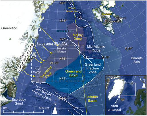
FIGURE 1. Regional map of the Greenland Basin, with the study area outlined (also shown in Figure 2A). Location map showing Greenland and NW Europe in bottom right corner, for regional context. Bathymetric trough locations taken from Wilken and Mienert (2006) KFJ = Kejser Franz Josef margin. Background image from Google Earth. The Norske Margin and KFJ Margin terms follow those of García et al. (2012) where these are defined as the areas off of the Norske Trough and Kejser Franz Josef Fjord respectively. Thus these terms refer to the northern and southern ends of the study area, and are local to these areas; therefore the geographic boundary between these two areas is undefined (García et al., 2012).
2.2 Glacial history and palaeoceanography
Detritus carried by the Greenland Ice Sheet provided the main source of sediment, with increased outer shelf and continental slope deposition coincident with intensification of glacial activity during the Plio-Pleistocene (García et al., 2012). Glacial sediments were deposited on the outer shelf and continental slope during the Early and Late Pliocene (Vanneste et al., 1995; Solheim et al., 1998), with a further phase of deposition linked to the final advance of the Greenland Ice Sheet in the Saalian (Håkansson et al., 2009). The maximum extent of the ice sheet is still under discussion. Some authors argue for a maximum ice extent similar to the present day (Andrews et al., 1996; Funder and Hansen, 1996; Hjort, 1997), with glaciation limited to the inner continental shelf. However, more recent work has provided direct evidence, in the form of 10Be-dated erratic boulders and terminal moraines from the Scoresby Sund area, for ice sheet advance across the shelf, delivering debris and sediment-laden meltwaters directly to the continental slope (Evans et al., 2002, 2009; Håkansson et al., 2007; Dowdeswell et al., 2010). Average sedimentation rates during the Plio-Pleistocene are estimated to vary from 0.048 m kyr−1 (Berger and Jokat, 2008) to 0.16 m kyr−1 (Ó Cofaigh et al., 2004), reaching a peak of 0.79 m kyr−1 during glacial maxima (Ó Cofaigh et al., 2004). From the start of deglaciation of the margin 17–18 ka (Evans et al., 2002) to ∼13 ka there was a transition from dominantly glacially-influenced debris flow and turbidity current deposition to hemipelagic sedimentation (Ó Cofaigh et al., 2002; Ó Cofaigh et al., 2004; Wilken and Mienert, 2006). The decrease in turbidity current and debris flow frequency during deglaciation suggests rapid sediment delivery during full glacial, and retreating glacial conditions (Evans et al., 2009; Winkelmann et al., 2010). Due to the nature of glacial sedimentation, the basin likely underwent several cycles of waxing and waning sediment supply (Vorren et al., 1998).
The modern ocean current regime is characterised by two strong, southward flowing thermohaline currents. The East Greenland Current transports polar water at depths of up to ∼−200 m and the Return Atlantic Current ranges from −150 to −800 m depth, transported along the shelf and slope (Wilken and Mienert, 2006). Previous studies have inferred that surface ocean currents in the eastern North Atlantic during Plio-Pleistocene glaciations were broadly similar to the present day (Newton et al., 2018). Further to this, basins to the north of the Greenland Fracture Zone (Figure 1) report the presence of contourite deposits related to the opening of the Fram Strait in the Miocene (Døssing et al., 2016). However, drift sheets and other features of contourite deposition are unreported in the study area, although several contourite drifts are reported at the same latitude of the study area on the Norwegian side (e.g., Rebesco et al., 2013; Rydningen et al., 2020). Furthermore, previous studies have identified morphological characteristics of overbank deposition as indicative of turbidity current overspill, as opposed to contour current deposition (García et al., 2012).
2.3 Study area
The study area covers parts of the continental shelf and the continental slope from the shelf break to the deep basin (350–3,700 m below mean sea-level). Numerous volcanic edifices are present on the basin-floor that influence sediment dispersal patterns, including the Vesteris Seamount in the east of the study area (Figure 2). Two different sedimentary regimes were present in the Greenland Basin: 1) the northern Norske Margin, dominated by sediment remobilisation on the continental slope and stacked debris flow lobes on the continental rise, and 2) the southern KFJ margin, characterised by well-developed channel-levee systems and lobes (Figure 3). The northern Norske margin sedimentation has been affected by some regional seismicity, in contrast to the south (García et al., 2012). In the southern KFJ margin, four SW-NE trending channel-levee systems are present and extend for ∼400 km, following the regional slope gradient (Ó Cofaigh et al., 2004). Two of these transition north-eastwards into submarine lobe complexes (herein named C1 and C3), and two others become morphologically indistinct to the NE (herein named C2 and C4) (Ó Cofaigh et al., 2004; García et al., 2012) (Figure 2). The channel-levee systems are adjacent to three shelf-crossing bathymetric troughs, themselves adjoining the mouths of major fjords to the west (Dowdeswell et al., 1998; Vorren et al., 1998; Ó Cofaigh et al., 2004; Wilken and Mienert, 2006; García et al., 2012). Two further shelf troughs in the north of the basin (Figure 1), likely also provide major sediment fairways (Ó Cofaigh et al., 2004). The southernmost system (C1; traced furthest up-dip) is characterised by numerous branching tributaries in its upstream section. This tributive network was interpreted by Ó Cofaigh et al. (2006) to result from hyperpycnal-dominated input, with downslope convergence into a larger trunk channel (Figure 2). The C2-C4 channels all initiate in close proximity to one another, and are likely sourced from the same bathymetric troughs, providing a similar sediment supply regime (Figure 2).
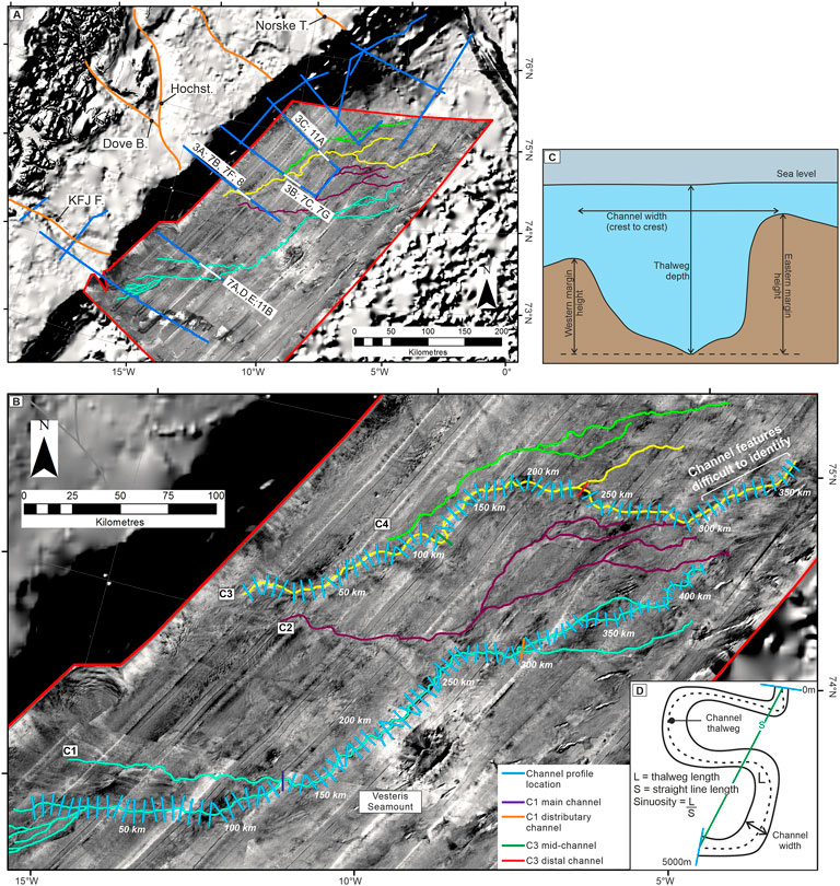
FIGURE 2. (A) IBCAO bathymetric dataset, and GLORIA dataset (outlined in red) used in morphometric analysis. 2D seismic survey delineated in blue, with corresponding figure numbers. Channel systems studied shown in cyan, magenta, yellow and green. Orange lines mark the trend of former glacial troughs in García et al. (2012); Norske T.: Norske Trough; Hochst: Hochstetterbugten; Dove B: Dove Bugt; KFJ F.: Kejser Franz Josef Fjord. (B) Location of profiles used to parameterise channel shown in cyan, with the transition from C1 feeder channel to C1 main channel delineated in purple, and C1 main channel to distributary channel delineated in orange. C3 proximal to mid-channel delineated in green, and mid-channel to distal channel delineated in red. (C) Parameter calculations for cross-sectional channel analysis. (D) Parameters for planform channel analysis.
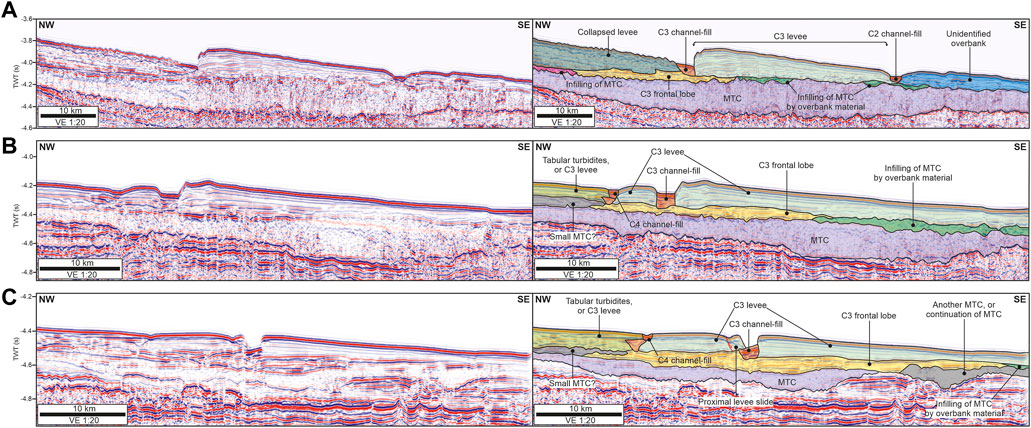
FIGURE 3. 2D seismic sections (3A updip, through to 3C downdip) showing temporal evolution and cross-cutting relationships of C2-C4, beginning with mass-transport complex emplacement, followed by frontal lobe deposition. (A) Shows propagation and deposition of C3, with C2 cutting into the right-hand levee of C3. (B) Cross-section taken ∼60 km further down dip, showing a thicker package of frontal lobe deposits, overlain by C3, the left levee of which is cut by C4. (C) (∼75 km down-dip) shows further thickness increases of frontal lobe deposits, as well as C4 again cutting into the left levee of C3. The frontal lobe deposits are linked to channel C3 because only C3 is present in section A, it underlies the C3 channel and levees in sections B and C, and because C2 and C4 are shown to be younger than C3. Channel cross-section locations are shown in Figure 2A.
3 Methodology
3.1 IBCAO and GLORIA
Morphological observations and mapping were conducted using bathymetric data, and a long-range, side scan GLORIA dataset, the latter covering an area of 115,000 km2 (Figure 2A). Receivers for the GLORIA data were towed at a spacing of 400 m, at 50 m depth, operating at 6.5 kHz, with a swath width of 50 km. The GLORIA data were compiled into a mosaic with a scale of 1:375,000 and a resolution of 50 m × 50 m per pixel on a polar stereographic projection (Mienert et al., 1993; Wilken and Mienert, 2006). Morphometric analysis of bathymetry utilised the International Bathymetric Chart of the Arctic Ocean (IBCAO) version 4.0 which was compiled using a base grid resolution of 2 km × 2 km, merged with higher resolution grids of 0.2 km × 0.2 km and 0.1 km × 0.1 km grids on an IBCAO polar stereographic projection (Jakobsson et al., 2020. These higher resolution datasets are in this area dominantly sourced from multibeam data, along with gridded compilations (Jakobsson et al., 2020 their Figure 4).
Sonar and bathymetric datasets were imported into ESRI ArcGIS© to create a regional base map with an area of ∼330,000 km2 (Figure 2A). IBCAO and GLORIA data were analysed in ESRI ArcGIS© to pick channel paths and undertake mapping of other geomorphic features. Geometric channel profiles were extracted perpendicular to local channel orientation, at intervals of ∼5 km, from west to east facing downstream (location shown by cyan lines in Figure 2B) and were used to collect morphometric data. From these sections, channel width and channel margin/levee height above channel floor were determined (Figure 2C), permitting quantitative and qualitative analysis of channel morphology. Channel width was calculated between levee crests. Channel margin/levee height was calculated by projecting crest height over the thalweg and measuring the difference, and is used in place of channel depth due to significant asymmetry in overbank height (Figure 2C). Channel margin is used instead of levee along some of the channel, for sedimentary deposits where no specific overbank geometry is visible, with levee reserved for wedge-shaped geomorphic features. These datasets were combined into scatter plots to allow study of the downstream variation in channel width, channel margin height and sinuosity along each channel. Geomorphic features were classified as depositional elements based on planform and cross-sectional geometry, relationships to other features in the basin, and were combined with seismic datasets where available to validate element interpretation. Channel planform was delineated using bathymetric and GLORIA data, with shape-files of channel planform imported into Petrel to provide context for subsurface datasets. Channel sinuosity was determined using the Hansen et al. (2017) methodology, with average sinuosity calculated over 5 km using a sliding window, with a 1 km overlap between each window, by dividing channel thalweg length (L) by average channel course (S) to determine reach sinuosity (Figure 2D).
Individual morphological measurements will have error bars attached which in an absolute sense for any given cross-section width estimate may be substantial (e.g., absolute maximum error bar for the 0.1 × 0.1 km grid is 70.7 m; see Palm et al., 2021). However, the errors of interest are not absolute values as there will be both positive and negative errors on the two end points of each section. Furthermore, combined measurement for say average channel width are much reduced as with increasing numbers of measurement points errors tend towards zero (see Palm et al., 2021 for a detailed discussion of errors in bathymetric data). Given the combined bathymetric dataset is based on different data types that comprise multiple resolutions, actual errors are not calculated herein (see Jakobsson et al., 2020 for discussion), but measurements of >65 cross-sections for each of the two analysed channels, and channel widths of ∼1–7 km suggests that measurement error as a function of channel width is comparatively small.
3.2 Seismic reflection survey
One thousand nine hundred and 50 km of multi-channel, time-migrated, 2D seismic reflection surveys (line location represented by blue lines in Figure 2A) were used to study subsurface architecture, and system evolution through time. Data were collected in 2003 with 3 km long streamers and a source array comprising 5 × 9 L airguns. No frequencies higher than 100 Hz were anticipated. Data binning used a spacing of 25 m, and the nominal vertical resolution is 10 m (i.e., ¼ of the wavelength of a 50 Hz wavelet, travelling at 2000 m s−1). The dataset was reprocessed in 2010 and is presented in European standard polarity, with the positive reflection coefficient and impedance contrast at the seafloor reflector represented by a red trough; data are assumed to be zero phase. Quantitative architectural measurements were calculated after depth conversion of the seismic grid using the velocity model outlined in Berger and Jokat (2008), and assuming constant internal velocities. Due to data degradation after depth conversion, architectural mapping was undertaken in two-way time (TWT). Conventional 2D mapping techniques were used to interpret the evolution and architecture of the channel-levee systems and additional depositional landforms (Table 1).
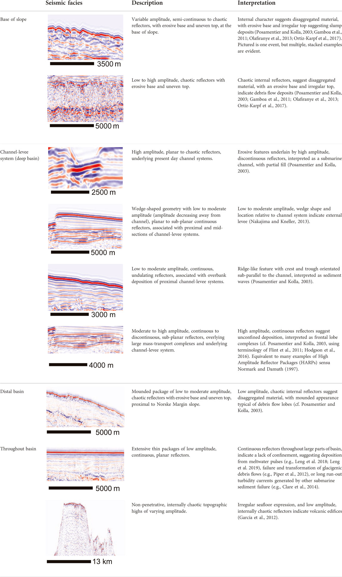
TABLE 1. Seismic facies found within the Greenland Basin; seismic data are in SEG negative standard polarity.
4 Results
4.1 Channel geomorphology
Seismic facies have been determined (Table 1) and in conjunction with bathymetric, GLORIA and 2D seismic reflection datasets, are used to interpret channel geomorphology and stratigraphic relationships. Four major channel-levee systems (named C1 to C4 from south to north) have been identified in all three datasets, spatially related to large cross-shelf bathymetric troughs on the KFJ margin that terminate at the heads of the channel-levee systems (Figure 1). Channel systems overlie tabular packages that thicken down-dip (Figure 3), interpreted as frontal lobes formed where flow expands from a channel mouth (sensu Flint et al., 2011; Hodgson et al., 2016), which overlie large (∼250 m thick) mass transport complexes (MTC’s). C1 and C3 exhibit the greatest degree of down-cutting into underlying deposits, the largest levees, and the most prominent surface expression, and consequently we primarily focus on these two systems. No age relationships between C1 and C3, C1 and C2, or C2 and C4 can be drawn from the data. However, C2 incises into the right levee of C3, and C4 incises into the left levee of C3 (Figure 3), indicating that C2 and C4 are younger than C3.
4.1.1 Channel-levee system C1
The southernmost channel-levee system, named C1 in this study, has been studied by previous authors (e.g., Mienert et al., 1993; Dowdeswell et al., 2002; Ó Cofaigh et al., 2004; Wilken and Mienert, 2006; García et al., 2012). Based on planform and cross-sectional observations, the C1 system has been divided into three segments: proximal feeder channels, a main channel-levee system, and distal distributary channels, with changes in cross-sectional profile corresponding to changes in planform geometry (Figures 3, 4). These subdivisions are based on planform morphology, as well as width, depth, and the development or degradation of external levees. Subdivisions are delineated in planform by navy blue and orange lines on Figure 2B.
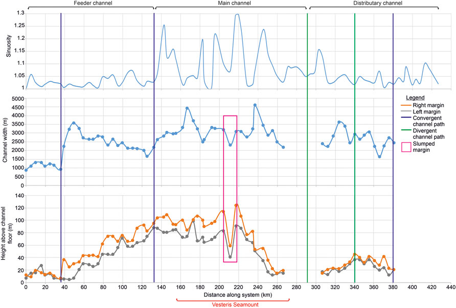
FIGURE 4. Comparison of sinuosity, channel width, channel margin height (‘right and left margin’ in legend), thalweg depth and profile symmetry for C1. Convergence and divergence of the channel path are represented by purple and green lines, respectively. Missing gaps in channel height and width measurements are through degradation of the channel form in the data, likely related to vertical resolution, although planform expression is still present. Right and left channel margin with respect to flow direction. ‘Slumped margin’ refers to slumping of the channel margin.
Sinuosity, channel width and channel margin height above channel floor for C1 are compared in Figure 4. Peak sinuosity is 1.34 (rounded to 1.3) - observed in the mid-section of the channel close to the Vesteris Seamount (Figure 4). Right-hand channel margin height is consistently higher than left-hand, except for ∼10 km between 30 km and 40 km along system, with fluctuations down dip, and is highest in the middle of the system (Figure 4). As with channel margin height, channel width varies and is greatest (up to ∼3,500 m) in the main trunk channel (middle) section of the system, before decreasing down dip. Deterioration in data quality (likely related to vertical resolution) means channel path is lost in bathymetric cross-sections between 275 and 310 km down-system, but remains visible in planform in the side scan sonar imagery, where channels can be seen to diverge (Figure 4).
4.1.2 Channel-levee system C3
C3 initiates ∼110 km northeast of C1 and is visible from a water depth of ∼2,800 m (Figure 2). Channel width and depth at this point (Figure 5) suggests that the system originated higher on the slope, but has been buried by a mass flow event. Sinuosity, channel width and channel margin height above channel floor for C3 are compared in Figure 5. Overall, system length is ∼300 km, with a peak sinuosity of 1.12 in the middle of the system (Figure 5). Three distinct channel morphologies are observed, termed the proximal, mid, and distal distributary channel (Figure 5), based on planform morphology and cross-sectional appearance. Overall, channel margin height decreases down-dip (exhibiting small fluctuations), with width increasing until the transition between the proximal and mid-channel sections, before decreasing distally and diverging a number of times (Figure 5). System width is initially ∼3 km, although this is likely related to slumping of the external levee on the left margin of the channel (Figure 5). The height of the right-hand channel margin is consistently higher than the left-hand (Figure 5).
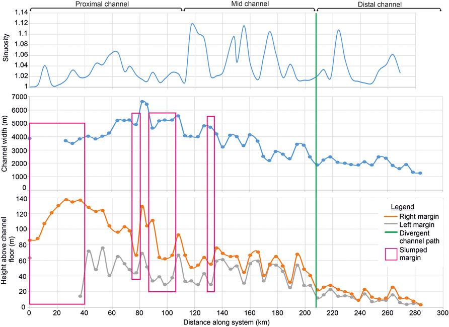
FIGURE 5. Comparison of sinuosity, channel width, channel margin height (‘right and left margin’ in legend), gradient, thalweg depth and profile symmetry for C3. The divergence of the channel path is represented by a green line. Right and left channel margin with respect to flow direction. ‘Slumped margin’ refers to slumping of the channel margin.
4.2 Intrachannel features and stacking patterns
A number of intrachannel features are visible in planform and cross-sectional profiles within C1 (Figure 6). In more sinuous reaches of the channel, intrachannel features are located on the inner bend (Figures 6A–J), and are characterised in cross-section by stepped (Figures 6C,D,G), planar (Figures 6I,J) or hybrid (Figure 6H) geometries. In planview, high-angle, arcuate features correspond with a stepped geometric profile (Figures 6C,D,G), and these features are interpreted as inner external levee failure, resulting in deposition of an intrachannel mass-transport deposit (MTD). Planar surfaces are restricted to the highest sinuosity sections of the channel, and represent either point bar deposits (e.g., Peakall et al., 2000), or terrace surfaces (sensu Hansen et al., 2015), that possibly formed sites for subsequent deposition. In straighter and lower sinuosity reaches of a channel, geometric profiles are also characterised by stepped surfaces that correspond in planview with large areas of inner external levee failure and MTD emplacement. Broader tectonically-driven structures are not observed within the seismic profiles.
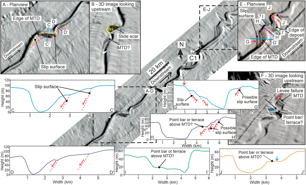
FIGURE 6. (A) Planview of terrace surfaces in a low sinuosity section of channel C1, with (B) showing a possible slide scar. (C,D) Cross-sectional profiles of terrace surfaces, with slip surfaces interpreted based on geomorphic signature. (E,F) Planview and 3D view of terrace surfaces. (G) Cross-sectional profile showing a stepped geometry with slip surfaces interpreted. (H) Cross-sectional profile showing stepped and planar geometries, interpreted as a possible slip surface and point bar deposit. (I,J) are interpreted as inner external levee failure and point bar deposits, respectively.
Multiple examples of vertical stacking of channel-fills are observed in all systems, with limited lateral stacking (Figure 7). Vertical stacking is present in the proximal/feeder channels of C1 (90 m of vertical aggradation; Figures 7A,E) and C3 (70 m; Figures 7B,F), and the mid-sections of C3 (80 m; Figures 7C,G), with a slight (10s of metres) lateral component as a function of width increase with vertical aggradation. The right-hand surface in Figure 7D has become a surface for subsequent deposition.
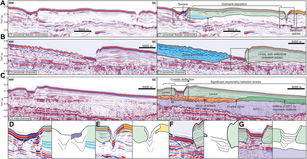
FIGURE 7. (A,B) Interpreted seismic cross-sections (locations shown in Figure 2A) from different channel locations, with vertical channel stacking outlined, and shown in (D–G). Significant levee asymmetry is also evident in (C), with the levee reaching ∼40 km in width.
4.3 External levees
Deposition on the KFJ Margin is characterised by external levees (Table 2) and unconfined overbank turbidity current deposition (Table 1). Interpretation of seismic facies (Table 1) was used to quantify the external levees (Figure 8), which are larger on the right-hand side of channel-levee systems, decreasing in size and amplitude down dip (Figure 3). The largest external levees are associated with the C3 channel (Figure 3). Numerous sediment wave fields are interpreted in up-dip areas, predominantly on the right-hand side of the system, associated with these external levees (Figures 3A, 8).

TABLE 2. Dimensions of right-hand external levees in the Greenland Basin.
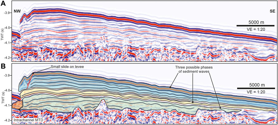
FIGURE 8. Seismic reflection cross-section showing extensive, asymmetric sediment waves on the eastern levee of C3 (C3(A) in Table 2), with (B) and without (A) interpretation. For figure location, see Figure 2A.
Internal properties of external levees vary along system, with the largest, most proximal C3(A) (Figures 3A, 7B, 8) characterised by well-developed, up-slope migrating, asymmetric sediment waves throughout the levee stratigraphy (Figure 3A). These sediment waves have heights of up to 25 m and wavelengths ranging from 4.5 km to 0.75 km, from channel proximal to channel distal parts of the external levee. A system age (i.e. age of channel initiation) of ∼2.5 Ma for C3 is based on radiocarbon dating of cores (to determine the cessation of glacially-influenced deposition), in conjunction with seismic stratigraphy in Wilken and Mienert (2006) and Berger and Jokat (2008), tied to ODP site 913. Average sedimentation rate for this external levee is calculated at 0.66 m kyr−1, an order of magnitude higher than the basin average of 0.048 m kyr−1, over the same time period (Berger and Jokat, 2008). Levee C3(B) (Figure 3B) shows possible smaller scale sediment wave development proximal to the channel margin, but predominantly exhibits planar, dipping reflectors, as does Levee C3(C) (Figure 3C).
4.4 Flow velocity estimates and Coriolis forcing
4.4.1 Overview
In order to assess the nature of flows in these channels, flow velocities are calculated, and these are utilised to examine the potential role of the Coriolis force. The relative strength of the Coriolis force to the centrifugal force is given by the Rossby number, which can be defined in two ways, based on either the radius of curvature, R, measured herein using the method of Brice (1974) Eq. (1), or channel width, W Eq. (2). Note that channel width is adopted when channels become sufficiently straight, as accurately measuring radius of curvature becomes problematic. Other parameters used in these calculations are the depth-averaged downstream velocity (Ū) and the Coriolis parameter, defined as
A key component of Rossby calculations is depth-averaged mean flow velocity, a difficult value to determine in subaqueous channel systems (Talling et al., 2013). Flow velocity is estimated with the following approaches; 1) utilising the super-elevation of a flow at a bend apex, as measured by differences in external levee heights Eq. (4), 2) using the same super-elevation approach but taken along a straight channel section Eq. (6), and, 3) by estimating the settling velocity of the coarsest grains transported Eq. (7). The results from each methodology are shown in Figures 9A,C, and compared with flow velocity estimates from García et al. (2012), using a fourth methodology based on using height and wavelength of sediment waves Eq. (8) following Normark et al. (1980) and Piper and Savoye (1993).
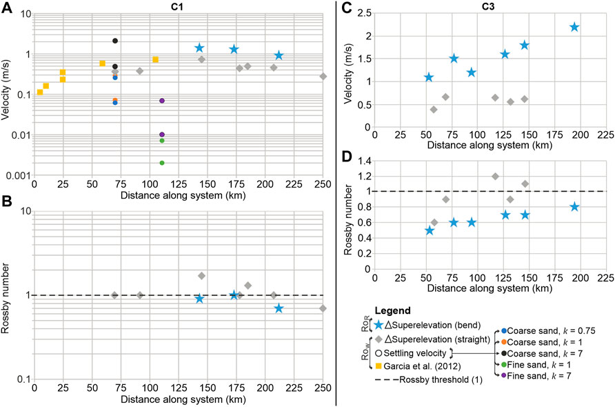
FIGURE 9. Comparison of estimated velocity values for C1 (A) and Rossby numbers calculated from these values (B) using the methodologies outlined in the main text. Velocity values are also estimated for C3 (C), and Rossby numbers for this system (D). Only two methodologies are used for C3, as grain size data for settling velocity estimates are unavailable, and García et al. (2012) only generated estimates for C1. Calculations using the superelevation of the flow, based on levee height differences at bend apexes or straight sections, are depth-averaged approaches, with settling velocity a localised approach. Settling velocity values have been estimated using a range of values for k (see Eq. (7) and associated text). For Rossby calculations, radius of curvature is used for the approach using bends, with channel width measurements used as the length scale where levee heights are used in straight sections. Note that A and B are on log scales whilst C and D use a linear scale, reflecting the range of the variables.
4.4.2 Flow estimation based on cross-channel super-elevation
Turbidity currents in bends are known to undergo super-elevation (the tendency for the flow to be higher on one bank than the other, due to the upper surface of the flow being tilted in the lateral direction) as a result of the centrifugal and Coriolis forces. Komar (1969) related the combined effects of the centrifugal and Coriolis forces to the opposing horizontal pressure gradient force that balances these two forces, for a flow at a bend apex, giving:
Where
Where H is the average height of flow. This formulation enables use of the known relationship between Froude number and slope based on experiments (see Bowen et al., 1984; Klaucke et al., 1997) – calculated herein for each channel section, using:
where
For a straight channel section, the centrifugal term 1/R can be neglected, giving:
Depth-averaged velocities range from 0.9 to 1.8 m s−1 for Eq. (4) (bend apices), and 0.36–0.73 for Eq. (6) (straight sections), using this force balance approach (Figure 9). It is noted that the range of values from both equations do not overlap. This variation between the two approaches perhaps reflects the limitations of trying to balance forces at a given point around a bend (here the apex) inherent to the Komar (1969) approach. It is known that forces do not balance at any given point, as shown by the dramatic changes in super-elevation around bends (Dorrell et al., 2013; Peakall et al., 2014).
4.4.3 Velocity estimation from grain-size data
A second approach estimates the local velocity, U, based on sediment grain-size at that position Eq. (7), using settling velocity (S) estimates of the coarsest observed particles.
k is a factor dependent on flow conditions, where <1 represents bedload transport, 1 is typically taken as the boundary between bedload and suspension load, 1.25–7 suspension load, and >7–30 washload (Bowen et al., 1984; Klaucke et al., 1997). Herein a range of values (0.75, 1 and 7) is utilised in order to assess these different transport regimes. Two cores have been taken in system C1, with maximum grain-size described for the thalweg sediment as pebbly coarse sand (70 km along system), and fine-grained sand for the sample located on a “bar adjacent to the channel” (110 km along system) (Ó Cofaigh et al., 2004). For the thalweg case, given that the term ‘pebbly coarse sand’ covers a range of grain sizes from 0.5 to 64 mm, a settling velocity using the well-defined grain-size division of “coarse sand” was calculated, and the possible effects of coarser sediment is discussed subsequently. Settling velocities, for both the thalweg and bar samples, were estimated using the data of Gibbs et al. (1971). As qualitative terms are used to describe grain size, a range of particle sizes are used to establish settling rate, giving downstream velocities of 0.07–0.34 m s−1 for coarse sand for k = 0.75–1, and 0.52–2.36 m s−1 for k = 7 at the upper end of the suspension regime (minimum and maximum shown on Figures 9A,C). For fine sand, velocities are estimated as 0.002–0.01 m s−1 at k = 1 and 0.01–0.07 m s−1 for k = 7, assuming a water temperature of 5°C.
4.4.4 Overbank velocity estimation based on antidune theory
A fourth methodology was utilised by García et al. (2012) using the relationship between sediment-wave wavelength (L) (taken from the external levees) and densiometric Froude number to calculate a flow height (H) Eq. (8). This approach is based on relationships outlined in Normark et al. (1980) assuming that sediment waves are formed by antidunes. The output of Eq. (8) is subsequently used in conjunction with an estimated relative grain density (
The authors use a range of values for densiometric Froude number, from 0.5 to 2.05 (Table 2 of García et al., 2012), assuming drag coefficients in the range 0.003–0.0005 to represent different bed conditions. C is a dimensionless number representing sediment concentration – the authors used values of 10−5 and 10−4, following the work of Bowen et al. (1984) and Piper and Savoye (1993). Velocity data estimates range from 0.11 to 0.72 m s−1 (Figure 9A).
4.4.5 Velocity estimates: Summary
These different approaches generate different types of velocity estimate. Eqs 4, 6 and 9 generate depth-averaged velocities (albeit Eqs 4), 6) are utilised herein for in-channel flow estimates, and Eq. (9) for overbank estimates); in contrast, Eq. (7) gives localised velocities for the thalweg and an elevated position within the channel (Figure 9A). Results from the force balance approach Eqs 4 and 6 produce depth-averaged velocities for the channel of 0.12–1.6 m s−1 (Figure 9A). These are much higher than the local velocity estimated from settling velocity data from the channel bar of 0.002–0.07 m s−1 covering the full suspended load regime (k = 1–7 in Eq. (7). These low local velocities may reflect the rapid decrease in velocity, and thus grain size with height observed in many turbidity currents (e.g., Gould, 1951; Normark, 1989; Garcia, 1994; Buckee et al., 2001). Estimates for local velocity in the thalweg based on the coarse sediment, calculated herein as ‘coarse sand’ (see earlier), range from 0.07 m s−1 for bedload conditions (k = 0.75), up to 2.36 m s−1 if at the top end of the suspension regime (k = 7), thus covering the full range of depth-averaged velocities estimated using the force balance approach (Figure 9A). However, the description of ‘pebbly coarse sands’ (Ó Cofaigh et al., 2004), suggests that the thalweg is more likely at, or close to, the bedload-suspension threshold. Pebble sized grains start at 4 mm diameter, and therefore for the bedload-suspension threshold (k = 1) flow velocity is estimated to be >3.14 m s−1. Given that turbidity currents are strongly stratified in terms of velocity and particle size (e.g., Normark, 1989; Garcia, 1994) then such high basal velocities may be comparable to the depth-averaged estimates obtained from the force-balance approach.
The relationship between flow height and sediment wave wavelength is utilised in Eq. 9 and generates estimates of depth-averaged flow velocity, for that portion of the flow above the external levees, of 0.11–0.72 m s−1. These velocity estimates appear too large, particularly at the top end, relative to those estimated from the force-balance methodology for the whole channel depth, and in comparison to the settling velocity approach for fine-grained sands part way up the external levees. The crux of this methodology rests on the interpretation of sediment waves as antidunes (Normark et al., 1980; Piper and Savoye, 1993). However, sediment waves on levees have a number of other potential formative mechanisms (e.g., Symons et al., 2016) and in particular have been reinterpreted in many cases as cyclic steps (Fildani et al., 2006; Kostic et al., 2010; Kostic, 2011; Covault et al., 2017). If cyclic steps are the formative mechanism then velocity estimates for overbank flows based on the antidune assumption are likely erroneous.
There are a number of other issues that are pertinent to the estimates of these different approaches to velocity calculation. Commonly, bankfull conditions are used to infer flow height (e.g., Eqs 4 and 6. However, it is well documented that flow height regularly exceeds bankfull height, without which, external levee deposition would not be possible, and that there can also be under-fit, erosive flows (Peakall et al., 2000; Mohrig and Buttles, 2007; Kane and Hodgson, 2011). Despite this, existing theory has assumed that super-elevation associated with the differential height across external levees provide a methodology that allows first order velocity predictions. It should also be noted that none of these methods takes into account the changing flow velocities expected both laterally and vertically within a flow (e.g., Sumner et al., 2014; Peakall and Sumner, 2015), and instead assume a depth averaged approach, or in the case of grain-size, a local flow velocity at the point of deposition. Nonetheless, estimates suggest that in-channel depth-averaged flow velocities are of order 1 m s−1, and that basal velocities responsible for the pebbly coarse sands are potentially several multiples of this.
4.4.6 Rossby number estimates
Flow velocities calculated here are used to compute a range of Rossby numbers for C1 (Figure 9B) and C3 (Figure 9D), using velocity data from external levee height differences at bends Eq. (4) to give RoR estimates, or external levee height differences in straight channel sections to give RoW estimates Eq. (6). The velocity values from García et al. (2012) are not used to calculate Rossby numbers, as this study is focussing on the effects of Coriolis forcing (and thus Rossby numbers) within the channel, as opposed to overbank locations. Furthermore, there are potential issues around the validity of the approach used, as discussed above. Similarly, the velocities estimated from settling velocities of grain-size samples from core are not utilised for Rossby number calculations, as these are not depth-averaged velocities and would represent the influence of Coriolis forcing at a specific point within the flow, as opposed to the whole flow. Values for RoR in channel C1 range between ∼0.7 and 1 (Figure 9B), whilst those in channel C3 range from ∼0.5 to 0.8 (Figure 9D). For the straight channel sections, values for RoW for C1 ranged between 0.7 and 1.7, albeit the 1.7 value is an outlier with no other measurement higher than 1.3 (Figure 9B), and most bends have Rossby numbers of 1 or below (Figure 9B). In the case of C3, the straight channel sections had Rossby numbers between 0.6 and 1.2 (Figure 9D). Overall, the two channels are estimated to have Rossby numbers that are 1 or below, with some estimates from the straight sections (RoW) up to 1.7. These low Rossby numbers indicate that Coriolis forces are dominant (values 1 or below) or are likely highly influential being very close to 1 (Cossu and Wells, 2010; Peakall et al., 2013; Davarpanah Jazi et al., 2020).
4.4.7 Glacigenic considerations
Glacigenic settings exhibit a very wide diversity of flows including exceptionally large flows associated with outburst floods (e.g., Piper et al., 2007; Piper et al., 2012; Leng et al., 2018; Leng et al., 2019). Whilst velocity estimates have been undertaken in such glacigenic-dominated systems (e.g., Klaucke et al., 1997; Boggild and Mosher, 2021), there is a question as to what flow types are contributing to the estimates. The velocity and Rossby number estimates based on super-elevation of flows across channels, as recorded by external levee height differentials, are representative of the overall record of flows that are overbanking and depositing/eroding on the levees in these systems. As such these estimates are accounting for the composite flow record, rather than exceptional individual flows. In contrast, velocity estimates based on maximum grain-size may preferentially reflect the largest flows, and thus may be reflective of very different processes. Rossby numbers, and thus the influence of Coriolis forcing, calculated herein, are therefore reflective of the composite flow behaviour that is building the channel-levee morphology.
5 Discussion
5.1 Temporal evolution of channel systems
The NE Greenland channel-levee systems are underlain by large mass-transport complexes, ∼250 m thick (Figure 3), signalling the onset of large-scale sediment delivery and subsequent remobilisation into the basin (Wilken and Mienert, 2006). Overlying frontal lobes infill MTC topography (Figure 3) prior to the onset of channelisation, thickening basinward from ∼45 to ∼80 m (Figures 3A–C). The vertical succession of MTCs, followed by unconfined frontal lobes, overlain by a channel-levee system follows the idealised model outlined by Posamentier et al. (2000) and Posamentier and Kolla (2003). Lengthening of the channel-levee system over MTC’s and underlying, thickening frontal lobes follows a similar deep-water evolution as those identified elsewhere (Flood et al., 1991; Pirmez and Flood, 1995; Posamentier et al., 2000; Posamentier and Kolla, 2003; Flint et al., 2011; Janocko et al., 2013; Ortiz-Karpf et al., 2015; Hodgson et al., 2016). Based on this, the long-term macro-scale evolution of high and low latitude deep-water systems exhibit notable similarities (i.e., thickening frontal lobe deposits overlain by a channel system showing propagation).
5.2 External levee development
Seismic reflection data allow external levee dimensions from C3 to be compared to 23 modern and ancient systems (Figure 10), using data from Hansen et al. (2015), additional published examples of high latitude systems, and this study (Figure 10A). All external levees, in this database, associated with high latitude channel-levee systems (56° and above) are wider than 30 km, with all but one system measured wider than 35 km. A Coriolis control is also reflected in the consistently wider and thicker eastern (right-hand) external levee of all NE Greenland channel-levee systems, with external levees up to 40 km wide, and 200 m thick. Only one other channel system has levees this wide, the NAMOC, a deep ocean channel, albeit other high-latitude systems are only slightly smaller. Due to the high level of uncertainty associated with palaeolatitude measurements, only modern systems are compared for the case of latitudinal differences. The relationship between external levee width and latitude is shown to be strong, with an R2 value of 0.64 (Figure 10C). The analysis of external levee thickness and channel width utilises both ancient and modern, and shows relationships between external levee height and width, R2 of 0.54 (Figure 10B), and channel width and levee width, R2 of 0.60 (Figure 10D). There are potential inaccuracies in the case of the thickness data, because the external levee heights from the ancient channel examples have not been decompacted, and given their fine-grained composition are likely underestimated. Channel width measurements from outcrop will also be affected by errors as there are uncertainties related to the orientation of channel measurements with respect to the channel trend.

FIGURE 10. (A) Comparison of external levees from 24 systems (ancient and modern), adapted and extended from Hansen et al. (2015), showing the abnormally large size of levees associated with this system. To normalise data, width and height are compared in (B). It should also be noted that levee height values for outcrop examples have not been decompacted so these are minimum values. Latitude and width of modern systems are compared in (C), displaying the correlation between levee width and latitude. Due to the unreliable estimates of palaeolatitude for ancient systems, only modern systems have been used for this comparison. (D) Shows channel width versus levee width for the systems included; note a change to logarithmic scale to account for a wide range of channel widths (Damuth et al., 1988; Hübscher et al., 1997; Piper and Deptuck, 1997; Von Rad and Tahir, 1997; Nakajima et al., 1998; Babonneau et al., 2002; Weber et al., 2003; Schwenk et al., 2005; García et al., 2006; Beaubouef et al., 2007; Brunt et al., 2007; Butterworth and Macdonald, 2007; Cronin et al., 2007; Kane et al., 2007; Navarro et al., 2007; Figueiredo et al., 2010; Gamberi and Rovere, 2011; Babonneau et al., 2012; Migeon et al., 2012; Morris et al., 2014; Boggild, 2016).
External levee aggradation in low latitude systems is usually highest during sea-level lowstand periods for most systems (Normark et al., 1998) as larger magnitude flows are supplied to the system (Clark and Pickering, 1996; Kneller, 2003). On glaciated margins, key additional controls are the position of the ice margin relative to the shelf break and the amount of meltwater supplied (e.g., Laberg and Vorren, 1996; King et al., 2022). High rates of fine-grained sediment delivery (from subglacial meltwaters and proglacial plumes) to the system during glacial intervals may lead to increased overbank aggradation, with a positive relationship between grain-size and levee width, and density stratification within flows, and channel aggradation (Skene et al., 2002; Nakajima and Kneller, 2013). Flows generated in these settings could be capable of overspilling the external levee crest or being flow stripped, and produce long run-out distances down channel margins, without the need for additional physical forcing. However, it is likely that the mechanisms that result in external levee asymmetry are intrinsically linked to their size. Coriolis forces are able to act upon large flows, causing deflection, with sediment deposition to the right (for suspension-dominated flows in the Northern Hemisphere) (Menard, 1955; Chough and Hesse, 1976; Klaucke et al., 1997; Cossu and Wells, 2013; Cossu et al., 2015). Coupled with this, tilting of the density interface within the flow (upwards towards the right-hand side) through Coriolis forcing (Cossu et al., 2010) could thicken the column of sediment capable of overspilling the external levee confinement, and increase the volume of sediment deposited in the overbank. The ability of glacial systems to generate high volumes of fine-grained sediment (Jaeger and Koppes, 2016; Pope et al., 2018), coupled with the physical forcing above could result in early stabilisation of overbank material by fine-grained material (Klaucke and Hesse, 1996), and the formation of the large and asymmetrical external levees observed in NE Greenland. Similarly, large portions of the low sinuosity NAMOC exhibit weak to absent lateral channel migration (Klaucke et al., 1998), as well as large external levees (width exceeds 25 km), suggesting that these mechanisms may not be unique to NE Greenland.
5.3 Vertical stacking patterns
Atypical, predominantly vertical channel-fill stacking patterns have been observed in the NE Greenland channel systems (Figure 7). This vertical stacking of channel-fill appears to take place from channel inception, with no initial phase of lateral migration as bends grow in amplitude sensu Peakall et al. (2000). In the NE Greenland examples, there is also a limited change in sinuosity with time. Vertical stacking of channel-fills in the absence of bend development is also observed in: contour current-influenced submarine channels (Michels et al., 2002; Kuvaas et al., 2005; Gong et al., 2013; Gong et al., 2016; Campbell and Mosher, 2016); gullies (Jobe et al., 2011; Lonergan et al., 2013; Prélat et al., 2015); structurally active areas such as the Niger Delta (Deptuck et al., 2007); and the Surveyor Channel (Reece et al., 2011). Vertical stacking has also been modelled experimentally in channels with fixed, non-erodible boundaries (i.e., channel floor and banks; Mohrig et al., 2006; Straub et al., 2008). Neither structural, nor depositional features typical of contourites are observed close to the channel-levee systems, and the channels are located below the depth of known thermohaline currents (Wilken and Mienert, 2006), indicating that in this setting, there must be another control on axial architectural evolution. Similar stacking is observed in submarine channels in Antarctica, in the Riiser-Larsen Sea (Kuvaas et al., 2004), Cosmonaut Sea (Kuvaas et al., 2005), Weddell Sea (Huang et al., 2014; Huang and Jokat, 2016) and the Wilkes Margin (Passchier et al., 2019) (Figure 11). Here the degree of vertical versus lateral movement of channels in this NE Greenland dataset, as well as other high latitude channels, is quantified and compared with channel evolution of the low latitude Benin-Major system (Figure 11). All high latitude channel systems (except one from the Riiser-Larsen Sea) exhibit lateral offsets of <100 m for successive channel-fills; the majority of systems exhibit either negligible lateral migration (Figures 11A–D) or offset below the horizontal resolution of the seismic dataset. In contrast, low latitude examples typically exhibit km-scale lateral migration (related to the initial expansion of bends and sinuosity growth during early channel evolution (Peakall et al., 2000)), suggesting that lateral migration in low latitude settings may be at least an order of magnitude larger than high latitude channels.
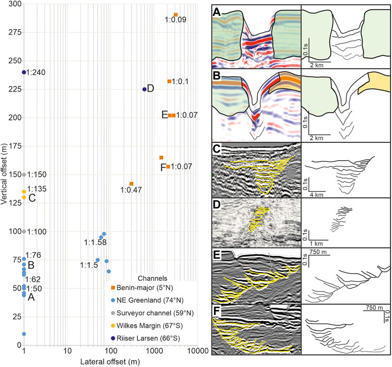
FIGURE 11. Comparison of vertical and lateral offset data plotted for 27 channel sections, with examples from NE Greenland shown in blue, Benin-Major (Deptuck et al., 2003, 2007), the Surveyor channel (Reece et al., 2011), the Wilkes Margin (Passchier et al., 2019) and the Riiser-Larsen Sea (Kuvaas et al., 2004). Examples (A–D) are from high latitude systems showing high vertical aggradation, and examples (E,F) from low latitude systems, showing a variety of lateral offsets. Lateral offset is measured by recording location of left-hand side channel floor in the basal cut, and measuring horizontal distance to the same location in the top cut – ratios of some systems are included. It is worth noting that channel systems showing no lateral offset may have offsets under the horizontal resolution of their respective datasets.
Current models, such as Peakall et al. (2000), Pirmez and Imran (2003), and Amos et al. (2010) outline sediment transport and depositional regimes in aggradational sinuous submarine channels, but do not take into account the effects of Coriolis forcing in high latitudes. Models incorporating Coriolis forcing (Cossu and Wells 2013; Cossu et al., 2015; Davarpanah Jazi et al., 2020) predict lateral migration of the entire system to the right in traction-dominated systems (in the Northern Hemisphere), and to the left in suspension-dominated systems (assuming that velocity and density are coupled). However, this does not take into account the presence of multiple flow types within a given system, or the ability of a flow to change down system. No current models account for the vertical aggradation seen in NE Greenland, with a variety of theoretical physical and climatic mechanisms proposed here. Here we examine a number of possible mechanisms.
5.3.1 Asymmetry of Coriolis force in successive bends
In straight channels where Coriolis forces dominate, a single secondary flow cell develops that is clockwise in the Northern hemisphere (looking downstream) and is constant along the length of the channel (Cossu et al., 2010). This is in sharp contrast to secondary flow cells in rivers and in low latitude submarine channels where there is a reversal in secondary flow between successive bends (Thorne et al., 1985; Keevil et al., 2006). This flipping of the flow cell between successive bends in rivers and low latitude submarine channel systems is crucial for amplifying any initial perturbation and thus enabling bend growth and increasing sinuosity (Johannesson and Parker, 1989; Peakall et al., 2007; Darby and Peakall, 2012). In the case of an initially straight channel dominated by Coriolis forces, small perturbations caused by localised deposition, bank collapse etc., may be too small to overcome the single clockwise directed secondary flow cell, and thus perturbations will not tend to amplify, restricting increases in sinuosity. Even in the case of a channel developing with low sinuosity where centrifugal forces begin to become more important, then there will be an asymmetry in forcing between bends. In left-turning bends in the Northern Hemisphere, Coriolis and centrifugal forces are complementary, and in right-turning bends they are opposed. Under these conditions, in a right-turning bend, Coriolis forces act to ‘damp’ the effects of centrifugal forces in systems with a Rossby number, RoW, <10 (Cossu and Wells, 2013; see also Davarpanah Jazi et al., 2020), again reducing the perturbations that lead to bend formation (Johannesson and Parker, 1989; Peakall et al., 2007; Cossu and Wells, 2010; Cossu and Wells, 2013; Darby and Peakall, 2012; Wei et al., 2013; Davarpanah Jazi et al., 2020). The presence of either a single secondary flow cell in systems where Coriolis forces are predicted to dominate, or an asymmetry in the influence of the centrifugal force between left- and right-turning bends where the lower part of the flow is not entirely dominated by Coriolis forces, act to damp the growth of perturbations and thus sinuosity growth.
Basal velocities might be expected to exhibit higher centrifugal forces and thus lower relative Coriolis forces than the bulk flow parameters derived from external levee height differentials (see Velocity estimates: Summary for these NE Greenland channels), and these basal velocities may be key to driving the development of sinuosity (e.g., Sylvester et al., 2013; Sylvester and Pirmez, 2019). However, such variations of downstream velocity in the vertical are also characteristic of experiments with bulk Rossby numbers <1 and yet these show consistent orientation of basal velocities and or erosion/tractional-deposition towards one side of the channel (Cossu and Wells, 2010; Cossu and Wells, 2013; Wells and Cossu, 2013; Davarpanah Jazi et al., 2020). The experimental results therefore suggest that flow with Rossby numbers less than one, based on external levee height differentials, likely act to reduce perturbations at the base of the flow. The estimated Rossby numbers strongly suggest therefore that these mechanisms for damping perturbations are likely to act within these Greenland channel systems.
5.3.2 Influence of mixed flow types upon flow processes within channels
Glacially-influenced continental margins experience a wide range of sedimentary processes, dependent on ice location, hinterland geology and ice cyclicity (Jaeger and Koppes, 2016), with vast amounts of sediments generated and conveyed to deep-water systems (Laberg and Vorren, 1996), exhibiting a wide range of grain-sizes (Ó Cofaigh et al., 2004). Cores from the Greenland channel-axes and their associated overbank successions report a range from ‘pebbly coarse sand’, to mud factions (Ó Cofaigh et al., 2004), indicating either a combination of traction- and suspension-dominated flows are transported down the channel, or strongly stratified flows capable of transporting material as bedload. Current physical models only examine the effects of one flow type upon process regimes and resultant sedimentary architecture (Cossu and Wells, 2013; Cossu et al., 2015). However, systems have been shown to transport both traction- and suspension-dominated flows, e.g., NAMOC (Hesse et al., 2001; Piper and Normark, 2009). A balance between these two flow types (or components), which individually cause opposing migration directions when deflected by Coriolis forces (Cossu and Wells, 2013), or a strongly stratified flow, could result in vertical stacking of sedimentary deposits (Kane et al., 2008; Amos et al., 2010). Small lateral offsets may result from the higher frequency of one flow in relation to the other. For example, in Figure 7G a slight migration to the right may indicate a higher frequency of traction-dominated flows, than suspension-dominated flows, or a greater proportion of the flow may be traction-dominated in the case of stratified flows.
Occasional exceptionally large outburst-related flows (e.g., Piper et al., 2007, 2012) might also be postulated to affect channel geometry, sinuosity and migration patterns. Erosional valley-widening events that punctuate sustained periods of external levee growth have been observed on the Laurentian Fan and linked to such outsized flows (Skene and Piper, 2006; Piper et al., 2007). Such widening events are not observed in the Greenland channels studied herein, perhaps reflecting the filtering effects of strongly aggradational channels that tend to ‘tune’ outsized flows down to a characteristic flow scale (Amos et al., 2010). Consequently, there is no evidence for exceptionally large flows playing a major morphological role in the studied channel systems.
5.3.3 Effects of rapid aggradation and quasi-channelisation
As noted glacial systems are capable of generating large volumes of sediment. For example, Laberg and Vorren (1996) report sedimentation rates of up to 1.72 m/kyr−1 from the Barents Sea. These high rates of sediment supply could result in rapid aggradation of overbank material. Lateral migration in submarine channels is linked to bend growth during the initial phase of channel development (Peakall et al., 2000; Sylvester et al., 2011; Jobe et al., 2016), with stable planform geometries and vertical aggradation characteristic of the ‘equilibrium’ phase, where the channel acts predominantly as a bypass conduit (Peakall et al., 2000). If overbank sedimentation predominates within a system then rapid external levee growth may occur (Straub et al., 2012). If as observed herein, Coriolis forcing is important, then partitioning of flows, and deposition on the right-hand side (in the Northern Hemisphere) would dominate from the first event. Once external levees are constructed, in-channel sedimentation that is able to keep pace with overbank deposition has been shown to create vertically aggrading channel-fill (Mohrig and Buttles, 2007; Straub et al., 2012). It is unclear why the channel banks do not undergo subsequent erosion, thus generating perturbations, which are naturally reinforced, leading to bend growth. However, this may be due to gelling and consolidation of clay, which cause the shear stress needed to erode channel banks to be far higher than that required for deposition (Mehta et al., 1989; Fenies and Faugres, 1998; Smith, 1998), as postulated by Peakall et al. (2000); see also Asymmetry of Coriolis force in successive bends. A non-migrating channel would then create increasingly stable external levees, further ‘fixing’ the channel in place, as seen in the later stages of NAMOC (Klaucke et al., 1998) and in low latitude systems (e.g., Kane et al., 2008; Straub et al., 2008; Amos et al., 2010).
Several studies indicate that weakly confined flows, which are initially able to deposit large volumes of material in the overbank region, are related to vertical aggradation of channel-fill (Mohrig and Buttles, 2007; Straub et al., 2012). Less confinement also inhibits point bar development, preventing meander formation and expansion (Kane et al., 2008). If planform morphology and vertical aggradation are linked, then the lack of bend expansion and propagation through quasi-confinement of flows may be another factor. The dominance of Coriolis forcing over centrifugal forces, causing deflection of flows and preferential deposition, may therefore result in a rapid transition to the aggradational equilibrium phase, and preclude widespread bend development and lateral migration.
5.4 A new model for high latitude submarine channel evolution
The observations and interpretations above are combined into a three-stage model for submarine channels, examining the role of physical and climatic forcing upon the evolution and architecture of high latitude channel systems. Coriolis forcing is a latitudinally dependent factor; the relative influence increases with latitude, affecting channel sedimentation patterns. In contrast, sediment flux and calibre can vary depending on the stage of glacial cyclicity, resulting in a wide range of flows and sediment types transported through the system.
The initial stages of channel system evolution (Figure 12A) follow a similar pattern to low latitude systems; frontal lobes are deposited that heal relief generated by mass transport complexes, and are incised by subsequent flows as channel-levee systems propagate basinward. Coriolis forces are able to deflect these flows to the right (in the Northern Hemisphere), resulting in preferential deposition of overbank material, guiding the path of subsequent flows and creating a low sinuosity channel planform (Figures 12B,C). Furthermore, initial bend formation is suppressed through the effects of Coriolis forcing upon secondary flows cells, preventing initial perturbations in the flow field. The interplay of inner-bank deposition and outer-bank erosion thought to be responsible for bend amplitude growth (Peakall et al., 2000) is further inhibited by the occurrence of traction and suspension-dominated flows within the system. The influence of Coriolis forcing upon each of these flow types causes opposing (but one-sided) patterns of deposition or erosion (Figure 12D) (Cossu et al., 2015; Davarpanah Jazi et al., 2020). Rapid levee and intrachannel aggradation could also inhibit bend formation and growth, as well as generating vertical stacking of channel-fill (Figure 12C). The latter stages of channel development (Figure 12C) exhibit strongly asymmetric external levees, preventing lateral channel migration, reinforcing a low-sinuosity planform morphology, and promoting vertical aggradation. The presence of both traction- and suspension-dominated deposits, and their opposing depositional patterns, further promotes vertical aggradation (Figure 12D). Coriolis forcing results in preferential deposition along one side of the channel (Cossu and Wells, 2013; Davarpanah Jazi et al., 2020), possibly resulting in enhanced external levee aggradation, with the height of these creating a stable conduit during early channel development, allowing for vertical aggradation. This suggests that a low sinuosity planform morphology, vertically aggrading channel-fill, and large external levees are all related to the same process controls.
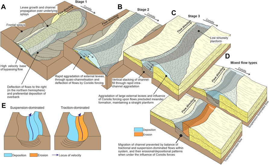
FIGURE 12. Model for evolution of high latitude channel systems. Stage 1 (A) shows early stages of channel propagation, with system incising frontal splays, and small levees present in up-dip sections; if flow velocities are low, then Coriolis forcing may result in preferential splay deposition on the right-hand side. Stage 2 (B) represents a more mature system, with Coriolis forcing able to deflect flows to the right-hand side, resulting in asymmetrical levee growth. In the later stages of system evolution (C), the channel is ‘fixed’ in place, with large external levees preventing lateral migration – creating vertical stacking of channel fill. Mixed flow types may also be responsible for vertical stacking (D), with work by Cossu et al. (2015) predicting different migration directions for traction and suspension-dominated flows (E), modified from Cossu et al., 2015), the interplay of which could result in an overall vertical pattern.
The key differences between this high-latitude model and low-latitude systems are shown schematically in Figure 13. Axial channel deposits have markedly different geometries, and levees are much larger relative to the channel and more consistently asymmetric along one side of the channel in high-latitude channel-levee systems. These differences in architecture will also be reflected in terms of facies, where high-latitude systems will largely lack the point-bar deposits and overlying finer-grained deposits at the inside of bends, so-called ‘oblique accretion deposits’ (Straub et al., 2011; Peakall and Sumner, 2015), characteristic of low-latitude systems. Where such point-bar and oblique accretion deposits are present they may be focused on bends that have enhanced sinuosity (see Figure 6 for possible examples) or where external forcing (levee collapse; tectonism) lead to bend migration, and even in such examples more limited bend migration may make them less areally extensive. Whilst these are idealised end-member models, it is useful to note that a number of features from high latitude systems may be present in some mid-latitude systems. It has previously been noted that the channels of the Rhone Fan exhibit asymmetry in overbank successions (Torres et al., 1997), and systems in the Huntingdon Field of the North Sea exhibit asymmetrical facies distributions interpreted to be a function of Coriolis forcing (Edwards et al., 2018).
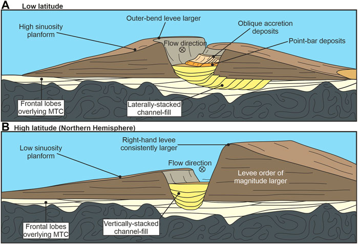
FIGURE 13. Schematic diagram of architectural differences between high and low latitude channel-levee systems. (A) Low latitude systems exhibit frontal lobes deposited over MTD deposits (Posamentier and Kolla, 2003), overlain by a channel-levee system with higher levees on outer bends, with symmetrical levees on straighter sections, ‘J-shaped’ channel fill geometries (Jobe et al., 2016), inner-bank deposition and a high-sinuosity planform. (B) High latitude channel levee systems are characterised by deposition of frontal lobe deposits over an MTD, followed by asymmetrical levees (right-hand levee higher in the Northern Hemisphere, left-hand levee higher in the Southern Hemisphere) that can be over an order of magnitude larger than low latitude systems), and vertical stacking of channel fill.
The model presented here for channel-levee systems, based on these NE Greenland channels, and comparison to similar high-latitude systems, demonstrates that it is not solely the presence of deep-ocean channels such as NAMOC (e.g., Klaucke et al., 1997) and NP-28 (Boggild and Mosher, 2021) that are responsible for low sinuosity channels in high-latitudes (cf. Sylvester and Pirmez, 2019). The NE Greenland channels exhibit tributive systems in their upper reaches, in common with many glacial channel systems, with these suggested to be important for planform morphology, and thus sedimentary architecture (Sylvester and Pirmez, 2019). However, it is not clear mechanistically, how such tributive systems influence channel planform morphology and architecture. Presumably, they may lead to a greater range of input points and flow stages than in equivalent single point systems. Yet once downstream of these tributaries, flows greater than channel depth in the main channel will undergo reduction in size through overspill and flow stripping (flow ‘tuning’) so that flows reduce to a characteristic size (Amos et al., 2010). Alternatively, the tributive inputs may lead to a larger number of smaller flows that traverse the channel without overspilling. However, by analogy with rivers, channel morphology is dominantly related to ‘bankfull’ discharges (Wolman and Miller, 1960), and so it is not clear that more frequent, small flows below ‘bankfull’ will be important in influencing channel morphology and architecture. It is also not clear how a wider range of flow sizes would lead to vertical aggradation of channels. Given that tributive networks in upper reaches are characteristic of high-latitude channels then their potential influence needs further research, but at present mechanistic arguments for their influence on channel morphology are lacking.
5.5 Implications for palaeoenvironmental records
The great thickness of external levees in high-latitude systems (Figures 10, 13), representing highly efficient flow stripping and overspill of flows, will form ideal archives of palaeoenvironmental change offshore from glaciated margins. It is recommended that these successions are targeted as records for future research drilling expeditions, as for instance has been undertaken in International Ocean Discovery Programme Expedition 374 to the eastern Ross Sea continental slope, Antarctica (e.g., Conte et al., 2021; King et al., 2022). Consequently, this overspill and deposition of fines will lead to an effective narrowing of grain-size deposited within the channel. Therefore, even the initially broad grain-size distributions from glacially-fed systems are predicted to be effectively segregated through the channel-levee system to form sand-rich lobe complexes.
6 Conclusion
This work presents a new study on temporal and spatial variations in sedimentary processes, depositional architecture and evolution from high latitude submarine channel-levee systems, integrating bathymetry, GLORIA side scan, and seismic reflection data. The NE Greenland systems are low gradient, low sinuosity, glacially-influenced channels – indicating the need for a revision of current classification schemes. Furthermore, models of depositional architecture and flow processes are predominantly based on studies from low- and mid-latitude settings. Subsurface imaging shows that long-term evolution of channel-levee systems exhibit notable similarities to their low latitude counterparts, such as propagation of channel-levee systems over frontal lobes. However, the resultant architecture differs in a number of ways, most notably: 1) external levees are asymmetric, and very large; 2) channel-fills exhibit little to no lateral migration at any stage of channel evolution; and 3) the channel system exhibits very low sinuosity (peak sinuosity = 1.3) on a low gradient slope. This likely results from a number of latitudinally dependent factors, both physical (Coriolis forcing) and climatic (sediment calibre and flow type), and a number of process-based mechanisms are proposed to explain these architectural variations.
To assess the susceptibility of the system to Coriolis forcing, a range of Rossby numbers have been calculated, indicating Coriolis forces have a strong influence at all locations, and is the dominant control on system morphology in most measured locations. Preferential deposition is evident with large, asymmetric external levees bounding the system. Development of large external levees along one side of a straight channel section is possible through the interplay of Coriolis forcing and high sediment delivery during glacial intervals, with tilting of the density interface and continuous preferential deposition resulting in rapid aggradation and stabilisation of early external levees. Vertical stacking of component channel-fill is unrelated to contourite or structural influences and is postulated to be related to mixed flow types within the system, and the interaction of these flows with Coriolis forces causing alternating phases of preferential erosion and deposition, restricting lateral migration. Development of a secondary flow cell with constant orientation along the length of the channel as a result of Coriolis forcing does not allow for the amplification of initial flow perturbations that lead to bend formation. Furthermore, Coriolis forces act to ‘damp’ the effects of centrifugal forces in right-turning bends, reducing perturbations that lead to bend growth. A lack of bend growth and large, stable external levees could prevent channel migration, and result in vertical stacking of channel-fills. The resultant latitudinal architectural variation has implications for reservoir quality and distribution. Highly effective stripping of flows into the overbank also suggests that high latitude levees contain excellent palaeoenvironmental records, as well as segregating grain-size along system.
Data availability statement
The raw data supporting the conclusions of this article will be made available by the authors, without undue reservation.
Author contributions
CA led the work, undertook the analysis, led the writing and produced the figures. JP, DH, WB, and AB contributed to the discussion of the results and contributed to the writing of the manuscript.
Funding
CA was supported by a NERC (Natural Environment Research Council) PhD studentship (NE/L002574/1).
Acknowledgments
The authors would like to thank TGS and AWI for permission to publish this seismic dataset, to AWI for collection and processing, and to TGS for support. We thank David Piper for his insightful comments on a previous version of this manuscript. We also thank the two reviewers Michael Lazar and Michele Rebesco, for their very helpful comments, and the Editor Hajime Naruse for his help.
Conflict of interest
Author WB was employed by TGS.
The remaining authors declare that the research was conducted in the absence of any commercial or financial relationships that could be construed as a potential conflict of interest.
Publisher’s note
All claims expressed in this article are solely those of the authors and do not necessarily represent those of their affiliated organizations, or those of the publisher, the editors and the reviewers. Any product that may be evaluated in this article, or claim that may be made by its manufacturer, is not guaranteed or endorsed by the publisher.
References
Akhmetzhanov, A., Kenyon, N. H., Habgood, E., Van Der Mollen, A. S., Nielsen, T., Ivanov, M., et al. (2007). “North Atlantic contourite sand channels,” in Economic and palaeoceanographic significance of contourite deposits. Editors A. R. Viana, and M. Rebesco (Bath, UK: Geological Society, London, Special Publication), 276, 25–47. doi:10.1144/GSL.SP.2007.276.01.02
Amos, K. J., Peakall, J., Bradbury, P. W., Roberts, M., Keevil, G., and Gupta, S. (2010). The influence of bend amplitude and planform morphology on flow and sedimentation in submarine channels. Mar. Petroleum Geol. 27, 1431–1447. doi:10.1016/j.marpetgeo.2010.05.004
Andrews, J. T., Jennings, A. E., Cooper, T., Williams, K. M., and Mienert, J. (1996). “Late Quaternary sedimentation along a fjord to shelf (trough) transect, East Greenland (68°N),” in Late quaternary paleoceanography of the north atlantic margins. Editors J. T. Andrews, W. E. N. Austin, H. Bergsten, and A. E. Jennings (Bath, UK: Geological Society, London, Special Publication), 111, 153–166.
Babonneau, N., Savoye, B., Cremer, M., and Klein, B. (2002). Morphology and architecture of the present canyon and channel system of the Zaire deep-sea fan. Mar. Petroleum Geol. 19, 445–467. doi:10.1016/s0264-8172(02)00009-0
Babonneau, N., Cattaneo, A., Savoye, B., Barjavel, G., Deverchere, J., and Yelles, K. (2012). “The kramis deep-sea fan off Western Algeria: Role of sediment waves in turbiditic levee growth,” in Application of the principles of seismic geomorphology to continental-slope and base-of-slope systems: Case studies from seafloor and near-seafloor analogues. Editors B. E. Prather, M. E. Deptuck, D. Mohrig, B. Van Hoorn, and R. B. Wynn (Tulsa, Oklahoma: SEPM Special Publication), 99, 293–308.
Beaubouef, R., Rossen, C., and Lovell, R. (2007). “The beacon channel: A newly recognized architectural type in the brushy canyon formation, Texas, USA,” in Atlas of deepwater outcrops. Editors G. S. Steffens, T. H. Nilsen, J. R. J. Studlick, and R. D. Shew (Tulsa, Oklahoma: AAPG Studies in Geology), 56, 432–443.
Berger, D., and Jokat, W. (2008). A seismic study along the East Greenland margin from 72°N to 77°N. Geophys. J. Int. 174, 733–748. doi:10.1111/j.1365-246X.2008.03794.x
Boggild, K. (2016). Morphological examination of the NP-28 submarine channel-fan complex in the Amundsen Basin. Halifax, Nova Scotia: Unpublished MSc Thesis, Dalhousie University, 64.
Boggild, K., and Mosher, D. C. (2021). Turbidity currents at polar latitudes: A case study of NP-28 channel in the amundsen basin, Arctic Ocean. Mar. Geol. 440, 106571. doi:10.1016/j.margeo.2021.106571
Bourget, J., Zaragosi, S., Garlan, T., Gabelotaud, I., Guyomard, P., Dennielou, B., et al. (2008). Discovery of a giant deep-sea valley in the Indian ocean, off eastern africa: The Tanzania channel. Mar. Geol. 255, 179–185. doi:10.1016/j.margeo.2008.09.002
Bowen, A. J., Normark, W. R., and Piper, D. J. W. (1984). Modelling of turbidity currents on navy submarine fan, California continental borderland. Sedimentology 31, 169–185. doi:10.1111/j.1365-3091.1984.tb01957.x
Brice, J. C. (1974). Evolution of meander loops. Geol. Soc. Am. Bull. 85, 581–586. doi:10.1130/0016-7606(1974)85<581:eoml>2.0.co;2
Brunt, R., McCaffrey, W., and Butler, R. (2007). “Setting and architectural elements of the champsaur sandstone, France,” in Atlas of deepwater outcrops. Editors G. S. Steffens, T. H. Nilsen, J. R. J. Studlick, and R. D. Shew (Tulsa, Oklahoma: AAPG Studies in Geology), 56, 188–191.
Buckee, C., Kneller, B., and Peakall, J. (2001). “Turbulence structure in steady solute-driven gravity currents,” in Particulate gravity currents. Editors W. D. McCaffrey, B. C. Kneller, and J. Peakall (Oxford: International Association of Sedimentologists, Special Publication), 31, 173–188.
Butterworth, P., and Macdonald, D. (2007). “Channel-levee complexes of the fossils bluff group, Antarctica,” in Atlas of deepwater outcrops. Editors G. S. Steffens, T. H. Nilsen, J. R. J. Studlick, and R. D. Shew (Tulsa, Oklahoma: AAPG Studies in Geology), 56, 36–41.
Campbell, D. C., and Mosher, D. C. (2016). Geophysical evidence for widespread Cenozoic bottom current activity from the continental margin of Nova Scotia, Canada. Mar. Geol. 378, 237–260. doi:10.1016/j.margeo.2015.10.005
Chough, S., and Hesse, R. (1976). Submarine meandering thalweg and turbidity, currents flowing for 4,000 km in the northwest atlantic Mid-Ocean channel, labrador sea. Geol. 4, 529–533. doi:10.1130/0091-7613(1976)4<529:SMTATC>2.0.CO;2
Clare, M. A., Talling, P. J., Challenor, P., Malgesini, G., and Hunt, J. (2014). Distal turbidites reveal a common distribution for large (>0.1 km3) submarine landslide recurrence. Geology 42, 263–266. doi:10.1130/g35160.1
Clark, J. D., Kenyon, N. H., and Pickering, K. T. (1992). Quantitative analysis of the geometry of submarine channels: Implications for the classification of submarine fans. Geol. 20, 633–636. doi:10.1130/0091-7613(1992)020<0633:QAOTGO>2.3.CO;2
Clark, J. D., and Pickering, K. T. (1996). Architectural elements and growth patterns of submarine channels: Applications to hydrocarbon exploration. Am. Assoc. Petroleum Geol. Bull. 80, 194–221.
Conte, R., Rebesco, M., De Santis, L., Colleoni, F., Bensi, M., Bergamasco, A., et al. (2021). Bottom current control on sediment deposition between the Iselin Bank and the Hillary Canyon (Antarctica) since the late Miocene: An integrated seismic-oceanographic approach. Deep Sea Res. Part I Oceanogr. Res. Pap. 176, 103606. doi:10.1016/j.dsr.2021.103606
Corney, R. K. T., Peakall, J., Parsons, D. R., Elliott, L., Amos, K. J., Best, J. L., et al. (2006). The orientation of helical flow in curved channels. Sedimentology 53, 249–257. doi:10.1111/j.1365-3091.2006.00771.x
Cossu, R., and Wells, M. G. (2010). Coriolis forces influence the secondary circulation of gravity currents flowing in large-scale sinuous submarine channel systems. Geophys. Res. Lett. 37, L17603. doi:10.1029/2010gl044296
Cossu, R., Wells, M. G., and Peakall, J. (2015). Latitudinal variations in submarine channel sedimentation patterns : The role of Coriolis forces. J. Geol. Soc. Lond. 172, 161–174. doi:10.1144/jgs2014-043
Cossu, R., and Wells, M. G. (2013). The evolution of submarine channels under the influence of Coriolis forces: Experimental observations of flow structures. Terra nova. 25, 65–71. doi:10.1111/ter.12006
Cossu, R., Wells, M. G., and Wahlin, A. K. (2010). Influence of the Coriolis force on the velocity structure of gravity currents in straight submarine channel systems. J. Geophys. Res. 115 (11), C11016. doi:10.1029/2010JC006208
Covault, J. A., Kostic, S., Paull, C. K., Sylvester, Z., and Fildani, A. (2017). Cyclic steps and related supercritical bedforms: Building blocks of deep-water depositional systems, Western north America. Mar. Geol. 393, 4–20. doi:10.1016/j.margeo.2016.12.009
Cronin, B., Celik, H., Hurst, A., Gul, M., Gurbuz, K., Mazzini, A., et al. (2007). “Slope-channel complex fill and overbank architecture, Tinker channel, Kirkgecit Formation, Turkey,” in Atlas of deepwater outcrops. Editors G. S. Steffens, T. H. Nilsen, J. R. J. Studlick, and R. D. Shew (Tulsa, Oklahoma: AAPG Studies in Geology), 56, 363–367.
Damuth, J., Flood, R., Kowsmann, R., Belderson, R., and Gorini, M. (1988). Anatomy and growth pattern of Amazon deep-sea fan as revealed by long-range side-scan sonar (GLORIA) and high-resolution seismic studies. Am. Assoc. Petroleum Geol. Bull. 72, 885–911.
Darby, S. E., and Peakall, J. (2012). Modelling the equilibrium bed topography of submarine meanders that exhibit reversed secondary flows. Geomorphology 163-164, 99–109. doi:10.1016/j.geomorph.2011.04.050
Davarpanah Jazi, S., Wells, M. G., Peakall, J., Dorrell, R. M., Thomas, R. E., Keevil, G. M., et al. (2020). Influence of Coriolis force upon bottom boundary layers in a large-scale gravity current experiment: Implications for evolution of sinuous deep-water channel systems. JGR. Oceans 125, e2019JC015284. doi:10.1029/2019JC015284
Deptuck, M. E., Steffens, G. S., Barton, M., and Pirmez, C. (2003). Architecture and evolution of upper fan channel-belts on the Niger Delta slope and in the Arabian Sea. Mar. Petroleum Geol. 20, 649–676. doi:10.1016/j.marpetgeo.2003.01.004
Deptuck, M. E., Sylvester, Z., Pirmez, C., and O’Byrne, C. (2007). Migration-aggradation history and 3-D seismic geomorphology of submarine channels in the Pleistocene Benin-major Canyon, Western Niger Delta slope. Mar. Petroleum Geol. 24, 406–433. doi:10.1016/j.marpetgeo.2007.01.005
Dorrell, R. M., Darby, S. E., Peakall, J., Sumner, E. J., Parsons, D. R., and Wynn, R. B. (2013). Superelevation and overspill control secondary flow dynamics in submarine channels. J. Geophys. Res. Oceans 118, 3895–3915. doi:10.1002/jgrc.20277
Dorrell, R. M., Peakall, J., Burns, C., and Keevil, G. M. (2018). A novel mixing mechanism in sinuous seafloor channels: Implications for submarine channel evolution. Geomorphology 303, 1–12. doi:10.1016/j.geomorph.2017.11.008
Døssing, A., Japsen, P., Watts, A. B., Nielsen, T., Jokat, W., Thybo, H., et al. (2016). Miocene uplift of the NE Greenland margin linked to plate tectonics: Seismic evidence from the Greenland Fracture Zone, NE Atlantic. Tectonics 35, 257–282. doi:10.1002/2015tc004079
Dowdeswell, J. A., Elverhøi, A., and Spielhagen, R. (1998). Glacimarine sedimentary processes and facies on the Polar North Atlantic margins. Quat. Sci. Rev. 17, 243–272. doi:10.1016/S0277-3791(97)00071-1
Dowdeswell, J. A., Ó Cofaigh, C., Taylor, J., Kenyon, N. H., Mienert, J., and Wilken, M. (2002). “On the architecture of high-latitude continental margins: The influence of ice-sheet and sea- ice processes in the polar North Atlantic,” in Glacier influenced sedimentation on high-latitude continental margins. Editors J. A. Dowdeswell, and C. Ó Cofaigh (Bath, UK: Geological Society, London, Special Publications), 203, 33–54.
Dowdeswell, J. A., Evans, J., and Ó Cofaigh, C. (2010). Submarine landforms and shallow acoustic stratigraphy of a 400 km-long fjord-shelf-slope-transect, Kangerlussuaq margin, East Greenland. Quat. Sci. Rev. 29, 3359–3369. doi:10.1016/j.quascirev.2010.06.006
Edwards, C., McQuaid, S., Easton, S., Scott, D., Couch, A., Evans, R., et al. (2018). “Lateral accretion in a straight slope channel system: An example from the forties sandstone of the huntington field, UK central North Sea,” in Petroleum Geology of NW Europe: 50 Years of learning – Proceedings of the 8thpetroleum geology conference. Editors M. Bowman, and B. Levell, 413–428.
Evans, J., Dowdeswell, J. A., Grobe, H., Niessen, F., Stein, R., Hubberten, H.-W., et al. (2002). “Late quaternary sedimentation in kejser Franz joseph fjord and the continental margin of east Greenland,” in Glacier influenced sedimentation on high-latitude continental margins. Editors J. A. Dowdeswell, and C. Ó Cofaigh (Bath, UK: Geological Society, London, Special Publications), 203, 149–179. doi:10.1144/GSL.SP.2002.203.01.09
Evans, J., Ó Cofaigh, C., Dowdeswell, J. A., and Wadhams, P. (2009). Marine geophysical evidence for former expansion and flow of the Greenland Ice Sheet across the north-east Greenland continental shelf. J. Quat. Sci. 23, 279–293. doi:10.1002/jqs.1231
Ezz, H., Cantelli, A., and Imran, J. (2013). Experimental modeling of depositional turbidity currents in a sinuous submarine channel. Sediment. Geol. 290, 175–187. doi:10.1016/j.sedgeo.2013.03.017
Ezz, H., and Imran, J. (2014). Curvature-induced secondary flow in submarine channels. Environ. Fluid Mech. (Dordr). 14, 343–370. doi:10.1007/s10652-014-9345-4
Fenies, H., and Faugres, J-C. (1998). Facies and geometry of tidal channel-fill deposits (Arcachon Lagoon, SW France). Mar. Geol. 150, 131–148. doi:10.1016/s0025-3227(98)00049-8
Figueiredo, J. J. P., Hodgson, D., Flint, S. S., and Kavanagh, J. (2010). Depositional environments and sequence stratigraphy of an exhumed Permian mudstone-dominated submarine slope succession, Karoo Basin, South Africa. J. Sediment. Res. 80, 97–118. doi:10.2110/jsr.2010.002
Fildani, A., Normark, W. R., Kostic, S., and Parker, G. (2006). Channel formation by flow stripping: Large-scale scour features along the monterey east channel and their relation to sediment waves. Sedimentology 53, 1265–1287. doi:10.1111/j.1365-3091.2006.00812.x
Flint, S. S., Hodgson, D. M., Sprague, A. R., Brunt, R. L., Van der Merwe, W. C., Figueiredo, J., et al. (2011). Depositional architecture and sequence stratigraphy of the Karoo basin floor to shelf edge succession, Laingsburg depocentre, South Africa. Mar. Petroleum Geol. 28, 658–674. doi:10.1016/j.marpetgeo.2010.06.008
Flood, R. D., and Damuth, J. E. (1987). Quantitative characteristics of sinuous distributary channels on the Amazon Deep-Sea Fan. Geol. Soc. Am. Bull. 98, 728–738. doi:10.1130/0016-7606(1987)98<728:qcosdc>2.0.co;2
Flood, R. D., Manley, P. L., Kowsmann, R. O., Appi, C. J., and Pirmez, C. (1991). “Seismic facies and late quaternary growth of amazon submarine fan,” in Seismic facies and sedimentary processes of submarine fans and turbidite systems. Editors P. Weimer, and M. H. Link (New York: Springer), 415–433.
Funder, S., and Hansen, L. (1996). The Greenland ice sheet - a model for its culmination and decay during and after the Last Glacial Maximum. bgsd. 42, 137–152. doi:10.37570/bgsd-1995-42-12
Gamberi, F., and Rovere, M. (2011). Architecture of a modern transient slope fan (Villafranca fan, Gioia basin - southeastern Tyrrhenian Sea). Sediment. Geol. 236, 211–225. doi:10.1016/j.sedgeo.2011.01.007
Gamberi, F., Rovere, M., Dykstra, M., Kane, I. A., and Kneller, B. C. (2013). Integrating modern seafloor and outcrop data in the analysis of slope channel architecture and fill. Mar. Petroleum Geol. 41, 83–103. doi:10.1016/j.marpetgeo.2012.04.002
Gamboa, D., Alves, T. M., and Cartwright, J. (2011). Distribution and characterization of failed (mega) blocks along salt ridges, southeast Brazil: Implications for vertical fluid flow on continental margins. J. Geophys. Res. 116, B08103. doi:10.1029/2011jb008357
García, M., Alonso, B., Ercilla, G., and Gràcia, E. (2006). The tributary valley systems of the almeria canyon (alboran sea, SW mediterranean): Sedimentary architecture. Mar. Geol. 226, 207–223. doi:10.1016/j.margeo.2005.10.002
García, M., Dowdeswell, J. A., Ercilla, G., and Jakobsson, M. (2012). Recent glacially influenced sedimentary processes on the East Greenland continental slope and deep Greenland Basin. Quat. Sci. Rev. 49, 64–81. doi:10.1016/j.quascirev.2012.06.016
García, M., Batchelor, C. L., and Ó Cofaigh, C. (2016). “A glacier-influenced turbidite system and associated landform assemblage in the Greenland Basin and adjacent continental slope,” in Atlas of submarine glacial landforms: Modern, quaternary and ancient. Editors J. A. Dowdeswell, M. Canals, M. Jakobsson, B. J. Todd, E. K. Dowdeswell, and K. A. Hogan (Bath, UK: Geological Society London Memoirs), 46, 461–468. doi:10.1144/m46.148
Garcia, M. H. (1994). Depositional turbidity currents laden with poorly sorted sediment. J. Hydraul. Eng. 120, 1240–1263. doi:10.1061/(asce)0733-9429(1994)120:11(1240)
Gibbs, R. J., Matthews, M. D., and Link, D. A. (1971). The relationship between sphere size and settling velocity. J. Sediment. Res. 41, 7–18.
Gong, C., Wang, Y., Zhu, W., Li, W., and Xu, Q. (2013). Upper Miocene to quaternary unidirectionally migrating deep-water channels in the pearl river mouth basin, northern south China sea. Am. Assoc. Pet. Geol. Bull. 97, 285–308. doi:10.1306/07121211159
Gong, C., Wang, Y., Steel, R. J., Peakall, J., Zhao, X., and Sun, Q. (2016). Flow processes and sedimentation in unidirectionally migrating deep-water channels: From a three-dimensional seismic perspective. Sedimentology 63, 645–661. doi:10.1111/sed.12233
Gould, H. R. (1951). “Some quantitative aspects of Lake Mead turbidity currents,” in Turbidity currents and the transportation of coarse sediments to deep water. Editor J. L. Hough (Tulsa, Oklahoma: Society of Economic Paleontologists and Mineralogists Special Publication), 2, 34–52.
Hakansson, L., Alexanderson, H., Hjort, C., Moller, P., Briner, J. P., Aldahan, A., et al. (2009). Late Pleistocene glacial history of Jameson Land, central East Greenland, derived from cosmogenic 10Be and 26Al exposure dating. Boreas 38, 244–260. doi:10.1111/j.1502-3885.2008.00064.x
Hakansson, L., Briner, J., Alexanderson, H., Aldahan, A., and Possnert, G. (2007). 10Be ages from central east Greenland constrain the extent of the Greenland ice sheet during the Last Glacial Maximum. Quat. Sci. Rev. 26, 2316–2321. doi:10.1016/j.quascirev.2007.08.001
Hansen, L. A. S., Callow, R. H. T., Kane, I. A., Gamberi, F., Rovere, M., Cronin, B. T., et al. (2015). Genesis and character of thin-bedded turbidites associated with submarine channels. Mar. Petroleum Geol. 67, 852–879. doi:10.1016/j.marpetgeo.2015.06.007
Hansen, L., Janocko, M., Kane, I., and Kneller, B. (2017). Submarine channel evolution, terrace development, and preservation of intra-channel thin-bedded turbidites: Mahin and Avon channels, offshore Nigeria. Mar. Geol. 383, 146–167. doi:10.1016/j.margeo.2016.11.011
Hesse, R., Klaucke, I., Khodabakhsh, S., Piper, D. J. W., and Ryan, W. B. F. (2001). Sandy submarine braid plains: Potential deep-water reservoirs. Am. Assoc. Pet. Geol. Bull. 85, 1499–1521. doi:10.1306/8626CAEB-173B-11D7-8645000102C1865D
Hjort, C. (1997). Glaciation, climate history, changing marine levels and the evolution of the north-east water polynya. J. Mar. Syst. 10, 23–33. doi:10.1016/s0924-7963(96)00068-1
Hodgson, D. M., Kane, I. A., Flint, S. S., Brunt, R. L., and Ortiz-Karpf, A. (2016). Time-transgressive confinement on the slope and the progradation of basin-floor fans: Implications for the sequence stratigraphy of deep-water deposits. J. Sediment. Res. 86, 73–86. doi:10.2110/jsr.2016.3
Huang, X., Gohl, K., and Jokat, W. (2014). Variability in Cenozoic sedimentation and paleo-water depths of the Weddell Sea basin related to pre-glacial and glacial conditions of Antarctica. Glob. Planet. Change 118, 25–41. doi:10.1016/j.gloplacha.2014.03.010
Huang, X., and Jokat, W. (2016). Middle Miocene to present sediment transport and deposits in the southeastern Weddell Sea, Antarctica. Glob. Planet. Change 139, 211–225. doi:10.1016/j.gloplacha.2016.03.002
Hübscher, C., Spieß, V., Breitzke, M., and Weber, M. (1997). The youngest channel-levee system of the bengal fan: Results from digital sediment echo-sounder data. Mar. Geol. 141, 125–145. doi:10.1016/s0025-3227(97)00066-2
Jaeger, J. M., and Koppes, M. N. (2016). The role of the cryosphere in source-to-sink systems. Earth-Science Rev. 153, 43–76. doi:10.1016/j.earscirev.2015.09.011
Jakobsson, M., Mayer, L. A., Bringensparr, C., Castro, C. F., Mohammad, R., Johnson, P., et al. (2020). The international bathymetric Chart of the Arctic Ocean version 4.0. Sci. Data 7 (176). doi:10.1038/s41597-020-0520-9
Janocko, M., Nemec, W., Henriksen, S., and Warchol, M. (2013). The diversity of deep-water sinuous channel belts and slope valley-fill complexes. Mar. Petroleum Geol. 41, 7–34. doi:10.1016/j.marpetgeo.2012.06.012
Jobe, Z. R., Howes, N. C., and Auchter, N. C. (2016). Comparing submarine and fluvial channel kinematics: Implications for stratigraphic architecture. Geology 44, 931–934. doi:10.1130/G38158.1
Jobe, Z. R., Lowe, D. R., and Uchytil, S. J. (2011). Two fundamentally different types of submarine canyons along the continental margin of Equatorial Guinea. Mar. Petroleum Geol. 28, 843–860. doi:10.1016/j.marpetgeo.2010.07.012
Johannesson, H., and Parker, G. (1989). Secondary flow in mildly sinuous channel. J. Hydraul. Eng. 115, 289–308. doi:10.1061/(asce)0733-9429(1989)115:3(289)
Kane, I. A., Kneller, B. C., Dykstra, M., Kassem, A., and McCaffrey, W. D. (2007). Anatomy of a submarine channel-levee: An example from upper cretaceous slope sediments, rosario formation, baja California, Mexico. Mar. Petroleum Geol. 24, 540–563. doi:10.1016/j.marpetgeo.2007.01.003
Kane, I. A., McCaffrey, W. D., and Peakall, J. (2008). Controls on sinuosity evolution within submarine channels. Geol. 36, 287–290. doi:10.1130/G24588A.1
Kane, I., and Hodgson, D. (2011). Sedimentological criteria to differentiate submarine channel levee sub-environments: Exhumed examples from the rosario Fm. (Upper cretaceous) of baja California, Mexico, and the fort Brown Fm. (Permian), karoo basin, S. Africa. Mar. Petroleum Geol. 28, 807–823. doi:10.1016/j.marpetgeo.2010.05.009
Keevil, G. M., Peakall, J., Best, J. L., and Amos, K. J. (2006). Flow structure in sinuous submarine channels: Velocity and turbulence structure of an experimental submarine channel. Mar. Geol. 229, 241–257. doi:10.1016/j.margeo.2006.03.010
King, M. V., Gales, J. A., Laberg, J. S., McKay, R. M., De Santis, L., Kulhanek, D. K., et al. (2022). Pleistocene depositional environments and links to cryosphere-ocean interactions on the eastern Ross Sea continental slope, Antarctica (IODP Hole U1525A). Mar. Geol. 443, 106674. doi:10.1016/j.margeo.2021.106674
Klaucke, I., and Hesse, R. (1996). Fluvial features in the deep-sea: New insights from the glacigenic submarine drainage system of the northwest atlantic Mid-Ocean channel in the labrador sea. Sediment. Geol. 106, 223–234. doi:10.1016/S0037-0738(96)00008-5
Klaucke, I., Hesse, R., and Ryan, W. B. F. (1997). Flow parameters of turbidity currents in a low-sinuosity giant deep-sea channel. Sedimentology 44, 1093–1102. doi:10.1111/j.1365-3091.1997.tb02180.x
Klaucke, I., Hesse, R., and Ryan, W. B. F. (1998). Seismic stratigraphy of the northwest atlantic Mid-Ocean channel: Growth pattern of a Mid-Ocean channel-levee complex. Mar. Petroleum Geol. 15, 575–585. doi:10.1016/S0264-8172(98)00044-0
Kneller, B. (2003). The influence of flow parameters on turbidite slope channel architecture. Mar. Petroleum Geol. 20, 901–910. doi:10.1016/j.marpetgeo.2003.03.001
Kolla, V., Posamentier, H. W., and Wood, L. J. (2007). Deep-water and fluvial sinuous channels - characteristics, similarities and dissimilarities, and modes of formation. Mar. Petroleum Geol. 24, 388–405. doi:10.1016/j.marpetgeo.2007.01.007
Komar, P. D. (1969). The channelized flow of turbidity currents with application to Monterey Deep-Sea Fan Channel. J. Geophys. Res. 74, 4544–4558. doi:10.1029/JC074i018p04544
Kostic, S. (2011). Modeling of submarine cyclic steps: Controls on their formation, migration, and architecture. Geosphere 7, 294–304. doi:10.1130/ges00601.1
Kostic, S., Sequeiros, O., Spinewine, B., and Parker, G. (2010). Cyclic steps: A phenomenon of supercritical shallow flow from the high mountains to the bottom of the ocean. J. Hydro-environment Res. 3, 167–172. doi:10.1016/j.jher.2009.10.002
Kuvaas, B., Kristoffersen, Y., Leitchenkov, G., Guseva, J., and Gandjukhin, V. (2004). Seismic expression of glaciomarine deposits in the eastern Riiser Larsen Sea, Antarctica. Mar. Geol. 207, 1–15. doi:10.1016/j.margeo.2004.04.004
Kuvaas, B., Kristoffersen, Y., Guseva, J., Leitchenkov, G., Gandjukhin, V., Løvås, O., et al. (2005). Interplay of turbidite and contourite deposition along the Cosmonaut Sea/enderby land margin, east Antarctica. Mar. Geol. 217, 143–159. doi:10.1016/j.margeo.2005.02.025
Laberg, J. S., and Vorren, T. O. (1996). The glacier-fed fan at the mouth of storfjorden trough, Western Barents sea: A comparative study. Geol. Rundsch. 85, 338–349. doi:10.1007/bf02422239
Leng, W., von Dobeneck, T., Bergmann, F., Just, J., Mulitza, S., Chiessi, C. M., et al. (2018). Sedimentary and rock magnetic signatures and event scenarios of deglacial outburst floods from the Laurentian Channel Ice Stream. Quat. Sci. Rev. 186, 27–46. doi:10.1016/j.quascirev.2018.01.016
Leng, W., von Dobeneck, T., Just, J., Govin, A., St-Onge, G., and Piper, D. J. W. (2019). Compositional changes in deglacial red mud event beds off the Laurentian Channel reveal source mixing, grain-size partitioning and ice retreat. Quat. Sci. Rev. 215, 98–115. doi:10.1016/j.quascirev.2019.04.031
Lonergan, L., Jamin, N. H., Jackson, C. A.-L., and Johnson, H. D. (2013). U-shaped slope gully systems and sediment waves on the passive margin of Gabon (West Africa). Mar. Geol. 337, 80–97. doi:10.1016/j.margeo.2013.02.001
Lundin, E., and Doré, A. G. (2002). Mid-Cenozoic post-breakup deformation in the “passive” margins bordering the Norwegian-Greenland Sea. Mar. Petroleum Geol. 19, 79–93. doi:10.1016/S0264-8172(01)00046-0
Mayall, M., Jones, E., and Casey, M. (2006). Turbidite channel reservoirs - key elements in facies prediction and effective development. Mar. Petroleum Geol. 23, 821–841. doi:10.1016/j.marpetgeo.2006.08.001
McHargue, T., Pyrcz, M. J., Sullivan, M. D., Clark, J. D., Fildani, A., Romans, B. W., et al. (2011). Architecture of turbidite channel systems on the continental slope: Patterns and predictions. Mar. Petroleum Geol. 28, 728–743. doi:10.1016/j.marpetgeo.2010.07.008
Mehta, A. J., Hayter, E. J., Parker, W. R., Krone, R. B., and Teeter, A. M. (1989). Cohesive sediment transport. I: Process description. J. Hydraul. Eng. 115, 1076–1093. doi:10.1061/(asce)0733-9429(1989)115:8(1076)
Menard, H. W. (1955). Deep-sea channels, topography, and sedimentation. Am. Assoc. Petroleum Geol. Bull. 39, 236–255.
Michels, K. H., Rogenhagen, J., and Kuhn, G. (2002). Recognition of contour-current influence in mixed contourite-turbidite sequences of the Western Weddell Sea, Antarctica. Mar. Geophys. Res. (Dordr). 22, 465–485. doi:10.1023/A:1016303817273
Middleton, G. V. (1966). Experiments on density and turbidity currents (Part 2), uniform flow of density currents. Can. J. Earth Sci. 3, 627–637. doi:10.1139/e66-044
Mienert, J., Thiede, J., Kenyon, N. H., and Hollender, F. J. (1993). Polar continental margins: Studies off east Greenland. Eos Trans. AGU. 74, 225–236. doi:10.1029/93EO00294
Migeon, S., Mulder, T., Savoye, B., and Sage, F. (2012). Hydrodynamic processes, velocity structure and stratification in natural turbidity currents: Results inferred from field data in the var turbidite system. Sediment. Geol. 245-246, 48–62. doi:10.1016/j.sedgeo.2011.12.007
Mohrig, D., and Buttles, J. (2007). Deep turbidity currents in shallow channels. Geol. 35, 155–158. doi:10.1130/g22716a.1
Mohrig, D., Straub, K. M., Buttles, J., and Pirmez, C. (2006). “Controls on geometry and composition of a levee built by turbidity currents in a straight laboratory channel,” in River, coastal and estuarine morphodynamics, volume 1: Rcem 2005. Editors G. Parker, and M. H. Garcia (London: Taylor and Francis Group), 579–584.
Morris, E. A., Hodgson, D. M., Brunt, R. L., and Flint, S. S. (2014). Origin, evolution and anatomy of silt-prone submarine external levees. Sedimentology 61, 1734–1763. doi:10.1111/sed.12114
Nakajima, T., and Kneller, B. C. (2013). Quantitative analysis of the geometry of submarine external levées. Sedimentology 60, 877–910. doi:10.1111/j.1365-3091.2012.01366.x
Nakajima, T., Satoh, M., and Okamura, Y. (1998). Channel-levee complexes, terminal deep- sea fan and sediment wave fields associated with the Toyama Deep-Sea channel system in the Japan Sea. Mar. Geol. 147, 25–41. doi:10.1016/S0025-3227(97)00137-0
Navarro, L., Khan, Z., and Arnott, R. (2007). “Architecture of a deep-water channel-levee complex: Channel 3, castle creek south, isaac formation, windermere super- group, British columbia, Canada,” in Atlas of deepwater outcrops. Editors G. S. Steffens, T. H. Nilsen, J. R. J. Studlick, and R. D. Shew (Tulsa, Oklahoma: AAPG Studies in Geology), 56, 93–96.
Newton, A. M. W., Huuse, M., and Brocklehurst, S. H. (2018). A persistent Norwegian atlantic current through the pleistocene glacials. Geophys. Res. Lett. 45, 5599–5608. doi:10.1029/2018gl077819
Normark, W. R., and Damuth, J. E. (1997). “Sedimentary facies and associated depositional elements of the Amazon Fan,” in Proceedings of the ocean drilling program, scientific results, 155. Editors R. Flood, D. Piper, A. Klaus, and L. Peterson (College Station, Texas: Ocean Drilling Program), 611–651. and the LEG 155 Sedimentology Group.
Normark, W. R., Hess, G. R., Stow, D. A. V., and Bowen, A. J. (1980). Sediment waves on the monterey fan levee: A preliminary physical interpretation. Mar. Geol. 37, 1–18. doi:10.1016/0025-3227(80)90009-2
Normark, W. R. (1989). Observed parameters for turbidity-current flow in channels, reserve fan, lake superior. J. Sediment. Petrolology 59, 423–431.
Normark, W. R., Piper, D. J. W., and Hiscott, R. N. (1998). Sea level controls on the textural characteristics and depositional architecture of the Hueneme and associated submarine fan systems, Santa Monica Basin, California. Sedimentology 45, 53–70. doi:10.1046/j.1365-3091.1998.00139.x
Ó Cofaigh, C., Taylor, J., Dowdeswell, J. A., Rosell-Melé, A., Kenyon, N. H., Evans, J., et al. (2002). “Sediment reworking on high-latitude continental margins and its implications for palaeoceanographic studies: Insights from the Norwegian-Greenland sea,” in Glacier influenced sedimentation on high-latitude continental margins. Editors J. A. Dowdeswell, and C. Ó Cofaigh (Bath, UK: Geological Society, London, Special Publications), 203, 325–348. doi:10.1144/GSL.SP.2002.203.01.17
Ó Cofaigh, C., Dowdeswell, J. A., Evans, J., Kenyon, N. H., Taylor, J., Mienert, J., et al. (2004). Timing and significance of glacially influenced mass-wasting in the submarine channels of the Greenland Basin. Mar. Geol. 207, 39–54. doi:10.1016/j.margeo.2004.02.009
Ó Cofaigh, C., Dowdeswell, J. A., and Kenyon, N. H. (2006). Geophysical investigations of a high-latitude submarine channel system and associated channel-mouth lobe in the Lofoten Basin, Polar North Atlantic. Mar. Geol. 226, 41–50. doi:10.1016/j.margeo.2005.09.014
Olafiranye, K., Jackson, C. A.-L., and Hodgson, D. M. (2013). The role of tectonics and mass- transport complex emplacement on upper slope stratigraphic evolution: A 3D seismic case study from offshore Angola. Mar. Petroleum Geol. 44, 196–216. doi:10.1016/j.marpetgeo.2013.02.016
Ortiz-Karpf, A., Hodgson, D. M., and McCaffrey, W. D. (2015). The role of mass-transport complexes in controlling channel avulsion and the subsequent sediment dispersal patterns on an active margin: The magdalena fan, offshore Colombia. Mar. Petroleum Geol. 64, 58–75. doi:10.1016/j.marpetgeo.2015.01.005
Ortiz-Karpf, A., Hodgson, D. M., Jackson, C. A.-L., and McCaffrey, W. D. (2017). Influence of seabed morphology and substrate composition on mass-transport flow processes and pathways: Insights from the Magdalena Fan, offshore Colombia. J. Sediment. Res. 87, 189–209. doi:10.2110/jsr.2017.10
Palm, F. A., Peakall, J., Hodgson, D. M., Marsset, T., Silva Jacinto, R., Dennielou, B., et al. (2021). Width variation around submarine channel bends: Implications for sedimentation and channel evolution. Mar. Geol. 437, 106504. doi:10.1016/j.margeo.2021.106504
Passchier, S., Ciarletta, D. J., Henao, V., and Sekkas, V. (2019). “Sedimentary processes and facies on a high-latitude passive continental margin, Wilkes Land, East Antarctica,” in Glaciated margins: The sedimentary and geophysical archive. Editors D. P. Le Heron, K. A. Hogan, E. R. Phillips, M. Huuse, M. E. Busfield, and A. G. C. Graham (Bath, UK: Geological Society, London, Special Publications), 475, 181–201. doi:10.1144/SP475.3
Peakall, J., Amos, K. J., Keevil, G. M., Bradbury, P. W., and Gupta, S. (2007). Flow processes and sedimentation in submarine channel bends. Mar. Petroleum Geol. 24, 470–486. doi:10.1016/j.marpetgeo.2007.01.008
Peakall, J., McCaffrey, B., and Kneller, B. (2000). A process model for the evolution, morphology, and architecture of sinuous submarine channels. J. Sediment. Res. 70, 434–448. doi:10.1306/2DC4091C-0E47-11D7-8643000102C1865D
Peakall, J., Kane, I. A., Masson, D. G., Keevil, G., McCaffrey, W., and Corney, R. (2012). Global (latitudinal) variation in submarine channel sinuosity. Geology 40, 11–14. doi:10.1130/G32295.1
Peakall, J., Wells, M. G., Cossu, R., Kane, I. A., Masson, D. G., Keevil, G. M., et al. (2013). Global (latitudinal) variation in submarine channel sinuosity: Reply. Geology 41, e288. doi:10.1130/G34319Y.1
Peakall, J., Darby, S. E., Dorrell, R. M., Parsons, D. R., Sumner, E. J., and Wynn, R. B. (2014). Comment on “A simple model for vertical profiles of velocity and suspended sediment concentration in straight and curved submarine channels” by M. Bolla Pittaluga and J. Imran. J. Geophys. Res. Earth Surf. 119, 2070–2073. doi:10.1002/2014jf003211
Peakall, J., and Sumner, E. J. (2015). submarine channel flow processes and deposits: A process-product perspective. Geomorphology 244, 95–120. doi:10.1016/j.geomorph.2015.03.005
Piper, D. J. W., Deptuck, M. E., Mosher, D. C., Hughes Clarke, J. E., and Migeon, S. (2012). “Erosional and depositional features of glacial meltwater discharges on the eastern Canadian continental margin,” in Application of the principles of seismic geomorphology to continental-slope and base-of-slope systems: Case studies from seafloor and near-seafloor analogues. Editors B. E. Prather, M. E. Deptuck, D. Mohrig, B. Van Hoorn, and R. B. Wynn (Tulsa, Oklahoma: SEPM Society for Sedimentary Geology, Special Publication), 99, 61–80.
Piper, D. J. W., and Deptuck, M. (1997). “Fine-grained turbidites of the amazon fan: Facies characterization and interpretation,” in Proceedings of the ocean drilling program, scientific results, 155. Editors R. Flood, D. Piper, A. Klaus, and L. Peterson (College Station, Texas: Ocean Drilling Program), 79–108.
Piper, D. J. W., and Normark, W. R. (2009). Processes that initiate turbidity currents and their influence on turbidites: A marine geology perspective. J. Sediment. Res. 79, 347–362. doi:10.2110/jsr.2009.046
Piper, D. J. W., and Savoye, B. (1993). Processes of late Quaternary turbidity current flow and deposition on the Var deep-sea fan, north-west Mediterranean Sea. Sedimentology 40, 557–582. doi:10.1111/j.1365-3091.1993.tb01350.x
Piper, D. J. W., Shaw, J., and Skene, K. I. (2007). Stratigraphic and sedimentological evidence for late Wisconsinan sub-glacial outburst floods to Laurentian Fan. Palaeogeogr. Palaeoclimatol. Palaeoecol. 246, 101–119. doi:10.1016/j.palaeo.2006.10.029
Pirmez, C., and Flood, R. D. (1995). “Morphology and structure of amazon channel,” in Proceedings of the ocean drilling program, initial reports 155. Editors R. D. Flood, D. J. W. Piper, and A. Klaus (College Station, Texas: Ocean Drilling Program), 23–45.
Pirmez, C., and Imran, J. (2003). Reconstruction of turbidity currents in amazon channel. Mar. Petroleum Geol. 20, 823–849. doi:10.1016/j.marpetgeo.2003.03.005
Pope, E., Talling, P., and Ó Cofaigh, C. (2018). The relationship between ice sheets and submarine mass movements in the Nordic Seas during the Quaternary. Earth-Science Rev. 178, 208–256. doi:10.1016/j.earscirev.2018.01.007
Posamentier, H. W., and Kolla, V. (2003). Seismic geomorphology and stratigraphy of depositional elements in deep-water settings. J. Sediment. Res. 73, 367–388. doi:10.1306/111302730367
Posamentier, H. W., Meizarwin, M., Wisman, P. S., and Plawman, T. (2000). “Deep water depositional systems - ultra-deep makassar strait, Indonesia,” in Deep-water reservoirs of the world. P. Weimer, R. M. Slatt, J. Coleman, N. C. Rosen, H. Nelson, A. H. Boumaet al. (Tulsa, Oklahoma: Gulf Coast Society of the Society of Economic Paleontologists and Mineralogists Foundation, 20th Annual Research Conference), 806–816.
Prélat, A., Pankhania, S. S., Jackson, C. A. L., and Hodgson, D. M. (2015). Slope gradient and lithology as controls on the initiation of submarine slope gullies; insights from the North Carnarvon Basin, Offshore NW Australia. Sediment. Geol. 329, 12–17. doi:10.1016/j.sedgeo.2015.08.009
Rebesco, M., Wåhlin, A., Laberg, J. S., Schauer, U., Beszczynska-Möller, A., Lucchi, R. G., et al. (2013). Quaternary contourite drifts of the Western Spitsbergen margin. Deep Sea Res. Part I Oceanogr. Res. Pap. 79, 156–168. doi:10.1016/j.dsr.2013.05.013
Reece, R. S., Gulick, S. P. S., Horton, B. K., Christeson, G. L., and Worthington, L. L. (2011). Tectonic and climatic influence on the evolution of the surveyor fan and channel system, gulf of Alaska. Geosphere 7, 830–844. doi:10.1130/GES00654.1
Romans, B. W., Fildani, A., Hubbard, S. M., Covault, J. A., Fosdick, J. C., and Graham, S. A. (2011). Evolution of deep-water stratigraphic architecture, Magallanes Basin, Chile. Mar. Petroleum Geol. 28, 612–628. doi:10.1016/j.marpetgeo.2010.05.002
Rowan, M. G., and Jarvie, A. (2020). Crustal extension and salt tectonics of the Danmarkshavn Ridge and adjacent basins, NE Greenland. Mar. Petroleum Geol. 117, 104339. doi:10.1016/j.marpetgeo.2020.104339
Rydningen, T. A., Høgseth, G. V., Lasabuda, A. P. E., Laberg, J. S., Safronova, P. A., and Forwick, M. (2020). An early neogene—early quaternary contourite drift system on the SW Barents Sea continental margin, Norwegian arctic. Geochem. Geophys. Geosyst. 21, e2020GC009142. doi:10.1029/2020gc009142
Schwenk, T., Spieß, V., Breitzke, M., and Hübscher, C. (2005). The architecture and evolution of the Middle Bengal Fan in vicinity of the active channel-levee system imaged by high-resolution seismic data. Mar. Pet. Geol. 22, 637–656. doi:10.1016/j.marpetgeo.2005.01.007
Skene, K. I., Piper, D. J. W., and Hill, P. S. (2002). Quantitative analysis of variations in depositional sequence thickness from submarine channel levees. Sedimentology 49, 1411–1430. doi:10.1046/j.1365-3091.2002.00506.x
Skene, K. I., and Piper, D. J. W. (2006). Late cenozoic evolution of laurentian fan: Development of a glacially-fed submarine fan. Mar. Geol. 227, 67–92. doi:10.1016/j.margeo.2005.12.001
Smith, C. E. (1998). Modeling high sinuosity meanders in a small flume. Geomorphology 25, 19–30. doi:10.1016/s0169-555x(98)00029-4
Solheim, A., Faleide, J. I., Andersen, E. S., Elverhoi, A., Forsberg, C. F., Vanneste, K., et al. (1998). Late Cenozoic seismic stratigraphy and glacial geological development of the East Greenland and Svalbard–Barents Sea continental margins. Quat. Sci. Rev. 17, 155–184. doi:10.1016/s0277-3791(97)00068-1
Stow, D. A. V., Hernández-Molina, F. J., Llave, E., Bruno, M., Garcìa, M., Díaz del Rio, V., et al. (2013). The Cadiz Contourite Channel: Sandy contourites, bedforms and dynamic current interaction. Mar. Geol. 343, 99–114. doi:10.1016/j.margeo.2013.06.013
Stow, D. A. V., and Mayall, M. (2000). Deep-water sedimentary systems: New models for the 21st century. Mar. Petroleum Geol. 17, 125–135. doi:10.1016/S0264-8172(99)00064-1
Straub, K. M., Mohrig, D., McElroy, B., Buttles, J., and Pirmez, C. (2008). Interactions between turbidity currents and topography in aggrading sinuous submarine channels: A laboratory study. Geol. Soc. Am. Bull. 120, 368–385. doi:10.1130/B25983.1
Straub, K. M., Mohrig, D., Buttles, J., McElroy, B., and Pirmez, C. (2011). Quantifying the influence of channel sinuosity on the depositional mechanics of channelized turbidity currents: A laboratory study. Mar. Petroleum Geol. 28, 744–760. doi:10.1016/j.marpetgeo.2010.05.014
Straub, K. M., Mohrig, D., and Pirmez, C. (2012). “Architecture of an aggradational tributary submarine-channel network on the continental slope offshore Brunei Darussalam,” in Application of the principles of seismic geomorphology to continental-slope and base-of-slope systems: Case studies from seafloor and near-seafloor analogues. Editors B. E. Prather, M. E. Deptuck, D. Mohrig, B. Van Hoorn, and R. B. Wynn (Tulsa, Oklahoma: SEPM (Society for Sedimentary Geology), 13–30. doi:10.2110/pec.12.99.0013
Sumner, E. J., Peakall, J., Dorrell, R. M., Parsons, D. R., Wynn, R. B., Darby, S. E., et al. (2014). Driven around the bend: Spatial evolution and controls on the orientation of helical bend flow in a natural submarine gravity current. J. Geophys. Res. Oceans 119, 898–913. doi:10.1002/2013/JC009008
Sylvester, Z., Pirmez, C., and Cantelli, A. (2011). A model of submarine channel-levee evolution based on channel trajectories: Implications for stratigraphic architecture. Mar. Petroleum Geol. 28, 716–727. doi:10.1016/j.marpetgeo.2010.05.012
Sylvester, Z., Pirmez, C., Cantelli, A., and Jobe, Z. R. (2013). Global (latitudinal) variation in submarine channel sinuosity: Comment. Geol. 41, e287. doi:10.1130/G33548C.1
Sylvester, Z., and Pirmez, C. (2019). “Latitudinal changes in the morphology of submarine channels: Reevaluating the evidence for the influence of the Coriolis force,” in Latitudinal controls on stratigraphic models and sedimentary concepts. Editors C. M. Fraticelli, P. J. Markwick, A. W. Martinius, and J. R. Suter (Tulsa, Oklahoma: SEPM Spec. Publ.), 108, 82–92.
Symons, W. O., Sumner, E. J., Talling, P. J., Cartigny, M. J., and Clare, M. A. (2016). Large-scale sediment waves and scours on the modern seafloor and their implications for the prevalence of supercritical flows. Mar. Geol. 371, 130–148. doi:10.1016/j.margeo.2015.11.009
Talling, P. J., Paull, C. K., and Piper, D. J. W. (2013). How are subaqueous sediment density flows triggered, what is their internal structure and how does it evolve? Direct observations from monitoring of active flows. Earth. Sci. Rev. 125, 244–287. doi:10.1016/j.earscirev.2013.07.005
Thorne, C. R., Zevenbergen, L. W., Pitlick, J. C., Rais, S., Bradley, J. B., and Julian, P. Y. (1985). Direct measurements of secondary currents in a meandering sand-bed river. Nature 316, 746–747. doi:10.1038/315746a0
Torres, J., Droz, L., Savoye, B., Terentieva, E., Cochonat, P., Kenyon, N., et al. (1997). Deep-sea avulsion and morphosedimentary evolution of the Rhone fan valley and neofan during the late quaternary (north-Western mediterranean sea). Sedimentology 44, 457–447. doi:10.1046/j.1365-3091.1997.d01-36.x
Vanneste, K., Uenzelmann-Neben, G., and Miller, H. (1995). Seismic evidence for long-term history of glaciation on central East Greenland shelf south of Scoresby Sund. Geo-Marine Lett. 15, 63–70. doi:10.1007/bf01275408
Von Rad, U., and Tahir, M. (1997). Late quaternary sedimentation on the outer indus shelf and slope (Pakistan): Evidence from high-resolution seismic data and coring. Mar. Geol. 138, 193–236. doi:10.1016/s0025-3227(96)00090-4
Vorren, T. O., Laberg, J. S., Blaume, F., Dowdeswell, J. A., Kenyon, N. H., Mienert, J., et al. (1998). The Norwegian-Greenland Sea continental margins: Morphology and late Quaternary sedimentary processes and environment. Quat. Sci. Rev. 17, 273–302. doi:10.1016/S0277-3791(97)00072-3
Voss, M., and Jokat, W. (2009). From Devonian extensional collapse to early Eocene continental break-up: An extended transect of the Kejser Franz Joseph Fjord of the East Greenland margin. Geophys. J. Int. 177, 743–754. doi:10.1111/j.1365-246X.2008.04076.x
Weber, M. E., Wiedicke-Hombach, M., Kudrass, H. R., and Erlenkeuser, H. (2003). Bengal Fan sediment transport activity and response to climate forcing inferred from sediment physical properties. Sediment. Geol. 155, 361–381. doi:10.1016/s0037-0738(02)00187-2
Wei, T., Peakall, J., Parsons, D. R., Chen, Z., Zhao, B., and Best, J. (2013). Three-dimensional gravity current flow within a subaqueous bend: Spatial evolution and force balance variations. Sedimentology 60, 1668–1680. doi:10.1111/sed.12052
Wells, M. G., and Cossu, R. (2013). The possible role of Coriolis forces in structuring large-scale sinuous patterns of submarine channel–levee systems. Phil. Trans. R. Soc. A 371, 20120366. doi:10.1098/rsta.2012.0366
Wilken, M., and Mienert, J. (2006). Submarine glacigenic debris flows, deep-sea channels and past ice-stream behaviour of the East Greenland continental margin. Quat. Sci. Rev. 25, 784–810. doi:10.1016/j.quascirev.2005.06.004
Winkelmann, D., Jokat, W., Jensen, L., and Schenke, H.-W. (2010). Submarine end moraines on the continental shelf off NE Greenland – implications for Late Glacial dynamics. Quat. Sci. Rev. 29, 1069–1077. doi:10.1016/j.quascirev.2010.02.002
Wolman, M. G., and Miller, J. P. (1960). Magnitude and frequency of forces in geomorphic processes. J. Geol. 68, 54–74. doi:10.1086/626637
Keywords: submarine channel, channel-levee, external levee, coriolis force, stacking pattern
Citation: Allen C, Peakall J, Hodgson DM, Bradbury W and Booth AD (2022) Latitudinal changes in submarine channel-levee system evolution, architecture and flow processes. Front. Earth Sci. 10:976852. doi: 10.3389/feart.2022.976852
Received: 23 June 2022; Accepted: 07 September 2022;
Published: 30 September 2022.
Edited by:
Hajime Naruse, Kyoto University, JapanReviewed by:
Michael Lazar, University of Haifa, IsraelMichele Rebesco, Istituto Nazionale di Oceanografia e di Geofisica Sperimentale, Italy
Copyright © 2022 Allen, Peakall, Hodgson, Bradbury and Booth. This is an open-access article distributed under the terms of the Creative Commons Attribution License (CC BY). The use, distribution or reproduction in other forums is permitted, provided the original author(s) and the copyright owner(s) are credited and that the original publication in this journal is cited, in accordance with accepted academic practice. No use, distribution or reproduction is permitted which does not comply with these terms.
*Correspondence: Jeff Peakall, ai5wZWFrYWxsQGxlZWRzLmFjLnVr